JP2005106865A - Method for fixing plane-of-polarization conservative optical fiber - Google Patents
Method for fixing plane-of-polarization conservative optical fiber Download PDFInfo
- Publication number
- JP2005106865A JP2005106865A JP2003336203A JP2003336203A JP2005106865A JP 2005106865 A JP2005106865 A JP 2005106865A JP 2003336203 A JP2003336203 A JP 2003336203A JP 2003336203 A JP2003336203 A JP 2003336203A JP 2005106865 A JP2005106865 A JP 2005106865A
- Authority
- JP
- Japan
- Prior art keywords
- optical fiber
- polarization
- length
- axis
- light
- Prior art date
- Legal status (The legal status is an assumption and is not a legal conclusion. Google has not performed a legal analysis and makes no representation as to the accuracy of the status listed.)
- Pending
Links
Images


Landscapes
- Mechanical Coupling Of Light Guides (AREA)
Abstract
Description
本発明は、光通信等に使用される偏波面保存光ファイバに係り、特に接合固定時の応力に伴う消光比の低下を抑制するための偏波面保存光ファイバの固定方法に関するものである。 The present invention relates to a polarization-maintaining optical fiber used for optical communication or the like, and more particularly to a polarization-maintaining optical fiber fixing method for suppressing a decrease in extinction ratio due to stress at the time of bonding and fixing.
最近、光通信や光計測、光センサ等で偏波の利用が増大している。特に光通信では伝送容量が2.5Gbpsから10Gbps、更には40Gbpsも実用化されようとしている。10Gbps以上になると半導体レーザを直接変調することは困難となり、LN(リチウムナイオベート)変調器等を使用した外部変調方式が採用されている。外部変調方式は、半導体レーザからの光を偏波面保存光ファイバ(以下、必要に応じて単に、光ファイバという)に光結合させ、光ファイバからの出射光をLN変調器に導波し、LN変調器では電気信号により光をスイッチングし、光信号として光ファイバ内を伝送させるという方式である。 Recently, the use of polarized waves is increasing in optical communication, optical measurement, optical sensors, and the like. Especially in optical communication, transmission capacities from 2.5Gbps to 10Gbps, and even 40Gbps are being put to practical use. When it becomes 10Gbps or more, it becomes difficult to directly modulate the semiconductor laser, and an external modulation method using an LN (lithium niobate) modulator or the like is adopted. In the external modulation method, light from a semiconductor laser is optically coupled to a polarization-maintaining optical fiber (hereinafter simply referred to as an optical fiber if necessary), and light emitted from the optical fiber is guided to an LN modulator. In the modulator, light is switched by an electric signal and transmitted through the optical fiber as an optical signal.
半導体レーザ等の光源から出射される光を偏波面保存光ファイバに光結合させる手段として、光ファイバをセラミックガラス又は金属等から成るフェルールやキャピラリと云った円筒状の支持部品に接着剤、又は半田剤等の固着剤で接合固定した後、前記光源からの出射光の焦点位置に前記光ファイバのコアを高精度な位置決めで合致させ、更に光源が収納されるパッケージに、前記支持部品を固定する方法が一般的に行われている。図9は、このような支持部品による光ファイバの固定方法の一例を示す部分断面図である(例えば、特許文献1参照。)。
図9において、光ファイバ1の先端付近は、被覆2が一定長取り除かれて素線3が剥き出し状態にされており、その素線3内部は図2の断面図で示すように、高屈折率であるコア1aと、このコア1aの周囲に同心円状に形成された比較的低屈折率のクラッド1cと、クラッド1c内に設けられた2つの応力付与部1bとから構成されている。応力付与部1bは、クラッド1c内でコア1aを中心に対称配置されており、その断面は円形である。また、その屈折率はクラッド1cよりも更に低い。応力付与部1bには、クラッド1cよりも熱膨張係数の大きい材料が用いられており、特にB2O3−SiO2ガラスが広く利用されている。2つの応力付与部1bによってコア1aには両サイドから内部応力が加えられ(図2の場合はY軸方向に加えられる)、その内部応力によってコア1a内部の応力分布がX軸、Y軸で非対称となり複屈折率特性が現れる。この特性により、コア1a内部に光が入射されると、光の偏波面が一定方向に保たれながら、入射光はコア1a内部を伝搬して行く。この応力方向Y軸とその直交方向X軸を光ファイバの主軸(偏波保存軸)と云う。応力分布の非対称性によって、X軸とY軸との伝搬定数に差を付けて偏波モード間の結合が防止される。
In FIG. 9, the
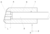
前記素線3はセラミックガラス製の円筒状のキャピラリ4に挿入され、図示しない接着剤によって接合固定される。更に、キャピラリ4と被覆2とはステンレス材などからなる円筒状のフェルール5に挿入固定される。そして、被覆2の外周面とフェルール内周面との間も前記と同様な接着剤にて接合固定される。
The
しかしながら、光ファイバ1の材料と支持部品(キャピラリ4又はフェルール5)の材料との相違による熱膨張率の不一致や、前記接着剤の硬化収縮等に起因して接合応力や熱応力(以下、総称して単に、応力という)が発生・残留すると、光ファイバ1に予め付与されている内部応力の方向が乱されてコア1a内部の複屈折性が変化し、複屈折主軸の見かけ上の回転および偏波クロストークの増加という偏波特性の劣化が引き起こされる。このような応力が光ファイバ1に加わった場合、被覆2で覆われた光ファイバ素線は、被覆2が一種の応力緩衝材として機能するため、前記応力から影響を受けることは殆ど無く、影響が現れたとしてもほぼ無視出来るほどに小さい程度のものである。
However, bonding stress and thermal stress (hereinafter referred to as generic names) due to mismatch in thermal expansion coefficient due to the difference between the material of the
しかし、素線3では被覆2が取り除かれているため、応力は緩衝されることなく光ファイバ長L(光軸上における長さとする)に亘って素線3に伝わる。よって、前記のような偏波特性の劣化が生じて光ファイバ1の消光比の大幅な劣化が発生する。
However, since the
更に、光の波長変化に伴う消光比の変化特性(波長依存性)、光ファイバ1の温度変化に伴う消光比の変化特性(温度依存性)、及び光ファイバ1の光軸方向(矢印Z方向)における長さ変化に伴う消光比の変化特性(光ファイバ長依存性)も激しくなるため、安定した消光比の特性を得ることも困難であった。図10は、図9の光ファイバ1の消光比−波長依存性特性を実測した結果の一例である。
Further, the extinction ratio change characteristic (wavelength dependence) accompanying the change in light wavelength, the extinction ratio change characteristic (temperature dependence) accompanying the temperature change of the
図10のグラフは次のようにして測定した。まず試料として全長Lf:1020mmの偏波面保存光ファイバ素線を用意し、その光ファイバをフェルール(支持部品)に挿入して光ファイバ外周面をエポキシ樹脂剤で接着し、波長可変レーザ光源で光ファイバへの入射光の波長帯域を変化させながら光ファイバの消光比を測定した。図10に示すように、消光比が前記波長の変化に対して周期的に大きく落ち込むように変動していることが分かる。 The graph of FIG. 10 was measured as follows. First, a polarization-maintaining optical fiber with a total length of Lf: 1020 mm is prepared as a sample, the optical fiber is inserted into a ferrule (supporting part), the outer peripheral surface of the optical fiber is bonded with an epoxy resin agent, and light is emitted with a tunable laser light source. The extinction ratio of the optical fiber was measured while changing the wavelength band of the incident light to the fiber. As shown in FIG. 10, it can be seen that the extinction ratio fluctuates so as to decrease significantly periodically with respect to the change in the wavelength.
ここで消光比の変動の波長周期をλbとすると、消光比落ち込みの波長周期λbは、

と導かれる。ここで、λ:波長、B:モード複屈折率、Lf:全長であり、λ:1550nm、B:0.0005、Lf:1020mmを代入すると、λb = 4.7nmと導出される。これは図10のグラフとよく一致している。
Here, if the wavelength period of fluctuation of the extinction ratio is λb, the wavelength period λb of the extinction ratio drop is
It is guided. Here, λ: wavelength, B: mode birefringence, Lf: full length, and λ: 1550 nm, B: 0.0005, Lf: 1020 mm are substituted, and λb = 4.7 nm is derived. This is in good agreement with the graph of FIG.
本発明は上記課題に鑑みてなされたものであり、その目的は、消光比の劣化及び前記劣化の波長依存性・温度依存性・光ファイバ長依存性を抑制・改善して、消光比の特性向上を可能とする偏波面保存光ファイバの固定方法を提供することである。 The present invention has been made in view of the above problems, and its purpose is to suppress extinction ratio, and to suppress / improve the wavelength dependence, temperature dependence, and optical fiber length dependence of the degradation, and to reduce extinction ratio characteristics. It is an object of the present invention to provide a method for fixing a polarization-maintaining optical fiber that can be improved.
本発明の請求項1記載の発明は、偏波面保存光ファイバを支持部品に接合固定し、その接合固定により応力が加わる前記偏波面保存光ファイバの光軸方向における光ファイバ長をL、前記偏波面保存光ファイバのビート長をLb、任意の整数をNで表すとき、前記Lを、
に設定することを特徴とする偏波面保存光ファイバの固定方法である。
According to the first aspect of the present invention, the polarization-maintaining optical fiber is bonded and fixed to a support component, and the length of the optical fiber in the optical axis direction of the polarization-maintaining optical fiber to which stress is applied by the bonding and fixing is L. When the beat length of the wavefront-preserving optical fiber is represented by Lb and an arbitrary integer is represented by N, the L is
The polarization plane preserving optical fiber fixing method is characterized in that it is set as follows.
更に、本発明の請求項2記載の発明は、前記任意の整数Nを偶数に設定することを特徴とする偏波面保存光ファイバの固定方法である。
Furthermore, the invention according to
本発明の偏波面保存光ファイバの固定方法に依れば、偏波面保存光ファイバにおいて応力が加わる光ファイバ長を、ビート長の1/2の整数倍に設定することにより、極めて簡単に且つ製作上の原価上昇を抑制して、偏波面保存光ファイバーの消光比特性を向上させることが可能となる。 According to the method of fixing a polarization-maintaining optical fiber of the present invention, the length of the optical fiber to which stress is applied in the polarization-maintaining optical fiber is set to an integral multiple of 1/2 of the beat length, which is extremely simple and can be manufactured. It is possible to improve the extinction ratio characteristic of the polarization-maintaining optical fiber by suppressing the above cost increase.
更に、前記応力が加わる光ファイバ長を、ビート長の1/2の偶数倍に設定することにより、より一層、偏波面保存光ファイバーの消光比特性の劣化を防止することが可能になる。 Furthermore, by setting the length of the optical fiber to which the stress is applied to an even multiple of 1/2 of the beat length, it is possible to further prevent the deterioration of the extinction ratio characteristic of the polarization-maintaining optical fiber.
以下、図1〜図7を参照しながら、本発明に係る偏波面保存光ファイバの固定方法について説明する。図1は本発明に係る偏波面保存光ファイバの固定方法により固定された支持部品一体型光ファイバの部分側断面図であり、図2は偏波面保存光ファイバ素線を光軸と垂直な面で切断したときの断面図であり、図3は偏波面保存光ファイバのコア内部を伝搬していく光の偏波状態を示す説明図である。なお、図8で示した従来の支持部品一体型光ファイバと同一箇所には同一番号を付し、重複する説明は省略若しくは簡略化して記述する。 Hereinafter, a method for fixing a polarization-maintaining optical fiber according to the present invention will be described with reference to FIGS. FIG. 1 is a partial cross-sectional side view of a support component-integrated optical fiber fixed by a polarization-maintaining optical fiber fixing method according to the present invention, and FIG. 2 is a plane perpendicular to the optical axis of the polarization-maintaining optical fiber. FIG. 3 is an explanatory view showing a polarization state of light propagating through the core of the polarization-maintaining optical fiber. In addition, the same number is attached | subjected to the same location as the conventional support component integrated optical fiber shown in FIG. 8, and the overlapping description is abbreviate | omitted or simplified and described.
図1、2及び図3(a)より、Y軸(2つの応力付加部1bが直線状に並ぶ軸)に対して偏波方向が+θ度ずれた直線偏光が偏波面保存光ファイバに入射されると、入射された光は、X軸・Y軸の各偏光成分における位相差の増加に対応して、図3(a):+θ度の直線偏光 → 図3(b):右(又は左)回転の楕円偏光 → 図3(c):−θ度の直線偏光 → 図3(d):左(又は右)回転の楕円偏光 → 同図(a):+θ度の直線偏光 → ・・・のように偏波状態を周期的に変化させながら、光ファイバ1のコア1a内部を伝搬して行く。なお、図3(b)と図3(d)の楕円偏光の回転方向はX軸・Y軸の各偏光成分の伝搬定数の大小関係に依存する。
1, 2 and 3 (a), linearly polarized light whose polarization direction is deviated by + θ degrees with respect to the Y-axis (the axis in which the two
図3(a)〜次の同図(a)までの1周期変化に要する偏波面保存光ファイバ1の光軸方向(矢印Z方向)における光ファイバ長をビート長Lb又は結合長と云い、ビート長Lbは次式によって表される。
ここで、λ:波長、B:モード複屈折率、Lb:ビート長をそれぞれ表し、λ:1550nm、B:0.0005を代入することにより、Lb=3.1mmが得られる。
The optical fiber length in the optical axis direction (arrow Z direction) of the polarization-maintaining
Here, λ: wavelength, B: mode birefringence, Lb: beat length, respectively, and by substituting λ: 1550 nm and B: 0.0005, Lb = 3.1 mm is obtained.
上記図3に示す(a)、(b)、(c)、(d)における各偏波状態はビート長Lbの1/4毎の位相差に対応する。θ=0度即ちY軸に一致した偏波状態の直線偏光が光ファイバ1に入射されるとき、入射光は直線偏光の状態を保持されたままコア1a内を伝搬される。
Each polarization state in (a), (b), (c), and (d) shown in FIG. 3 corresponds to a phase difference for each quarter of the beat length Lb. When linearly polarized light having a polarization state coincident with θ = 0 degrees, that is, the Y axis is incident on the
ここで、図1に示すように偏波面保存光ファイバ1の素線3を接着剤6で接合固定している接合箇所に、光ファイバ長L(光軸上における長さとする)に亘って前記接合固定に起因する応力が発生・残留する。すると、その応力によって偏波面保存光ファイバ1のコア1a内部に予め付与されている内部応力の方向(Y軸方向)と大きさに変化が生ずる。
Here, as shown in FIG. 1, the optical fiber length L (which is the length on the optical axis) is applied to the joint where the
一般的な偏波面保存光ファイバ1と支持部品(キャピラリ4又はフェルール5)との固定方法においては、接合固定による消光比への影響は、前記内部応力の方向変化が前記影響を引き起こす原因の大部分を占め、内部応力自体の大きさ(スカラー量)の変化は無視できる程度である。
In a general method of fixing the polarization-maintaining
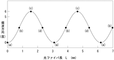
ここで、Y軸から+φ度(−45度≦φ≦+45度:ここでは一例として+3度とする)だけずれた方向の応力が、支持部品の1つであるキャピラリ4と素線3との接合箇所に加わる時、接着剤6による接合箇所の光ファイバ長Lをビート長Lbの1/2の偶数倍(即ちビート長Lbの整数倍。但し負数と零は除く。)に設定し、更にY軸方向に対する偏波ずれ角度が0度の直線偏光を偏波面保存光ファイバに入射させて、コア1a内における伝搬光の偏波状態を計測した。図4に前記接合箇所におけるコア1a内部の光の偏波状態を示すと共に、図5にコア1a内部を伝搬する光の偏波方向と光ファイバ長Lとのグラフを示す。
Here, the stress in the direction shifted by + φ degrees (−45 degrees ≦ φ ≦ + 45 degrees: +3 degrees as an example here) from the Y-axis is caused by the
すると入射光はコア1a内を、図4(a) → 図4(b) → 図4(c) → 図4(d) → 図4(a) → ・・・で表すような直線偏光と楕円偏光との周期的な偏波状態変化を繰り返しながら伝搬し(但し、偏波ずれ角度0度の直線偏光を入射させているため、(a)の偏波状態はY軸方向に対する偏波ずれ角度が0度の直線偏光であり、(c)の偏波状態はY軸に対する偏波ずれ角度が+2φ度の直線偏光である)、ビート長Lbの1/2の偶数倍毎に入射偏波方位(0度=(a)の状態)に戻ることが計測された。従って、光ファイバ長Lをビート長Lbの1/2の偶数倍に設定することにより、前記接合箇所の終端において、偏波方向がY軸方向の直線偏光が計測される。よって、被覆2で覆われた素線では、光はコア1a内部を直線偏波状態を保持したまま伝搬して行く。
Then, the incident light passes through the
次に図6に、前記光ファイバ長Lを、ビート長Lbの1/2の奇数倍に設定した場合のコア1a内部を伝搬する光の偏波方向と光ファイバ長Lとのグラフを示す。すると入射光はコア1a内を、図4(c) → 図4(d) → 図4(a) → 図4(b) → 図4(c) → ・・・で表すような直線偏光と楕円偏光との周期的な偏波状態変化を繰り返しながら伝搬し(但し、偏波ずれ角度+2φ度の直線偏光を入射させているため、(a)の偏波状態はY軸方向に対する偏波ずれ角度が0度の直線偏光であり、(c)の偏波状態はY軸に対する偏波ずれ角度が+2φ度の直線偏光である)、ビート長Lbの1/2の奇数倍毎に偏波ずれ角度=0度の偏波状態に戻ることが計測された。従って、光ファイバ長Lをビート長Lbの1/2の奇数倍に設定することにより、前記接合箇所の終端において、偏波方向がY軸方向の直線偏光が計測される。よって、被覆2で覆われた素線では、光はコア1a内部を直線偏波状態を保持したまま伝搬して行く。
Next, FIG. 6 shows a graph of the polarization direction of light propagating through the
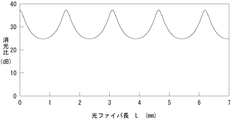
上記どちらの場合も非接合箇所(被覆2で覆われた素線箇所)でY軸方向の直線偏光となる。なお、非接合箇所で直線偏波状態を保持するためには、前記のように偶数倍時と奇数倍時とで入射光の偏波角度を異ならせる必要があるが、入射光の偏波角度については、出射光の消光比が最大になるように調整すれば良く、接合固定による応力方向の変化について特に考慮する必要は無い。しかしながら、出射光の消光比が最大になる軸方向は、応力付与方向であるY軸と、その直交方向であるX軸との2つが有る。前記偶数倍時の場合は入射光の偏波方向をY軸に一致させるため、どちらの軸に一致しているか判別し易い。一方、奇数倍時の場合はφの角度値が大きくなりY軸からのずれが大きくなると、出射光の消光比を最大に調整したとき入射光の偏波方向がどちらの軸を基準にして調整されたのか判別しにくくなる。よって、応力の方向(角度φの値)が変化する可能性を考慮して、前記光ファイバ長Lをビート長Lbの1/2の偶数倍に設定する方が、消光比の劣化抑制の点で好ましい。又、奇数倍の場合は、入射光のずれ角度が2φ度と角度設定を行った上で入射偏光を入射しなければならないため、消光比の劣化が偶数倍時に比べ若干大きくなると予測される。図7に消光比と光ファイバ長Lとのグラフを示す。図5及び図6と対照させると明らかなように、消光比はビート長Lbの1/2の整数倍周期で最大となることが判明した。 In either case, linearly polarized light in the Y-axis direction is obtained at the non-joined portion (the strand portion covered with the coating 2). In order to maintain the linearly polarized state at the non-junction portion, it is necessary to change the polarization angle of the incident light between the even times and the odd times as described above. With respect to, it is sufficient to adjust the extinction ratio of the emitted light to be maximum, and there is no need to consider in particular the change in the stress direction due to bonding and fixing. However, there are two axial directions in which the extinction ratio of the emitted light is maximized, that is, the Y axis that is the stress application direction and the X axis that is the orthogonal direction. In the case of the even multiple, since the polarization direction of the incident light coincides with the Y axis, it is easy to determine which axis coincides. On the other hand, in the case of odd multiples, if the angle value of φ increases and the deviation from the Y-axis increases, the polarization direction of the incident light is adjusted based on which axis when the extinction ratio of the emitted light is adjusted to the maximum. It becomes difficult to determine whether it was done. Therefore, considering the possibility of changing the direction of stress (value of angle φ), setting the optical fiber length L to an even multiple of 1/2 of the beat length Lb is more effective in suppressing deterioration of the extinction ratio. Is preferable. Further, in the case of an odd number, since the incident polarized light must be incident after setting the angle of deviation of incident light to 2φ degrees, it is predicted that the deterioration of the extinction ratio is slightly larger than that at the even number. FIG. 7 shows a graph of the extinction ratio and the optical fiber length L. As is clear from the comparison with FIGS. 5 and 6, it has been found that the extinction ratio becomes maximum at an integral multiple of 1/2 the beat length Lb.
なお図7より、光ファイバ長Lがビート長Lbの1/8分だけ変動したときのLbの1/8消光比の変動幅は、消光比の最大値に比べると十分小さいため、±(Lb/8)を前記光ファイバ長Lの公差分と設定できる。 From FIG. 7, since the fluctuation range of the 1/8 extinction ratio of Lb when the optical fiber length L fluctuates by 1/8 of the beat length Lb is sufficiently smaller than the maximum extinction ratio, ± (Lb / 8) can be set as the tolerance of the optical fiber length L.
X軸・Y軸の各偏光成分間の位相差δは光ファイバ長Lの依存し、
で与えられる。数4よりビート長Lbは波長λの関数であり、前記接合箇所で生じる位相差δは波長λに依存するが、前記光ファイバ長Lは光ファイバの全長Laに比べると非常に短く、またビート長Lbの数倍以内なので、接合箇所での位相差δの波長依存性は無視できる。
The phase difference δ between the polarization components of the X axis and the Y axis depends on the optical fiber length L,
Given in. From equation (4), the beat length Lb is a function of the wavelength λ, and the phase difference δ generated at the junction depends on the wavelength λ, but the optical fiber length L is very short compared to the total length La of the optical fiber, and the beat Since it is within several times the length Lb, the wavelength dependence of the phase difference δ at the junction can be ignored.
図8は、全長La:1018mmの偏波面保存光ファイバ(B:0.0005)の素線を、接合箇所の長さ:3.1mm(Lb/2の2倍)のフェルールに挿入・樹脂接着剤により接合固定したときの、偏波面保存光ファイバの消光比の波長依存性を実測した結果である。前記図10と比較すると、波長変化による消光比の落ち込みの変動が大きく減少していることが分かる。 Fig. 8 shows a method of inserting a strand of polarization-maintaining optical fiber (B: 0.0005) with a total length La: 1018 mm into a ferrule with a length of 3.1 mm (twice Lb / 2) and joining with a resin adhesive. It is the result of having actually measured the wavelength dependence of the extinction ratio of the polarization-maintaining optical fiber when fixed. Compared with FIG. 10, it can be seen that the fluctuation of the extinction ratio drop due to the wavelength change is greatly reduced.
消光比の波長依存性はX軸・Y軸の各偏光成分間の位相差に起因するので、同じ位相差に起因する温度依存性・光ファイバ長依存性も大きく改善できることは明らかである。 Since the wavelength dependence of the extinction ratio is caused by the phase difference between the polarization components of the X axis and the Y axis, it is clear that the temperature dependence and optical fiber length dependence caused by the same phase difference can be greatly improved.
本発明の偏波面保存光ファイバの固定方法を、光通信や光計測、光センサ等で使用されている偏波面保存光ファイバに適用することにより、偏波を利用した光学装置の消光比特性を向上させることができる。 By applying the polarization-maintaining optical fiber fixing method of the present invention to a polarization-maintaining optical fiber used in optical communication, optical measurement, optical sensors, etc., the extinction ratio characteristic of an optical device using polarization can be improved. Can be improved.
1 偏波面保存光ファイバ
1a コア
1b 応力付与部
1c クラッド
2 被覆
3 素線
4 キャピラリ
5 フェルール
6 接着剤
1 Polarization plane preserving optical fiber
1a core
1b Stress application part
Claims (2)
に設定することを特徴とする偏波面保存光ファイバの固定方法。 The polarization-maintaining optical fiber is bonded and fixed to a support component, and the optical fiber length in the optical axis direction of the polarization-maintaining optical fiber to which stress is applied by the bonding and fixing is L, and the beat length of the polarization-maintaining optical fiber is Lb When the integer of is represented by N, the L is
A method for fixing a polarization-maintaining optical fiber, characterized in that:
Priority Applications (1)
| Application Number | Priority Date | Filing Date | Title |
|---|---|---|---|
| JP2003336203A JP2005106865A (en) | 2003-09-26 | 2003-09-26 | Method for fixing plane-of-polarization conservative optical fiber |
Applications Claiming Priority (1)
| Application Number | Priority Date | Filing Date | Title |
|---|---|---|---|
| JP2003336203A JP2005106865A (en) | 2003-09-26 | 2003-09-26 | Method for fixing plane-of-polarization conservative optical fiber |
Publications (1)
| Publication Number | Publication Date |
|---|---|
| JP2005106865A true JP2005106865A (en) | 2005-04-21 |
Family
ID=34532413
Family Applications (1)
| Application Number | Title | Priority Date | Filing Date |
|---|---|---|---|
| JP2003336203A Pending JP2005106865A (en) | 2003-09-26 | 2003-09-26 | Method for fixing plane-of-polarization conservative optical fiber |
Country Status (1)
| Country | Link |
|---|---|
| JP (1) | JP2005106865A (en) |
Cited By (3)
| Publication number | Priority date | Publication date | Assignee | Title |
|---|---|---|---|---|
| JP2008070349A (en) * | 2006-08-15 | 2008-03-27 | Fujifilm Corp | Optical tomographic imaging apparatus |
| JP2008070350A (en) * | 2006-08-15 | 2008-03-27 | Fujifilm Corp | Optical tomographic imaging apparatus |
| CN115585985A (en) * | 2022-10-19 | 2023-01-10 | 深圳市新联恒光电科技有限公司 | Performance index monitoring system suitable for polarization maintaining optical fiber device |
-
2003
- 2003-09-26 JP JP2003336203A patent/JP2005106865A/en active Pending
Cited By (4)
| Publication number | Priority date | Publication date | Assignee | Title |
|---|---|---|---|---|
| JP2008070349A (en) * | 2006-08-15 | 2008-03-27 | Fujifilm Corp | Optical tomographic imaging apparatus |
| JP2008070350A (en) * | 2006-08-15 | 2008-03-27 | Fujifilm Corp | Optical tomographic imaging apparatus |
| CN115585985A (en) * | 2022-10-19 | 2023-01-10 | 深圳市新联恒光电科技有限公司 | Performance index monitoring system suitable for polarization maintaining optical fiber device |
| CN115585985B (en) * | 2022-10-19 | 2023-08-18 | 深圳市新联恒光电科技有限公司 | Performance index monitoring system suitable for polarization maintaining fiber device |
Similar Documents
| Publication | Publication Date | Title |
|---|---|---|
| US5692082A (en) | Laser diode module and depolarizer | |
| US7289687B2 (en) | Polarization-maintaining optical fiber | |
| JP2000515653A (en) | Optical fiber polarization controller | |
| US6377727B1 (en) | Passive temperature-compensating package for fiber Bragg grating devices | |
| CA2309564C (en) | Method of manufacturing polarization-maintaining optical fiber coupler | |
| EP0520282A2 (en) | Fiber optic gyro | |
| KR980010470A (en) | Optical fiber coupler and its manufacturing method | |
| CA2357991C (en) | Optical phase shifting, splitting and combining device | |
| JP2005106865A (en) | Method for fixing plane-of-polarization conservative optical fiber | |
| WO2004095095A1 (en) | Athermal package for fiber bragg gratings with compensation for non-linear thermal response | |
| US6535654B1 (en) | Method for fabrication of an all fiber polarization retardation device | |
| EP3410066B1 (en) | Hollow core fiber pigtail system and method | |
| JP4854251B2 (en) | Optical isolator | |
| JP6017169B2 (en) | Photocurrent detection device and method of manufacturing photocurrent detection device | |
| US7653269B1 (en) | Quasi PM fused coupler devices and methods for forming the same | |
| JP4421143B2 (en) | Polarization-maintaining optical fiber grating, optical module, and optical communication system | |
| US7065267B2 (en) | Athermal fused coupler package for optical fibers | |
| JPH05288963A (en) | Waveguide device | |
| JPS6155623A (en) | Optical isolator and light source provided with isolator | |
| CN110646895A (en) | Optical receptacle and optical transceiver | |
| JPH10221014A (en) | Optical wave guide path displacement sensor | |
| JPS5981618A (en) | Optical coupler | |
| JPS60113214A (en) | Fiber type optical switch | |
| JPH09105832A (en) | Optical fiber type coupler | |
| JPH0238923A (en) | Method for restraining noises of optical fiber sensor |
Legal Events
| Date | Code | Title | Description |
|---|---|---|---|
| A621 | Written request for application examination |
Free format text: JAPANESE INTERMEDIATE CODE: A621 Effective date: 20060925 |
|
| A521 | Written amendment |
Effective date: 20070910 Free format text: JAPANESE INTERMEDIATE CODE: A523 |
|
| A977 | Report on retrieval |
Free format text: JAPANESE INTERMEDIATE CODE: A971007 Effective date: 20080821 |
|
| A131 | Notification of reasons for refusal |
Free format text: JAPANESE INTERMEDIATE CODE: A131 Effective date: 20080829 |
|
| A521 | Written amendment |
Free format text: JAPANESE INTERMEDIATE CODE: A523 Effective date: 20081024 |
|
| A02 | Decision of refusal |
Free format text: JAPANESE INTERMEDIATE CODE: A02 Effective date: 20090402 |