JP2005106295A - Air conditioner wiring connection structure - Google Patents
Air conditioner wiring connection structure Download PDFInfo
- Publication number
- JP2005106295A JP2005106295A JP2003286521A JP2003286521A JP2005106295A JP 2005106295 A JP2005106295 A JP 2005106295A JP 2003286521 A JP2003286521 A JP 2003286521A JP 2003286521 A JP2003286521 A JP 2003286521A JP 2005106295 A JP2005106295 A JP 2005106295A
- Authority
- JP
- Japan
- Prior art keywords
- power supply
- wiring
- indoor
- outdoor unit
- connection
- Prior art date
- Legal status (The legal status is an assumption and is not a legal conclusion. Google has not performed a legal analysis and makes no representation as to the accuracy of the status listed.)
- Pending
Links
Images

Landscapes
- Air Filters, Heat-Exchange Apparatuses, And Housings Of Air-Conditioning Units (AREA)
Abstract
【課題】 室外ユニットからの電源の繋ぎ線の有無に関わらず室内ユニットを交換してもユニット間の繋ぎ既設配線を活用できるようにした空気調和機の配線接続構造を提供する。
【解決手段】室外ユニットと室内ユニットからなり、互いのユニットが繋ぎ配線を介して接続される空気調和機の配線接続構造において、電源中継接続部が、室外ユニットの電源又は室外ユニット以外の外部電源のいずれか一方と選択接続できるように室内ユニットの電源回路内に設けられ、室外ユニットからの繋ぎ配線の電源繋ぎ線の有無に関わらず室内ユニットを交換しても繋ぎ配線の既設配線を活用できるようにしたものである。
【選択図】図1PROBLEM TO BE SOLVED: To provide a wiring connection structure for an air conditioner that can connect existing units and utilize existing wirings even if the indoor units are replaced regardless of the presence or absence of a power source connecting line from an outdoor unit.
In a wiring connection structure of an air conditioner that includes an outdoor unit and an indoor unit, and each unit is connected and connected via a wiring, the power relay connection portion is a power supply for the outdoor unit or an external power supply other than the outdoor unit. It is provided in the power circuit of the indoor unit so that it can be selectively connected to either of them, and the existing wiring of the connecting wiring can be utilized even if the indoor unit is replaced regardless of the presence or absence of the power connecting wire of the connecting wiring from the outdoor unit It is what I did.
[Selection] Figure 1
Description
この発明は、既設工事配線を活用して室内ユニットと室外ユニットとを配線接続する空気調和機の配線接続構造に関するものである。 The present invention relates to a wiring connection structure of an air conditioner that uses existing construction wiring to connect an indoor unit and an outdoor unit.
従来の室内ユニットの配線接続構造においては、既設の室外ユニットと室内ユニットのいずれか一方が寿命等で故障し、新しいスペックの室外ユニットや室内ユニットに置き変える時、互いの新旧ユニットのスペックが同じ時は、問題は生じないものの、一般的に、寿命期間を挟んだ新旧ユニットのスペックは技術の進歩の関係から必然的に異なり、その結果、交換ユニット間のスペックが相違して、ユニット間の繋ぎ配線の本数や太さが相違するため、室内外ユニット間を接続する通信配線や電源配線等の既設の繋ぎ配線も新規に変えなければならなかった。
(特許文献1参照)
In the conventional indoor unit wiring connection structure, when either the existing outdoor unit or the indoor unit fails due to its lifetime, etc., and it is replaced with a new specification outdoor unit or indoor unit, the specifications of the old and new units are the same. At times, there will be no problem, but in general, the specifications of the old and new units with different life spans will inevitably differ due to technological progress. Since the number and thickness of connecting wires are different, existing connecting wires such as communication wires and power supply wires for connecting between indoor and outdoor units have to be newly changed.
(See Patent Document 1)
即ち、例えば、図6の如く、既設の室外ユニット10と既設の室内ユニット22が通信配線のみの2本で結ばれ、室内ユニット22の電源配線が室外ユニット以外の外部電源に2本の線で接続された配線構造において、この既設の室外ユニット10又は室内ユニット22の一方が寿命故障し、図5のような通信配線と電源配線とを3本線で構成した繋ぎ配線の工事性の良い室外ユニット1又は室内ユニット20に交換する時、室内外ユニット間を接続する繋ぎ配線本数やその太さが相違するため、既設の繋ぎ配線も新規なものに変えなければならなかった。 That is, for example, as shown in FIG. 6, the existing outdoor unit 10 and the existing indoor unit 22 are connected by only two communication wires, and the power supply wiring of the indoor unit 22 is connected to an external power source other than the outdoor unit by two wires. In the connected wiring structure, one of the existing outdoor unit 10 or the indoor unit 22 has a life failure, and the outdoor unit with good workability of the connecting wiring in which the communication wiring and the power supply wiring as shown in FIG. When replacing with 1 or the indoor unit 20, the number of connecting wires connecting the indoor and outdoor units and the thickness thereof are different, so the existing connecting wires have to be changed to new ones.
また逆に、通信配線と電源配線とを3本線の繋ぎ配線で構成した既設の室外ユニット1と室内ユニット20が寿命故障し、通信配線のみの細い2本の配線で結ばれた室外ユニット10又は室内ユニット22に交換する時も、同様に、室内外ユニット間を接続する繋ぎ配線本数やその太さが相違するため、新規な繋ぎ配線に変えなければならなかった。
On the contrary, the existing
即ち、一般的に、室内外ユニット間を通信配線と電源配線からなる3本線の繋ぎ配線で接続する時は、電源ノイズが通信配線に入らないようにするため、丸形3芯線を用いず、平形3芯線を用い、また、室内外ユニット間が2芯の通信配線のみので接続されている時は、通電電圧が低いため、電源配線よりも細い配線を用いてコストを下げるのが一般的なやり方であるから、益々、新規な繋ぎ配線に変えなければならないこととなる。 That is, generally, when connecting between indoor and outdoor units with a three-wire connecting line consisting of communication wiring and power supply wiring, in order to prevent power noise from entering the communication wiring, a round three-core wire is not used. When a flat three-core wire is used and the indoor / outdoor units are connected with only two-core communication wiring, the energizing voltage is low, so it is common to reduce the cost by using a wiring thinner than the power supply wiring. Since it is a method, it will be increasingly necessary to change to new connection wiring.
以上説明したように、従来の空気調和機の配線接続構造においては、既設の室内外ユニットが寿命故障し、新しいスペックの室内外ユニットに変える時は、既設の室内外ユニット間を接続している既設の繋ぎ配線本数が変わったり、その既設の繋ぎ配線の太さも電源線と通信線では変るため、既設の繋ぎ配線も変えなけばならいこととなり、工期や工費がかかるなどの問題点があった。 As described above, in the conventional air conditioner wiring connection structure, when an existing indoor / outdoor unit fails in life and is changed to a new spec indoor / outdoor unit, the existing indoor / outdoor unit is connected. Since the number of existing connecting wires changes, and the thickness of the existing connecting wires also changes between the power supply line and the communication line, it is necessary to change the existing connecting wires, which causes problems such as construction period and cost. .
この発明は、上記のような問題点を解決するためになされたもので、室内外ユニットを交換する時、室内外ユニット間の既設繋ぎ配線の本数や太さ形状が変化しても、室内外ユニット間を接続できる経済的な空気調和機の配線接続構造を提供することを目的とする。 The present invention has been made to solve the above-described problems. When the indoor / outdoor units are replaced, even if the number and thickness of existing connecting wires between the indoor / outdoor units change, the indoor / outdoor An object of the present invention is to provide an economical air conditioner wiring connection structure capable of connecting units.
この発明に係る空気調和機の配線接続構造においては、室外ユニットと室内ユニットからなり、互いのユニットが繋ぎ配線を介して接続される空気調和機の配線接続構造において、電源中継接続部が、前記室外ユニットの電源又は前記室外ユニット以外の外部電源のいずれか一方と選択接続できるように前記室内ユニットの電源回路内に設けられ、前記室外ユニットからの前記繋ぎ配線の電源繋ぎ線の有無に関わらず前記室内ユニットを交換しても前記繋ぎ配線の既設配線を活用できるようにしたものである。 In the air conditioner wiring connection structure according to the present invention, the air conditioner wiring connection structure includes an outdoor unit and an indoor unit, and each unit is connected and connected via a wiring. Provided in the power supply circuit of the indoor unit so that it can be selectively connected to either the power supply of the outdoor unit or the external power supply other than the outdoor unit, regardless of the presence or absence of the power supply line of the connecting wiring from the outdoor unit Even if the indoor unit is replaced, the existing wiring of the connecting wiring can be utilized.
また、前記電源中継接続部が、前記室外ユニットの電源回路に前記繋ぎ配線を介して接続された室外機用電源接続部と、前記室外ユニット以外の外部電源回路に前記繋ぎ配線を介して接続された外部用電源接続部と、この外部用電源接続部又は前記室外機用電源接続部のいずれか一方と脱着自在に接続され、前記室内ユニットの電源回路に配線で連絡された室内電源接続部と、を具備したものである。 In addition, the power supply relay connection portion is connected to the power supply circuit for the outdoor unit connected to the power supply circuit of the outdoor unit via the connection wiring, and is connected to the external power supply circuit other than the outdoor unit via the connection wiring. An external power supply connection portion, and an indoor power supply connection portion that is detachably connected to either the external power supply connection portion or the outdoor unit power supply connection portion and is connected to the power supply circuit of the indoor unit by wiring. , Are provided.
また、前記電源中継接続部が、前記室外ユニットの電源回路に前記繋ぎ配線を介して接続された室外機用接続接続部と、前記室外ユニット以外の外部電源回路に前記繋ぎ配線を介して接続された外部用電源接続部と、この外部用電源接続部又は前記室外機用電源接続部のいずれか一方を脱着自在に装着して前記室内ユニットの電源回路に配線で連絡された室内電源接続部と、前記外部用電源接続部又は前記室外機用電源接続部のいずれか一方のその他方を脱着自在に装着するダミー接続部と、を具備したものである。 In addition, the power relay connection portion is connected to an outdoor unit connection connection portion connected to the power circuit of the outdoor unit via the connection wiring, and connected to an external power supply circuit other than the outdoor unit via the connection wiring. An external power supply connection portion, and an indoor power supply connection portion that is detachably attached to either the external power supply connection portion or the outdoor unit power supply connection portion and is connected to the power supply circuit of the indoor unit by wiring. And a dummy connection part for detachably attaching the other one of the external power supply connection part and the outdoor unit power supply connection part.
また、前記室内電源接続部がピン状の差込み構造からなり、前記外部用電源接続部又は前記室外機用電源接続部とワンタッチで差換え接続できるように構成されたものである。 In addition, the indoor power supply connection portion has a pin-like insertion structure, and is configured to be exchanged and connected to the external power supply connection portion or the outdoor unit power supply connection portion with one touch.
また、前記外部用電源接続部と前記室外機用電源接続部がそれぞれ識別できるように互いに異なった色又は識別符号を有するものである。 Further, the external power supply connection part and the outdoor unit power supply connection part have different colors or identification codes so that they can be distinguished from each other.
また、前記室内電源接続部の電圧を検出する電圧検出手段と、この電圧検出手段の検出結果に基づいて前記室内電源接続部への電圧供給有無を知らせる告知手段と、を具備したものである。 In addition, a voltage detection unit that detects a voltage of the indoor power supply connection unit and a notification unit that notifies the presence or absence of voltage supply to the indoor power supply connection unit based on a detection result of the voltage detection unit.
以上説明したように、この発明においては、室外ユニットと室内ユニットからなり、互いのユニットが繋ぎ配線を介して接続される空気調和機の配線接続構造において、電源中継接続部が、前記室外ユニットの電源又は前記室外ユニット以外の外部電源のいずれか一方と選択接続できるように前記室内ユニットの電源回路内に設けられ、前記室外ユニットからの前記繋ぎ配線の電源繋ぎ線の有無に関わらず前記室内ユニットを交換しても前記繋ぎ配線の既設配線を活用できるようにしたので、室内外ユニットを交換する時、室内外ユニット間の既設繋ぎ配線の本数や太さ形状が変化しても、既設繋ぎ配線を利用して室内外ユニット間を接続できる経済的な空気調和機の配線接続構造が得られる。 As described above, in the present invention, in the wiring connection structure of an air conditioner that includes an outdoor unit and an indoor unit, and each unit is connected and connected via a wiring, the power supply relay connection portion includes the outdoor unit. The indoor unit is provided in the power circuit of the indoor unit so that it can be selectively connected to either a power source or an external power source other than the outdoor unit, regardless of the presence or absence of the power source connecting line of the connecting wiring from the outdoor unit. Since the existing wiring of the connecting wiring can be utilized even if the indoor / outdoor unit is replaced, the existing connecting wiring can be replaced even if the number and thickness of the existing connecting wiring between the indoor and outdoor units change. An economical air conditioner wiring connection structure that can connect between indoor and outdoor units is obtained.
また、前記電源中継接続部が、前記室外ユニットの電源回路に前記繋ぎ配線を介して接続された室外機用電源接続部と、前記室外ユニット以外の外部電源回路に前記繋ぎ配線を介して接続された外部用電源接続部と、この外部用電源接続部又は前記室外機用電源接続部のいずれか一方と脱着自在に接続され、前記室内ユニットの電源回路に配線で連絡された室内電源接続部と、を具備したので、室外ユニットからの電源繋ぎ線の有無に関わらず繋ぎ配線3の既設配線を活用して新しい室内ユニット2に交換できるようにしたので、空気調和機をリプレースする場合に、繋ぎ配線を新しく配設する必要がなくなるため、工期や工費を大幅に縮減した空気調和機の配線接続構造が得られる。
In addition, the power supply relay connection portion is connected to the power supply circuit for the outdoor unit connected to the power supply circuit of the outdoor unit via the connection wiring, and is connected to the external power supply circuit other than the outdoor unit via the connection wiring. An external power supply connection portion, and an indoor power supply connection portion that is detachably connected to either the external power supply connection portion or the outdoor unit power supply connection portion and is connected to the power supply circuit of the indoor unit by wiring. Therefore, the existing wiring of the connecting wiring 3 can be replaced with a new
また、前記電源中継接続部が、前記室外ユニットの電源回路に前記繋ぎ配線を介して接続された室外機用電源接続部と、前記室外ユニット以外の外部電源回路に前記繋ぎ配線を介して接続された外部用電源接続部と、この外部用電源接続部又は前記室外機用電源接続部のいずれか一方を脱着自在に装着して前記室内ユニットの電源回路に配線で連絡された室内電源接続部と、前記外部用電源接続部又は前記室外機用電源接続部のいずれか一方のその他方を脱着自在に装着するダミー接続部と、を具備したので、室外ユニットからの電源繋ぎ線の有無に関わらず繋ぎ配線3の既設配線を活用して新しい室内ユニット2に交換できるようになるため、空気調和機をリプレースする場合に、繋ぎ配線を新しく配設する必要がなくなるため、工期や工費を大幅に縮減した空気調和機の配線接続構造が得られる。
In addition, the power supply relay connection portion is connected to the power supply circuit for the outdoor unit connected to the power supply circuit of the outdoor unit via the connection wiring, and is connected to the external power supply circuit other than the outdoor unit via the connection wiring. An external power supply connection portion, and an indoor power supply connection portion that is detachably attached to either the external power supply connection portion or the outdoor unit power supply connection portion and is connected to the power supply circuit of the indoor unit by wiring. And a dummy connection part that detachably attaches the other one of the external power supply connection part and the outdoor unit power supply connection part, regardless of the presence or absence of a power connection line from the outdoor unit. Since the existing wiring of the connecting wiring 3 can be used and replaced with a new
また、前記室内電源接続部がピン状の差込み構造からなり、前記外部用電源接続部又は前記室外機用電源接続部とワンタッチで差換え接続できるように構成されたので、配線接続の容易な空気調和機の配線接続構造が得られる。 In addition, the indoor power supply connection portion has a pin-like insertion structure, and is configured to be replaced and connected to the external power supply connection portion or the outdoor unit power supply connection portion with one touch. The wiring connection structure of the machine is obtained.
また、前記外部用電源接続部と前記室外機用電源接続部がそれぞれ識別できるように互いに異なった色又は識別符号を有するので、配線接続の容易な空気調和機の配線接続構造が得られる。 In addition, since the external power supply connection portion and the outdoor unit power supply connection portion have different colors or identification codes so that they can be distinguished from each other, a wiring connection structure of an air conditioner that can be easily connected is obtained.
また、前記室内電源接続部の電圧を検出する電圧検出手段と、この電圧検出手段の検出結果に基づいて前記室内電源接続部への電圧供給有無を知らせる告知手段と、を具備したので、配線工事誤りの有無が解る使い勝手の良い空気調和機の配線接続構造が得られる。 Further, since the voltage detection means for detecting the voltage of the indoor power supply connection portion and the notification means for notifying the presence or absence of voltage supply to the indoor power supply connection portion based on the detection result of the voltage detection means, wiring work is provided. An easy-to-use air conditioner wiring connection structure in which the presence or absence of an error can be understood.
実施の形態1.
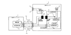
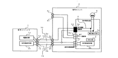
以下、この発明の実施の形態1について図1および図2を用いて説明する。なお、図1はこの発明の実施の形態1における室内外ユニット間を電源繋ぎ線と通信繋ぎ線で結んだ空気調和機の配線接続構造の概略構成図であり、図2はこの発明の実施の形態1における室内外ユニット間を通信繋ぎ線のみで結んだ空気調和機の配線接続構造の概略構成図である。
これらの図において、1は室外ユニットであり、1aは室外ユニット1の室外電源出力端子であり、1bは室外ユニット1の室外側通信出力端子であり、1cは室外ユニット1の電源回路であり、1dは室外ユニット1の室外側通信回路である。
In these drawings, 1 is an outdoor unit, 1a is an outdoor power output terminal of the
また、2は室内ユニットであり、2aは室内ユニット2の室内側電源入力端子であり、2bは室内ユニット2の室内側通信入力端子であり、2cは室内ユニット以外の外部電源が接続される室内側外部入力端子であり、2eはこの室内側外部入力端子2cに接続された電源中継接続部としての外部用電源接続部であり、2dは前述の室内側電源入力端子2aに接続された電源中継接続部としての室外機用電源接続部である。
2 is an indoor unit, 2a is an indoor power input terminal of the
また、3は室内外ユニット1,2間を繋ぐ繋ぎ配線であり、3aはこの繋ぎ配線3の室外側通信出力端子1bと室内側通信入力端子2bとを繋ぐ通信用繋ぎ配線であり、3bは室外電源出力端子1aと室内側電源入力端子2aとを繋ぐ電源用繋ぎ配線であり、3cは図2に示す如く、室内ユニット以外の外部電源と室内側外部入力端子2cを繋ぐ外部電源用繋ぎ配線である。
なお、電源用繋ぎ配線は電圧の関係から通信用繋ぎ配線よりも太いのが一般的であり、また、図1の如く、電源用繋ぎ配線3bと通信用繋ぎ配線3aがコモン配線を共用して一体化された3本線のものは平形3芯線を用いるのが電源ノイズの関係から一般的である。
Reference numeral 3 denotes a connecting wire connecting the
The power connection wiring is generally thicker than the communication connection wiring because of the voltage, and as shown in FIG. 1, the power connection wiring 3b and the communication connection wiring 3a share a common wiring. For the integrated three wires, a flat three-core wire is generally used because of power supply noise.
また、4は室内ユニット2の室内電気回路の電源回路であり、4aはこの室内電気回路の電源回路4に設けられ、電源中継接続部の室外機用電源接続部2d又は外部用電源接続部2eのいずれか一方に選択接続されて室内ユニット2の電源回路4へ電源を供給する電源中継接続部の室内電源接続部であり、8は室内側通信入力端子2bに接続された通信回路であり、8aはその通信回路の通信回路接続部である。
Reference numeral 4 denotes a power supply circuit for the indoor electric circuit of the
また、5は室外ユニット1以外の外部電源であり、5cはこの外部電源の電源出力端子で、6は室内電気回路に接続されて制御される各種機器であり、7は室内電源接続部4aの電圧状態を告知する告知手段であり、7aはこの告知手段7へ室内電源接続部4aの電圧を検出して送信する電圧検出手段である。
Reference numeral 5 denotes an external power source other than the
次に、このように構成された室内ユニットと室外ユニットとの間の既設配線を活用して空気調和機をリプレースする動作について説明する。
まず、この発明の室内ユニット2は、前述したように、電源中継接続部は、室外ユニット1の電源回路1cに既設の電源用繋ぎ配線3bを介して接続された室外機用電源接続部2dと、室外ユニット以外の外部電源5の回路に既設の外部電源用繋ぎ配線3cを介して接続された外部用電源接続部2eと、この外部用電源接続部2e又は室外機用電源接続部2dのいずれか一方と脱着自在に選択接続でき、室内ユニット2の電源回路に配線で連絡された室内電源接続部4aとからなるので、例えば、図5のような通信配線と電源配線3本線の繋ぎ配線3で接続された既設の室内外ユニットのうち、室内ユニット20が寿命故障して、新スペックの室内ユニット2に交換する時は、図1の如く、既設配線の本数とその太さ・形状も変わらないので、そのまま室内ユニットのみを交換した後、この室内ユニットの室内側電源入力端子2a及び室内側通信入力端子2bに既設の通信及び電源の繋ぎ配線3a,3bからなる3芯の繋ぎ配線3を接続して空気調和機を運転することになる。
Next, an operation for replacing the air conditioner using the existing wiring between the indoor unit and the outdoor unit configured as described above will be described.
First, as described above, in the
何故なら、この時、図1の如く、室内電源接続部4aは室内ユニット2の室内側電源入力端子2aに接続された室外機用電源接続部2dに接続されて製品出荷されているので、電源中継接続部の接続回路を弄くる必要がない。
また、室外ユニット1が寿命故障した時は、同じ電源回路付スペックの室外ユニット1に交換した後、室外ユニット1の室外電源出力端子1a及び室外側通信出力端子1bに既設の平形3芯繋ぎ配線3を接続して空気調和機を運転することになる。
Because at this time, as shown in FIG. 1, the indoor power supply connection portion 4a is connected to the outdoor unit power supply connection portion 2d connected to the indoor side power supply input terminal 2a of the
In addition, when the
次に、図6のような室内外ユニット間の繋ぎ線が通信配線のみからなり、室内ユニット22の電源を室外ユニット以外の外部電源5から取っている既設の室内外ユニットのうち、室内ユニット22が寿命故障して、新スペックの室内ユニット2に交換する時は、図2の如く、既設配線の本数とその太さ・形状は変わらず、室内ユニット2の電源接続回路のみが変わっているので、室内ユニット2を交換した後、室外機用電源接続部2dと接続されていた室内電源接続部4aを室外機用電源接続部2dから取外し、外部用電源接続部2eに接続変更した後、室内ユニット2の室内側通信入力端子2b及び外部電源入力端子2cに既設の2芯の通信用及び電源用繋ぎ配線3a、3cをぞれぞれ接続して空気調和機を運転することになる。
Next, among the existing indoor / outdoor units in which the connecting line between the indoor and outdoor units as shown in FIG. 6 consists only of communication wiring, and the power supply of the indoor unit 22 is taken from the external power supply 5 other than the outdoor unit, the indoor unit 22 However, when replacing the
また、室外ユニット10が寿命故障した時は、同じ外部電源スペックの室外ユニット10に交換した後、室外ユニット2の室外側通信出力端子1b及び外部電源出力端子5cに既設の2芯の各繋ぎ配線3a、3cをそれぞれ接続して空気調和機を運転することになる。
なお、この時、寿命故障した室外ユニット10を室外ユニット1に交換した時は、寿命時間の関係から室内ユニット22も室内ユニット2に変えた時も、前述したように、図2の如く、既設の2芯の通信用及び外部電源用繋ぎ配線3a、3cを活用して運転するようになる。
Also, when the outdoor unit 10 fails in life, it is replaced with an outdoor unit 10 having the same external power supply specifications, and then the existing two-core connecting wires are connected to the outdoor communication output terminal 1b and the external power supply output terminal 5c of the
At this time, when the outdoor unit 10 whose life has failed is replaced with the
以上説明したように、室内ユニット2の電源中継接続部が、室外ユニット1の電源回路1cに既設の電源用繋ぎ配線3bを介して接続された室外機用電源接続部2dと、室外ユニット以外の外部電源5の回路に既設の外部電源用繋ぎ配線3cを介して接続された外部用電源接続部2eと、この外部用電源接続部2e又は室外機用電源接続部2dのいずれか一方と脱着自在に選択接続でき、室内ユニット2の電源回路に配線で連絡された室内電源接続部4aとを具備し、室外ユニットからの電源の繋ぎ配線の有無に関わらず繋ぎ配線3の既設配線を活用して新しい室内ユニット2に交換できるようにしたので、空気調和機をリプレースする場合に、繋ぎ配線を新しく配設工事する必要がなくなるため、工期や工費を大幅に縮減した空気調和機の配線接続構造が得られる。
As described above, the power supply relay connection part of the
実施の形態2.
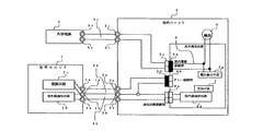
以下、この発明の実施の形態2について図3および図4を用いて説明する。なお、図3はこの発明の実施の形態2における室内外ユニット間を電源繋ぎ線と通信繋ぎ線で結んだ空気調和機の配線接続構造の概略構成図であり、図4はこの発明の実施の形態1における室内外ユニット間を通信繋ぎ線のみで結んだ空気調和機の配線接続構造の概略構成図である。
The second embodiment of the present invention will be described below with reference to FIGS. 3 is a schematic configuration diagram of a wiring connection structure of an air conditioner in which the indoor and outdoor units in the second embodiment of the present invention are connected to each other by a power connection line and a communication connection line, and FIG. 4 is a diagram of the embodiment of the present invention. It is a schematic block diagram of the wiring connection structure of the air conditioner which connected the indoor unit and the outdoor unit in
また、この実施の形態2においては、室内ユニットの電源中継接続部が、室外ユニットの電源回路に前記繋ぎ配線を介して接続される室外機用電源接続部2dと、室外ユニット以外の外部電源回路に前記繋ぎ配線を介して接続される外部用電源接続部2eと、この外部用電源接続部又は前記室外機用電源接続部のいずれか一方を脱着自在に装着して室内ユニットの電源回路に配線で連絡された室内電源接続部4eと、前記外部用電源接続部又は前記室外機用電源接続部のいずれか一方のその他方を脱着自在に装着するダミー接続部4dとからなるものであり、その他の構成は実施の形態1とほぼ同じである。 Further, in the second embodiment, the power relay connection portion of the indoor unit is connected to the power supply circuit 2d for the outdoor unit connected to the power circuit of the outdoor unit via the connecting wiring, and the external power supply circuit other than the outdoor unit The external power supply connection portion 2e connected via the connecting wiring and either the external power supply connection portion or the outdoor unit power supply connection portion are detachably attached and wired to the power supply circuit of the indoor unit And a dummy connection portion 4d for detachably mounting the other one of the external power supply connection portion and the outdoor unit power supply connection portion. The configuration is substantially the same as that of the first embodiment.
次に、このように構成された室内ユニットと室外ユニットとの間の既設配線を活用して空気調和機をリプレースする動作について説明する。
まず、この室内ユニット2は、前述したように構成されているので、例えば、図5のような通信配線と電源配線3本線の繋ぎ配線3で接続された既設の室内外ユニットのうち、室内ユニット20が寿命故障して、新スペックの室内ユニット2に交換する時は、図3の如く、既設配線の本数とその太さ・形状も変わらないので、そのまま室内ユニット2に交換した後、室内ユニット2の室内側電源入力端子2a及び室内側通信入力端子2bに既設の平形3芯の通信及び電源の繋ぎ配線3a,3bからなる繋ぎ配線3を接続して空気調和機を運転することになる。
Next, an operation for replacing the air conditioner using the existing wiring between the indoor unit and the outdoor unit configured as described above will be described.
First, since the
何故なら、この時、図3の如く、室内電源接続部4aは室内ユニット2の室外機用電源接続部2dに接続され、ダミー接続部4dは室内側外部入力端子2cに接続されて製品出荷されているので、電源中継接続部の接続回路を弄くる必要がない。
また、室外ユニット1が寿命故障した時は、同じ電源回路付スペックの室外ユニット1に交換した後、室外ユニット1の室外電源出力端子1a及び室外側通信出力端子1bに既設の3芯繋ぎ配線3を接続して空気調和機を運転することになる。
This is because at this time, as shown in FIG. 3, the indoor power supply connection portion 4a is connected to the outdoor unit power supply connection portion 2d of the
Further, when the
次に、図6のような室内外ユニット間の繋ぎ線が通信配線のみからなり、室内ユニット22の電源を室外ユニット以外の外部電源5から取っている既設の室内外ユニットのうち、室内ユニット22が寿命故障して、新スペックの室内ユニット2に交換する時は、図4の如く、既設配線の本数とその太さ・形状は変わらず、室内ユニット2の電源接続回路のみが変わているので、室内ユニット2を交換した後、室内電源接続部4aに接続されていた室外機用電源接続部2dを取外す共に、ダミー接続部4dに接続されていた外部用電源接続部2eを取外し、これらの取外した外部用電源接続部2eを室内電源接続部4aに接続すると共に、室外機用電源接続部2dをダミー接続部4dに接続した後、室内ユニット2の室内側通信入力端子2b及び外部電源入力端子2cに既設の2芯の通信用及び電源用繋ぎ配線3a、3cをそれぞれ接続して空気調和機を運転することになる。
Next, among the existing indoor / outdoor units in which the connecting line between the indoor and outdoor units as shown in FIG. 6 consists only of communication wiring, and the power supply of the indoor unit 22 is taken from the external power supply 5 other than the outdoor unit, the indoor unit 22 However, when replacing the
また、室外ユニット10が寿命故障した時は、同じ外部電源スペックの室外ユニット10に交換した後、室外ユニット10の室外側通信出力端子1b及び外部電源出力端子5cに既設の2芯の各繋ぎ配線3a、3cを接続して空気調和機を運転することになる。
なお、この時、寿命故障した室外ユニット10を室外ユニット1に交換した時は、寿命時間の関係から室内ユニット22も室内ユニット2に変えも、前述したように、図4の如く、既設の2芯の通信用及び外部電源用繋ぎ配線3a、3cを活用して運転できるようになる。
In addition, when the outdoor unit 10 fails in its service life, it is replaced with the outdoor unit 10 having the same external power supply specifications, and then the existing two-core connecting wires are connected to the outdoor communication output terminal 1b and the external power supply output terminal 5c of the outdoor unit 10. The air conditioner is operated by connecting 3a and 3c.
At this time, when the outdoor unit 10 whose life has failed is replaced with the
以上説明したように、この実施の形態2においては、室内ユニットの電源中継接続部が、室外ユニットの電源回路に前記繋ぎ配線を介して接続される室外機用接続部と、室外ユニット以外の外部電源回路に前記繋ぎ配線を介して接続される外部用電源接続部と、この外部用電源接続部又は前記室外機用電源接続部のいずれか一方を脱着自在に装着して室内ユニットの電源回路に配線で連絡された室内電源接続部と、前記外部用電源接続部又は前記室外機用電源接続部のいずれか一方のその他方を脱着自在に装着するダミー接続部とからなり、室外ユニットからの電源の繋ぎ配線有無に関わらず繋ぎ配線3の既設配線を活用して新しい室内ユニット2に交換できるようにしたので、空気調和機をリプレースする場合に、繋ぎ配線を新しく配設工事する必要がなくなるため、工期や工費を大幅に縮減した空気調和機の配線接続構造が得られる。
As described above, in the second embodiment, the power relay connection part of the indoor unit is connected to the power supply circuit of the outdoor unit via the connecting wiring, and the external unit other than the outdoor unit. An external power supply connection portion connected to the power supply circuit via the connecting wiring, and either the external power supply connection portion or the outdoor unit power supply connection portion are detachably attached to the power supply circuit of the indoor unit. It consists of an indoor power supply connection section connected by wiring, and a dummy connection section for detachably mounting either the external power supply connection section or the outdoor unit power supply connection section. Because the existing wiring of the connecting wiring 3 can be replaced with a new
また、以上説明した実施の形態1、2においては、室内電源接続部4aの接続構造をピン状の差し込み構造にすると、室外機用電源接続部2dと外部用電源接続部2e,或いはダミー接続部4dとワンタッチで差換え接続できるようになるため、配線接続の容易な空気調和機の配線接続構造が得られる。 In the first and second embodiments described above, if the connection structure of the indoor power supply connection portion 4a is a pin-like insertion structure, the outdoor unit power supply connection portion 2d and the external power supply connection portion 2e, or the dummy connection portion. Since the replacement connection can be performed with 4d by one touch, the wiring connection structure of the air conditioner with easy wiring connection can be obtained.
また、外部用電源接続部2eと室外機用電源接続部2dをそれぞれ識別できるように互いに異なった色又は識別符号を有するようにすると、配線接続の容易な空気調和機の配線接続構造が得られる。 In addition, when the external power supply connection part 2e and the outdoor unit power supply connection part 2d have different colors or identification codes so that they can be distinguished from each other, a wiring connection structure of an air conditioner with easy wiring connection can be obtained. .
また、室内電源接続部4aの電圧を検出する電圧検出手段7aと、この電圧検出手段の検出結果に基づいて室内電源接続部4aへの電圧供給有無を知らせる告知手段7と、を具備させると、配線工事誤りの有無が解るため、使い勝手の良い空気調和機の配線接続構造が得られる。
なお、この時、室内電源接続部4aの電圧によって点灯するランプを設けても、前述の機能を有するので、そのようにしても良い。
In addition, when the voltage detection means 7a for detecting the voltage of the indoor power supply connection portion 4a and the notification means 7 for notifying the presence or absence of voltage supply to the indoor power supply connection portion 4a based on the detection result of the voltage detection means are provided, Since the existence of wiring work errors can be determined, a user-friendly air conditioner wiring connection structure can be obtained.
At this time, a lamp that is lit by the voltage of the indoor power supply connection portion 4a may be provided because it has the above-described function.
1 室外ユニット、 1a 室外側電源出力端子、 1b 室外側通信出力端子、 1c 室外電源回路、 2 室内ユニット、 2a 室内側電源入力端子、 2b 室内側通信入力端子、 2c 室内側外部入力端子、 2d 室外機用電源接続部、 2e 外部用電源接続部、 3 繋ぎ線、 3a 通信用繋ぎ線、 3b 電源用繋ぎ線、 3c 外部電源用繋ぎ線、 4 室内電源回路、 4a 室内電源接続部、 4d ダミー接続部、 5 外部電源、 5c 外部電源出力端子、 6 ファン等の各種機器、 7 告知手段、 7a 電圧検出手段、 8 通信回路、 8a 通信回路接続部。 1 outdoor unit, 1a outdoor power output terminal, 1b outdoor communication output terminal, 1c outdoor power circuit, 2 indoor unit, 2a indoor power input terminal, 2b indoor communication input terminal, 2c indoor external input terminal, 2d outdoor Machine power connection, 2e external power connection, 3 connecting line, 3a communication connecting line, 3b power connecting line, 3c external power connecting line, 4 indoor power supply circuit, 4a indoor power connecting part, 4d dummy connection Part, 5 external power supply, 5c external power output terminal, 6 various devices such as a fan, 7 notification means, 7a voltage detection means, 8 communication circuit, 8a communication circuit connection part.
Claims (6)
Priority Applications (1)
| Application Number | Priority Date | Filing Date | Title |
|---|---|---|---|
| JP2003286521A JP2005106295A (en) | 2003-08-05 | 2003-08-05 | Air conditioner wiring connection structure |
Applications Claiming Priority (1)
| Application Number | Priority Date | Filing Date | Title |
|---|---|---|---|
| JP2003286521A JP2005106295A (en) | 2003-08-05 | 2003-08-05 | Air conditioner wiring connection structure |
Publications (2)
| Publication Number | Publication Date |
|---|---|
| JP2005106295A true JP2005106295A (en) | 2005-04-21 |
| JP2005106295A5 JP2005106295A5 (en) | 2006-09-14 |
Family
ID=34532125
Family Applications (1)
| Application Number | Title | Priority Date | Filing Date |
|---|---|---|---|
| JP2003286521A Pending JP2005106295A (en) | 2003-08-05 | 2003-08-05 | Air conditioner wiring connection structure |
Country Status (1)
| Country | Link |
|---|---|
| JP (1) | JP2005106295A (en) |
Cited By (4)
| Publication number | Priority date | Publication date | Assignee | Title |
|---|---|---|---|---|
| JP2009079809A (en) * | 2007-09-26 | 2009-04-16 | Sanyo Electric Co Ltd | Communication control method for air conditioning system, air conditioning system, and outdoor unit |
| JP2009079810A (en) * | 2007-09-26 | 2009-04-16 | Sanyo Electric Co Ltd | Air conditioning system and outdoor unit |
| JP2012180946A (en) * | 2011-02-28 | 2012-09-20 | Toshiba Carrier Corp | Heat source unit |
| CN104101033A (en) * | 2013-04-09 | 2014-10-15 | 三菱电机株式会社 | Air conditioner |
-
2003
- 2003-08-05 JP JP2003286521A patent/JP2005106295A/en active Pending
Cited By (4)
| Publication number | Priority date | Publication date | Assignee | Title |
|---|---|---|---|---|
| JP2009079809A (en) * | 2007-09-26 | 2009-04-16 | Sanyo Electric Co Ltd | Communication control method for air conditioning system, air conditioning system, and outdoor unit |
| JP2009079810A (en) * | 2007-09-26 | 2009-04-16 | Sanyo Electric Co Ltd | Air conditioning system and outdoor unit |
| JP2012180946A (en) * | 2011-02-28 | 2012-09-20 | Toshiba Carrier Corp | Heat source unit |
| CN104101033A (en) * | 2013-04-09 | 2014-10-15 | 三菱电机株式会社 | Air conditioner |
Similar Documents
| Publication | Publication Date | Title |
|---|---|---|
| JP2010532603A (en) | A system that controls devices connected to a bus network via an open fieldbus | |
| CN102007733A (en) | Method of commissioning a device arrangement | |
| JP2000196700A (en) | Start-stop synchronization data transmitting method | |
| CN111182670A (en) | Lamp power-on automatic addressing method based on DMX512 protocol | |
| JP2005106295A (en) | Air conditioner wiring connection structure | |
| ITGE20070069A1 (en) | SERIAL BUS SYSTEM FOR ELEVATORS AND OTHER LIFTING OR SIMILAR DEVICES | |
| JP3845420B2 (en) | Optical media converter system | |
| JP2008228427A (en) | Switching system | |
| CN211406347U (en) | Lamp power-on automatic addressing system based on DMX512 protocol | |
| JP3379226B2 (en) | Control device for air conditioner | |
| JP2006046688A (en) | Air conditioner | |
| KR20100015655A (en) | Circuit arrangement and method for mirroring parameter sets for operating devices of digitally controlled lighting systems | |
| JP2018018414A (en) | Electronics | |
| JP2002031391A (en) | Communication device between different models of centralized control system | |
| JP3838037B2 (en) | Communication slave station and control device | |
| JP4613681B2 (en) | Remote input / output device, distributed independent remote system and wireless transmission system | |
| JP2011019069A (en) | Arrester management system | |
| JP4323256B2 (en) | Air conditioner | |
| JP2003244934A (en) | Driving device for power converter valve | |
| US20240094696A1 (en) | Building controller with wiring terminals programmable between an input wiring terminal type, an output wiring terminal type, and a communication wiring terminal type | |
| CN211264137U (en) | Modularization air conditioner electrical system | |
| JP4476269B2 (en) | Anan Shater | |
| JP6869427B2 (en) | Indoor unit of control board and air conditioner | |
| CN212339568U (en) | WiFi controller and air conditioner | |
| KR101033861B1 (en) | Building automation system |
Legal Events
| Date | Code | Title | Description |
|---|---|---|---|
| A521 | Written amendment |
Free format text: JAPANESE INTERMEDIATE CODE: A523 Effective date: 20060727 |
|
| A621 | Written request for application examination |
Free format text: JAPANESE INTERMEDIATE CODE: A621 Effective date: 20060727 |
|
| A977 | Report on retrieval |
Free format text: JAPANESE INTERMEDIATE CODE: A971007 Effective date: 20081215 |
|
| A131 | Notification of reasons for refusal |
Free format text: JAPANESE INTERMEDIATE CODE: A131 Effective date: 20081224 |
|
| A02 | Decision of refusal |
Free format text: JAPANESE INTERMEDIATE CODE: A02 Effective date: 20090507 |