JP2005106145A - Heat insulating structure and heat insulating tool kit for pipe arrangement - Google Patents
Heat insulating structure and heat insulating tool kit for pipe arrangement Download PDFInfo
- Publication number
- JP2005106145A JP2005106145A JP2003339079A JP2003339079A JP2005106145A JP 2005106145 A JP2005106145 A JP 2005106145A JP 2003339079 A JP2003339079 A JP 2003339079A JP 2003339079 A JP2003339079 A JP 2003339079A JP 2005106145 A JP2005106145 A JP 2005106145A
- Authority
- JP
- Japan
- Prior art keywords
- heat insulation
- heat
- cover
- support cover
- heat insulating
- Prior art date
- Legal status (The legal status is an assumption and is not a legal conclusion. Google has not performed a legal analysis and makes no representation as to the accuracy of the status listed.)
- Granted
Links
- 238000010438 heat treatment Methods 0.000 claims abstract description 44
- 229920006015 heat resistant resin Polymers 0.000 claims abstract description 14
- 238000009413 insulation Methods 0.000 claims description 201
- 230000002093 peripheral effect Effects 0.000 claims description 31
- 239000011810 insulating material Substances 0.000 claims description 12
- 229920005989 resin Polymers 0.000 claims description 12
- 239000011347 resin Substances 0.000 claims description 12
- 238000010792 warming Methods 0.000 claims description 12
- 210000005069 ears Anatomy 0.000 claims description 5
- 238000005520 cutting process Methods 0.000 claims description 3
- 239000012774 insulation material Substances 0.000 claims description 2
- 239000013013 elastic material Substances 0.000 claims 2
- 239000000428 dust Substances 0.000 abstract description 5
- 238000003825 pressing Methods 0.000 abstract description 4
- 239000000463 material Substances 0.000 description 58
- 238000000034 method Methods 0.000 description 24
- 238000002791 soaking Methods 0.000 description 17
- VYPSYNLAJGMNEJ-UHFFFAOYSA-N Silicium dioxide Chemical compound O=[Si]=O VYPSYNLAJGMNEJ-UHFFFAOYSA-N 0.000 description 12
- 238000001514 detection method Methods 0.000 description 11
- 229910001120 nichrome Inorganic materials 0.000 description 11
- 239000000523 sample Substances 0.000 description 11
- 239000011521 glass Substances 0.000 description 10
- 239000011888 foil Substances 0.000 description 9
- 229920011301 perfluoro alkoxyl alkane Polymers 0.000 description 8
- 229910052782 aluminium Inorganic materials 0.000 description 7
- XAGFODPZIPBFFR-UHFFFAOYSA-N aluminium Chemical compound [Al] XAGFODPZIPBFFR-UHFFFAOYSA-N 0.000 description 7
- 239000003365 glass fiber Substances 0.000 description 7
- 229910052751 metal Inorganic materials 0.000 description 7
- 239000002184 metal Substances 0.000 description 7
- 239000004810 polytetrafluoroethylene Substances 0.000 description 7
- 229920001343 polytetrafluoroethylene Polymers 0.000 description 7
- 239000000758 substrate Substances 0.000 description 7
- WABPQHHGFIMREM-UHFFFAOYSA-N lead(0) Chemical compound [Pb] WABPQHHGFIMREM-UHFFFAOYSA-N 0.000 description 6
- 239000000377 silicon dioxide Substances 0.000 description 6
- 239000004744 fabric Substances 0.000 description 5
- 238000012545 processing Methods 0.000 description 5
- 238000010586 diagram Methods 0.000 description 4
- 239000007789 gas Substances 0.000 description 4
- 239000007788 liquid Substances 0.000 description 4
- -1 polybutylene terephthalate Polymers 0.000 description 4
- 229920001296 polysiloxane Polymers 0.000 description 4
- 238000009958 sewing Methods 0.000 description 4
- 229920003002 synthetic resin Polymers 0.000 description 4
- 239000000057 synthetic resin Substances 0.000 description 4
- 239000000853 adhesive Substances 0.000 description 3
- 230000001070 adhesive effect Effects 0.000 description 3
- PNEYBMLMFCGWSK-UHFFFAOYSA-N aluminium oxide Inorganic materials [O-2].[O-2].[O-2].[Al+3].[Al+3] PNEYBMLMFCGWSK-UHFFFAOYSA-N 0.000 description 3
- 230000004927 fusion Effects 0.000 description 3
- 238000012546 transfer Methods 0.000 description 3
- 238000004804 winding Methods 0.000 description 3
- 229920001780 ECTFE Polymers 0.000 description 2
- 239000004696 Poly ether ether ketone Substances 0.000 description 2
- 229930182556 Polyacetal Natural products 0.000 description 2
- 239000004952 Polyamide Substances 0.000 description 2
- 239000004695 Polyether sulfone Substances 0.000 description 2
- 239000004642 Polyimide Substances 0.000 description 2
- 239000004734 Polyphenylene sulfide Substances 0.000 description 2
- 239000004840 adhesive resin Substances 0.000 description 2
- 229920006223 adhesive resin Polymers 0.000 description 2
- 239000004760 aramid Substances 0.000 description 2
- 229920003235 aromatic polyamide Polymers 0.000 description 2
- 239000000919 ceramic Substances 0.000 description 2
- 230000003749 cleanliness Effects 0.000 description 2
- 238000005538 encapsulation Methods 0.000 description 2
- 229920000840 ethylene tetrafluoroethylene copolymer Polymers 0.000 description 2
- 239000000835 fiber Substances 0.000 description 2
- 229910010272 inorganic material Inorganic materials 0.000 description 2
- 239000011147 inorganic material Substances 0.000 description 2
- 238000012423 maintenance Methods 0.000 description 2
- 238000004519 manufacturing process Methods 0.000 description 2
- 239000004745 nonwoven fabric Substances 0.000 description 2
- 239000011368 organic material Substances 0.000 description 2
- 229920009441 perflouroethylene propylene Polymers 0.000 description 2
- 229920002493 poly(chlorotrifluoroethylene) Polymers 0.000 description 2
- 229920002492 poly(sulfone) Polymers 0.000 description 2
- 229920002647 polyamide Polymers 0.000 description 2
- 229920001230 polyarylate Polymers 0.000 description 2
- 229920001707 polybutylene terephthalate Polymers 0.000 description 2
- 229920000515 polycarbonate Polymers 0.000 description 2
- 239000004417 polycarbonate Substances 0.000 description 2
- 239000005023 polychlorotrifluoroethylene (PCTFE) polymer Substances 0.000 description 2
- 229920006393 polyether sulfone Polymers 0.000 description 2
- 229920002530 polyetherether ketone Polymers 0.000 description 2
- 229920001721 polyimide Polymers 0.000 description 2
- 229920006324 polyoxymethylene Polymers 0.000 description 2
- 229920001955 polyphenylene ether Polymers 0.000 description 2
- 229920000069 polyphenylene sulfide Polymers 0.000 description 2
- 229920002981 polyvinylidene fluoride Polymers 0.000 description 2
- 230000003014 reinforcing effect Effects 0.000 description 2
- 238000007789 sealing Methods 0.000 description 2
- 239000003566 sealing material Substances 0.000 description 2
- 229920002379 silicone rubber Polymers 0.000 description 2
- 239000004945 silicone rubber Substances 0.000 description 2
- 239000010935 stainless steel Substances 0.000 description 2
- 229910001220 stainless steel Inorganic materials 0.000 description 2
- 239000002759 woven fabric Substances 0.000 description 2
- RYGMFSIKBFXOCR-UHFFFAOYSA-N Copper Chemical compound [Cu] RYGMFSIKBFXOCR-UHFFFAOYSA-N 0.000 description 1
- 239000004812 Fluorinated ethylene propylene Substances 0.000 description 1
- YCKRFDGAMUMZLT-UHFFFAOYSA-N Fluorine atom Chemical compound [F] YCKRFDGAMUMZLT-UHFFFAOYSA-N 0.000 description 1
- 239000004813 Perfluoroalkoxy alkane Substances 0.000 description 1
- 229910045601 alloy Inorganic materials 0.000 description 1
- 239000000956 alloy Substances 0.000 description 1
- 230000004888 barrier function Effects 0.000 description 1
- 238000005452 bending Methods 0.000 description 1
- 238000004140 cleaning Methods 0.000 description 1
- 239000011248 coating agent Substances 0.000 description 1
- 238000000576 coating method Methods 0.000 description 1
- 229910052802 copper Inorganic materials 0.000 description 1
- 239000010949 copper Substances 0.000 description 1
- 230000000694 effects Effects 0.000 description 1
- 238000010292 electrical insulation Methods 0.000 description 1
- 230000005611 electricity Effects 0.000 description 1
- 239000008393 encapsulating agent Substances 0.000 description 1
- 239000003822 epoxy resin Substances 0.000 description 1
- 238000005530 etching Methods 0.000 description 1
- 239000012530 fluid Substances 0.000 description 1
- 229910052731 fluorine Inorganic materials 0.000 description 1
- 239000011737 fluorine Substances 0.000 description 1
- 239000006260 foam Substances 0.000 description 1
- 239000012210 heat-resistant fiber Substances 0.000 description 1
- 238000009434 installation Methods 0.000 description 1
- 239000012212 insulator Substances 0.000 description 1
- 238000005304 joining Methods 0.000 description 1
- 239000004973 liquid crystal related substance Substances 0.000 description 1
- 150000002739 metals Chemical class 0.000 description 1
- 239000000203 mixture Substances 0.000 description 1
- 238000013021 overheating Methods 0.000 description 1
- 230000000149 penetrating effect Effects 0.000 description 1
- 229920000647 polyepoxide Polymers 0.000 description 1
- 229920000728 polyester Polymers 0.000 description 1
- 229920000139 polyethylene terephthalate Polymers 0.000 description 1
- 239000005020 polyethylene terephthalate Substances 0.000 description 1
- 230000001681 protective effect Effects 0.000 description 1
- 239000012495 reaction gas Substances 0.000 description 1
- 239000004065 semiconductor Substances 0.000 description 1
- 229920002803 thermoplastic polyurethane Polymers 0.000 description 1
- 229920005992 thermoplastic resin Polymers 0.000 description 1
- 238000003466 welding Methods 0.000 description 1
Images


Classifications
-
- F—MECHANICAL ENGINEERING; LIGHTING; HEATING; WEAPONS; BLASTING
- F16—ENGINEERING ELEMENTS AND UNITS; GENERAL MEASURES FOR PRODUCING AND MAINTAINING EFFECTIVE FUNCTIONING OF MACHINES OR INSTALLATIONS; THERMAL INSULATION IN GENERAL
- F16L—PIPES; JOINTS OR FITTINGS FOR PIPES; SUPPORTS FOR PIPES, CABLES OR PROTECTIVE TUBING; MEANS FOR THERMAL INSULATION IN GENERAL
- F16L59/00—Thermal insulation in general
- F16L59/02—Shape or form of insulating materials, with or without coverings integral with the insulating materials
- F16L59/021—Shape or form of insulating materials, with or without coverings integral with the insulating materials comprising a single piece or sleeve, e.g. split sleeve, two half sleeves
- F16L59/022—Shape or form of insulating materials, with or without coverings integral with the insulating materials comprising a single piece or sleeve, e.g. split sleeve, two half sleeves with a single slit
-
- F—MECHANICAL ENGINEERING; LIGHTING; HEATING; WEAPONS; BLASTING
- F16—ENGINEERING ELEMENTS AND UNITS; GENERAL MEASURES FOR PRODUCING AND MAINTAINING EFFECTIVE FUNCTIONING OF MACHINES OR INSTALLATIONS; THERMAL INSULATION IN GENERAL
- F16L—PIPES; JOINTS OR FITTINGS FOR PIPES; SUPPORTS FOR PIPES, CABLES OR PROTECTIVE TUBING; MEANS FOR THERMAL INSULATION IN GENERAL
- F16L59/00—Thermal insulation in general
- F16L59/14—Arrangements for the insulation of pipes or pipe systems
-
- F—MECHANICAL ENGINEERING; LIGHTING; HEATING; WEAPONS; BLASTING
- F16—ENGINEERING ELEMENTS AND UNITS; GENERAL MEASURES FOR PRODUCING AND MAINTAINING EFFECTIVE FUNCTIONING OF MACHINES OR INSTALLATIONS; THERMAL INSULATION IN GENERAL
- F16L—PIPES; JOINTS OR FITTINGS FOR PIPES; SUPPORTS FOR PIPES, CABLES OR PROTECTIVE TUBING; MEANS FOR THERMAL INSULATION IN GENERAL
- F16L59/00—Thermal insulation in general
- F16L59/02—Shape or form of insulating materials, with or without coverings integral with the insulating materials
- F16L59/026—Mattresses, mats, blankets or the like
-
- H—ELECTRICITY
- H05—ELECTRIC TECHNIQUES NOT OTHERWISE PROVIDED FOR
- H05B—ELECTRIC HEATING; ELECTRIC LIGHT SOURCES NOT OTHERWISE PROVIDED FOR; CIRCUIT ARRANGEMENTS FOR ELECTRIC LIGHT SOURCES, IN GENERAL
- H05B3/00—Ohmic-resistance heating
- H05B3/40—Heating elements having the shape of rods or tubes
- H05B3/54—Heating elements having the shape of rods or tubes flexible
- H05B3/56—Heating cables
- H05B3/565—Heating cables flat cables
-
- Y—GENERAL TAGGING OF NEW TECHNOLOGICAL DEVELOPMENTS; GENERAL TAGGING OF CROSS-SECTIONAL TECHNOLOGIES SPANNING OVER SEVERAL SECTIONS OF THE IPC; TECHNICAL SUBJECTS COVERED BY FORMER USPC CROSS-REFERENCE ART COLLECTIONS [XRACs] AND DIGESTS
- Y02—TECHNOLOGIES OR APPLICATIONS FOR MITIGATION OR ADAPTATION AGAINST CLIMATE CHANGE
- Y02B—CLIMATE CHANGE MITIGATION TECHNOLOGIES RELATED TO BUILDINGS, e.g. HOUSING, HOUSE APPLIANCES OR RELATED END-USER APPLICATIONS
- Y02B30/00—Energy efficient heating, ventilation or air conditioning [HVAC]
Landscapes
- Engineering & Computer Science (AREA)
- General Engineering & Computer Science (AREA)
- Mechanical Engineering (AREA)
- Thermal Insulation (AREA)
Abstract
Description
本発明は、配管の断熱保温構造および断熱保温用具キットに関し、より詳しくは、狭いスペースの中の配管への繰返しの着脱が容易で且つ安定した形態で固定され、加熱面が配管の外周面に密接して熱の伝導が効率よく加熱部の過熱がなく、安定した温度制御が可能で、粉塵の発生が極めて少なくクリーンルーム等において使用できる、配管用の断熱保温用具キット及びそれを用いた断熱保温構造に関する。 The present invention relates to a heat insulation and heat insulation structure for piping and a heat insulation tool kit, and more specifically, is repeatedly fixed to a pipe in a narrow space in an easy and stable manner, and a heating surface is attached to the outer peripheral surface of the pipe. Heat insulation and heat insulation kit for piping that can be used in a clean room, etc. that can be used in a clean room, etc. that can be used in a clean room etc. Concerning structure.
従来、半導体や液晶、電子部品などの製造工場においては、搬送工程、エッチング工程、洗浄工程などの工程では反応ガスや処理液を使用する。これらの反応ガスや処理液を輸送する配管は使用条件に応じて保温構造を施している。その際、加工現場では、配管が近接して無数に設置されており、さらに、加工対象物が精密部品であるため加工現場はクリーンルームとされ室内は高いクリーン度が求められている。 Conventionally, in manufacturing factories such as semiconductors, liquid crystals, and electronic parts, reaction gases and processing liquids are used in processes such as a transfer process, an etching process, and a cleaning process. The piping for transporting these reaction gases and processing solutions has a heat insulation structure according to the use conditions. At that time, a large number of pipes are installed close to each other at the processing site. Further, since the object to be processed is a precision part, the processing site is a clean room, and the room is required to have a high degree of cleanliness.
上記の反応ガスや処理液を輸送する配管などの保温または加熱に使用できるヒーターとしては、例えば、特開2002−250498号公報に、樹脂又は金属製の移送管の周囲にコードヒーター等の加熱体を接触させると共にその外周にアルミ箔とガラスクロスシートとの積層体からなる均熱層を被覆し、さらにその外周にグラステープを薄い熱可塑性樹脂シートで包んだ保温層およびポリエステル製のテープからなる防湿層をそれぞれ螺旋状に巻き、最外部に塩ビ製の円筒状パイプで被覆する保温移送用配管が記載されている。こういった保温移送様配管は、保温層に含まれるガラス繊維の飛散が抑えられるため、クリーンルームといった高いクリーン度が求められる環境で使用することができる。しかしながら、装着現場で取り扱う使用部材の種類が多く、多層構造であり、さらには、保温層と防湿層は螺旋状に巻き付けなければならないことから装着に手間がかかり、特に配管が混み合った場所では取り付けが困難になることが懸念される(特許文献1参照)。 As a heater that can be used for heat insulation or heating of the piping for transporting the reaction gas and the processing liquid, for example, JP 2002-250498 A discloses a heating body such as a cord heater around a resin or metal transfer pipe. The outer periphery is covered with a soaking layer made of a laminate of aluminum foil and glass cloth sheet, and the outer periphery is made of a heat insulating layer in which a glass tape is wrapped with a thin thermoplastic resin sheet and a polyester tape. A heat-insulating transfer pipe is described in which a moisture-proof layer is spirally wound and the outermost surface is covered with a cylindrical pipe made of PVC. Such a heat retaining transfer-like pipe can be used in an environment where a high degree of cleanliness is required, such as a clean room, because scattering of glass fibers contained in the heat retaining layer is suppressed. However, there are many types of materials used at the installation site, it has a multilayer structure, and the heat insulation layer and moisture barrier layer must be spirally wound, so it takes time to install, especially in places where piping is crowded There is a concern that the mounting will be difficult (see Patent Document 1).
また、例えば、特開平8−93989号公報には、樹脂発泡体などからなる軟質断熱性管状体に軸方向に沿って外周面から内周面に貫通した切込が設けられ、外周面が軟質合成樹脂シートで被覆されており、該合成樹脂シートの両端に接続され、内面に粘着剤が塗布された舌片が延設される断熱保温チューブが記載されている。同公報の記載によれば、使用に際しては、上記の管状体の切込を拡大して被保温管に嵌合し、合成樹脂シートの一方の舌片を被保温管の外壁に仮着した後、他方の舌片を切込を覆うようにして合成樹脂シートの外面に貼着するものである。こういった断熱保温チューブによれば、配管への被着作業の施工性を高めることが期待できる。しかしながら、この断熱保温チューブには加熱機能が具備されていないため、被保温管を所定の温度範囲に制御できない。さらにまた、粘着剤による固定であるため、配管のメンテナンス時などの断熱保温チューブの取り外しが必要な場合には、舌片を傷付けてしまうことが懸念される。さらに、繰り返し使用する場合には再度接着剤を塗布する必要があるなど手間がかかるため、再利用には不向きである(特許文献2参照)。
すなわち、本発明は、上記の従来の問題点を解消し、狭いスペースの中の配管への繰返しの着脱が容易で且つ粉塵の発生が極めて少なくクリーンルーム等において使用でき、さらに、安定した形態で固定され、加熱面が配管の外周面に密接して熱の伝導が効率よいため加熱部の過熱がなく且つ安定した温度制御が可能である、配管用の断熱保温用具キット及びそれを用いた断熱保温構造を提供することを目的とする。 That is, the present invention solves the above-mentioned conventional problems, is easy to repeatedly attach and detach to / from piping in a narrow space, generates very little dust, and can be used in a clean room or the like, and is fixed in a stable form. Insulated heat insulation kit for piping and heat insulation and heat insulation using the same, since the heating surface is in close contact with the outer peripheral surface of the piping and heat conduction is efficient, so that the heating part is not overheated and stable temperature control is possible. The purpose is to provide a structure.
本発明の第1の発明の要旨は、配管と、少なくとも断熱材料層が耐熱性樹脂フイルムで被包され且つ配管の外周に幅方向に巻き付けた帯状の断熱保温ユニット層と、管体の管軸方向全長に亘ってスリット状の開口部を有するC型断面の管体であって上記の断熱保温ユニット層を外側から被装する支持カバー層とから成ることを特徴とする配管の断熱保温構造に関する。 The gist of the first invention of the present invention is a pipe, a belt-shaped heat insulation and heat insulation unit layer in which at least a heat insulating material layer is encapsulated with a heat-resistant resin film, and is wound around the outer circumference of the pipe in the width direction, and the tube axis of the tubular body The present invention relates to a heat insulation and heat insulation structure for piping, comprising a C-shaped cross-section tube body having a slit-like opening over the entire length in the direction and comprising a support cover layer covering the heat insulation and heat insulation unit layer from the outside. .
本発明の第2の発明の要旨は、少なくとも断熱材料層が耐熱性樹脂フイルムで被包され且つ配管の外周に幅方向に巻き付け得る帯状の断熱保温ユニットと、管体の管軸方向全長に亘ってスリット状の開口部を有するC型断面の管体であって上記の断熱保温ユニットを外側から被装することができる支持カバーとから成る断熱保温用具キットに関存する。 The gist of the second invention of the present invention is that the heat insulating material layer is at least encapsulated with a heat resistant resin film and can be wound around the outer periphery of the pipe in the width direction, and the entire length in the tube axis direction of the tube body. In addition, the present invention relates to a heat insulation and warming tool kit comprising a C-shaped cross-section tube body having a slit-shaped opening and a support cover on which the heat insulation and heat insulation unit can be mounted from the outside.
上記の第1の発明の配管の断熱保温構造および第2の発明の断熱保温用具キットを構成する各要素は、何れも共通しているので、以下、配管の断熱保温構造を中心にして説明し、必要により適宜断熱保温用具キットに必要な説明を追加する。上記の配管は、特に限定されないが、例えば、液体やガスなどの流体を搬送するための配管であって、中でも、クリーンな環境内で使用する精密機器や装置などに用いられる液体やガス等の加熱または保温が必要とされる配管の場合に、特に有用に適用される。 Since the elements constituting the heat insulation and heat insulation structure for piping of the first invention and the heat insulation and heat insulation tool kit of the second invention are common, the following description will focus on the heat insulation and heat insulation structure for pipes. If necessary, add necessary explanations to the heat insulation kit. The above-mentioned piping is not particularly limited. For example, it is a piping for transporting fluids such as liquids and gases. Among them, liquids and gases used in precision instruments and devices used in a clean environment are used. The present invention is particularly useful for pipes that require heating or heat insulation.
上記の断熱保温ユニット層を構成する断熱保温ユニットの断熱保温部は、帯状の形状を有し、少なくとも、耐熱性、可撓性かつ断熱性を有する帯状の断熱層を耐熱性樹脂シートで被包して構成される。かかる断熱層を構成する断熱材料としては、PTFE、PET、FEP、PCTFE、ETFE、ECTFE、PVdFなどのフッ素樹脂、アラミド樹脂、ポリアミド、ポリイミド、ポリカーボネート、ポリアセタール、ポリブチレンテレフタレート、変性ポリフェニレンエーテル、ポリフェニレンサルファイド、ポリサルホン、ポリエーテルサルホンポリアリレート、ポリエーテルエーテルケトンなどの耐熱有機質素材、及び、ガラス、セラミックス、シリカ、アルミナなどの無機質素材から構成される繊維の織物または不織布(フェルト)が挙げられ、さらに、その素材が易可撓性である場合はその連続体であるシートも使用可能であり、それらの中から対象とする配管の保温温度または加熱温度に応じて適宜選択して使用される。また、上記の素材を2種以上配合し又は積層して使用することもできる。 The heat insulation and heat insulation part of the heat insulation heat insulation unit constituting the heat insulation heat insulation unit layer has a belt shape, and at least the heat insulation, flexibility and heat insulation of the belt heat insulation layer is covered with a heat resistant resin sheet. Configured. Examples of the heat insulating material constituting the heat insulating layer include PTFE, PET, FEP, PCTFE, ETFE, ECTFE, PVdF and other fluororesins, aramid resin, polyamide, polyimide, polycarbonate, polyacetal, polybutylene terephthalate, modified polyphenylene ether, and polyphenylene sulfide. And heat-resistant organic materials such as polysulfone, polyethersulfone polyarylate, polyetheretherketone, and woven or non-woven fabric (felt) of fibers composed of inorganic materials such as glass, ceramics, silica, and alumina. In the case where the material is easily flexible, a sheet that is a continuous body can also be used, and the sheet is appropriately selected according to the heat retaining temperature or heating temperature of the target pipe. Also, two or more of the above materials can be blended or used in a stacked manner.
上記の断熱層の厚さは、通常0.5〜5mm程度とされる。上記の断熱保温部の幅は、前記の配管の外周をほぼ覆うことが出来る程度とされ、その両端が配管の外周面上で突き合わせとなるのが好ましい。また、その長さは、配管の長さにより適宜調節されるが、配管が長い場合は、取り扱いの便利のため、例えば、30〜100cm程度の定尺物として製造することも好ましい。 The thickness of the heat insulation layer is usually about 0.5 to 5 mm. It is preferable that the width of the heat insulation and heat retaining part is such that the outer periphery of the pipe can be substantially covered, and both ends thereof are abutted on the outer peripheral surface of the pipe. Moreover, although the length is suitably adjusted with the length of piping, when piping is long, for convenience of handling, it is also preferable to manufacture as a fixed object of about 30-100 cm, for example.
上記の断熱保温ユニット内には、発熱体部を配置することができる。かかる発熱体としては、特に制限されないが、例えば、通電により発熱する発熱体が好適に使用できる。かかる発熱体の形状としては、線状、シート状あるいは網状の何れも使用可能であるが、中でも線状であるニクロム線が汎用発熱体として好適に使用可能である。この発熱体の消費電力は、本発明の断熱保温構造または断熱保温用具セットの対象配管およびその加熱・保温温度により適宜設定されるが、通常、10〜500ワット(W)とされる。 A heating element can be disposed in the heat insulation and heat retaining unit. Although it does not restrict | limit especially as this heat generating body, For example, the heat generating body which generate | occur | produces heat by electricity supply can be used conveniently. As the shape of the heating element, any of a linear shape, a sheet shape, and a net shape can be used. Among these, a linear nichrome wire can be suitably used as a general-purpose heating element. The power consumption of the heating element is appropriately set according to the target piping of the heat insulation and heat insulation structure or heat insulation device set of the present invention and its heating and heat insulation temperature, but is usually 10 to 500 watts (W).
上記の各発熱体は、外周面が耐熱性、電気絶縁性を有する保護材料により被覆されているのが好ましい。かかる絶縁体としては、たとえば、シリカスリーブまたはクロス、アルミナスリーブまたはクロス、ガラススリーブまたはガラスクロス等が挙げられ、中でもシリカスリーブが安全かつ汎用的に使用できる。また、上記の断熱保温ユニットが幅方向に配管外周面に巻き付けて使用されるため、発熱体が線状ヒーターの場合は、幅方向の屈曲が少ないように、原則として断熱保温ユニットの長さ方向に蛇行して配置されるのが好ましい。そして、上記の発熱体は、断熱保温ユニット内に固定されるのが好ましく、固定箇所としては例えば上記の断熱材料の配管外周面側表面上とすることもできるが、固定のために別に帯状基材を上記の断熱材料の配管外周面に面する側に介在して積層し、上記の発熱体は、その帯状基材の配管外周面側表面に固定することができる。 Each of the heating elements is preferably coated on the outer peripheral surface with a protective material having heat resistance and electrical insulation. Examples of such an insulator include a silica sleeve or cloth, an alumina sleeve or cloth, a glass sleeve or glass cloth, and among them, a silica sleeve can be used safely and universally. In addition, since the above heat insulation and heat insulation unit is wound around the outer periphery of the pipe in the width direction, when the heating element is a linear heater, in principle, in the length direction of the heat insulation heat insulation unit so that there is little bending in the width direction. It is preferable to meander and arrange. The heating element is preferably fixed in the heat insulation and heat insulation unit, and the fixing part may be, for example, on the pipe outer peripheral surface side of the heat insulating material. A material is interposed and laminated on the side of the heat insulating material facing the pipe outer peripheral surface, and the heating element can be fixed to the pipe outer peripheral surface of the belt-shaped substrate.
上記の帯状基材としては、耐熱性、可撓性の他にさらに好ましくは断熱性が優れた材料から構成される。かかる材料としては、例えば、ガラス、セラミック、シリカ等の無機質素材から構成される可撓性がある連続体シート、繊維織物または不織布、またはPTFE、PFT、FEP、PCTFE、ETFE、ECTFE、PVdFなどのフッ素樹脂、アラミド樹脂、ポリアミド、ポリイミド、ポリカーボネート、ポリアセタール、ポリブチレンテレフタレート、変性ポリフェニレンエーテル、ポリフェニレンサルファイド、ポリサルホン、ポリエーテルサルホン、ポリアリレート、ポリエーテルエーテルケトン等の耐熱有機質素材が挙げられ、対象とする保温または加熱温度に応じて適宜選択して使用され、さらに、これらを混合したものまたは層状で積層して使用することも出来る。中でも耐熱性および取り扱い易さから、ガラス繊維織物がより好適に使用される。 The band-shaped substrate is preferably made of a material having excellent heat insulation in addition to heat resistance and flexibility. Examples of such a material include a flexible continuous sheet composed of an inorganic material such as glass, ceramic, and silica, a fiber woven fabric or a nonwoven fabric, or PTFE, PFT, FEP, PCTFE, ETFE, ECTFE, PVdF, and the like. Examples include heat-resistant organic materials such as fluorine resin, aramid resin, polyamide, polyimide, polycarbonate, polyacetal, polybutylene terephthalate, modified polyphenylene ether, polyphenylene sulfide, polysulfone, polyethersulfone, polyarylate, and polyetheretherketone. Depending on the heat retention or heating temperature to be used, it is appropriately selected and used, and further, a mixture thereof or a layered form may be used. Among these, a glass fiber fabric is more preferably used because of its heat resistance and ease of handling.
上記の発熱体を上記の断熱材料上または帯状基材上に固定する方法は、特に制限されないが、ガラスヤーン、シリカヤーン、アルミナヤーン、さらにはそれらをフッ素樹脂で被覆したもの等の細い耐熱性繊維または糸などにより、電気ヒーター線を帯状基材部分に巻き縫いして固定する方法、編み目状シートで電気ヒーター線部を断熱材料上または帯状基材表面に押さえるようにして接着する方法、電気ヒーター線自体をミシンで断熱材料上または帯状基材上に縫いつける方法などが挙げられる。なお、この際、熱伝導の観点から上記の固定に使用する材料が発熱体を可能な限り覆うことにならない方法が好ましい。 The method for fixing the heating element on the heat insulating material or the band-shaped substrate is not particularly limited, but is a thin heat-resistant fiber such as glass yarn, silica yarn, alumina yarn, and those coated with a fluororesin. Alternatively, a method of winding and fixing the electric heater wire around the belt-like base material portion with a thread or the like, a method of adhering the electric heater wire portion on the heat insulating material or the surface of the belt-like base material with a knitted sheet, electric heater For example, a method of sewing the wire itself on a heat insulating material or a belt-like substrate with a sewing machine. In this case, from the viewpoint of heat conduction, a method in which the material used for fixing does not cover the heating element as much as possible is preferable.
断熱保温ユニット内に上記の発熱体を配置した場合は、帯状基材上に固定された発熱体が配置されている側の表面(加熱側面)を、熱伝導性が優れたシート材料すなわちシート状均熱材料により被覆するのが好ましい。発熱体からの発熱は、この熱伝導性が優れたシート状の均熱材料で被覆することにより、テープヒーターの加熱側面においてより均一に分布し、配管表面をより均一に加熱することが出来る。上記のシート状均熱材料は、前記の発熱体配置側表面のみに配置してもよいが、発熱体およびそれを支持した帯状基材を含め全体を被包するように配置してもよい。この場合、断熱材料は、均熱材料による被包層内部に配置しないで非加熱面の均熱材料層の外で被包材料層との間に配置するのが好ましい。 When the above heating element is arranged in the heat insulation unit, the surface (heating side surface) on the side where the heating element fixed on the belt-like base material is arranged is a sheet material with excellent thermal conductivity, that is, a sheet shape. It is preferable to coat with a soaking material. The heat generated from the heating element is more uniformly distributed on the heating side surface of the tape heater by coating with the sheet-shaped soaking material having excellent thermal conductivity, and the pipe surface can be heated more uniformly. The above sheet-shaped soaking material may be arranged only on the surface on the heating element arrangement side, but may be arranged so as to enclose the whole including the heating element and the belt-like base material supporting the heating element. In this case, it is preferable that the heat insulating material is not disposed inside the enveloping layer made of the soaking material, but is disposed between the encapsulating material layer outside the soaking surface material layer on the non-heated surface.
上記の熱伝導性が優れたシート状均熱材料としては、特に限定されないが、通常、銅あるいはアルミニウム等の金属箔が使用され、中でもアルミニウム箔が実用的に使用できる。かかる金属箔の厚さは特に制限されないが、通常、0.015〜1mm程度であり、厚すぎる場合は製品としての配管用ヒーターの巻き付け時の可撓性が低下する。係る金属箔が薄い場合は、可撓性に支障がない範囲で2枚または3枚以上を重ねて使用することも出来る。また係る金属箔は、破れ防止のため、必要により耐熱性フイルムなどと積層構造にして補強することも出来るが、この場合、熱伝導の観点から上記の耐熱性フイルムは可能な限り薄いものが好ましい。 Although it does not specifically limit as said sheet-shaped soaking material excellent in heat conductivity, Usually, metal foil, such as copper or aluminum, is used, and aluminum foil can be used practically especially. The thickness of the metal foil is not particularly limited, but is usually about 0.015 to 1 mm. If it is too thick, the flexibility of the product as a pipe heater is reduced. When such a metal foil is thin, two or three or more sheets can be used as long as they do not hinder flexibility. In addition, the metal foil can be reinforced with a laminated structure with a heat-resistant film, if necessary, to prevent tearing. In this case, the heat-resistant film is preferably as thin as possible from the viewpoint of heat conduction. .
本発明においては、断熱保温ユニット内に温度検出用プローブを1カ所以上に設けることができる。温度検出用プローブは、均熱材料を使用する場合は、均熱材料層と被包材料層との間に配置するのが好ましい。上記の温度検出用プローブとしては、とくに制限されないが、通常、熱電対を実用的に使用することが出来る。上記の断熱材料、帯状基材、発熱体、均熱材料、温度検出用プローブ等の各要素をまとめて断熱保温ユニットを作製する際、上記の温度検出用プローブは、断熱保温ユニット内で移動しないように固定するのが好ましい。温度検出用プローブの固定位置および固定の方法は、特に制限されないが、例えば、均熱材料層を設けない場合は発熱体の場合と同様に、上記の帯状基材表面に配置し、巻き縫いする方法により固定することができ、均熱材料層を設ける場合は、均熱材料層と被包材料層との間に配置するのが好ましく、均熱材料層を貫通して帯状基材に巻き縫いする方法により固定することができる。そして発熱体への電力供給線の引き出し口を密封する際に温度検出用プローブのリード線も当該引き出し口から引き出す。上記のリード線の先端は温度制御装置に接続可能な端子を設けておくのが望ましい。 In the present invention, one or more temperature detection probes can be provided in the heat insulation and heat insulation unit. When using a soaking material, the temperature detection probe is preferably arranged between the soaking material layer and the encapsulating material layer. The temperature detection probe is not particularly limited, but usually a thermocouple can be used practically. When the heat insulation heat insulation unit is manufactured by combining the above heat insulation material, belt-like base material, heating element, soaking material, temperature detection probe, etc., the above temperature detection probe does not move in the heat insulation heat insulation unit. It is preferable to fix so. The fixing position and fixing method of the temperature detection probe are not particularly limited. For example, when the soaking material layer is not provided, it is placed on the surface of the belt-like base material as in the case of the heating element and sewed. In the case where a soaking material layer is provided, it is preferable that the soaking material layer is disposed between the soaking material layer and the encapsulating material layer. It can fix by the method of doing. When the outlet of the power supply line to the heating element is sealed, the lead wire of the temperature detection probe is also drawn out from the outlet. It is desirable to provide a terminal that can be connected to the temperature control device at the tip of the lead wire.
また、本発明においては、上記の温度検出用プローブの代わりに又は併せてバイメタル温度スイッチ及び/又は温度ヒューズを1カ所以上配置しておくことが出来る。この場合、バイメタル温度スイッチは、あらかじめ制御すべき温度で開閉するように設定され、その配置場所および固定方法は、実質的に上記の温度検出用プローブの場合と同様とすることが出来る。また、温度ヒューズは、過熱の上限に対応して作動するものが使用され、発熱体に電力を供給する電力供給線に直列に結合されるが、その配置位置は、容易に取り換えが可能な位置が好ましく、例えば前記の電力供給線の取り出し口近辺が好ましく、被包材料層の外部であってもよい。そしてその固定方法は、特に限定されず、公知の方法による事が出来る。 In the present invention, one or more bimetal temperature switches and / or temperature fuses can be arranged instead of or in combination with the temperature detection probe. In this case, the bimetal temperature switch is set so as to open and close at a temperature to be controlled in advance, and its location and fixing method can be substantially the same as in the case of the temperature detection probe described above. Thermal fuses that operate in response to the upper limit of overheating are used and are connected in series to a power supply line that supplies power to the heating element, but the arrangement position can be easily replaced. For example, the vicinity of the outlet of the power supply line is preferable, and may be outside the encapsulating material layer. And the fixing method is not specifically limited, It can be based on a well-known method.
前記の被包材料としての耐熱性樹脂シートは、前記の断熱層、帯状基材、発熱体、均熱材料、熱電対、バイメタル温度スイッチおよび温度ヒューズ等を全体として被包する材料である。かかる耐熱性樹脂シートとしては、例えば、PTFE、PFAなどのフッ素樹脂、変性フッ素樹脂、シリコーン、変性シリコーンの一種、またはこれらの何れかを組み合わせたものが挙げられ、中でも粉塵発生がより少ないこと等の観点から、PTFE樹脂シートあるいはPFA樹脂シートがより好適に使用される。上記の耐熱性樹脂シートの厚さは、通常、0.05〜1mm程度、好ましくは0.1〜0.5mm程度とされ、必要によりこれらの基材を2枚以上重ねて使用することも出来る。また、幅および長さは、上記の断熱材料、および後述の発熱体、帯状基材、シート状均熱材料、温度検出用熱電対プローブなどの全体を被包することが出来る程度の寸法に適宜決定される。ただし、後述のように、断熱保温ユニットの耳部を上記の被包材料の延長として使用する場合は、より広幅の材料を使用する事も出来る。 The heat-resistant resin sheet as the encapsulating material is a material that encapsulates the heat insulating layer, the belt-like base material, the heating element, the soaking material, the thermocouple, the bimetal temperature switch, the temperature fuse, and the like as a whole. Examples of such heat-resistant resin sheets include fluororesins such as PTFE and PFA, modified fluororesins, silicone, a kind of modified silicone, or a combination of any of these, among which less dust is generated, etc. From this point of view, a PTFE resin sheet or a PFA resin sheet is more preferably used. The thickness of the above heat-resistant resin sheet is usually about 0.05 to 1 mm, preferably about 0.1 to 0.5 mm, and if necessary, two or more of these substrates can be used in layers. . In addition, the width and the length are appropriately determined so as to be able to encapsulate the above-described heat insulating material and the whole of a heating element, a band-shaped base material, a sheet-like heat equalizing material, a thermocouple probe for temperature detection, and the like. It is determined. However, as will be described later, when using the ear portion of the heat insulation unit as an extension of the enveloping material, a wider material can be used.
上記の被包材料である耐熱性樹脂シートにより、被包する方法は、その素材が熱融着性の場合は熱融着により直接接合する方法であることが出来るが、熱融着性がない素材である場合は、あらかじめ接合する部分に熱接着性樹脂層を介在させて加熱融着することにより接合して被包することが出来る。かかる熱融着にはヒートシーラーやヒートプレスを使用することができる。上記の熱接着性樹脂としては、耐熱性樹脂シートがフッ素樹脂の場合、PFA樹脂フイルムが挙げられる。 The method of encapsulating with the heat-resistant resin sheet which is the encapsulating material described above can be a method of directly joining by heat fusion when the material is heat-fusible, but is not heat-fusible. In the case of a material, it can be encapsulated by encapsulating it by heat-sealing with a heat-adhesive resin layer interposed in advance at the part to be joined. A heat sealer or a heat press can be used for such heat fusion. As said heat adhesive resin, when a heat resistant resin sheet is a fluororesin, a PFA resin film is mentioned.
上記の被包の際、電力供給線および温度検出用プローブのリード線の引き出し口は、上記の引き出し線を固定する事ができ且つ容易に破壊しない程度の強度を付与するように補強手段を付加するのが好ましい。かかる補強手段としては、公知の構造を適用することが出来る。上記の密封は被包材料層の上下両面のシートの熱融着により行なってもよいが、上下両面のシートの間に電力供給線、熱電対リード線との周囲に硬化性のシール材を充填した後硬化させることにより行うことも出来る。係るシール材としては、例えば、PFA、シリコーンゴム、エポキシ樹脂、ウレタン樹脂などが挙げられ、中でも硬化後に粉塵を発生しない観点からシリコーンゴムがより好適に使用される。 At the time of the encapsulation, a reinforcing means is added to the lead-out port of the power supply line and the temperature detection probe so that the lead-out line can be fixed and is not easily broken. It is preferable to do this. A known structure can be applied as the reinforcing means. The above sealing may be performed by thermal fusion of the upper and lower sheets of the encapsulating material layer, but a curable sealing material is filled between the upper and lower sheets around the power supply line and the thermocouple lead wire. Then, it can be carried out by curing. Examples of the sealing material include PFA, silicone rubber, epoxy resin, urethane resin, and among them, silicone rubber is more preferably used from the viewpoint of not generating dust after curing.
上記の被包の際、断熱保温ユニットの幅方向の両辺縁に、さらに幅方向に延びる耳部を形成するのが望ましい。この耳部が形成されている場合は、この耳部は、断熱保温ユニットを後述の支持カバーで被装したとき、スリット状開口部を構成する両辺縁の外側に突出した状態に配位し支持カバーの両外周面側に折り返すことにより位置が安定して配管を断熱保温ユニットによって形成される凹曲面内に収容するのが容易となり、さらに、後述の外部カバーを使用する場合は、耳部が外部カバー内面との間に挟持されて、断熱保温ユニットの位置が安定し、固定される。かかる耳部を構成する材料は特に限定されないが、上記の被包材料が延長した耐熱性樹脂シート層のみから構成するのが実用的である。この耳部は上記の上下の被包材料2枚から成っていてもよいが、何れか1枚のみから成っていてもよい。この耳部の延び長さは、対象とする配管の太さにより適宜決定されるが、通常、5〜20mm程度とされる。 At the time of the above-mentioned encapsulation, it is desirable to form ears extending in the width direction at both edges in the width direction of the heat insulation and heat insulation unit. When this ear part is formed, this ear part is arranged and supported in a state of projecting to the outside of both edges constituting the slit-like opening when the heat insulation and heat insulation unit is covered with a support cover described later. By folding the cover to the outer peripheral surface side, the position becomes stable and the piping can be easily accommodated in the concave curved surface formed by the heat insulation and heat insulation unit. It is sandwiched between the inner surface of the outer cover and the position of the heat insulation and heat insulation unit is stabilized and fixed. Although the material which comprises this ear | edge part is not specifically limited, It is practical to comprise only from the heat resistant resin sheet layer which said encapsulating material extended. The ear portion may be composed of the above two upper and lower encapsulating materials, but may be composed of only one of them. The extension length of the ear is appropriately determined depending on the thickness of the target pipe, but is usually about 5 to 20 mm.
前記の支持カバーは、全体として管体の管軸方向全長に亘ってスリット状の開口部を有するC型断面の管体であって上記のスリット状開口部を構成する両縁辺間を押し広げて前記の配管に巻き付けた断熱保温ユニットを纏めて被装するカバーである。上記の管体の内径は、配管に前記の断熱保温ユニットを巻き付けたときの外径よりやや小さい程度が好ましく、下記のように形成されるスリット状開口部を押し広げて配管に前記の断熱保温ユニットを巻き付けた部分を被装したとき、支持カバーの内面が断熱保温ユニットの外周面を圧接する程度がより好ましい。 The support cover is a tubular body having a C-shaped cross section having a slit-like opening over the entire length in the tube axis direction of the pipe as a whole, and extends between both edges constituting the slit-like opening. It is the cover which collects and covers the heat insulation heat insulation unit wound around the said piping. The inner diameter of the tubular body is preferably slightly smaller than the outer diameter when the heat insulation and heat insulation unit is wrapped around the pipe. The heat insulation and heat insulation is applied to the pipe by expanding the slit-shaped opening formed as follows. It is more preferable that the inner surface of the support cover is in pressure contact with the outer peripheral surface of the heat insulation unit when the portion around which the unit is wound is covered.
前記の支持カバーの開口部のスリット幅は、特に限定されるものではないが、少なくとも弾力性により開口部を押し広げて開口部から配管を被覆することができる幅であればよい。具体的には、弾力性を有する材料の管状体、例えばPFA製管体の外周面の一部を管体の管軸方向全長に亘ってスリット状に切り欠いたとき、得られた管体のスリット状開口部の間隙は、切り欠いた幅よりやや狭くなる傾向があるが、本発明においては、切り欠いた後で静置したときのスリット間隙が取り付ける配管の直径程度またはそれよりやや小さい程度となることが好ましい。実際の切り欠く幅は具体的には支持カバーの肉厚、外径、材質により適宜設定される。 The slit width of the opening of the support cover is not particularly limited as long as the opening can be widened at least by elasticity to cover the pipe from the opening. Specifically, when a tubular body of a material having elasticity, for example, a part of the outer peripheral surface of a PFA tubular body is cut out into a slit shape over the entire length in the tubular axial direction of the tubular body, The gap of the slit-shaped opening tends to be slightly narrower than the notched width, but in the present invention, the slit gap when left standing after being notched is about the diameter of the pipe to which the slit is attached or slightly smaller than that. It is preferable that Specifically, the actual notch width is appropriately set depending on the thickness, outer diameter, and material of the support cover.
上記のように、単に管体の管軸方向全長に亘ってスリット状の開口部を設けた支持カバーでは、開口部を形成する辺縁と管体の末端部切断面(管端角部)とのなす角が直角となるが、配管およびそれに巻き付けた断熱保温ユニットを支持カバーで被装することを容易にするために、この管端角部を切り欠き、管端のスリット幅を管央のスリット幅より広くするのが好ましい。切り欠き線は直線でもよいが、曲線でもよい。そしてこの管端部におけるスリット部の幅は、例えば、巻き付けた断熱保温ユニットの外径程度またはそれよりやや狭い程度とするのが実用的である。 As described above, in the support cover in which the slit-shaped opening is simply provided over the entire length in the tube axis direction of the tube, the edge forming the opening and the end cut surface (tube end corner) of the tube In order to make it easier to cover the piping and the heat insulation and heat insulation unit wrapped around it with a support cover, this tube end corner is notched and the tube end slit width is set at the center of the tube. It is preferable to make it wider than the slit width. The cut line may be a straight line or a curved line. And it is practical that the width of the slit portion at the tube end is, for example, about the outer diameter of the wound heat insulation unit or slightly narrower than that.
上記の支持カバーを構成する素材としては、耐熱性を有した樹脂および金属が挙げられ、さらに弾性を有するものが好ましく、例えば、PTFE、PFAなどのフッ素樹脂、変性フッ素樹脂、シリコーン、変性シリコーン、アルミニウム、ステンレススチール等の各種合金の、一種または二種以上を組み合わせたものが挙げられる。上記の支持カバーを構成する管体の肉厚は、材質の種類および弾力性にもよるが、通常0.5〜5mm程度とされる。 Examples of the material constituting the support cover include resins and metals having heat resistance, and those having elasticity are preferable. For example, fluororesins such as PTFE and PFA, modified fluororesins, silicones, modified silicones, The thing which combined 1 type, or 2 or more types of various alloys, such as aluminum and stainless steel, is mentioned. The wall thickness of the tubular body constituting the support cover is usually about 0.5 to 5 mm, although it depends on the type of material and the elasticity.
前記の外部カバーは、基本的には上記の支持カバーと同じ構造とすることができ、それぞれが弾性体から構成されている場合は、材料としての管の内径、外径を支持カバーと同一にすることもできるが、外部カバーが支持カバーを被装する構造関係にあることを考慮して、外部カバーの内径を支持カバーの外径と同程度に設定することもできる。そして、外部カバーの長さは、取り扱いの便利さの観点から、あまり長くしないのが好ましく、例えば外部カバー単品としての長さは15〜30cm程度の定尺ものにするのも好ましい。その場合は断熱保温用具キットを構成する要素としての外部カバーとしては複数個を組み込み、合わせて断熱保温ユニット全体の長さに一致させる。 The outer cover can basically have the same structure as the support cover described above, and when each is made of an elastic body, the inner diameter and outer diameter of the tube as the material are the same as the support cover. However, the inner diameter of the outer cover can be set to be the same as the outer diameter of the support cover in consideration of the structural relationship in which the outer cover covers the support cover. The length of the outer cover is preferably not so long from the viewpoint of convenience of handling. For example, the length of the outer cover as a single item is preferably about 15 to 30 cm. In that case, a plurality of external covers are incorporated as elements constituting the heat insulation and warming tool kit, and are combined to match the length of the whole heat insulation and heat insulation unit.
上記の断熱保温ユニットと、支持カバーと、好ましくはさらに外部カバーを合わせて本発明の断熱保温用具キットを構成する。そして、上記の断熱保温用具キットを利用して本発明の断熱保温構造を形成する方法は、特に限定するものではないが、例えば、図4に示したように、まず、断熱保温ユニットを支持カバーの開口部を押し開きつつ支持カバーの管体内に、断熱保温ユニットの非加熱面が支持カバーの内周面に面するようにして加熱面側を凹曲面空間を形成させ且つ断熱保温ユニットの断熱保温部の幅方向の両端の突き合わせ部分が支持カバーのスリット状開口部から覗くように配置して、収容する。次に、当該断熱保温部の両端の耳部をスリット状開口部から引き出した状態にして、それぞれ両外周面側に折り返した形態にする。次に、上記のスリット状開口部から覗く上記の突き合わせ部間を押し広げた状態でその間隙を断熱保温の対象とする配管に押し付け、上記の凹曲面空間内に収容して管体を被装し、断熱保温ユニットが配管に密着して巻き付けた状態にする。この被装操作の際、上記の耳部の折り返し部が支持カバーのスリット状開口部の両辺縁に引っ掛かる機構により、支持カバー内で断熱保温ユニットの配置が固定されて、上記の被装操作が円滑に行われる。 The heat insulation and heat insulation kit of the present invention is configured by combining the heat insulation and heat insulation unit, the support cover, and preferably the outer cover. And the method of forming the heat insulation and heat insulation structure of the present invention using the heat insulation and heat insulation tool kit is not particularly limited. For example, as shown in FIG. In the tube of the support cover while pushing the opening of the support cover, the non-heated surface of the heat insulation and heat insulation unit faces the inner peripheral surface of the support cover so that a concave curved space is formed on the heating surface side and the heat insulation of the heat insulation and heat insulation unit is formed. It arrange | positions and accommodates so that the butting | matching part of the both ends of the width direction of a heat retention part may look in from the slit-shaped opening part of a support cover. Next, the ear portions at both ends of the heat insulation and heat retaining portion are drawn out from the slit-shaped openings, and are folded back to both outer peripheral surfaces. Next, in a state in which the space between the abutting portions viewed from the slit-shaped opening is expanded, the gap is pressed against the pipe to be insulated and heat-insulated, and is accommodated in the concave curved space to cover the pipe body. Then, the heat insulation and heat insulation unit is brought into close contact with the pipe and wound. During this wearing operation, the arrangement of the heat insulation and heat insulation unit is fixed in the support cover by a mechanism in which the folded portion of the above-mentioned ear is caught on both edges of the slit-like opening of the support cover, and the above-described wearing operation is performed. It is done smoothly.
断熱保温構造を形成する別の方法として、図5に示したように、先ず、上記の断熱保温ユニットを幅方向に配管の外周面に密着して巻き付け、その両端が突き合わせとなる部分の反対となる側から支持カバーのスリット状開口部を押し広げ、より好ましくは管端の広くなった幅の開口部を上記外周面に押し当てて巻き付け部分を支持カバーで被装することもできる。 As another method for forming the heat insulation and heat insulation structure, as shown in FIG. 5, first, the heat insulation and heat insulation unit is wound in close contact with the outer peripheral surface of the pipe in the width direction, and the opposite ends of the opposite ends The slit-like opening of the support cover can be expanded from the side, and more preferably, the opening having a wide width at the end of the tube can be pressed against the outer peripheral surface to cover the wound portion with the support cover.
そして、上記の二つの方法の何れの場合も、キットとして外部カバーを併用する場合は、外部カバーのスリット状開口部を、特に管端角部を切り欠いて開口幅が広くなった部分から、上記の被装した支持カバーのスリット状開口部に向けて押し当て、支持カバーの被装の場合と同様の要領で、支持カバー外周面を上記の突き合わせ部分が露出しないようにして、被装するのが好ましい。 And in both cases of the above two methods, when using an external cover as a kit, the slit-like opening of the outer cover, particularly from the portion where the opening width is widened by cutting out the tube corner, Press against the slit-shaped opening of the above-mentioned support cover so that it is mounted, and cover the outer periphery of the support cover so that the above-mentioned butt portion is not exposed in the same manner as in the case of the support cover. Is preferred.
本発明は配管の断熱保温または加熱保温する構造および当該構造を構成するのに使用される各要素のキットであって、上記の構造を構成した場合、断熱保温ユニットの加熱面の配管への密着が良いため熱伝導性が良く且つ断熱保温ユニットの過熱が無く、さらに断熱保温ユニットの両耳部の折り返しおよび両カバーの少なくとも一方の管端角部の切り欠き部により、繰返しの着脱も容易である。従って、配管および断熱保温ユニットのメンテナンスを簡単に且つ容易に行なうことができる。さらに、断熱保温ユニットの着脱時に発塵の飛散がなく、産業上の効果は大である。 The present invention is a structure for heat insulation and heat insulation of pipes and a kit of each element used to constitute the structure, and when the above structure is constituted, the heating surface of the heat insulation heat insulation unit is closely attached to the pipe It has good thermal conductivity and does not overheat the heat insulation and heat insulation unit.Furthermore, it is easy to repeatedly attach and detach due to the folding of both ears of the heat insulation heat insulation unit and the cutout part of at least one tube end corner of both covers. is there. Therefore, maintenance of the piping and the heat insulation and heat insulation unit can be performed easily and easily. Furthermore, there is no scattering of dust when attaching and detaching the heat insulation and heat insulation unit, and the industrial effect is great.
本発明の実施形態を図面を参照しながら具体的に説明する。
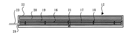
図1は、本発明の断熱保温ユニット、支持カバー及び外部カバーを含む断熱保温用具キットを配管に装着した断熱保温構造の断面の説明図である。
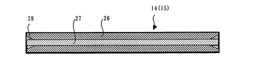
図2は、断熱保温ユニットの内部構成例の説明図である。
図3は、支持カバー及び外部カバーのスリット状開口部の両管端角部の切り欠き形状例の説明図である。
図4は、本発明の断熱保温用キットおよび断熱保温構造の各構成要素である断熱保温ユニット、支持カバー及び外部カバーを配管に装着する手順の説明図である。
図5は、本発明の断熱保温用キットおよび断熱保温構造の各構成要素である断熱保温ユニット、支持カバー及び外部カバーを配管に装着する他の手順の説明図である。
Embodiments of the present invention will be specifically described with reference to the drawings.
FIG. 1 is an explanatory view of a cross section of a heat insulation structure in which a heat insulation tool kit including a heat insulation unit, a support cover and an external cover according to the present invention is attached to a pipe.
FIG. 2 is an explanatory diagram of an internal configuration example of the heat insulation and heat insulation unit.
FIG. 3 is an explanatory diagram of an example of a cutout shape of both tube end corners of the slit-like opening of the support cover and the outer cover.
FIG. 4 is an explanatory diagram of a procedure for mounting a heat insulation and heat insulation unit, a support cover, and an external cover, which are components of the heat insulation and heat insulation kit and the heat insulation structure of the present invention, to a pipe.
FIG. 5 is an explanatory diagram of another procedure for mounting a heat insulation and heat insulation unit, a support cover, and an external cover, which are components of the heat insulation and heat insulation kit and the heat insulation structure of the present invention, to a pipe.
この実施形態は、加熱すべき配管11として、ステンレススチール製の外径6.35mm、長さ30cmの配管部分を対象とし、それに適する断熱保温用キットを準備し、断熱保温構造10の一例を形成する。帯状基材16として厚さ1.5mm、幅20mm、長さ296mmのガラス繊維テープ16を使用し、その加熱側表面に、長さ約1200mm、シリカスリーブ絶縁した100ワットのニクロム線(NCH−2、日本金属工業株式会社製)17をガラス繊維テープ16の長さ方向に平行に4回蛇行させて配置し、ニクロム線17の長さに沿って50mm毎にガラスヤーン18でガラス繊維テープ16に巻き縫いし、ニクロム線17の両端を、末端にオス型プラグがキットされている絶縁被覆した外部電力供給線23に接続した。
In this embodiment, as a
この外部電力供給線23以外の部分の全体を均熱材料19としての厚さ0.1mmのアルミニウム箔19を二重にして被包し、その被包体の外側でニクロム線17が配置されている加熱面側中央部に、φ0.32mmのK熱電対の熱電対接合部21を配置し、その絶縁されたリード線(図示省略)の先端が上記のニクロム線17の引き出し口24に並ぶように配置し、リード線を前記のニクロム線の場合と同様にガラスヤーンを使用して上記のガラス繊維テープ16にアルミニウム箔層19を貫通して巻き縫いすることにより固定し、また上記の加熱面の裏面に、背面断熱層20として厚さ3mm、幅20mm、長さ296mmのPTFE多孔質シート20を重ねた。
The entire portion other than the external
そして、その全体を、被包材料22としての厚さ0.1mm、幅36mm、長さ300mmのPTFEフイルム22の2枚の間の中央部に配置し、帯状基材16位置の幅方向の両端側の各8mm、長さ方向の両端の各2mm部分に熱融着用材料として厚さ0.1mmのPFAフイルムを挟み、360℃に加熱した熱板で上下より圧着して封着した。その結果、幅方向の両辺縁部にそれぞれ幅8mmの耳部13を具備した断熱保温部の厚さが約5mmの断熱保温ユニット12を得た。
And the whole is arrange | positioned in the center part between two sheets of the
内径20mm、外径23mm(肉厚1.5mm)、長さ300mmのPFA樹脂製チューブの外周面を長さ方向に沿ってスリット状に切り欠いて、静置状態で内径16mm、外径19mm(肉厚1.5mm)、開口部幅27が5mmのものを得、次いで、その長さ方向の両管端角部を、図3に示すように、長さ方向10mm、末端円周方向に5mmの3角形部分28を切り欠いて開口幅を広幅15mmとした。辺縁部の切断面は角部を滑らかに研磨して、支持カバー14を得た。また、別に、長さを150mmとした以外は、支持カバー14の場合と同様にして、静置状態で開口部32の開口幅が5mm、管端角部28の開口幅が広幅15mmの外部カバー15を2つ作製し、以上合わせて断熱保温ユニット12を1つ、支持カバー14を1本および外部カバー15を2本から成る断熱保温用キットを得た。
An outer peripheral surface of a PFA resin tube having an inner diameter of 20 mm, an outer diameter of 23 mm (thickness of 1.5 mm), and a length of 300 mm is cut out in a slit shape along the length direction, and the inner diameter is 16 mm and the outer diameter is 19 mm ( (Thickness of 1.5 mm) and an
図4に示した装着手順に沿って、まず、支持カバー14の開口部27を押し開きつつその管体内に断熱保温ユニット12を収容した。その際、断熱保温ユニット12の非加熱面が支持カバー14の内周面に沿わせるように且つ断熱保温ユニット12の断熱保温部12の幅方向の両端の突き合わせ部分が支持カバー14のスリット状開口部27から覗くように配置を調整し、当該断熱保温部の両端の耳部13をスリット状開口部27から引き出し、それぞれを支持カバー14の両外周面側に折り返した形態に調整する。次いで、上記のスリット状開口部27から覗く上記の突き合わせ部間を押し広げた状態でその間隙を外径6.35mmの配管11の長さ300mm部分に押し付け、支持カバー14の管体で配管を被装した。この被装操作の際、上記の耳部13の折り返し部が支持カバー14のスリット状開口部27の両辺縁に引っ掛かる機構により、支持カバー14内で断熱保温ユニット12が変位しないで被装操作が円滑に行われ、さらに両耳部13がスリット状開口部27の両辺縁と外部カバー15の内周面とで挟持されて、断熱保温ユニット12が安定して固定されていた。
In accordance with the mounting procedure shown in FIG. 4, first, the heat insulating and
次いで、上記の外部カバー15のうちの1つの開口部27を断熱保温ユニット12の両辺縁部の突き合わせ部および支持カバー14のスリット状開口部27とが重なった部分に向け、支持カバー14の場合と同じ要領で、断熱保温ユニット12の巻き付け部を被装している支持カバー14をまとめて外部カバー15で被装し、断熱保温ユニット12を配管11の表面にコンパクトに装着した。この外部カバー15を支持カバー14の長さ方向の片端側に寄せ、外部カバー15が被装していない部分に、残りの外部カバー15を同様に被装して、配管11および断熱保温ユニット12の外周面は支持カバー14および外部カバー15により全面が被覆されて、本発明の断熱保温構造10が形成された。
Next, in the case of the
上記の断熱保温構造10では、支持カバー14のスリット状開口部27から突出した断熱保温ユニット12の両耳部13が支持カバー14の外周面と外部カバー15の内面との間に挟持されて断熱保温ユニット12は安定した形態で固定され、且つ断熱保温ユニット12の加熱面は背面側からの支持カバー14の内周面および外部カバー15の内周面側からの押圧力により配管11の外周面に圧接された構造となっている。そして、装着した断熱保温ユニット12の外部電力供給線25を、熱電対21のリード線を温度制御装置に接続して稼働したところ断熱保温ユニット12のニクロム線17からの発熱は圧接された配管11の外周面に効率よく伝導し、断熱保温ユニット12の過熱がなく且つ安定した温度制御が可能であった。
In the heat insulation and
10:断熱保温構造
11:配管
12:断熱保温ユニット(断熱保温部)
13:断熱保温ユニットの耳部
14:支持カバー
15:外部カバー
16:帯状基材(ガラス繊維テープ)
17:断熱保温ユニット内のニクロム線
18:ニクロム線固定用縫糸(ガラスヤーン)
19:均熱材料(アルミニウム箔)
20:背面断熱材料
21:熱電対
22:被包材料
23:外部電力供給線
24:外部電力供給線引出口
25:支持カバー及び外部カバーの外観
26:支持カバー及び外部カバーの外周面
27:スリット状開口部切り欠き部
28:管端角部の切り欠き部
10: Heat insulation structure 11: Piping 12: Heat insulation unit (heat insulation part)
13:
17: Nichrome wire in heat insulation unit 18: Nichrome wire fixing thread (glass yarn)
19: Soaking material (aluminum foil)
20: Rear heat insulating material 21: Thermocouple 22: Encapsulating material 23: External power supply line 24: External power supply line outlet 25: Appearance of support cover and external cover 26: Outer
Claims (13)
Priority Applications (6)
| Application Number | Priority Date | Filing Date | Title |
|---|---|---|---|
| JP2003339079A JP4418201B2 (en) | 2003-09-30 | 2003-09-30 | Insulated heat insulation structure of piping and heat insulation tool kit |
| TW093127759A TW200525107A (en) | 2003-09-30 | 2004-09-14 | Heat insulating construction for piping and heat insulating tool kit |
| KR1020040076107A KR20050031904A (en) | 2003-09-30 | 2004-09-22 | Heat insulating structure of piping and heat insulating tool kit |
| EP04022905A EP1521030A1 (en) | 2003-09-30 | 2004-09-25 | Heat insulating construction for piping and heat insulating tool kit |
| US10/949,520 US20050067038A1 (en) | 2003-09-30 | 2004-09-27 | Heat insulating construction for piping and heat insulating tool kit |
| CNA2004100120423A CN1603675A (en) | 2003-09-30 | 2004-09-28 | Heat insulating construction for piping and heat insulating tool kit |
Applications Claiming Priority (1)
| Application Number | Priority Date | Filing Date | Title |
|---|---|---|---|
| JP2003339079A JP4418201B2 (en) | 2003-09-30 | 2003-09-30 | Insulated heat insulation structure of piping and heat insulation tool kit |
Publications (2)
| Publication Number | Publication Date |
|---|---|
| JP2005106145A true JP2005106145A (en) | 2005-04-21 |
| JP4418201B2 JP4418201B2 (en) | 2010-02-17 |
Family
ID=34309004
Family Applications (1)
| Application Number | Title | Priority Date | Filing Date |
|---|---|---|---|
| JP2003339079A Expired - Lifetime JP4418201B2 (en) | 2003-09-30 | 2003-09-30 | Insulated heat insulation structure of piping and heat insulation tool kit |
Country Status (6)
| Country | Link |
|---|---|
| US (1) | US20050067038A1 (en) |
| EP (1) | EP1521030A1 (en) |
| JP (1) | JP4418201B2 (en) |
| KR (1) | KR20050031904A (en) |
| CN (1) | CN1603675A (en) |
| TW (1) | TW200525107A (en) |
Cited By (4)
| Publication number | Priority date | Publication date | Assignee | Title |
|---|---|---|---|---|
| JP2009287668A (en) * | 2008-05-29 | 2009-12-10 | Panasonic Electric Works Co Ltd | Heat insulating material |
| JP2014007111A (en) * | 2012-06-26 | 2014-01-16 | Nichias Corp | Heater and heat transfer member |
| CN105050213A (en) * | 2015-07-13 | 2015-11-11 | 四会市生料带厂有限公司 | Teflon electrothermal tube |
| JP7454927B2 (en) | 2019-08-08 | 2024-03-25 | ニチアス株式会社 | Heat insulation cover for flexible pipes, method for manufacturing heat insulation pipes and heat insulation covers for flexible pipes |
Families Citing this family (30)
| Publication number | Priority date | Publication date | Assignee | Title |
|---|---|---|---|---|
| US7152633B2 (en) * | 2003-09-17 | 2006-12-26 | Thermo-Tec | Heat shield |
| US7842396B2 (en) * | 2004-10-29 | 2010-11-30 | Thermo-Tec Automotive Products, Inc. | Air cooled heat shield |
| JP2006175682A (en) * | 2004-12-21 | 2006-07-06 | Tokai Rubber Ind Ltd | Low permeable composite hose |
| DE202006010637U1 (en) * | 2006-07-10 | 2006-08-31 | Saint-Gobain Isover G+H Ag | Insulating material for wall, deck or roof opening includes tube shell having fibers that are two-dimensionally oriented |
| KR100972679B1 (en) * | 2008-02-15 | 2010-07-27 | 오재영 | A manufacturing and heating jacket for pipeline gas refined of semiconductor fabrication |
| US20110011757A1 (en) * | 2009-06-26 | 2011-01-20 | Uhl Fawn M | Energy efficiency improvement kits |
| KR101462325B1 (en) * | 2010-04-06 | 2014-11-14 | 니찌아스 카부시키카이샤 | Jacket heater and method for attaching same |
| DE102010026827A1 (en) * | 2010-07-12 | 2012-01-12 | Daimler Ag | Device for connecting a line element to a component |
| DE202010016709U1 (en) * | 2010-12-17 | 2012-03-19 | Isolite Gmbh | Elastic thermal insulation module |
| DE102011016170A1 (en) * | 2011-04-05 | 2012-10-11 | Faurecia Emissions Control Technologies, Germany Gmbh | Exhaust gas device and method for its production |
| KR200469807Y1 (en) * | 2011-04-22 | 2013-11-07 | 주식회사 디엔디 | Heating jacket to enhance heating efficiency |
| CN102330851A (en) * | 2011-07-26 | 2012-01-25 | 广东联塑科技实业有限公司 | Water supply piping material with electric heating film and production process of same |
| KR101318451B1 (en) * | 2011-09-19 | 2013-10-15 | 박화섭 | Rubber Lagging Material, Heating Apparatus and Manufacturing Method of Heating Apparatus |
| CN102490995A (en) * | 2011-11-28 | 2012-06-13 | 南车成都机车车辆有限公司 | Winter protection method for locomotive vehicle |
| KR200459980Y1 (en) * | 2011-12-23 | 2012-04-25 | 김지안 | Heat tracing carrier |
| US20150027747A1 (en) * | 2012-01-27 | 2015-01-29 | E I Du Pont De Nemours And Company | Foam insulated conductors |
| WO2014103981A1 (en) * | 2012-12-25 | 2014-07-03 | 株式会社クラベ | Cord-shaped heater and sheet-shaped heater |
| WO2014131127A1 (en) * | 2013-02-28 | 2014-09-04 | Shawcor Ltd. | High temperature resistant polysulfone insulation for pipe |
| JP6224366B2 (en) | 2013-07-12 | 2017-11-01 | 東京エレクトロン株式会社 | Support member and substrate processing apparatus |
| JP2015069931A (en) | 2013-09-30 | 2015-04-13 | ニチアス株式会社 | Jacket heater |
| JP6348696B2 (en) | 2013-09-30 | 2018-06-27 | ニチアス株式会社 | Tape heater |
| US9855696B2 (en) * | 2013-11-25 | 2018-01-02 | Commscope, Inc. Of North Carolina | Aerial integrated messenger conduit |
| GB201321920D0 (en) * | 2013-12-11 | 2014-01-22 | British American Tobacco Co | A method and apparatus for inserting elongate elements into a sleeve |
| DE102014209826A1 (en) * | 2014-05-23 | 2015-11-26 | Contitech Ag | Insulating element or insulating system for sheathing a body |
| JP6616265B2 (en) | 2015-10-16 | 2019-12-04 | 株式会社Kokusai Electric | Heating unit, substrate processing apparatus, and semiconductor device manufacturing method |
| US10011155B2 (en) * | 2016-03-11 | 2018-07-03 | Ford Global Technologies Llc | Nested HVAC lines |
| US11009170B2 (en) | 2017-02-16 | 2021-05-18 | Nichias Corporation | Thermally conductive cover for piping system, heating device for piping system, manufacturing method and attachment method for thermally conductive cover, and manufacturing method and attachment method for heating device |
| KR102119597B1 (en) | 2019-09-24 | 2020-06-05 | 김상범 | Pipe insulation for manufacturing device of semiconductor and display panel |
| US20230010222A1 (en) * | 2021-07-12 | 2023-01-12 | The Boeing Company | Ducts comprising exoskeleton and sound-absorbing structures and vehicles using such ducts |
| CN113883340B (en) * | 2021-08-30 | 2023-05-12 | 合肥友孚热能装备制造有限公司 | Flexible protection unit for pipeline anti-freezing leak detection |
Family Cites Families (18)
| Publication number | Priority date | Publication date | Assignee | Title |
|---|---|---|---|---|
| DE1722010U (en) * | 1955-12-23 | 1956-05-09 | Alkett Maschb G M B H | PIPE INSULATION. |
| DE1170208B (en) * | 1958-05-10 | 1964-05-14 | Westaflex G M B H | Protection tube for a thermal insulation |
| GB910237A (en) * | 1959-10-23 | 1962-11-14 | Isopad Ltd | Improvements in or relating to thermal lagging means for pipes |
| US3727029A (en) * | 1964-07-01 | 1973-04-10 | Moore & Co Samuel | Composite electrically heated tubing product |
| DE2153392A1 (en) * | 1971-10-27 | 1973-05-03 | Linde Ag | METHOD OF MANUFACTURING PIPE INSULATION |
| DE2247342A1 (en) * | 1972-09-27 | 1974-03-28 | Peter Trieb | METHOD FOR THERMAL INSULATION OF PIPELINES |
| US3955601A (en) * | 1972-11-29 | 1976-05-11 | Moore Business Forms, Inc. | Heat insulating jacket for a conduit equipped with self-locking seam |
| US4015636A (en) * | 1975-12-04 | 1977-04-05 | The Babcock & Wilcox Company | Ceramic refractory covering members |
| US4194536A (en) * | 1976-12-09 | 1980-03-25 | Eaton Corporation | Composite tubing product |
| US4228826A (en) * | 1978-10-12 | 1980-10-21 | Campbell Frank Jun | Interlocking, laminated refractory for covering a pipe |
| US4429213A (en) * | 1978-10-20 | 1984-01-31 | Dayco Corporation | Electrically heated fluid conduit |
| US4874925A (en) * | 1987-06-01 | 1989-10-17 | Dickenson Wilk A | Electrically heated hose assembly for conveying electrically conductive liquids |
| BR9401650A (en) * | 1994-04-29 | 1995-11-21 | Maria Eliane Almeida | Improved system for fixing thermal insulation in pipes and the like |
| BR9403801A (en) * | 1994-09-21 | 1995-03-07 | De Oliveira Murilio Pessoa | Isolation and fixation system of steam traces in fluid transport pipes |
| US5883363A (en) * | 1996-08-12 | 1999-03-16 | Nichias Corporation | Heating mantle and method for fabricating the same |
| IL120155A (en) * | 1997-02-05 | 2000-08-13 | Isoltherm A P Ltd | Heat insulating covering and method |
| US5947158A (en) * | 1998-07-28 | 1999-09-07 | Johns Manville International, Inc. | Flexible insulated duct and the method of making the duct |
| AU2003268439A1 (en) * | 2002-09-04 | 2004-03-29 | Knauf Insulation Gmbh | Pipe blanket to fit a variety of pipe diameters |
-
2003
- 2003-09-30 JP JP2003339079A patent/JP4418201B2/en not_active Expired - Lifetime
-
2004
- 2004-09-14 TW TW093127759A patent/TW200525107A/en unknown
- 2004-09-22 KR KR1020040076107A patent/KR20050031904A/en not_active Application Discontinuation
- 2004-09-25 EP EP04022905A patent/EP1521030A1/en not_active Withdrawn
- 2004-09-27 US US10/949,520 patent/US20050067038A1/en not_active Abandoned
- 2004-09-28 CN CNA2004100120423A patent/CN1603675A/en active Pending
Cited By (4)
| Publication number | Priority date | Publication date | Assignee | Title |
|---|---|---|---|---|
| JP2009287668A (en) * | 2008-05-29 | 2009-12-10 | Panasonic Electric Works Co Ltd | Heat insulating material |
| JP2014007111A (en) * | 2012-06-26 | 2014-01-16 | Nichias Corp | Heater and heat transfer member |
| CN105050213A (en) * | 2015-07-13 | 2015-11-11 | 四会市生料带厂有限公司 | Teflon electrothermal tube |
| JP7454927B2 (en) | 2019-08-08 | 2024-03-25 | ニチアス株式会社 | Heat insulation cover for flexible pipes, method for manufacturing heat insulation pipes and heat insulation covers for flexible pipes |
Also Published As
| Publication number | Publication date |
|---|---|
| EP1521030A1 (en) | 2005-04-06 |
| TW200525107A (en) | 2005-08-01 |
| KR20050031904A (en) | 2005-04-06 |
| CN1603675A (en) | 2005-04-06 |
| JP4418201B2 (en) | 2010-02-17 |
| US20050067038A1 (en) | 2005-03-31 |
Similar Documents
| Publication | Publication Date | Title |
|---|---|---|
| JP4418201B2 (en) | Insulated heat insulation structure of piping and heat insulation tool kit | |
| JP5602219B2 (en) | Jacket heater and mounting method thereof | |
| KR20040086756A (en) | Tape heater | |
| TWI580302B (en) | Heating sets | |
| TWI532943B (en) | A jacket heater and a heating method using the same | |
| JP4319537B2 (en) | Piping heater | |
| KR20220113432A (en) | heater assembly | |
| JP2010097809A (en) | Electrothermal heater | |
| JP2009037885A (en) | Tape heater, and structure of tape heater | |
| JPH1064667A (en) | Mantle heater | |
| JP4744504B2 (en) | Coating heating device | |
| JP5894632B2 (en) | Heating device | |
| TWI461092B (en) | Plane heater | |
| JP4071599B2 (en) | Coating heater | |
| KR102276204B1 (en) | Temperature sensing device and fluid line heating jacket with the same | |
| KR101293292B1 (en) | Methods for forming pipe-shaped insulator and fabricating heater jacket including pipe-shaped insulator | |
| JP2935014B2 (en) | Water pipe freezing prevention device | |
| JP2023002984A (en) | Sheet-like heater | |
| JP4278092B2 (en) | Pipe fitting | |
| JP2003333803A (en) | Overheat preventing device for motor | |
| JP2005121109A (en) | Hose with heating/insulating function and jacket for hose using the same | |
| JP2015232991A (en) | Tape heating body for piping | |
| JPH11211384A (en) | Heat conveying device |
Legal Events
| Date | Code | Title | Description |
|---|---|---|---|
| A621 | Written request for application examination |
Free format text: JAPANESE INTERMEDIATE CODE: A621 Effective date: 20060913 |
|
| A977 | Report on retrieval |
Free format text: JAPANESE INTERMEDIATE CODE: A971007 Effective date: 20090427 |
|
| A131 | Notification of reasons for refusal |
Free format text: JAPANESE INTERMEDIATE CODE: A131 Effective date: 20090519 |
|
| A521 | Request for written amendment filed |
Free format text: JAPANESE INTERMEDIATE CODE: A523 Effective date: 20090717 |
|
| TRDD | Decision of grant or rejection written | ||
| A01 | Written decision to grant a patent or to grant a registration (utility model) |
Free format text: JAPANESE INTERMEDIATE CODE: A01 Effective date: 20091117 |
|
| A01 | Written decision to grant a patent or to grant a registration (utility model) |
Free format text: JAPANESE INTERMEDIATE CODE: A01 |
|
| A61 | First payment of annual fees (during grant procedure) |
Free format text: JAPANESE INTERMEDIATE CODE: A61 Effective date: 20091127 |
|
| R150 | Certificate of patent or registration of utility model |
Ref document number: 4418201 Country of ref document: JP Free format text: JAPANESE INTERMEDIATE CODE: R150 Free format text: JAPANESE INTERMEDIATE CODE: R150 |
|
| FPAY | Renewal fee payment (event date is renewal date of database) |
Free format text: PAYMENT UNTIL: 20121204 Year of fee payment: 3 |
|
| FPAY | Renewal fee payment (event date is renewal date of database) |
Free format text: PAYMENT UNTIL: 20121204 Year of fee payment: 3 |
|
| FPAY | Renewal fee payment (event date is renewal date of database) |
Free format text: PAYMENT UNTIL: 20121204 Year of fee payment: 3 |
|
| FPAY | Renewal fee payment (event date is renewal date of database) |
Free format text: PAYMENT UNTIL: 20131204 Year of fee payment: 4 |
|
| R250 | Receipt of annual fees |
Free format text: JAPANESE INTERMEDIATE CODE: R250 |
|
| S531 | Written request for registration of change of domicile |
Free format text: JAPANESE INTERMEDIATE CODE: R313531 |
|
| R350 | Written notification of registration of transfer |
Free format text: JAPANESE INTERMEDIATE CODE: R350 |
|
| R250 | Receipt of annual fees |
Free format text: JAPANESE INTERMEDIATE CODE: R250 |
|
| R250 | Receipt of annual fees |
Free format text: JAPANESE INTERMEDIATE CODE: R250 |
|
| R250 | Receipt of annual fees |
Free format text: JAPANESE INTERMEDIATE CODE: R250 |
|
| R250 | Receipt of annual fees |
Free format text: JAPANESE INTERMEDIATE CODE: R250 |
|
| R250 | Receipt of annual fees |
Free format text: JAPANESE INTERMEDIATE CODE: R250 |
|
| R250 | Receipt of annual fees |
Free format text: JAPANESE INTERMEDIATE CODE: R250 |
|
| R250 | Receipt of annual fees |
Free format text: JAPANESE INTERMEDIATE CODE: R250 |
|
| R250 | Receipt of annual fees |
Free format text: JAPANESE INTERMEDIATE CODE: R250 |
|
| R250 | Receipt of annual fees |
Free format text: JAPANESE INTERMEDIATE CODE: R250 |
|
| R250 | Receipt of annual fees |
Free format text: JAPANESE INTERMEDIATE CODE: R250 |
|
| EXPY | Cancellation because of completion of term |