JP2005103929A - Apparatus for forming small printed matter, method for forming small printed matter and program for forming small printed matter - Google Patents
Apparatus for forming small printed matter, method for forming small printed matter and program for forming small printed matter Download PDFInfo
- Publication number
- JP2005103929A JP2005103929A JP2003340290A JP2003340290A JP2005103929A JP 2005103929 A JP2005103929 A JP 2005103929A JP 2003340290 A JP2003340290 A JP 2003340290A JP 2003340290 A JP2003340290 A JP 2003340290A JP 2005103929 A JP2005103929 A JP 2005103929A
- Authority
- JP
- Japan
- Prior art keywords
- ruled
- printed matter
- small printed
- rule
- frame
- Prior art date
- Legal status (The legal status is an assumption and is not a legal conclusion. Google has not performed a legal analysis and makes no representation as to the accuracy of the status listed.)
- Pending
Links
Images


Classifications
-
- B—PERFORMING OPERATIONS; TRANSPORTING
- B41—PRINTING; LINING MACHINES; TYPEWRITERS; STAMPS
- B41J—TYPEWRITERS; SELECTIVE PRINTING MECHANISMS, i.e. MECHANISMS PRINTING OTHERWISE THAN FROM A FORME; CORRECTION OF TYPOGRAPHICAL ERRORS
- B41J3/00—Typewriters or selective printing or marking mechanisms characterised by the purpose for which they are constructed
- B41J3/407—Typewriters or selective printing or marking mechanisms characterised by the purpose for which they are constructed for marking on special material
- B41J3/4075—Tape printers; Label printers
-
- B—PERFORMING OPERATIONS; TRANSPORTING
- B41—PRINTING; LINING MACHINES; TYPEWRITERS; STAMPS
- B41J—TYPEWRITERS; SELECTIVE PRINTING MECHANISMS, i.e. MECHANISMS PRINTING OTHERWISE THAN FROM A FORME; CORRECTION OF TYPOGRAPHICAL ERRORS
- B41J5/00—Devices or arrangements for controlling character selection
- B41J5/30—Character or syllable selection controlled by recorded information
-
- Y—GENERAL TAGGING OF NEW TECHNOLOGICAL DEVELOPMENTS; GENERAL TAGGING OF CROSS-SECTIONAL TECHNOLOGIES SPANNING OVER SEVERAL SECTIONS OF THE IPC; TECHNICAL SUBJECTS COVERED BY FORMER USPC CROSS-REFERENCE ART COLLECTIONS [XRACs] AND DIGESTS
- Y10—TECHNICAL SUBJECTS COVERED BY FORMER USPC
- Y10T—TECHNICAL SUBJECTS COVERED BY FORMER US CLASSIFICATION
- Y10T428/00—Stock material or miscellaneous articles
- Y10T428/14—Layer or component removable to expose adhesive
- Y10T428/149—Sectional layer removable
- Y10T428/1495—Adhesive is on removable layer
Abstract
Description
本発明は、小印刷物作成装置、小印刷物作成方法及び小印刷物作成プログラムに関し、例えば、専用のテープ印刷装置や、パソコンとラベルプリンタとが結合されたテープ印刷システムや、専用のスタンプ(印章)作成装置や、パソコンとスタンプ作成用周辺装置とが結合されたスタンプ作成システムなどに適用し得るものである。 The present invention relates to a small printed matter creating apparatus, a small printed matter creating method, and a small printed matter creating program. For example, a dedicated tape printer, a tape printing system in which a personal computer and a label printer are combined, and a dedicated stamp (stamp) creation. The present invention can be applied to a device or a stamp creation system in which a personal computer and a stamp creation peripheral device are combined.
例えば、専用のテープ印刷装置は、入力された文字(記号、絵文字、外枠、地紋等を含む概念とする)の列を連続するテープに必要に応じて印刷すると共に、印刷されたテープを排出して切断するものである。このような切断後の文字列が印刷されたテープはラベルと呼ばれている。 For example, a dedicated tape printer prints a string of input characters (concepts including symbols, pictograms, outer frame, background pattern, etc.) on continuous tape as necessary, and ejects the printed tape. And cut. Such a tape on which a character string after cutting is printed is called a label.
以上のように、テープ印刷装置での印刷物はラベルとして用いられるため、一般的な印刷物に比較し、その印刷内容に装飾が施されることが多い。そのため、テープ印刷装置は、装飾機能が充実している。 As described above, since the printed matter in the tape printer is used as a label, the printed content is often decorated as compared with a general printed matter. For this reason, the tape printer has a rich decoration function.
特許文献1には、入力文字列を囲繞する外枠のうち、前罫部分(縦書きであれば上罫部分が該当する)及び後罫部分(縦書きであれば下罫部分が該当する)について、線ではなく、図形などを印刷する技術が開示されている。なお、本明細書においては、横書き外枠や横書き表組の前罫部分、及び、縦書き外枠や縦書き表組の上罫部分を併せて、適宜「前罫部分」と呼び、また、横書き外枠や横書き表組の後罫部分、及び、縦書き外枠や縦書き表組の下罫部分を併せて、適宜「後罫部分」と呼ぶことにする。
In
また、特許文献2には、入力文字列を囲繞する外枠罫線部分を、線ではなく、指定された1又は複数の文字を小さくして線状に配置して印刷する技術が開示されている。
しかしながら、特許文献1記載の従来装置では、外枠の前罫部分及び後罫部分になり得る図形などの組は、予め装置に用意されているものに限定され、ユーザが選択し得る幅が狭いという課題を有するものであった。また、前罫部分の図形と後罫部分の図形とは組をなしており、組単位で選択する他なく、この点でも、外枠の前罫部分及び後罫部分のパターンが限定されていた。選択し得る幅を広げようとすると、外枠の前罫部分及び後罫部分になり得る図形などの組を、装置が多数記憶しておかなければならず、メモリ素子が多くなって装置を大型化する恐れがある。
However, in the conventional device described in
特許文献2記載の従来装置では、外枠の罫線となる部分の線状に配置される文字を任意に選択できるが、線としての選択であるため、前罫部分及び後罫部分に図形を配置した場合の修飾効果よりは、修飾効果が小さいという課題を有する。
In the conventional device described in
そのため、予め記憶している情報量を増やすことなく、外枠や表組における枠要素図形として、多様なものを適用可能な小印刷物作成装置、小印刷物作成方法及び小印刷物作成プログラムが望まれている。 Therefore, there is a demand for a small printed material creating apparatus, a small printed material creating method, and a small printed material creating program that can apply various kinds of frame element figures in an outer frame and a table set without increasing the amount of information stored in advance. Yes.
かかる課題を解決するため、第1の本発明の小印刷物作成装置は、数行程度の入力文字列に対し、少なくとも前罫、後罫、上罫、下罫の要素を含む枠形状の付与機能を有するものであって、(1)少なくとも上記前罫要素及び又は上記後罫要素として、上記入力文字列の文字要素として入力し得るものから任意の1文字を指定させる枠要素任意指定手段と、(2)印刷指令時に、上記枠要素任意指定手段によって任意指定された文字要素を、上記前罫要素及び又は上記後罫要素としてドット展開する任意枠要素展開手段とを有することを特徴とする。 In order to solve this problem, the small printed matter creating apparatus according to the first aspect of the present invention provides a frame shape adding function including at least front ruled, rear ruled, upper ruled, and lower ruled elements for an input character string of several lines. (1) a frame element arbitrary designation means for designating any one character from those that can be input as a character element of the input character string as at least the front ruled element and / or the rear ruled element; (2) An arbitrary frame element expansion unit that expands a character element arbitrarily designated by the frame element arbitrary designation unit at the time of a print command as the preceding ruled element or the rear ruled element.
また、第2の本発明の小印刷物作成方法は、数行程度の入力文字列に対し、少なくとも前罫、後罫、上罫、下罫の要素を含む枠形状の付与機能を有するものであって、(1)少なくとも上記前罫要素及び又は上記後罫要素として、上記入力文字列の文字要素として入力し得るものから任意の1文字を指定させる枠要素任意指定工程と、(2)印刷指令時に、上記枠要素任意指定工程によって任意指定された文字要素を、上記前罫要素及び又は上記後罫要素としてドット展開する任意枠要素展開工程とを含むことを特徴とする。 Further, the small printed matter creating method of the second aspect of the present invention has a function of giving a frame shape including elements of at least a front rule, a rear rule, an upper rule, and a lower rule to an input character string of about several lines. (1) a frame element arbitrary designation step for designating any one character from those that can be input as character elements of the input character string as at least the front ruled element and / or the rear ruled element; and (2) a print command. In some cases, the method includes an arbitrary frame element expanding step of dot-expanding the character element arbitrarily specified in the frame element arbitrary specifying step as the front ruled element and / or the rear ruled element.
第3の本発明の小印刷物作成プログラムは、第2の本発明の小印刷物作成方法の各工程をコンピュータが実行可能なコードで記述していることを特徴とする。 The small printed matter creation program of the third aspect of the present invention is characterized in that each step of the small printed matter creation method of the second aspect of the present invention is described by a computer executable code.
本発明によれば、枠形状の前罫要素及び又は後罫要素として、入力文字列の文字要素として入力し得るものを指定させ、そのような文字要素を枠要素とした枠形状を印刷可能としたので、予め記憶している情報量を増やすことなく、外枠や表組における枠要素図形として、多様なものを適用可能な小印刷物作成装置、小印刷物作成方法及び小印刷物作成プログラムを実現することができる。 According to the present invention, it is possible to designate what can be input as a character element of an input character string as a front rule element and / or a rear rule element of a frame shape, and print a frame shape using such a character element as a frame element. Therefore, it is possible to realize a small printed material creating apparatus, a small printed material creating method, and a small printed material creating program that can apply a variety of frame element figures in an outer frame and a table without increasing the amount of information stored in advance. be able to.
(A)一実施形態
以下、本発明による小印刷物作成装置、小印刷物作成方法及び小印刷物作成プログラムを、テープ印刷装置、テープ印刷方法及びテープ印刷プログラムに適用した一実施形態を図面を参照しながら詳述する。
(A) One Embodiment Hereinafter, an embodiment in which a small printed material creating apparatus, a small printed material creating method, and a small printed material creating program according to the present invention are applied to a tape printer, a tape printing method, and a tape printing program will be described with reference to the drawings. Detailed description.
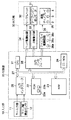
まず、この実施形態のテープ印刷装置の電気的な全体構成を、図1の機能ブロック図を用いて説明する。なお、この実施形態のテープ印刷装置は、ラベル作成の専用機として構築されているものである。 First, the overall electrical configuration of the tape printer of this embodiment will be described with reference to the functional block diagram of FIG. The tape printer of this embodiment is constructed as a dedicated machine for label production.
図1において、実施形態のテープ印刷装置は、大きくは、入力部10、制御部20及び出力部30から構成されており、制御部20が、入力部10からの情報やその時点の処理段階等に応じた処理を実行し、その処理結果等を出力部30によって表示出力又は印刷出力させるようになされている。
In FIG. 1, the tape printing apparatus according to the embodiment mainly includes an
入力部10は、詳細の構成は省略するが押下キー(やダイヤルキー)を備えたキー入力部11や、テープ幅検出センサ12を有する。キー入力部11は、制御部20に与える文字コードや各種の制御データを発生するものである。テープ幅検出センサ12は、装填されているテープの幅を検出してテープ幅情報を制御部20に与えるものである。実際上、テープはテープカートリッジに収納されており、テープカートリッジにはテープ幅を規定する孔等の物理的な識別要素が設けられており、テープ幅検出センサ12はこの物理的な識別要素を読み取ってテープ幅情報を出力する。キー入力部11には、外枠や表組の付与処理を起動するキー(専用キーでも良く、ファンクションキーなどと共に用いられる兼用キーでも良い)や、記号選択処理を起動するキー(専用キーでも良く、ファンクションキーなどと共に用いられる兼用キーでも良い)が設けられている。
Although the detailed configuration is omitted, the
出力部30は、印刷構成と表示構成からなる。例えばステッピングモータや直流モータ等でなるテープ・リボン送りモータ31は、装填されている図示しないテープやインクリボンを所定の印刷位置や装置外部まで送り出すものであり、印刷ヘッド(ここではサーマルヘッドとする)32は例えば固定されていて、走行するテープに対して熱転写によって印刷を行なうものである。これらテープ・リボン送りモータ31及びサーマルヘッド32はそれぞれ、制御部20の制御下で、モータ駆動回路33やヘッド駆動回路34によって駆動される。印刷されたテープの切断は、例えば、ユーザからの外力又はモータによって駆動される図示しないカッタによって行なわれる。
The output unit 30 includes a printing configuration and a display configuration. For example, a tape / ribbon feed motor 31 formed of a stepping motor, a direct current motor, or the like feeds a tape or ink ribbon (not shown) loaded to a predetermined printing position or outside the apparatus, and is a print head (here, a thermal head). 32) is fixed, for example, and prints on the running tape by thermal transfer. The tape / ribbon feed motor 31 and the
このテープ印刷装置の表示部として、例えば所定サイズの文字を数行(例えば1行)に渡って数文字(例えば6文字)程度表示できる程度の液晶ディスプレイ35が設けられており、この液晶ディスプレイ35は、制御部20の制御下でディスプレイ駆動回路36によって駆動される。
As a display unit of the tape printer, for example, a
液晶ディスプレイ35の表示面は、図示は省略するが、入力文字列及び又は印刷イメージなどを表示する文字表示領域、入力文字列の行数やカーソルが一している行に応じて点灯制御される行番号インジケータと、入力文字列に係る各種の属性等を表す属性インジケータとを有する。属性インジケータは、そのオン表示が、その属性インジケータに対応した表示面の周囲に記載されている文字が表す属性が採用されていることを表すものである。属性インジケータが指示する属性としては、文字サイズについてのものや、かな入力やローマ字入力等の入力方式についてのものや、テープ長さ等を自動設定するなどの文字列全体(以下、文章と呼ぶ)を単位としたものや、たて書等の文字列のある程度のかたまり(以下、段落)を単位としたものや、装飾文字や英書体等の文字単位のものや、基本的な書式の採用有無を表すものなどがある。
Although not shown, the display surface of the
以上のように、液晶ディスプレイ35は、文字表示領域2、行番号インジケータ部3、及び、属性インジケータ部4でなるので、ディスプレイ駆動回路36も、大別すると、文字表示領域に対応した駆動部36a、行番号インジケータ部に対応した駆動部36b、及び、属性インジケータ部に対応した駆動部36cからなる。
As described above, since the
図1に戻って、制御部20は、例えばマイクロコンピュータによって構成されており、CPU21、ROM22、RAM23、キャラクタジェネレータROM(CG−ROM)24、入力インタフェース25及び出力インタフェース26がシステムバス27を介して接続されて構成されている。
Returning to FIG. 1, the
ROM22は、1又は複数個のROMチップでなり、ROM22には、各種の処理プログラムや、かな漢字変換用辞書データ等の固定データが格納されている。例えば、外枠・表組付与プログラム22aや印刷処理用プログラム22bが格納されている。
The
RAM23は、1又は複数個のRAMチップでなり、ワーキングメモリとして用いられるものであり、また、ユーザ入力に係る固定データ等も格納するものである。図1では、RAM23として記載しているが、ワーキングメモリとして用いられるEEPROM等の他のメモリ素子を含む概念とする。RAM23は、印刷する文字列をドット展開して格納する印刷バッファや、入力文字列などについての表示画像を格納する表示バッファや、印刷や入力に係る文字データ等を格納するテキストバッファや、行番号インジケータについての表示態様を保持する行番号インジケータ状態保持バッファや、属性インジケータについての表示態様を保持する属性インジケータ状態保持バッファ等を有する。
The
CG−ROM24は、当該テープ印刷装置に用意されている文字や記号のドットパターンを格納しているものであり、文字を特定するコードデータが与えられたときに対応するドットパターンを出力するものである。なお、表示用と印刷用とで別個のCG−ROMが設けられていても良い。また、フォント情報の格納形式は、アウトラインフォント形式及びビットマップ形式のいずれであっても良いが、種々の大きさに対応し易いアウトラインフォント形式が好ましい。なお、外枠や表組の前罫部分や後罫部分に適用される専用の図形パターンの情報は、ROM22の固定データとして保持させておいても良く、CG−ROM24でのフォント情報の一部として保持させておいても良い。
The CG-
ここで、CG−ROM24によってフォントが用意されている、印刷し得る入力文字列に含むことができる文字は、大きくは、その入力方法の違いによって、2種類に大別することができる。第1種類は、ひらがな、カタカナ、英数字、漢字などの一般的な文字が該当し、キー入力部11に対する一般的な入力方法によって入力されるものである。第2種類は、記号が該当し、記号選択処理によって入力されるものである。ここでの記号とは、記号選択処理によって入力されるキャラクタを言い、一般的な記号だけでなく絵文字や丸付き数字等を含む概念である。例えば、キー入力部11における記号選択キーが操作されたときに、「ビデオ用」や「警告用」や「干支」などの記号種類を選択させるメニュー表示を行い、記号種類が選択されたときに、選択された記号種類に属する記号を選択させるメニュー表示させ(例えば、「干支」が選択されたときに、12種類の干支の動物図形(記号)を表示させ)、記号を選択させる。この具体的方法としては、既存のテープ印刷装置が適用している方法を適用できる。
Here, characters that can be included in an input character string that can be printed with fonts prepared by the CG-
入力インタフェース25は、入力部10及び制御部20間のインタフェースを行なうものであり、出力インタフェース26は、出力部30及び制御部20間のインタフェースを行なうものである。
The
CPU21は、入力部10からの入力信号やそのときの処理段階に応じて定まるROM22内の処理プログラムを、RAM23をワーキングエリアとして利用しながら、また、必要ならばROM22やRAM23に格納されている固定データを適宜用いて処理するものであり、その処理状況や処理結果等を液晶ディスプレイ35に表示させたり図示しないテープに印刷させたりするものである。
The
次に、この実施形態のテープ印刷装置の特徴動作(テープ印刷方法(小印刷物作成方法))を説明する。この実施形態は、外枠又は表組の入力動作(指定動作)に最も大きな特徴を有し、以下、この特徴動作を説明する。 Next, the characteristic operation (tape printing method (small printed matter creating method)) of the tape printer of this embodiment will be described. This embodiment has the greatest feature in the input operation (designated operation) of the outer frame or table, and this feature operation will be described below.
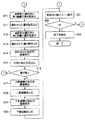
キー入力部11における外枠や表組の付与処理を起動するキーが操作されると、CPU21は、図2及び図3に示す処理(外枠・表組付与プログラム22a)を開始する。
When the key for starting the outer frame or table group assignment process in the
そしてまず、CPU21は、外枠を付与するのか表組を付与するのかをユーザに選択させる(S1)。ここで、外枠と表組との相違は、各行間の横罫(縦書きの縦罫)が存在するか否かであり、その点を除けば、ほぼ同様な処理であるので、以下では、外枠が選択された場合を例に説明する。
First, the
外枠を付与することが選択されると、CPU21は、付与する外枠の前罫部分及び後罫部分の図形パターンを選択させるパターン選択画像PIC1を、液晶ディスプレイ35に表示させ(S2)、図形パターンとして、装置用意パターンが選択されたか、ユーザ作成パターンが選択されたかを判別する(S3)。
When it is selected to add the outer frame, the
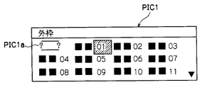
図4は、パターン選択画像PIC1の液晶ディスプレイ35の表示面に対する表示例を示す説明図である。
FIG. 4 is an explanatory diagram showing a display example of the pattern selection image PIC1 on the display surface of the
例えば、装置用意パターンの数は86である。これら各装置用意パターンのいずれかを選択させるための選択肢と、ユーザ作成パターンを選択させるための選択肢PIC1aとの計87個の選択肢を、パターン選択画像PIC1は有する。液晶ディスプレイ35の表示面の大きさとの関係から、パターン選択画像PIC1は、カーソル移動キーなどに応じた上下方向のスクロール処理により、一部分ずつを表示させる。ユーザ作成パターンを選択させるための選択肢PIC1aは、第1番目の位置の選択肢として用意されており、各装置用意パターンには、「01」〜「87」の識別番号が付与されている。なお、「00」という表示はなされていないが、ユーザ作成パターンを選択させるための選択肢PIC1aには、識別番号「00」が割り当てられている。デフォルトの選択肢は、例えば、識別番号「01」の選択肢である。パターン選択画像PIC1が表示された直後にカーソルを付与する選択肢は、直前の選択操作で選択された選択肢であり、そのような選択肢がない場合には、デフォルトの選択肢である。
For example, the number of device preparation patterns is 86. The pattern selection image PIC1 has a total of 87 options, that is, an option for selecting one of these device-prepared patterns and an option PIC1a for selecting a user-created pattern. Due to the relationship with the size of the display surface of the
各装置用意パターンは、図4では、具体的な表示を省略しているが、その装置用意パターンにおける、前罫部分の具体的な図形(パターン)と後罫部分の具体的な図形(パターン)との組で表示される。すなわち、図4における各黒塗り四角形には、具体的な図形が表示されている。一方、ユーザ作成パターンの選択肢PIC1aは、前罫部分及び後罫部分の図形をユーザが任意に指定できることを表す「?」を含む図形で表示されている。 Each device-prepared pattern is not specifically displayed in FIG. 4, but in the device-prepared pattern, a specific figure (pattern) of the front ruled part and a specific figure (pattern) of the rear-ruled part Are displayed in pairs. That is, a specific figure is displayed on each black square in FIG. On the other hand, the user-created pattern option PIC1a is displayed as a graphic including “?” Indicating that the user can arbitrarily specify the graphic of the front ruled part and the rear ruled part.
ユーザは、いずれかの選択肢にカーソルを位置させて選択キーを操作することにより、又は、「00」〜「87」の範囲のいずれかの2桁数字をキー入力した後に実行キーを操作することにより、選択肢を選択する。 The user operates the selection key by positioning the cursor on one of the options, or operates the execution key after inputting any two-digit number in the range of “00” to “87”. To select an option.
ユーザ作成パターンを選択させるための選択肢PIC1aが選択された場合には、CPU21は、前罫部分の図形を選択させる第1階層の画像(図示せず)を液晶ディスプレイ35に表示させ(S4)、それに応じてユーザによって選択された第1階層での選択肢を取り込む(S5)。
When the option PIC1a for selecting the user-created pattern is selected, the
図5は、前罫部分の図形を選択させる第1階層の画像での選択肢の説明図である。なお、図5は、表示状態を示したものではない。また、第1階層の画像での選択肢の表記には、例えば、4文字分が割かれている。 FIG. 5 is an explanatory diagram of options in the first layer image for selecting the figure of the front ruled part. Note that FIG. 5 does not show the display state. In addition, for example, four characters are assigned to the notation of options in the image of the first hierarchy.
1行目の選択肢PIC2aは、前罫部分を空白にする選択肢である。すなわち、前罫部分に線も図形も描画しないことを表している。2行目の選択肢PIC2bは、前罫部分を線にする選択肢である。3行目以降の選択肢PIC2c〜PIC2uは、「○△□☆」記号種類、「公共表示」記号種類、…、「星座」記号種類などの記号種類を選択させる選択肢である。ここで、選択可能とする記号種類は、文字入力時の記号入力で対応できる記号種類の全てであっても良く、また、前罫部分や後罫部分の図形として好適な、その中の一部の記号種類であっても良い。例えば、丸付き数字を、文字入力状態では、記号から選択させるようにしていても、丸付き数字の記号種類を、前罫部分の図形の選択用の記号種類から除外するようにしても良い。 The option PIC2a on the first line is an option for making the previous ruled portion blank. That is, it represents that neither a line nor a figure is drawn on the front ruled part. The option PIC2b on the second line is an option for making the front ruled line a line. The options PIC2c to PIC2u on and after the third line are options for selecting a symbol type such as “◯ Δ □ ☆” symbol type, “public indication” symbol type,..., “Constellation” symbol type. Here, the symbol types that can be selected may be all of the symbol types that can be handled by symbol input at the time of character input, and some of them are suitable as figures of the front ruled part and the rear ruled part. The symbol type may be used. For example, a circled number may be selected from symbols in a character input state, but a symbol type of a circled number may be excluded from a symbol type for selecting a figure in the front ruled part.
また、図5におけるガイド番号は、選択肢にカーソルが位置していた際に、自動的に又はユーザのヘルプ操作に応じて表示させるガイダンスメッセージ(例えば、図示しないガイダンスメッセージテーブルに格納されている)を呼び出すための識別番号である。例えば、選択肢PIC2aにカーソルが位置していた場合には、「前部分には何も印刷しません」というメッセージが表示される。 The guide number in FIG. 5 is a guidance message (for example, stored in a guidance message table (not shown)) that is displayed automatically or in response to a user's help operation when the cursor is positioned on an option. It is an identification number for calling. For example, when the cursor is positioned on the option PIC2a, a message “Nothing is printed in the previous part” is displayed.
前罫部分の図形を選択させる第1階層の画像が表示された直後にカーソルが付与される選択肢は、直前の外枠付与処理時に選択された選択肢であり、そのような選択肢が存在しない場合にはデフォルトの選択肢(例えば、線に係る選択肢PIC2b)である。 The option to which the cursor is given immediately after the first layer image for selecting the figure of the previous ruled part is the option selected during the immediately preceding outer frame giving process, and there is no such option Is a default option (for example, a line-related option PIC2b).
第1階層の選択肢の情報を取り込むと、CPU21は、前罫部分の図形を選択させる第2階層の画像(図示せず)を液晶ディスプレイ35に表示させ(S6)、それに応じてユーザによって選択された第2階層での選択肢を取り込む(S7)。
When the first layer option information is taken in, the
ここで、第1階層で前罫部分の図形なしを表す選択肢PIC2aが選択された場合には、ステップS6には移行せず、後述するステップS10に直ちに移行する。また、第1階層で、前罫部分を線にする選択肢PIC2bが選択された場合には、CPU21は、太線、細線、破線、点線、波状実線、鋸歯状実線などの線種を選択させる第2階層での選択画像(図示せず)を表示させ、線種を選択させる。これにより、前罫部分の図形が選択された線種の線に決定されたことになる。さらに、第1階層で、記号種類に係る選択肢が選択された場合には、CPU21は、記号種類に属する記号を選択させる第2階層での選択画像(図示せず)を表示させ、記号を選択させる。これにより、前罫部分の図形が、選択された記号の図形に決定されたことになる。なお、記号を選択させる第2階層での選択画像は、図示は省略しているが、文字入力時における記号入力のための選択用画像と同様なものである。
Here, when the option PIC2a indicating that there is no figure in the previous ruled part is selected in the first hierarchy, the process does not proceed to step S6, but immediately proceeds to step S10 described later. In addition, when the option PIC2b for making the front ruled line as a line is selected in the first hierarchy, the
その後、CPU21は、選択された前罫部分用の図形を含む、図形の向きを指定される画像(図示せず)を表示させ(S8)、指定された向き(そのままか逆向きか)を取り込む(S9)。
Thereafter, the
なお、選択された前罫部分用の図形が線の場合には、これらステップS8及びS9は省略される。後述する図7(B)や(C)に示す新幹線図形のような非対称な図形は、向きにより図形イメージが変化するため、向きを選択可能とした。選択された前罫部分用の図形が、後述する図7(A)に示すねずみ図形やくま図形のような対称な図形の場合には、これらステップS8及びS9を省略しても良い。この場合、例えば、記号の属性情報として、対象、非対称を表すフラグを付与しておくようにすれば良い。なお、横書きと縦書きとで異なるフラグを持たせ、横書きでは向きの指定を省略するが、縦書きでは向きの指定を許容するようにしても良い。また、例えば、横書きであっても、左右方向の向きの逆転だけでなく、上下方向の向きの逆転も指定できるようにしても良い。 When the selected figure for the front ruled line is a line, these steps S8 and S9 are omitted. Since an asymmetric figure such as a Shinkansen figure shown in FIGS. 7B and 7C described later changes in the figure image depending on the direction, the direction can be selected. When the selected figure for the front ruled part is a symmetric figure such as a mouse figure or a bear figure shown in FIG. 7A to be described later, these steps S8 and S9 may be omitted. In this case, for example, a flag indicating the target and asymmetry may be added as the symbol attribute information. It should be noted that different flags may be provided for horizontal writing and vertical writing, and direction designation is omitted in horizontal writing, but direction designation may be allowed in vertical writing. Further, for example, even in horizontal writing, not only reversing the horizontal direction but also reversing the vertical direction may be designated.
その後、CPU21は、後罫部分の図形を選択させる第1階層の画像(図示せず)を液晶ディスプレイ35に表示させ(S10)、それに応じてユーザによって選択された第1階層での選択肢を取り込む(S11)。
Thereafter, the
図6は、後罫部分の図形を選択させる第1階層の画像での選択肢の説明図である。なお、図6は、表示状態を示したものではない。また、第1階層の画像での選択肢の表記には、例えば、4文字分が割かれている。 FIG. 6 is an explanatory diagram of options in the image of the first hierarchy for selecting the figure of the back ruled part. Note that FIG. 6 does not show the display state. In addition, for example, four characters are assigned to the notation of options in the image of the first hierarchy.
後罫部分の図形を選択させる第1階層の画像での選択肢も、図5に示した前罫部分の図形を選択させる第1階層の画像での選択肢とほぼ同様であり、異なる点は、以下の2点である。 The options in the first layer image for selecting the graphic of the rear ruled part are almost the same as the options in the image of the first layer for selecting the graphic of the front ruled part shown in FIG. These are two points.
第1点は、「自動」選択肢PIC3vが設けられている点である。この「自動」選択肢PIC3vは、前罫部分の選択図形に応じて、当該テープ印刷装置が後罫部分の図形を自動的に決定することを表している。ここで、自動決定ルールは任意に定めて良いが、例えば、「前罫部分の選択図形が非対称なものである場合には前罫部分の選択図形の向きを逆にしたものにし、前罫部分の選択図形が対称なものである場合には前罫部分の選択図形と同一にする」を適用できる。 The first point is that an “automatic” option PIC3v is provided. This “automatic” option PIC3v indicates that the tape printer automatically determines the figure of the rear ruled part according to the selected figure of the front ruled part. Here, the automatic determination rule may be arbitrarily determined. For example, if the selected figure of the front ruled part is asymmetric, the direction of the selected figure of the front ruled part is reversed, and the front ruled part If the selected figure is symmetrical, the same as the selected figure in the front ruled portion can be applied.
第2点は、前罫部分の選択図形との関係で、その選択肢(又はその第2階層の選択肢)の選択を禁止する条件が、各選択肢に付与されている点である。例えば、「仕事」の選択肢PIC3hには、前罫部分の選択図形が記号種類「遊び」PIC2jに属する記号である場合には、後罫部分の図形として選択できない旨の条件が付与されている。また例えば、「生き物」の選択肢PIC3mには、前罫部分の選択図形が「犬」図形である場合には、「猿」図形を後罫部分の図形として選択できない旨の条件が付与されている。さらに、図形同士の関係では選択禁止でなくても、一方の向きが逆向き設定されたときに、選択を禁止するような条件を設定しても良い。 The second point is that a condition for prohibiting selection of the option (or option of the second hierarchy) is given to each option in relation to the selected figure of the front ruled part. For example, in the “work” option PIC3h, there is a condition that if the selected graphic of the front ruled part is a symbol belonging to the symbol type “play” PIC2j, it cannot be selected as the graphic of the rear ruled part. Further, for example, a condition that the “monkey” figure cannot be selected as the figure of the back ruled part is given to the option “PIC3m” of “creature” when the figure selected for the front ruled part is the “dog” figure. . Further, even if the selection is not prohibited in the relationship between figures, a condition may be set to prohibit selection when one direction is set in the reverse direction.
後罫部分の図形を選択させる第1階層の画像が表示された直後にカーソルが付与される選択肢は、直前の外枠付与処理時に選択された選択肢であり、そのような選択肢が存在しない場合にはデフォルトの選択肢(例えば、「自動」選択肢PIC3v)である。 The option to which the cursor is added immediately after the first layer image for selecting the figure of the rear ruled part is displayed is the option selected during the immediately preceding outer frame adding process, and there is no such option. Is the default option (eg, “automatic” option PIC3v).
後罫部分の図形なしや「自動」が選択された場合を除き、その後、CPU21は、後罫部分の図形を選択させる第2階層の画像(図示せず)を液晶ディスプレイ35に表示させ(S12)、それに応じてユーザによって選択された第2階層での選択肢を取り込む(S13)。さらに、CPU21は、選択された後罫部分用の図形を含む、図形の向きを指定される画像(図示せず)を表示させ(S14)、指定された向き(そのままか逆向きか)を取り込む(S15)。図形の向きを指定させる条件(例えば、非対称図形のみ)を設けて良いことは、前罫部分の場合と同様である。
Except for the case where there is no figure for the rear ruled part or “automatic” is selected, the
以上のようにして、前罫部分及び後罫部分の図形(向きを含む)が定まると、CPU21は、後罫部分の図形が前罫部分の図形との関係で選択禁止になっているか否かを判断する(S16)。このような判断はここでまとめて行うだけでなく、ステップS11による後罫部分の図形に関する第1階層の選択肢が選択された直後や、ステップS13による後罫部分の図形に関する第1階層の選択肢が選択された直後にも行うようにしても良い。
As described above, when the figure (including the orientation) of the front ruled part and the rear ruled part is determined, the
後罫部分の図形が前罫部分の図形との関係で選択禁止になっていると、CPU21は、上述したステップS2に戻って、外枠パターンの選択処理を最初からやり直すようにさせる。なお、ステップS10、S12又はS14に戻って、後罫部分の図形の選択処理のいずれかの段階からやり直すようにさせても良い。
If the graphic of the rear ruled portion is prohibited from being selected because of the relationship with the graphic of the front ruled portion, the
これに対して、後罫部分の図形が前罫部分の図形との関係で選択禁止になっていないと、CPU21は、上罫の線種を選択させる画像(図示せず)を表示し(S17)、これに応じてユーザが選択した上罫の線種を取り込む(S18)。同様に、CPU21は、下罫の線種を選択させる画像(図示せず)を表示し(S19)、これに応じてユーザが選択した下罫の線種を取り込む(S20)。
On the other hand, if the graphic of the rear ruled part is not prohibited from being selected in relation to the graphic of the front ruled part, the
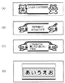
以上のようにしてユーザ作成パターンの外枠情報を揃った場合や、上述したステップS3でいずれかの装置用意パターンが指示された場合には、CPU21は、その外枠パターンとその外枠パターンで囲繞される文字列とを共に含む確認用の印刷イメージ画像(図7参照)を表示させ(S21)、ユーザが肯定したか否定したかを判別する(S22)。
When the outer frame information of the user-created pattern is prepared as described above, or when any device prepared pattern is instructed in step S3 described above, the
印刷イメージの表示処理は、ユーザ作成パターンの場合も、装置用意パターンに対して従来のテープ印刷装置が行っていた方法とほぼ同様である。すなわち、ユーザ作成パターンの前罫部分の図形を、装置用意パターンの前罫部分の図形と同様に見なし、かつ、ユーザ作成パターンの後罫部分の図形を、装置用意パターンの後罫部分の図形と同様に見なしてドット展開などを行う。前罫部分や後罫部分に記号を適用する場合であっても、ドット展開を行う元となるフォント情報は、入力文字列中に含める場合での記号のフォント情報と同一である。すなわち、同一記号に関し、前罫部分や後罫部分に適用する場合用のフォント情報と、入力文字列に含める場合用のフォント情報とを別個に設けている訳ではない。アウトラインフォントの場合には、同一のフォント情報で、上記2つの場合に対応できる。 The display processing of the print image is almost the same as that performed by the conventional tape printer for the device-prepared pattern for the user-created pattern. That is, the figure of the front ruled part of the user-created pattern is regarded in the same manner as the figure of the front ruled part of the device-prepared pattern, and the figure of the rear ruled part of the user-created pattern Dot expansion etc. is performed in the same way. Even when a symbol is applied to the front ruled part and the rear ruled part, the font information from which the dot expansion is performed is the same as the font information of the symbol when included in the input character string. That is, for the same symbol, font information for use in the front ruled portion and the rear ruled portion and font information for inclusion in the input character string are not separately provided. In the case of an outline font, the above two cases can be handled with the same font information.
なお、装置用意パターンに対する印刷イメージの表示処理と、ユーザ作成パターンに対する印刷イメージの表示処理とで異なる点は、ドット展開時に、図形の向きが逆向きに設定されている前罫部分及び又は後罫部分の図形は、左右反転してドット展開する点である。また、上罫及び下罫も、指示された線種にあうようにドット展開する点である。 The difference between the print image display process for the device-prepared pattern and the print image display process for the user-created pattern is that the front ruled part and / or the rear ruled pattern in which the orientation of the figure is set in the reverse direction at the time of dot development. The graphic of the part is a point where the dots are developed by flipping left and right. In addition, the upper rule and the lower rule are also dots that are developed so as to match the designated line type.
図7は、ユーザ作成パターンの印刷イメージ例を示す説明図である。なお、図7は、作成されたラベルを表すものと見ることもできる。図7(A)は、記号の中から、ねずみ図形の記号が前罫部分の図形として選択され、かつ、記号の中から、くま図形の記号が後罫部分の図形として選択された場合を示している。図7(B)及び(C)はそれぞれ、記号の中から、新幹線図形の記号が前罫部分及び後罫部分の図形として選択された場合を示しており、図7(B)は、前罫部分及び後罫部分共に、新幹線図形(の記号)がそのまま適用され、図7(C)は、後罫部分の新幹線図形が記号として用意されている向きの逆向きに指定された場合を示している。図7(D)は、線だけでなる外枠であるが、前罫及び後罫として破線が、上罫として細線が、下罫として太線が指定された場合を示している。 FIG. 7 is an explanatory diagram illustrating an example of a print image of a user created pattern. Note that FIG. 7 can also be viewed as representing the created label. FIG. 7A shows a case in which a mouse figure symbol is selected as a front ruled part graphic and a bear figure symbol is selected as a rear ruled figure from the symbols. ing. FIGS. 7B and 7C each show a case where the symbol of the Shinkansen figure is selected from the symbols as the figure of the front ruled part and the rear ruled part. FIG. The Shinkansen figure (symbol) is applied as it is to both the part and the rear ruled part, and FIG. 7C shows the case where the Shinkansen figure of the rear ruled part is designated in the opposite direction as the symbol. Yes. FIG. 7D shows an outer frame consisting only of lines, where a broken line is designated as the front rule and the rear rule, a fine line is designated as the upper rule, and a thick line is designated as the lower rule.
確認用の印刷イメージの表示に対し、ユーザがOKを指示すると、CPU21は、表示を、外枠や表組の付与処理を起動するキーが操作される直前の表示内容に戻したり、外枠情報を入力文字列に対する付随情報として記憶したりするなどの終了時処理を行い(S23)、外枠付与や表組付与の一連の処理を終了する。一方、確認用の印刷イメージの表示に対し、ユーザがNGを指示すると、CPU21は、上述したステップS2に戻って、外枠パターンの選択処理を最初からやり直すようにさせる。
When the user instructs OK for the display of the print image for confirmation, the
表組が選択された場合の処理も、上述した外枠が選択された場合の処理とほぼ同様である。異なる点は、ユーザ作成パターンの一連の処理の中に、行間罫の線種を選択させる処理も含まれる点である。 The processing when the table set is selected is almost the same as the processing when the above-described outer frame is selected. The difference is that the process of selecting the line type of the line rule is included in the series of processes of the user created pattern.
印刷指令時の処理は、印刷イメージの表示時の処理とほぼ同様である。印刷イメージの表示時の処理が、装填されているテープ幅に関係なく、所定のテープ幅が装填されていると見なした処理である場合であれば、印刷指令時の処理は、テープ幅に応じて、外枠などの前罫部分や後罫部分の図形大きさや、上罫や下罫の線幅を決定する点が異なっている。 The processing at the time of the print command is almost the same as the processing at the time of displaying the print image. If the processing at the time of displaying the print image is processing that assumes that the predetermined tape width is loaded regardless of the loaded tape width, the processing at the time of print command is the tape width. Accordingly, the figure size of the front ruled part and the rear ruled part such as the outer frame and the line width of the upper ruled line and the lower ruled line are different.
以上のように、上記実施形態によれば、ユーザによる外枠パターンや表組パターンの作成機能を設けたので、ユーザは、装置固定パターンから外枠パターンや表組パターンを選択できるだけでなく、装置固定パターンに所望するものがない場合には、所望する外枠パターンや表組パターンを作成することもできる。 As described above, according to the above-described embodiment, since the user has a function of creating an outer frame pattern and a table pattern, the user can not only select the outer frame pattern and the table pattern from the device fixed pattern, but also the device If there is no desired fixed pattern, a desired outer frame pattern or table pattern can be created.
ユーザが作成する外枠パターンや表組パターンでは、前罫部分や後罫部分の一方又は両方に図形や線を配置しないこともでき、また、任意の記号の図形を配置でき、線にする場合であっても線種を指定でき、さらに、上罫及び下罫の線種も指定できるので、作成可能な外枠パターンや表組パターンは非常に多種類になっている。 In the case of an outer frame pattern or table pattern created by the user, it is possible not to place a figure or line on one or both of the front ruled part and the rear ruled part, and it is possible to place a figure with any symbol and make it a line Even so, line types can be specified, and line types for upper and lower rules can also be specified, so that there are a great variety of outer frame patterns and table patterns that can be created.
また、入力文字列に含めることが可能な既に存在する記号情報(例えばアウトラインフォント情報でなる)を利用して、外枠パターンや表組パターンを作成させるので、外枠パターンや表組パターンの作成機能を設けても、作成機能のために新たに必要となるデータ量をごく抑えることができる。すなわち、機能追加に対して、ROMなどの記憶手段での必要記憶容量をごく抑えることができ、メモリ素子の増加を不要とし、装置を大型化させることがない。 Also, since the outer frame pattern and table pattern are created using the existing symbol information that can be included in the input character string (eg, outline font information), the outer frame pattern and table pattern are created. Even if the function is provided, the amount of data newly required for the creation function can be extremely reduced. That is, the required storage capacity of the storage means such as the ROM can be extremely suppressed with respect to the addition of functions, an increase in memory elements is unnecessary, and the apparatus is not enlarged.
(B)他の実施形態
上記実施形態の説明においても、種々変形実施形態を説明したが、さらに以下に例示するような変形実施形態を挙げることができる。
(B) Other Embodiments In the description of the above embodiment, various modified embodiments have been described. However, modified embodiments as exemplified below can be cited.
上記実施形態では、記号をメニュー表示から選択させるものを示したが、他の方法で記号を入力させる方法を適用しても良い。例えば、記号に対応するコード入力で記号を選択させるようにしても良い。 In the above embodiment, the symbol is selected from the menu display, but a method of inputting the symbol by another method may be applied. For example, a symbol may be selected by inputting a code corresponding to the symbol.
また、上記実施形態では、入力文字列中には含めることができる記号の種類を、第1階層の表示画像で選択させるものを示したが、入力文字列中には含めることができない図形(記号)の種類を設けるようにしても良い。すなわち、外枠パターンや表組パターンの前罫部分や後罫部分にだけ適用できる記号種類を設けるようにしても良い。例えば、各装置固定パターンでの前罫図形や後罫図形の全てを何らかの観点で分類し、分類した記号種類を設けるようにしても良い。逆に、各装置固定パターンでの前罫図形や後罫図形を、入力文字列中に含めることができる記号として扱うことができるようにしても良い。 In the above-described embodiment, the type of symbols that can be included in the input character string has been shown to be selected in the display image of the first hierarchy. However, the graphic (symbol that cannot be included in the input character string) ) Types may be provided. That is, a symbol type that can be applied only to the front ruled part and the rear ruled part of the outer frame pattern or the table pattern may be provided. For example, all the front ruled graphics and rear ruled graphics in each device fixed pattern may be classified from some viewpoint, and the classified symbol types may be provided. Conversely, the front ruled pattern and the rear ruled pattern in each device fixed pattern may be handled as symbols that can be included in the input character string.
さらに、上記実施形態では、前罫図形や後罫図形として、ユーザが任意指定できるものが記号であったが、記号以外をも指定可能とするようにしても良い。例えば、ひらがな、カタカナ、漢字、英数字などの一般的な文字も、前罫図形や後罫図形として指定可能としても良く、一般的な文字でも、前罫図形や後罫図形として指定可能なものを、文字に対応付けた外枠可能フラグなどにより限定するようにしても良い。その他、図形が登録されることが多い外字や、電子カメラやイメージスキャナで読み取ったイラストデータ等(例えば、パソコン及び周辺機器でなるテープ印刷システムの場合に好適である)も、前罫図形や後罫図形として指定可能にしても良い。図8は、一般的な文字を利用した外枠パターンの一例を示すものであり、「危」及び「険」はそれぞれ、前罫図形、後罫図形として指定されたものである。 Furthermore, in the above-described embodiment, symbols that can be arbitrarily designated by the user as the front ruled graphic and the rear ruled graphic are symbols, but other symbols may be designated. For example, general characters such as hiragana, katakana, kanji, and alphanumeric characters may be specified as front ruled shapes and back ruled shapes, and general characters can also be specified as front ruled shapes and rear ruled shapes. May be limited by an outer frame possible flag associated with a character. In addition, external characters that are often registered with graphics, illustration data read by an electronic camera or image scanner, etc. (for example, suitable for a tape printing system consisting of a personal computer and peripheral devices) are also included in It may be specified as a ruled figure. FIG. 8 shows an example of an outer frame pattern using general characters. “Danger” and “Steep” are designated as a front ruled graphic and a rear ruled graphic, respectively.
さらにまた、上記実施形態では、前罫部分の決定された記号(図形)により後罫部分の記号(図形)を装置が自動的に決定できるものを示したが、前罫部分の決定された記号(図形)により、後罫部分の記号(図形)、上罫及び下罫の線種を装置が自動的に決定できるようにしても良い。同様に、上罫の決定された線種により、下罫の線種を装置が自動的に決定できるようにしても良い。 Furthermore, in the above embodiment, the apparatus has been shown in which the symbol (graphic) of the rear ruled part can be automatically determined by the determined symbol (graphic) of the front ruled part. Depending on the (figure), the apparatus may automatically determine the symbol (figure) of the rear ruled part, the line type of the upper ruled line and the lower ruled line. Similarly, the apparatus may automatically determine the line type of the lower rule based on the line type determined for the upper rule.
上記実施形態では、前罫部分の決定された記号(図形)に応じ、選択できない後罫部分の記号を装置が予め定めておくものを示したが、前罫部分の決定された記号(図形)に応じ、選択できない後罫部分の記号、上罫及び下罫の線種を装置が予め定めておくようにしても良い。同様に、上罫の決定された線種に応じ、選択できない下罫の線種を装置が予め定めておくようにしても良い。 In the above-described embodiment, the apparatus predetermines the symbols of the rear ruled portion that cannot be selected in accordance with the symbols (graphics) determined for the front ruled portion. Accordingly, the apparatus may determine in advance the symbols of the rear ruled portion that cannot be selected and the line types of the upper and lower rules. Similarly, the apparatus may predetermine the line type of the lower rule that cannot be selected in accordance with the determined line type of the upper rule.
また、上記実施形態では、前罫部分及び後罫部分の記号の組み合わせに関係なく任意に向きを指定できるものを示したが、向きを指定できる組み合わせ条件を設けるようにしても良い。例えば、前罫部分及び後罫部分の記号が同一の場合にのみ、それぞれの記号の向きを指定できるようにしても良い。 In the above-described embodiment, the direction can be specified arbitrarily regardless of the combination of the symbols of the front ruled part and the rear ruled part. However, a combination condition for specifying the direction may be provided. For example, the direction of each symbol may be designated only when the symbols of the front ruled part and the rear ruled part are the same.
さらに、上記実施形態では、決定された前罫部分や後罫部分の記号に対して向きを指定できるものを示したが、他の修飾属性などを指定できるようにしても良い。例えば、前罫部分や後罫部分の記号に対して、白黒反転を指定できるようにしても良い。 Further, in the above-described embodiment, the direction that can be specified for the symbols of the determined front ruled part and rear ruled part has been shown. However, other modification attributes may be specified. For example, black and white inversion may be designated for the symbols of the front ruled part and the rear ruled part.
さらにまた、上記実施形態では、前罫部分及び後罫部分について、要素として不存在を指示できるものを示したが、上罫及び又は下罫についても不存在を指示できるようにしても良い。但し、全ての要素の不存在を拒否するようにしても良い。 Furthermore, in the above-described embodiment, the presence of the front ruled part and the rear ruled part that can be instructed as non-existing elements has been shown. However, the absence of all elements may be rejected.
上記実施形態では、外枠要素として指定された記号も、入力文字列の要素として指定された場合と同様に、フォントとして用意されているものに対し縦横共に同じ倍率でドット展開するものを示したが、外枠要素として指定された場合には、縦方向及び横方向でドット展開時の倍率を変えるようにしても良い。例えば、縦方向及び横方向の倍率比を5:4でドット展開するようにしても良い。 In the above embodiment, the symbol designated as the outer frame element is also displayed as a font that is dot-expanded at the same magnification both vertically and horizontally as in the case where it is designated as an element of the input character string. However, when designated as an outer frame element, the magnification at the time of dot development may be changed in the vertical direction and the horizontal direction. For example, the dots may be developed with a vertical and horizontal magnification ratio of 5: 4.
上記実施形態の説明では、横書きでの外枠付与処理を中心に説明したが、縦書きでの外枠付与処理についても同様なことは勿論である。特許請求の範囲における「前罫」、「後罫」、「上罫」、「下罫」の用語はそれぞれ、縦書きでの「上罫」、「下罫」、「右罫」、「左罫」をも含む概念とする。 In the description of the above embodiment, the outer frame providing process in horizontal writing has been mainly described, but the same applies to the outer frame applying process in vertical writing. The terms “front rule”, “back rule”, “upper rule”, and “lower rule” in the claims are “upper rule”, “lower rule”, “right rule”, and “left” in vertical writing, respectively. The concept includes “ruled lines”.
上記実施形態では、専用機としてのテープ印刷装置を示したが、パソコンとラベルプリンタとが結合されたテープ印刷システムに、本発明の技術思想を適用するようにしても良く、また、専用機としてのスタンプ(印章)作成装置や、パソコンとスタンプ作成用周辺装置とが結合されたスタンプ作成システムなどに、本発明の技術思想を適用するようにしても良い。例えば、パソコンとラベルプリンタとが結合されたテープ印刷システムであれば、外枠・表組付与プログラム22aや印刷処理用プログラム22bを含むラベル作成用プログラム(アプリケーションプログラム)を記録した記録媒体から、パソコンにそのプログラムがインストールされて利用されることになる。専用機としてのスタンプ(印章)作成装置や、パソコンとスタンプ作成用周辺装置とが結合されたスタンプ作成システムでは、外枠機能のみではある(表組機能はない)が、その外枠機能に本発明の技術思想を適用することができる。
In the above embodiment, the tape printer as a dedicated machine is shown. However, the technical idea of the present invention may be applied to a tape printing system in which a personal computer and a label printer are combined. The technical idea of the present invention may be applied to a stamp (stamp) creating apparatus or a stamp creating system in which a personal computer and a stamp creating peripheral device are combined. For example, in the case of a tape printing system in which a personal computer and a label printer are combined, a personal computer can be used from a recording medium on which a label creation program (application program) including an outer frame / table
10…入力部、11…キー入力部、11a…言語変換キー、11b…言語併記キー、20…制御部、21…CPU、22…ROM、22a…外枠・表組付与プログラム、22b…印刷処理用プログラム、30…出力部、32…サーマルヘッド、35…液晶ディスプレイ。
DESCRIPTION OF
Claims (13)
少なくとも上記前罫要素及び又は上記後罫要素として、上記入力文字列の文字要素として入力し得るものから任意の1文字を指定させる枠要素任意指定手段と、
印刷指令時に、上記枠要素任意指定手段によって任意指定された文字要素を、上記前罫要素及び又は上記後罫要素としてドット展開する任意枠要素展開手段と
を有することを特徴とする小印刷物作成装置。 In an input character string of about several lines, in a small printed matter creation device having a function of giving a frame shape including elements of at least a front rule, a back rule, an upper rule, and a lower rule,
Frame element arbitrary designation means for designating any one character from those that can be input as a character element of the input character string as at least the front rule element and / or the rear rule element;
A small printed matter creating apparatus comprising: an arbitrary frame element expanding unit that expands a character element arbitrarily specified by the frame element arbitrary specifying unit at the time of printing as the front ruled element and / or the rear ruled element. .
上記任意枠要素展開手段は、上記枠要素任意指定手段によって任意指定された線種に応じ、上記上罫要素及び又は上記下罫要素の部分に関するドット展開を行う
ことを特徴とする請求項1〜4のいずれかに記載の小印刷物作成装置。 The frame element arbitrary designation means can designate the line type of the upper ruled element and / or the lower ruled element,
The said arbitrary frame element expansion | deployment means performs the dot expansion | deployment regarding the part of the said upper ruled element and / or the said lower ruled element according to the line type arbitrarily designated by the said frame element arbitrary designation | designated means. 4. The small printed matter creating apparatus according to any one of 4 above.
少なくとも上記前罫要素及び又は上記後罫要素として、上記入力文字列の文字要素として入力し得るものから任意の1文字を指定させる枠要素任意指定工程と、
印刷指令時に、上記枠要素任意指定工程によって任意指定された文字要素を、上記前罫要素及び又は上記後罫要素としてドット展開する任意枠要素展開工程と
を含むことを特徴とする小印刷物作成方法。 In an input character string of about several lines, in a small printed matter creation method having a function of giving a frame shape including elements of at least a front rule, a rear rule, an upper rule, and a lower rule,
A frame element optional designating step for designating any one character from those that can be input as a character element of the input character string as at least the front ruled element and / or the rear ruled element;
A small printed matter creating method comprising: an optional frame element expanding step of expanding a character element arbitrarily specified in the frame element optional specifying step at the time of printing as the front ruled element and / or the rear ruled element. .
上記任意枠要素展開工程は、上記枠要素任意指定工程によって任意指定された線種に応じ、上記上罫要素及び又は上記下罫要素の部分に関するドット展開を行う
ことを特徴とする請求項7〜10のいずれかに記載の小印刷物作成方法。 In the frame element arbitrary designation step, the line type of the upper ruled element and / or the lower ruled element can be designated,
The arbitrary frame element expanding step performs dot expansion related to the upper ruled element and / or the lower ruled element portion according to the line type arbitrarily specified in the frame element optional specifying step. The method for producing a small printed material according to any one of 10.
13. A small printed matter creating program characterized in that each step of the small printed matter creating method according to claim 7 is described by a code executable by a computer.
Priority Applications (5)
| Application Number | Priority Date | Filing Date | Title |
|---|---|---|---|
| JP2003340290A JP2005103929A (en) | 2003-09-30 | 2003-09-30 | Apparatus for forming small printed matter, method for forming small printed matter and program for forming small printed matter |
| US10/942,101 US7033092B2 (en) | 2003-09-30 | 2004-09-16 | Apparatus, method and program for producing small prints |
| KR1020040077322A KR100628800B1 (en) | 2003-09-30 | 2004-09-24 | Apparatus, method and program recorded medium for producing small prints |
| TW093129454A TWI249702B (en) | 2003-09-30 | 2004-09-29 | Apparatus, method and program for producing small prints |
| CNB2004100855788A CN100421961C (en) | 2003-09-30 | 2004-09-30 | Device, method and program for manufacturing small print |
Applications Claiming Priority (1)
| Application Number | Priority Date | Filing Date | Title |
|---|---|---|---|
| JP2003340290A JP2005103929A (en) | 2003-09-30 | 2003-09-30 | Apparatus for forming small printed matter, method for forming small printed matter and program for forming small printed matter |
Publications (2)
| Publication Number | Publication Date |
|---|---|
| JP2005103929A true JP2005103929A (en) | 2005-04-21 |
| JP2005103929A5 JP2005103929A5 (en) | 2006-08-10 |
Family
ID=34509671
Family Applications (1)
| Application Number | Title | Priority Date | Filing Date |
|---|---|---|---|
| JP2003340290A Pending JP2005103929A (en) | 2003-09-30 | 2003-09-30 | Apparatus for forming small printed matter, method for forming small printed matter and program for forming small printed matter |
Country Status (5)
| Country | Link |
|---|---|
| US (1) | US7033092B2 (en) |
| JP (1) | JP2005103929A (en) |
| KR (1) | KR100628800B1 (en) |
| CN (1) | CN100421961C (en) |
| TW (1) | TWI249702B (en) |
Cited By (3)
| Publication number | Priority date | Publication date | Assignee | Title |
|---|---|---|---|---|
| JP2015208891A (en) * | 2014-04-24 | 2015-11-24 | ブラザー工業株式会社 | Printing label creation device |
| JP2016060145A (en) * | 2014-09-19 | 2016-04-25 | カシオ計算機株式会社 | Printer, printing method and program |
| JP2017007153A (en) * | 2015-06-18 | 2017-01-12 | ブラザー工業株式会社 | Lettering apparatus |
Families Citing this family (4)
| Publication number | Priority date | Publication date | Assignee | Title |
|---|---|---|---|---|
| WO2008031134A1 (en) * | 2006-09-11 | 2008-03-20 | Silverbrook Research Pty Ltd | Digital photo frame with integral printer |
| JP5299011B2 (en) * | 2009-03-25 | 2013-09-25 | セイコーエプソン株式会社 | Tape printer, control method and program for tape printer |
| JP5885122B2 (en) * | 2012-03-19 | 2016-03-15 | ブラザー工業株式会社 | Print label production device |
| JP7070741B1 (en) * | 2021-03-01 | 2022-05-18 | カシオ計算機株式会社 | Print control device, print control method, and print control program |
Family Cites Families (7)
| Publication number | Priority date | Publication date | Assignee | Title |
|---|---|---|---|---|
| JP2864412B2 (en) | 1993-05-18 | 1999-03-03 | カシオ計算機株式会社 | Printing equipment |
| JPH07314802A (en) | 1994-05-30 | 1995-12-05 | Casio Comput Co Ltd | Printer |
| US5816392A (en) * | 1994-10-20 | 1998-10-06 | Fuji Photo Film Co., Ltd. | Photographic film and print organizer |
| US5828442A (en) * | 1996-02-27 | 1998-10-27 | Eastman Kodak Company | Index print attachable to an image recording medium |
| CN1245940A (en) * | 1998-08-21 | 2000-03-01 | 文鼎科技开发股份有限公司 | Structural graphic display system |
| US20020114627A1 (en) * | 1998-10-21 | 2002-08-22 | Truc James A. | CD index print label |
| US6419781B2 (en) * | 1998-10-21 | 2002-07-16 | Eastman Kodak Company | Index sticker print |
-
2003
- 2003-09-30 JP JP2003340290A patent/JP2005103929A/en active Pending
-
2004
- 2004-09-16 US US10/942,101 patent/US7033092B2/en active Active
- 2004-09-24 KR KR1020040077322A patent/KR100628800B1/en not_active IP Right Cessation
- 2004-09-29 TW TW093129454A patent/TWI249702B/en not_active IP Right Cessation
- 2004-09-30 CN CNB2004100855788A patent/CN100421961C/en not_active Expired - Fee Related
Cited By (3)
| Publication number | Priority date | Publication date | Assignee | Title |
|---|---|---|---|---|
| JP2015208891A (en) * | 2014-04-24 | 2015-11-24 | ブラザー工業株式会社 | Printing label creation device |
| JP2016060145A (en) * | 2014-09-19 | 2016-04-25 | カシオ計算機株式会社 | Printer, printing method and program |
| JP2017007153A (en) * | 2015-06-18 | 2017-01-12 | ブラザー工業株式会社 | Lettering apparatus |
Also Published As
| Publication number | Publication date |
|---|---|
| KR20050031973A (en) | 2005-04-06 |
| CN1603127A (en) | 2005-04-06 |
| TW200515269A (en) | 2005-05-01 |
| KR100628800B1 (en) | 2006-09-26 |
| CN100421961C (en) | 2008-10-01 |
| US20050086580A1 (en) | 2005-04-21 |
| US7033092B2 (en) | 2006-04-25 |
| TWI249702B (en) | 2006-02-21 |
Similar Documents
| Publication | Publication Date | Title |
|---|---|---|
| KR19980063578A (en) | Character printer | |
| JP2005103929A (en) | Apparatus for forming small printed matter, method for forming small printed matter and program for forming small printed matter | |
| JPH0473188B2 (en) | ||
| JPH03129397A (en) | Document processor | |
| JP2008162236A (en) | Tape printing system | |
| JP2864412B2 (en) | Printing equipment | |
| EP0573262B1 (en) | Wordprocessing device | |
| JP4491220B2 (en) | Small printed matter creating apparatus, small printed matter creating method, and small printed matter creating program | |
| JP3249687B2 (en) | Tape-shaped label making device | |
| EP0606768A2 (en) | Registration dot pattern data processor of a text processing apparatus | |
| JPH06143690A (en) | Tape printing apparatus | |
| JP2998829B2 (en) | Tape-shaped label making device | |
| JP3292393B2 (en) | Document processing device | |
| JP2815158B2 (en) | Character processor | |
| JP3095046B2 (en) | Dot pattern data creation device for registration of tape printer | |
| JPH07276715A (en) | Tape printer capable of printing a plurality of blocks in optional number of lines | |
| TW200532566A (en) | System, method, and program for generating barcode data | |
| JP3390534B2 (en) | Tape printer | |
| JPH0752496A (en) | Printer | |
| JPH07125373A (en) | Printing device | |
| JP2560650B2 (en) | Tape printer | |
| JP2606126B2 (en) | Tape recorder | |
| JPH0679927A (en) | Scale printer | |
| JPH04118769A (en) | Document preparing device | |
| JPH06203028A (en) | Document processor |
Legal Events
| Date | Code | Title | Description |
|---|---|---|---|
| A521 | Request for written amendment filed |
Free format text: JAPANESE INTERMEDIATE CODE: A523 Effective date: 20060621 |
|
| A621 | Written request for application examination |
Free format text: JAPANESE INTERMEDIATE CODE: A621 Effective date: 20060621 |
|
| A131 | Notification of reasons for refusal |
Free format text: JAPANESE INTERMEDIATE CODE: A131 Effective date: 20090728 |
|
| A521 | Request for written amendment filed |
Free format text: JAPANESE INTERMEDIATE CODE: A523 Effective date: 20090928 |
|
| A02 | Decision of refusal |
Free format text: JAPANESE INTERMEDIATE CODE: A02 Effective date: 20100105 |