JP2005091815A - Radiation image reader - Google Patents
Radiation image reader Download PDFInfo
- Publication number
- JP2005091815A JP2005091815A JP2003325690A JP2003325690A JP2005091815A JP 2005091815 A JP2005091815 A JP 2005091815A JP 2003325690 A JP2003325690 A JP 2003325690A JP 2003325690 A JP2003325690 A JP 2003325690A JP 2005091815 A JP2005091815 A JP 2005091815A
- Authority
- JP
- Japan
- Prior art keywords
- scanning
- afterglow
- light
- correction
- light emission
- Prior art date
- Legal status (The legal status is an assumption and is not a legal conclusion. Google has not performed a legal analysis and makes no representation as to the accuracy of the status listed.)
- Pending
Links
- 230000005855 radiation Effects 0.000 title claims abstract description 49
- 229920006395 saturated elastomer Polymers 0.000 claims abstract description 26
- 238000001514 detection method Methods 0.000 claims description 55
- 230000005284 excitation Effects 0.000 claims description 50
- OAICVXFJPJFONN-UHFFFAOYSA-N Phosphorus Chemical compound [P] OAICVXFJPJFONN-UHFFFAOYSA-N 0.000 claims description 36
- 238000004020 luminiscence type Methods 0.000 claims description 34
- 238000011084 recovery Methods 0.000 claims description 16
- 230000009467 reduction Effects 0.000 claims description 10
- 230000006866 deterioration Effects 0.000 abstract description 5
- 238000006243 chemical reaction Methods 0.000 description 36
- 238000010586 diagram Methods 0.000 description 15
- 238000004364 calculation method Methods 0.000 description 12
- 238000013139 quantization Methods 0.000 description 12
- 230000014509 gene expression Effects 0.000 description 10
- 230000006870 function Effects 0.000 description 8
- 238000003384 imaging method Methods 0.000 description 7
- 238000003745 diagnosis Methods 0.000 description 6
- 230000002093 peripheral effect Effects 0.000 description 6
- 238000000034 method Methods 0.000 description 4
- 238000005070 sampling Methods 0.000 description 3
- 230000002411 adverse Effects 0.000 description 2
- 230000005540 biological transmission Effects 0.000 description 2
- 230000000694 effects Effects 0.000 description 2
- 239000000284 extract Substances 0.000 description 2
- 238000005424 photoluminescence Methods 0.000 description 2
- 239000004065 semiconductor Substances 0.000 description 2
- GGCZERPQGJTIQP-UHFFFAOYSA-N sodium;9,10-dioxoanthracene-2-sulfonic acid Chemical compound [Na+].C1=CC=C2C(=O)C3=CC(S(=O)(=O)O)=CC=C3C(=O)C2=C1 GGCZERPQGJTIQP-UHFFFAOYSA-N 0.000 description 2
- 230000002238 attenuated effect Effects 0.000 description 1
- 230000037237 body shape Effects 0.000 description 1
- 230000008859 change Effects 0.000 description 1
- 230000007423 decrease Effects 0.000 description 1
- 230000003247 decreasing effect Effects 0.000 description 1
- 230000002542 deteriorative effect Effects 0.000 description 1
- 201000010099 disease Diseases 0.000 description 1
- 208000037265 diseases, disorders, signs and symptoms Diseases 0.000 description 1
- 239000000463 material Substances 0.000 description 1
- 230000003287 optical effect Effects 0.000 description 1
- 239000013307 optical fiber Substances 0.000 description 1
- 230000008569 process Effects 0.000 description 1
- 230000004044 response Effects 0.000 description 1
- 238000007789 sealing Methods 0.000 description 1
- 230000035945 sensitivity Effects 0.000 description 1
- 230000001360 synchronised effect Effects 0.000 description 1
Images


Abstract
Description
この発明は、放射線画像情報が蓄積される輝尽性蛍光体プレートの輝尽発光から、残光成分を除去し、正確な輝尽発光情報を取得する放射線画像読取装置に関する。 The present invention relates to a radiographic image reading apparatus that removes afterglow components from the photostimulated luminescence of a photostimulable phosphor plate in which radiographic image information is stored, and acquires accurate photostimulated luminescence information.
被写体を透過したX線を蛍光スクリーン(蛍光体層)に照射し、この透過線量に比例した可視光を生じさせ、この可視光を市販の銀塩写真と同様のフィルムに露光し現像する、いわゆる放射線写真が、病気診断の際の放射線画像として多く用いられている。 A so-called X-ray transmitted through a subject is irradiated onto a fluorescent screen (phosphor layer) to generate visible light proportional to the transmitted dose, and this visible light is exposed to a film similar to a commercially available silver salt photograph and developed. Radiographs are often used as radiographic images for disease diagnosis.
しかし、近年、銀塩写真を用いることなく、蛍光体層から直接、被写体の画像情報を読み取ることが行われる。これによれば、被写体を透過したX線を、輝尽性蛍光体に吸収せしめ、その後、この輝尽性蛍光体を励起光で励起し、この輝尽性蛍光体に吸収および蓄積されたX線エネルギーおよび画像情報を、蛍光として輝尽発光させ、さらにこの輝尽発光を光検出手段により光電変換して、画像情報の取得が行われる。 However, in recent years, image information of a subject is read directly from a phosphor layer without using a silver salt photograph. According to this, the X-ray transmitted through the subject is absorbed by the stimulable phosphor, and then the stimulable phosphor is excited by the excitation light, and the X-ray absorbed and accumulated in the stimulable phosphor. The line energy and the image information are stimulated to emit light as fluorescence, and this stimulated emission is photoelectrically converted by the light detection means to acquire image information.
ところで、輝尽性蛍光体は、励起光により輝尽発光を行うが、この輝尽発光は、励起光の照射終了後も、いわゆる残光として、輝尽性蛍光体に固有の応答時間の間、発光を続ける。従って、プレート状の輝尽性蛍光体プレートを、励起光で走査し、励起光により励起された輝尽発光を光電的に順次読み取り、画素単位の画像情報を取得する際に、励起光が照射される走査点からの輝尽発光のみでなく、励起光の照射が終了した走査点からの残光成分も含めて、励起光が照射される走査点に位置する画素の画像情報として蓄積される。これにより、走査点ごとの画像情報の分離が完全になされず、コントラスト分解能の低下、あるいは、表示される画像情報の鮮鋭度の低下等が生じる。 By the way, the photostimulable phosphor emits photostimulated light by excitation light, and this stimulated light emission remains as a so-called afterglow during the response time inherent to the photostimulable phosphor after the end of the excitation light irradiation. Continue to emit light. Therefore, when the plate-like photostimulable phosphor plate is scanned with excitation light, the excitation light is sequentially emitted to sequentially read the excitation light emitted by the excitation light and acquire image information in units of pixels. In addition to the stimulated light emission from the scanning point, the afterglow component from the scanning point where the irradiation of the excitation light is completed is stored as image information of the pixel located at the scanning point where the excitation light is irradiated. . As a result, the image information is not completely separated for each scanning point, and the contrast resolution is lowered or the sharpness of the displayed image information is lowered.
そこで、取得された画像情報に対して、経験的あるいは理論的に求められた残光情報に基づいて補正を行い、残光成分を除去することが行われる(例えば、特許文献1および2参照)。
しかしながら、上記背景技術によれば、被写体が肥満している際に、残光の補正が正しく行われない。すなわち、肥満した被写体においては、照射されるX線の被写体内における減弱が大きく、同一線量の線源を用いる場合には、輝尽性蛍光体プレートに到達するX線線量が減少する。一方、蛍光体層の粒状性は、到達するX線線量の減少に伴い、悪化することが知られている。 However, according to the background art, afterglow correction is not performed correctly when the subject is obese. That is, in an obese subject, the amount of X-rays irradiated is greatly attenuated in the subject, and the X-ray dose reaching the photostimulable phosphor plate is reduced when the same dose of radiation source is used. On the other hand, it is known that the granularity of the phosphor layer deteriorates as the X-ray dose that arrives decreases.
これらのことから、肥満した被写体においては、照射されるX線線量を、通常と比較して大きなものとし、蛍光体層の粒状性が悪化することを防止している。他方、X線照射線量の増大に伴い、光検出手段で扱われる光信号の最大値および最小値の比であるダイナミックレンジも大きなものが要求される。しかし、従来の光検出手段を用いる際には、このダイナミックレンジを越える光量が生じる際に、光検出手段の出力に飽和現象が起こる。 For these reasons, in obese subjects, the irradiated X-ray dose is set to be larger than usual to prevent the granularity of the phosphor layer from deteriorating. On the other hand, as the X-ray irradiation dose increases, a large dynamic range, which is a ratio between the maximum value and the minimum value of the optical signal handled by the light detection means, is required. However, when using the conventional light detection means, a saturation phenomenon occurs in the output of the light detection means when a light amount exceeding the dynamic range is generated.
この飽和現象が生じる場合には、光検出手段の出力は、輝尽発光の光量を正確に反映せず、ひいては、残光の補正を行う場合にも、正確な補正を行うことができない。 When this saturation phenomenon occurs, the output of the light detection means does not accurately reflect the light quantity of the stimulated light emission, and therefore, even when the afterglow is corrected, it cannot be corrected accurately.
これらのことから、肥満した被写体を撮影する際に、残光補正で生じるアーティファクト等の画質劣化を防止する放射線画像読取装置をいかに実現するかが重要となる。 For these reasons, when photographing an obese subject, it is important how to realize a radiation image reading apparatus that prevents image quality deterioration such as artifacts caused by afterglow correction.
この発明は、上述した従来技術による課題を解決するためになされたものであり、肥満した被写体を撮影する際に、残光補正で生じるアーティファクト等の画質劣化を防止する放射線画像読取装置を提供することを目的とする。 The present invention has been made to solve the above-described problems of the prior art, and provides a radiographic image reading apparatus that prevents image quality deterioration such as artifacts caused by afterglow correction when an obese subject is photographed. For the purpose.
上述した課題を解決し、目的を達成するために、請求項1に記載の発明にかかる放射線画像読取装置は、放射線画像情報が蓄積された輝尽性蛍光体プレートを、励起光で走査する走査手段と、前記走査を構成する走査点ごとに、前記励起光により生じる輝尽発光を検出する、4.3桁以上のダイナミックレンジを有する光検出手段と、前記検出された輝尽発光情報から、前記輝尽発光が生じる走査点と異なる走査点からの残光を除去し補正する残光補正手段と、を備えることを特徴とする。 In order to solve the above-described problems and achieve the object, the radiation image reading apparatus according to the first aspect of the present invention is a scanning that scans the stimulable phosphor plate in which the radiation image information is stored with excitation light. From the means, the photodetection means having a dynamic range of 4.3 digits or more for detecting the stimulated light emission caused by the excitation light for each scanning point constituting the scan, and the detected light emission information, And an afterglow correcting unit that removes and corrects afterglow from a scanning point different from the scanning point where the stimulated light emission occurs.
この請求項1に記載の発明では、走査手段により、放射線画像情報が蓄積された輝尽性蛍光体プレートを、励起光で走査し、4.3桁以上のダイナミックレンジを有する光検出手段により、走査を構成する走査点ごとに、励起光により生じる輝尽発光を検出し、残光補正手段により、検出された輝尽発光情報から、輝尽発光が生じる走査点と異なる走査点からの残光を除去し補正することとしているので、肥満した被写体を撮影する際にも、光検出手段が飽和することがなく、残光の補正を正確に行う。 In the first aspect of the present invention, the stimulable phosphor plate in which the radiation image information is stored is scanned with the excitation light by the scanning means, and the light detecting means having a dynamic range of 4.3 digits or more is used. For each scanning point constituting the scan, the photostimulated luminescence generated by the excitation light is detected, and the afterglow from the scanning point different from the scanning point where the photostimulated luminescence is generated from the detected photostimulated luminescence information by the afterglow correcting means. Therefore, even when an obese subject is photographed, the light detection means does not saturate, and the afterglow is corrected accurately.
また、請求項2に記載の発明にかかる放射線画像読取装置は、放射線画像情報が蓄積された輝尽性蛍光体プレートを、励起光で走査する走査手段と、前記走査を構成する走査点ごとに、前記励起光により生じる輝尽発光を検出する光検出手段と、前記検出された輝尽発光情報から、前記輝尽発光が生じる走査点と異なる走査点からの残光を除去し補正する残光補正手段と、を備える放射線画像読取装置であって、前記残光補正手段は、前記補正を行いつつ、前記走査点ごとに、前記光検出手段が飽和しているかどうかを判定し、前記飽和が生じた際には、前記補正を中止し、前記飽和が生じない際には、前記補正を続行する飽和逐次判定手段を備えることを特徴とする。 According to a second aspect of the present invention, there is provided a radiographic image reading apparatus comprising: scanning means for scanning a stimulable phosphor plate in which radiographic image information is stored with excitation light; and each scanning point constituting the scan. A photodetection means for detecting the photostimulated luminescence generated by the excitation light, and an afterglow for removing and correcting afterglow from a scanning point different from the scanning point at which the photostimulated luminescence occurs from the detected photostimulated luminescence information A radiological image reading apparatus comprising: a correction unit, wherein the afterglow correction unit determines whether the light detection unit is saturated for each scanning point while performing the correction, and the saturation is A saturation sequential determination means is provided for stopping the correction when it occurs, and continuing the correction when the saturation does not occur.
この請求項2に記載の発明では、残光補正手段は、飽和逐次判定手段により、補正を行いつつ、走査点ごとに、光検出手段が飽和しているかどうかを判定し、この飽和が生じた際には、補正を中止し、この飽和が生じない際には、補正を続行することとしているので、輝尽発光情報が飽和している走査点が存在する際の間違った残光補正を防止し、ひいては読み取り画像をアーティファクトの少ない高品質なものとする。 In the second aspect of the invention, the afterglow correcting means determines whether or not the light detecting means is saturated for each scanning point while performing correction by the saturation sequential determining means, and this saturation has occurred. In this case, the correction is stopped, and when this saturation does not occur, the correction is continued, so that erroneous afterglow correction is prevented when there is a scanning point where the photostimulated light emission information is saturated. As a result, the read image has a high quality with few artifacts.
また、請求項3に記載の発明にかかる放射線画像読取装置は、放射線画像情報が蓄積された輝尽性蛍光体プレートを、励起光で走査する走査手段と、前記走査を構成する走査点ごとに、前記励起光により生じる輝尽発光を検出する光検出手段と、前記検出された輝尽発光情報から、前記輝尽発光が生じる走査点と異なる走査点からの残光を除去し補正する残光補正手段と、を備える放射線画像読取装置であって、前記残光補正手段は、前記補正を行う前に、すべての前記走査点において、前記光検出手段が飽和しているかどうかを一括判定し、前記一括判定に基づいて、前記飽和が生じている際には、前記補正を中止し、前記飽和が生じていない際には、前記補正を行う飽和一括判定手段を備えることを特徴とする。 According to a third aspect of the present invention, there is provided a radiographic image reading apparatus comprising: a scanning unit that scans a stimulable phosphor plate in which radiographic image information is stored with excitation light; and a scanning point that constitutes the scanning. A photodetection means for detecting the photostimulated luminescence generated by the excitation light, and an afterglow for removing and correcting afterglow from a scanning point different from the scanning point at which the photostimulated luminescence occurs from the detected photostimulated luminescence information A correction unit, and the afterglow correction unit collectively determines whether the light detection unit is saturated at all the scanning points before performing the correction, Based on the collective determination, a saturation collective determination unit is provided that stops the correction when the saturation occurs and performs the correction when the saturation does not occur.
この請求項3に記載の発明では、残光補正手段は、飽和一括判定手段により、補正を行う前に、すべての走査点において、光検出手段が飽和しているかどうかを一括判定し、この一括判定に基づいて、飽和が生じている際には、補正を中止し、この飽和が生じていない際には、補正を行うこととしているので、輝尽発光情報が飽和している走査点が存在する際の間違った残光補正を防止し、ひいては読み取り画像をアーティファクトの少ない高品質なものとする。 In the invention according to the third aspect, the afterglow correcting means collectively determines whether or not the light detecting means is saturated at all scanning points before performing the correction by the saturation batch determining means. Based on the judgment, when the saturation occurs, the correction is stopped, and when the saturation does not occur, the correction is performed. Therefore, there is a scanning point where the photostimulated light emission information is saturated. This prevents erroneous afterglow correction when the image is read, and as a result, the read image has a high quality with few artifacts.
また、請求項4に記載の発明にかかる放射線画像読取装置は、放射線画像情報が蓄積された輝尽性蛍光体プレートを、励起光で走査する走査手段と、前記走査を構成する走査点ごとに、前記励起光により生じる輝尽発光を検出する光検出手段と、前記検出された輝尽発光情報から、前記輝尽発光が生じた走査点と異なる走査点からの残光を除去し補正する残光補正手段と、前記補正された輝尽発光情報のビット数を削減するビット削減手段と、を備えることを特徴とする。 According to a fourth aspect of the present invention, there is provided a radiographic image reading apparatus comprising: scanning means for scanning a stimulable phosphor plate in which radiographic image information is stored with excitation light; and each scanning point constituting the scan. A light detecting means for detecting the stimulated light emission caused by the excitation light, and a residual light for removing and correcting afterglow from a scanning point different from the scanning point where the stimulated light emission has occurred, from the detected stimulated light emission information. It comprises light correction means and bit reduction means for reducing the number of bits of the corrected stimulated light emission information.
この請求項4に記載の発明では、走査手段により、放射線画像情報が蓄積された輝尽性蛍光体プレートを、励起光で走査し、光検出手段により、走査を構成する走査点ごとに、励起光により生じる輝尽発光を検出し、残光補正手段により、検出された輝尽発光情報から、輝尽発光が生じた走査点と異なる走査点からの残光を除去し補正し、ビット削減手段により、補正された輝尽発光情報のビット数を削減することとしているので、肥満した被写体の撮像を行う場合にも、従来から用いられているダイナミックレンジ4.0桁の画像処理装置あるいは画像再生装置等を使用する。 In this invention, the stimulable phosphor plate in which the radiation image information is accumulated is scanned with excitation light by the scanning means, and excitation is performed for each scanning point constituting the scan by the light detection means. Detects the photostimulated luminescence caused by the light, and corrects the afterglow correcting means by removing and correcting the afterglow from the scanning point different from the scanning point where the photostimulated luminescence is generated from the detected photostimulated luminescence information. Therefore, the number of bits of the corrected stimulated light emission information is reduced, so that even when an obese subject is imaged, a conventionally used dynamic range 4.0 digit image processing apparatus or image reproduction is used. Use equipment.
また、請求項5に記載の発明にかかる放射線画像読取装置は、放射線画像情報が蓄積された輝尽性蛍光体プレートを、励起光で走査する走査手段と、前記走査を構成する走査点ごとに、前記励起光により生じる輝尽発光を検出する光検出手段と、前記光検出手段の非線形な読み取り特性に基づいて、前記輝尽発光情報の線形性を回復する線形性回復手段と、前記検出された輝尽発光情報から、前記輝尽発光が生じた走査点と異なる走査点からの残光を除去し補正する残光補正手段と、を備えることを特徴とする。 According to a fifth aspect of the present invention, there is provided a radiographic image reading apparatus comprising: scanning means for scanning a stimulable phosphor plate in which radiographic image information is stored with excitation light; and each scanning point constituting the scan. A light detecting means for detecting the stimulated emission generated by the excitation light, a linearity recovery means for recovering the linearity of the stimulated emission information based on a non-linear reading characteristic of the light detecting means, and the detected And afterglow correcting means for removing and correcting afterglow from a scanning point different from the scanning point where the stimulated light emission has occurred.
この請求項5に記載の発明では、走査手段により、放射線画像情報が蓄積された輝尽性蛍光体プレートを、励起光で走査し、光検出手段により、この走査を構成する走査点ごとに、励起光により生じる輝尽発光を検出し、線形性回復手段により、光検出手段の非線形な読み取り特性に基づいて、輝尽発光情報の線形性を回復し、残光補正手段により、検出された輝尽発光情報から、この輝尽発光が生じた走査点と異なる走査点からの残光を除去し補正することとしているので、肥満した被写体で、輝尽発光情報が、光検出手段の非線形特性を有する範囲にあっても、輝尽発光情報を線形化して正確な残光補正を行う。
In the invention according to
また、請求項6に記載の発明にかかる放射線画像読取装置は、放射線画像情報が蓄積された輝尽性蛍光体プレートを、励起光で走査する走査手段と、前記走査を構成する走査点ごとに、前記励起光により生じる輝尽発光を検出する光検出手段と、前記検出された輝尽発光情報から、前記輝尽発光が生じた走査点と異なる走査点からの残光を除去し補正する残光補正手段と、を備える放射線画像読取装置であって、前記残光補正手段は、前記光検出手段の非線形な読み取り特性に基づいて、前記輝尽発光情報を線形性を回復する線形性回復手段を備えることを特徴とする。 According to a sixth aspect of the present invention, there is provided a radiographic image reading apparatus comprising: scanning means for scanning a stimulable phosphor plate in which radiographic image information is stored with excitation light; and each scanning point constituting the scan. A light detecting means for detecting the stimulated light emission caused by the excitation light, and a residual light for removing and correcting afterglow from a scanning point different from the scanning point where the stimulated light emission has occurred, from the detected stimulated light emission information. A radiation image reading apparatus comprising: a light correction means, wherein the afterglow correction means recovers the linearity of the photostimulated luminescence information based on a nonlinear reading characteristic of the light detection means. It is characterized by providing.
この請求項6に記載の発明では、残光補正手段は、線形性回復手段により、光検出手段の非線形な読み取り特性に基づいて、輝尽発光情報を線形性を回復することとしているので、肥満した被写体で、輝尽発光情報が、光検出手段の非線形特性を有する範囲にあっても、輝尽発光情報を線形化して正確な残光補正を行う。 In the invention according to claim 6, the afterglow correcting means recovers the linearity of the photostimulated luminescence information based on the non-linear reading characteristic of the light detecting means by the linearity recovering means. Even if the photostimulated luminescence information is within the range having the non-linear characteristics of the light detection means, the photostimulated luminescence information is linearized and correct afterglow correction is performed.
以上説明したように、請求項1に記載の発明によれば、走査手段により、放射線画像情報が蓄積された輝尽性蛍光体プレートを、励起光で走査し、4.3桁以上のダイナミックレンジを有する光検出手段により、走査を構成する走査点ごとに、励起光により生じる輝尽発光を検出し、残光補正手段により、検出された輝尽発光情報から、輝尽発光が生じる走査点と異なる走査点からの残光を除去し補正することとしているので、肥満した被写体を撮影する際にも、光検出手段が飽和することがなく、残光の補正を正確に行うことができる。 As described above, according to the first aspect of the present invention, the stimulable phosphor plate in which the radiation image information is accumulated is scanned with the excitation light by the scanning means, and the dynamic range of 4.3 digits or more is obtained. The photodetection means that detects the stimulated light emission caused by the excitation light at each scanning point constituting the scan, and the afterglow correction means detects the stimulated light emission from the detected light emission information. Since afterglow from different scanning points is removed and corrected, even when an obese subject is photographed, the photodetection means is not saturated and the afterglow can be corrected accurately.
請求項2に記載の発明によれば、残光補正手段は、飽和逐次判定手段により、補正を行いつつ、走査点ごとに、光検出手段が飽和しているかどうかを判定し、この飽和が生じた際には、補正を中止し、この飽和が生じない際には、補正を続行することとしているので、輝尽発光情報が飽和している走査点が存在する際の間違った残光補正を防止し、ひいては読み取り画像をアーティファクトの少ない高品質なものとすることができる。 According to the second aspect of the present invention, the afterglow correcting means determines whether or not the light detecting means is saturated for each scanning point while performing correction by the saturation sequential determining means, and this saturation occurs. When this happens, the correction is stopped and the correction is continued when this saturation does not occur.Therefore, an incorrect afterglow correction is performed when there is a scanning point where the photostimulated light emission information is saturated. Therefore, the read image can be made high quality with few artifacts.
請求項3に記載の発明によれば、残光補正手段は、飽和一括判定手段により、補正を行う前に、すべての走査点において、光検出手段が飽和しているかどうかを一括判定し、この一括判定に基づいて、飽和が生じている際には、補正を中止し、この飽和が生じていない際には、補正を行うこととしているので、輝尽発光情報が飽和している走査点が存在する際の間違った残光補正を防止し、ひいては読み取り画像をアーティファクトの少ない高品質なものとすることができる。 According to the third aspect of the present invention, the afterglow correcting means collectively determines whether or not the light detecting means is saturated at all scanning points before performing the correction by the saturation batch determining means. Based on the collective determination, correction is stopped when saturation occurs, and correction is performed when saturation does not occur. It is possible to prevent erroneous afterglow correction when present, and thus to make the read image high quality with few artifacts.
請求項4に記載の発明によれば、走査手段により、放射線画像情報が蓄積された輝尽性蛍光体プレートを、励起光で走査し、光検出手段により、走査を構成する走査点ごとに、励起光により生じる輝尽発光を検出し、残光補正手段により、検出された輝尽発光情報から、輝尽発光が生じた走査点と異なる走査点からの残光を除去し補正し、ビット削減手段により、補正された輝尽発光情報のビット数を削減することとしているので、肥満した被写体の撮像を行う場合にも、従来から用いられているダイナミックレンジ4.0桁の画像処理装置あるいは画像再生装置等を使用することができる。
According to the invention described in
請求項5に記載の発明によれば、走査手段により、放射線画像情報が蓄積された輝尽性蛍光体プレートを、励起光で走査し、光検出手段により、この走査を構成する走査点ごとに、励起光により生じる輝尽発光を検出し、線形性回復手段により、光検出手段の非線形な読み取り特性に基づいて、輝尽発光情報の線形性を回復し、残光補正手段により、検出された輝尽発光情報から、この輝尽発光が生じた走査点と異なる走査点からの残光を除去し補正することとしているので、肥満した被写体で、輝尽発光情報が、光検出手段の非線形特性を有する範囲にあっても、輝尽発光情報を線形化して正確な残光補正を行うことができる。 According to the fifth aspect of the present invention, the stimulable phosphor plate in which the radiation image information is accumulated is scanned with the excitation light by the scanning means, and each scanning point constituting this scan is scanned by the light detecting means. The photoluminescence generated by the excitation light is detected, and the linearity recovery means recovers the linearity of the photoluminescence information based on the non-linear reading characteristics of the light detection means, and is detected by the afterglow correction means. Since the afterglow from the scanning point that is different from the scanning point where the stimulated light emission is removed is corrected from the stimulated light emission information, the stimulated light emission information is the non-linear characteristic of the light detection means in an obese subject. Even within the range having the light emission, it is possible to correct the afterglow correction by linearizing the photostimulated luminescence information.
請求項6に記載の発明によれば、残光補正手段は、線形性回復手段により、光検出手段の非線形な読み取り特性に基づいて、輝尽発光情報を線形性を回復することとしているので、肥満した被写体で、輝尽発光情報が、光検出手段の非線形特性を有する範囲にあっても、輝尽発光情報を線形化して正確な残光補正を行うことができる。 According to the sixth aspect of the present invention, the afterglow correcting means recovers the linearity of the photostimulated luminescence information based on the non-linear reading characteristic of the light detecting means by the linearity recovering means. Even in an obese subject, even if the photostimulated luminescence information is within a range having the nonlinear characteristics of the light detection means, the photostimulated luminescence information can be linearized and correct afterglow correction can be performed.
以下に添付図面を参照して、この発明にかかる放射線画像読取装置を実施するための最良の形態について説明する。なお、これにより本発明が限定されるものではない。
(実施の形態1)
まず、本実施の形態にかかる放射線画像読取装置(以下、読み取り装置と略称する)20を含む放射線撮像装置の全体構成について説明する。図1は、本発明にかかる、放射線撮像装置の全体構成を示す図である。放射線撮像装置は、放射線発生装置1、被写体2、輝尽性蛍光体プレート(以下、プレートと略称する)3、読み取り装置20、画像処理装置8および画像再生装置9を含む。また、読み取り装置20は、走査手段10、光検出手段4、対数変換回路5、A/D変換器6および残光補正手段7を含む。
The best mode for carrying out the radiation image reading apparatus according to the present invention will be described below with reference to the accompanying drawings. Note that the present invention is not limited thereby.
(Embodiment 1)
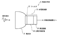
First, an overall configuration of a radiation imaging apparatus including a radiation image reading apparatus (hereinafter referred to as a reading apparatus) 20 according to the present embodiment will be described. FIG. 1 is a diagram showing an overall configuration of a radiation imaging apparatus according to the present invention. The radiation imaging apparatus includes a radiation generator 1, a subject 2, a stimulable phosphor plate (hereinafter abbreviated as a plate) 3, a reading device 20, an
放射線発生装置1は、X線を発生するX線管球等からなり、被写体2に対してX線を、爆射する。プレート3は、輝尽性蛍光体からなる平板状のプレートで、被写体2を透過したX線を吸収し、被写体2の透過画像情報を蓄積する。なお、プレート3は、用いる輝尽性蛍光体の材料として、例えば、特開昭61―72091号公報あるいは特開昭59―75200号公報に開示されているものを用い、また、プレートとしては、米国特許第4,769,549号明細書あるいは米国特許第5,023,461号明細書に開示されているものを用いる。 The radiation generation apparatus 1 includes an X-ray tube that generates X-rays, and bombards the subject 2 with X-rays. The plate 3 is a flat plate made of a photostimulable phosphor and absorbs X-rays transmitted through the subject 2 and accumulates transmission image information of the subject 2. The plate 3 uses, for example, those disclosed in JP-A-61-72091 or JP-A-59-75200 as the material of the stimulable phosphor to be used. Those disclosed in US Pat. No. 4,769,549 or US Pat. No. 5,023,461 are used.
走査手段10は、励起光をなす半導体レーザ光を、プレート3上に照射する。この照射では、半導体レーザ光を反射するポリゴンミラーの回転あるはプレート3自体の移動等の手段により、スポット状の励起光が、プレート3上を走査する。また、プレート3上の各走査点では、照射された際に、透過画像情報を含む輝尽発光が生じる。 The scanning means 10 irradiates the plate 3 with semiconductor laser light that forms excitation light. In this irradiation, spot-like excitation light scans on the plate 3 by means such as rotation of a polygon mirror that reflects the semiconductor laser light or movement of the plate 3 itself. Further, at each scanning point on the plate 3, when emitted, stimulated light emission including transmission image information occurs.
光検出手段4は、各走査点における輝尽発光を光電的に読み取る。図2に、光検出手段4の構成を示す。光検出手段4は、集光体21、フィルタ22、並びに、光電子増倍管24および周辺回路25からなる光電変換器23を含む。集光体21は、光ファイバーの集合体等で構成され、プレート3上の輝尽発光を、光電変換器23の受光部に導く。フィルタ22は、光電変換器23の受光部に設けられ、輝尽発光に混入する励起光成分を除去する。光電変換器23は、輝尽発光を受光し、電流信号に変換する。 The light detection means 4 photoelectrically reads the stimulated emission at each scanning point. FIG. 2 shows the configuration of the light detection means 4. The light detection means 4 includes a condenser 21, a filter 22, and a photoelectric converter 23 including a photomultiplier tube 24 and a peripheral circuit 25. The condensing body 21 is composed of an assembly of optical fibers or the like, and guides the stimulated light emission on the plate 3 to the light receiving portion of the photoelectric converter 23. The filter 22 is provided in the light receiving part of the photoelectric converter 23 and removes the excitation light component mixed in the stimulated light emission. The photoelectric converter 23 receives the stimulated light emission and converts it into a current signal.
対数変換回路5は、光検出手段4から出力される電流信号を電圧信号に変換し、つづく、A/D変換器6は、この電圧信号をデジタル信号に逐次変換する。残光補正手段7は、このデジタル信号に、残光補正を行い、輝尽発光情報から残光成分を除去する。
The
画像処理装置8は、残光補正されたデジタル信号に、階調処理等の画像処理を施し、画像再生装置9に逐次送信する。画像再生装置9は、このデジタル信号を、保存あるいは表示する。この保存あるいは表示では、画像情報を記録する画像メモリ、LCD等のグラフィックディスプレイあるいは感光フィルムに画像情報を記録するイメージャ等が用いられる。また、画像処理装置8とネットワークを介して接続されるこれら機器を用いて、保存あるいは表示することも同様に行うことができる。
The
つづいて、本実施の形態1にかかる光検出手段4の光電変換器23について、さらに詳細に説明する。図3は、光電変換器23の構成を示す図である。光電変換器23は、光電子増倍管24および周辺回路25からなる。光電子増倍管24は、受光面を介して入力する輝尽発光の光子を、陰極11により光電子に光電変換し、この光電子を、集束部12によりダイノード部13に収集する。
Next, the photoelectric converter 23 of the
ダイノード部13に収集された光電子は、高電圧電源14により発生される電圧がブリーダ回路16を介して印加される複数のダイノードにより、指数関数的に多段増幅され、この増幅された光電子は、陽極15から陽極出力電流として出力される。 The photoelectrons collected in the dynode section 13 are exponentially multistage amplified by a plurality of dynodes to which the voltage generated by the high-voltage power supply 14 is applied via the bleeder circuit 16, and the amplified photoelectrons 15 is output as an anode output current.
なお、陰極11からの光電子流を陰極電流Ik、ブリーダ回路16の抵抗値の総和をブリーダ抵抗R、ブリーダ回路16で消費される電力をWb、陽極15からの陽極出力電流をIp、高電圧電源14の電圧をHVとすると、つぎに示す関係が成立する。 The photoelectron current from the cathode 11 is the cathode current Ik, the sum of the resistance values of the bleeder circuit 16 is the bleeder resistance R, the power consumed by the bleeder circuit 16 is Wb, the anode output current from the anode 15 is Ip, and the high voltage power supply If the voltage of 14 is HV, the following relationship is established.
Ip=G×Ik ―――――――(1)
HV=Ib×R ―――――――(2)
HWmax=(HVmax)2/R ―――(3)
ここで、Gは、電流増倍率を現す比例定数であり、HVmaxは、高電圧電源14の電圧の最大値であり、HWmaxは、ブリーダ抵抗で消費される電力の最大値である。
Ip = G × Ik ――――――― (1)
HV = Ib × R ――――――― (2)
HWmax = (HVmax) 2 / R ――― (3)
Here, G is a proportional constant representing the current multiplication factor, HVmax is the maximum value of the voltage of the high-voltage power supply 14, and HWmax is the maximum value of power consumed by the bleeder resistance.
なお、光検出手段4は、4.3桁のダイナミックレンジを有している。ここで、光検出手段4の取り扱い可能な信号範囲であるダイナミックレンジおよび被写体との関係について述べる。まず、放射線画像情報は、広いダイナミックレンジを有し、広い範囲の光量を読み取れる光検出手段および高い信号分解能を確保するための大きなビット数の回路が必要とされる。このため、装置の構成が複雑になり、コストが高くなると同時に、大きなものとなり、好ましいものではない。そこで、光検出手段およびこの周辺回路においては、必要最低限のダイナミックレンジのみが確保される。他方、標準的な体型の成人において、撮像部位ごとに必要とされる透過放射線量のダイナミックレンジは異なり、最大のダイナミックレンジが要求される腰椎部分では、概ね3.5桁のダイナミックレンジが必要とされる。さらに、撮像条件の違いによる線量の変動を考慮すると、0.5桁の余裕を見込んだ、4.0桁のダイナミックレンジが光検出手段およびこの周辺回路において必要とされる。 The light detection means 4 has a 4.3 digit dynamic range. Here, the relationship between the dynamic range that is the signal range that can be handled by the light detection means 4 and the subject will be described. First, radiation image information has a wide dynamic range, and requires a light detection means capable of reading a wide range of light quantity, and a circuit having a large number of bits for ensuring high signal resolution. For this reason, the configuration of the apparatus becomes complicated, the cost increases, and at the same time, the apparatus becomes large and is not preferable. Therefore, only the minimum necessary dynamic range is ensured in the light detection means and the peripheral circuit. On the other hand, in adults of standard body type, the dynamic range of the transmitted radiation dose required for each imaging site is different, and in the lumbar portion where the maximum dynamic range is required, a dynamic range of approximately 3.5 digits is required. Is done. Further, in consideration of dose fluctuations due to differences in imaging conditions, a 4.0-digit dynamic range that allows for a 0.5-digit margin is required in the light detection means and its peripheral circuits.
また、肥満した成人では、X線の照射線量をおよそ2倍にすれば、標準的な体型の成人と同程度のプレート粒状性が確保されることが、経験的に知られている。これらのことから、標準的な体型の成人のダイナミックレンジを4.0桁とすると、肥満した成人に対しては、
104.3=100.3×104.0≒2×104.0
から概ねダイナミックレンジは、4.3桁になり、この透過放射線を処理する後段の光検出手段等も4.3桁のダイナミックレンジが必要とされる。
Further, it has been empirically known that obese adults can ensure the same level of plate granularity as that of an adult with a standard figure by doubling the X-ray irradiation dose. From these facts, if the dynamic range of an adult with a standard figure is 4.0 digits,
10 4.3 = 10 0.3 × 10 4.0 ≒ 2 × 10 4.0
Therefore, the dynamic range is approximately 4.3 digits, and the post-detection means for processing this transmitted radiation requires a 4.3 digit dynamic range.
つづいて、図3を用いて、4.3桁のダイナミックレンジを有する光検出手段4の構成について説明する。プレート3への到達放射線量は、撮影条件、例えば標準的な体型の被写体か、あるいは肥満した被写体かにより変化する。式(1)に示した光電子増倍管24の電流増倍率Gは、高圧の印加電圧HVと通常使用される範囲で比例関係にあり、プレート3への到達放射線量の変化、ひいてはプレート3からの輝尽発光量の変化は、光電子増倍管24の印加電圧HVを増減することにより、適正な陽極出力電流Ipとして出力される。ここで、印加電圧HVの可変範囲は、電流増倍率Gを、2万〜20万倍の範囲で調整出来る範囲とする。 Next, the configuration of the light detection means 4 having a 4.3-digit dynamic range will be described with reference to FIG. The amount of radiation that reaches the plate 3 varies depending on imaging conditions, for example, whether the subject is a standard body shape or an obese subject. The current multiplication factor G of the photomultiplier tube 24 shown in the equation (1) is in a proportional relationship with the high voltage applied voltage HV in a range that is normally used, and changes in the amount of radiation reaching the plate 3, and hence from the plate 3. The change in the amount of stimulated emission is output as an appropriate anode output current Ip by increasing or decreasing the voltage HV applied to the photomultiplier tube 24. Here, the variable range of the applied voltage HV is a range in which the current multiplication factor G can be adjusted in the range of 20,000 to 200,000 times.
対数変換回路5は、光電子増倍管24の陽極15と接続され、光検出手段4から出力される電流値に対数比例する電圧値を出力する対数増幅器と、この対数増幅器からの出力電圧の利得およびオフセットを調節するアナログ乗算機とから構成される。なお、対数増幅器およびアナログ乗算器は、演算増幅器あるいはトランジスタ等を用いて構成される。対数変換回路において、ダイナミックレンジ4.0桁で、最適なS/N比および周波数特性が得られる入力電流範囲は、100nA〜1mAのものが例示されている(例えば、特開2002−277593号公報参照)。本発明にかかる対数変換回路5においては、ダイナミックレンジ4.3桁を保証する、最適なS/N比および周波数特性が得られる入力電流範囲として、100nA〜2mAが用いられる。
The
ここで、光電子増倍管24の陰極電流Ikが最大となる、電流増倍率Gが2万倍かつ陽極出力電流Ipが2mAの場合に、(1)式から、陰極電流Ikは、100nAとなる。従って、陰極11に到達する到達放射線量と陰極電流Ikとが、少なくとも最大100nAの陰極電流Ikまで線形であるように設定される。 Here, when the cathode current Ik of the photomultiplier tube 24 is maximized, the current multiplication factor G is 20,000 times, and the anode output current Ip is 2 mA, the cathode current Ik is 100 nA from the equation (1). . Therefore, the amount of radiation reaching the cathode 11 and the cathode current Ik are set to be linear up to a cathode current Ik of at least 100 nA.
また、光電子増倍管24のブリーダ電流Ibは、陽極出力電流Ipが最大の場合にも、ダイノード部13へ充分な電流を供給し、陽極出力電流Ipのリニアリティを確保する必要がある。そこで、ブリーダ電流Ibには、少なくとも陽極出力電流Ipの最大値に対して5倍の、10mAが供給される。他方、ブリーダ回路16の発熱量を減らし、高電圧電源14の電源容量を小さくするために、ブリーダ電流Ibは、可能な限り小さいことが望ましい。そこで、ブリーダ回路16のブリーダ電流Ibは、10mAに設定される。 Further, the bleeder current Ib of the photomultiplier tube 24 needs to supply a sufficient current to the dynode unit 13 even when the anode output current Ip is maximum, and to ensure the linearity of the anode output current Ip. Therefore, the bleeder current Ib is supplied with 10 mA, which is at least five times the maximum value of the anode output current Ip. On the other hand, it is desirable that the bleeder current Ib is as small as possible in order to reduce the amount of heat generated by the bleeder circuit 16 and reduce the power supply capacity of the high voltage power supply 14. Therefore, the bleeder current Ib of the bleeder circuit 16 is set to 10 mA.
また、高電圧電源14の電圧HVは、低すぎるとブリーダ電流Ibを確保することが難しくなるので、最小で500Vの電圧とする。すなわち、最小電圧HV=500Vの場合でも、式(2)より、ブリーダ抵抗R=50kΩとすると、ブリーダ電流Ib=10mAが確保される。また、以上のことより、ブリーダ抵抗は50kΩ以下とする。なお、ブリーダ抵抗Rの下限は、ブリーダ抵抗Rの発熱量および高電圧電源14の電源容量すると、極端に小さい値は好ましくない。本実施の形態では、ブリーダ抵抗R=50kΩに設定する。 Further, if the voltage HV of the high-voltage power supply 14 is too low, it is difficult to ensure the bleeder current Ib. That is, even when the minimum voltage HV is 500 V, the bleeder current Ib is 10 mA when the bleeder resistance R is 50 kΩ according to the equation (2). From the above, the bleeder resistance is set to 50 kΩ or less. Note that the lower limit of the bleeder resistance R is not preferably an extremely small value in terms of the amount of heat generated by the bleeder resistance R and the power supply capacity of the high voltage power supply 14. In this embodiment, the bleeder resistance R is set to 50 kΩ.
高電圧電源14は、電圧HVが高いと、ブリーダ回路による消費電力が大きくなり、電源容量の大きなものが必要となる。そこで、高電圧電源14の最大電圧HVmaxは、1400Vとする。このHVmax=1400Vにおいて、ブリーダ回路で消費される最大電力HWmaxは、式(3)より、39.2Wとなる。従って、高電圧電源14の電源容量としては、少なくとも39.2Wが必要とされ、本実施の形態にかかる高電圧電源14では、電源容量として概ね40Wのものが用いられる。 When the voltage HV is high, the high-voltage power supply 14 requires high power consumption by the bleeder circuit and requires a large power supply capacity. Therefore, the maximum voltage HVmax of the high voltage power supply 14 is 1400V. At this HVmax = 1400V, the maximum power HWmax consumed by the bleeder circuit is 39.2 W from Equation (3). Therefore, the power supply capacity of the high voltage power supply 14 is required to be at least 39.2 W. In the high voltage power supply 14 according to the present embodiment, a power supply capacity of approximately 40 W is used.
また、光電子増倍管24は、高電圧電源14の電圧HVが500Vの場合に、電流増倍率Gは2万倍以下であり、電圧HVが1400Vの場合に、電流増倍率Gは20万倍以上である必要がある。しかし、光電子増倍管24の感度には、バラツキがあり、また同じ型の光電子増倍管であっても、同一の電圧HVで、同一の電流増倍率が得られるとは限らない。そこで、光電子増倍管24には、上述した条件を満たす光電子増倍管が多く得られるような型を用いる。 The photomultiplier tube 24 has a current multiplication factor G of 20,000 or less when the voltage HV of the high voltage power supply 14 is 500 V, and a current multiplication factor G of 200,000 when the voltage HV is 1400 V. It is necessary to be above. However, the sensitivity of the photomultiplier tube 24 varies, and even with the same type of photomultiplier tube, the same current multiplication factor is not always obtained with the same voltage HV. Therefore, the photomultiplier tube 24 is of a type that can obtain many photomultiplier tubes that satisfy the above-described conditions.
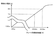
つぎに、本実施の形態にかかる、光検出手段4の動作を、図4に示す。図4は、横軸をプレート3に到達するプレート到達放射線量、縦軸を陽極出力電流Ipとする光検出手段4の特性を示す図である。なお、横軸および縦軸は、表示される量の対数表示となっており、縦軸は、電流の単位であるA(アンペア)、横軸は、放射線量の単位であるR(レントゲン)である。 Next, the operation of the light detection means 4 according to the present embodiment is shown in FIG. FIG. 4 is a diagram showing the characteristics of the light detection means 4 with the horizontal axis representing the amount of radiation reaching the plate 3 and the vertical axis representing the anode output current Ip. The horizontal axis and the vertical axis indicate logarithm of the displayed quantity, the vertical axis is A (ampere) which is a unit of current, and the horizontal axis is R (radiogram) which is a unit of radiation dose. is there.
図4には、陽極出力電流Ipとプレートへの到達放射線量の関係が、少なくとも500mRのプレート到達放射線量まで線形であることが示されている。従って、肥満した被写体であっても、陽極出力電流Ipが飽和することなく、正しいプレート到達放射線量を知ることができる。 FIG. 4 shows that the relationship between the anode output current Ip and the radiation dose reaching the plate is linear up to a radiation dose reaching the plate of at least 500 mR. Therefore, even for an obese subject, the correct radiation amount reaching the plate can be known without the anode output current Ip being saturated.
なお、プレート3を構成する輝尽性蛍光体層と封止フィルムとの間に間隙を設け、プレートを高画質化することもできる(例えば、特開平11―249243号公報参照)。この場合には、光検出手段4は、電流増倍率Gの設定を最適化することにより、陽極出力電流Ipの飽和を防止し、前述した構成を変更することなく、適正なプレート到達放射線量を出力することができる。 It should be noted that a gap can be provided between the photostimulable phosphor layer constituting the plate 3 and the sealing film to improve the image quality of the plate (see, for example, JP-A-11-249243). In this case, the light detection means 4 optimizes the setting of the current multiplication factor G to prevent saturation of the anode output current Ip, and to obtain an appropriate plate reaching radiation dose without changing the above-described configuration. Can be output.
すなわち、電流増倍率Gを、光電子増倍管24に印加される電圧HVの調整により最適化し、飽和のない画像情報を取得する。ここで、電流増倍率Gは、(1)式で現されるように、陽極出力電流Ipと陰極電流Ikとの比例計数をなし、2万〜20万倍の範囲に設定される。 That is, the current multiplication factor G is optimized by adjusting the voltage HV applied to the photomultiplier tube 24, and image information without saturation is acquired. Here, the current multiplication factor G is proportional to the anode output current Ip and the cathode current Ik and is set in the range of 20,000 to 200,000 times, as expressed by the equation (1).
ここで、輝尽性発光情報は、光検出手段4から対数変換回路5へ、広いダイナミックレンジに渡る電流信号として送信され、その後、対数変換されると同時に電流電圧変換され、帯域圧縮された電圧信号として、A/D変換器6へ送信される。
Here, the photostimulable luminescence information is transmitted from the light detection means 4 to the
A/D変換器6は、入力された電圧信号をデジタル信号へ変換するA/Dコンバータ、A/Dコンバータからのデジタル信号のサンプリング間隔および量子化ビット数を変更するデジタルフィルタを含む。A/D変換器6は、対数変換回路5から入力された電圧信号を、レーザ光の走査に同期した所定のサンプリング間隔で、1桁当たり1024ステップの分解能で量子化する。すなわち、ダイナミックレンジ4.3桁に渡る電圧信号を、0から4403のデジタル値へ割り当てる。
The A / D converter 6 includes an A / D converter that converts an input voltage signal into a digital signal, and a digital filter that changes the sampling interval and the number of quantization bits of the digital signal from the A / D converter. The A / D converter 6 quantizes the voltage signal input from the
また、4.3桁のダイナミックレンジの上限を越える電圧信号は、4403のデジタル値に割り当てを行い、4.3桁のダイナミックレンジの下限を下回る電圧信号は、0のデジタル値に割り当てを行う。そして、13ビットのデジタル情報に変換された輝尽性発光情報は、画像信号として後段の残光補正手段7に送信される。なお、電圧信号の範囲は上述した例に限定されず、例えば、5桁のダイナミックレンジの範囲に相当する電圧信号を、0から5119のデジタル値に割り当てるようにすることもできる。また、量子化ビット数は、13ビットに限定されず、例えば16ビットとすることもできる。 A voltage signal exceeding the upper limit of the 4.3 digit dynamic range is assigned to a digital value of 4403, and a voltage signal lower than the lower limit of the 4.3 digit dynamic range is assigned to a digital value of 0. Then, the photostimulable light emission information converted into 13-bit digital information is transmitted as an image signal to the afterglow correction means 7 at the subsequent stage. The range of the voltage signal is not limited to the above-described example. For example, a voltage signal corresponding to a 5-digit dynamic range can be assigned to a digital value from 0 to 5119. Further, the number of quantization bits is not limited to 13 bits, and may be 16 bits, for example.
ここで、残光補正手段7について説明する前に、輝尽発光の残光補正について述べる。輝尽発光に伴う残光成分は、画質の劣化を引き起こすので、電気的あるいは理論式を用いてデジタル的に、除去される。例えば、輝尽性蛍光体における残光を、励起時点における最高強度レベルから指数関数的に減衰するものとして、1つの指数関数により近似し、この近似特性に従って、画像信号を補正する画像読み取り方法が知られている(例えば、特許文献1参照)。これによれば、任意の走査点上の画素に発生した残光の減衰係数f(x)を、走査点の移動距離xの関数としてつぎの式(4)で近似される。 Here, before explaining the afterglow correcting means 7, afterglow light afterglow correction will be described. The afterglow component associated with the photostimulable emission causes deterioration of the image quality, and is thus removed digitally using an electrical or theoretical formula. For example, there is an image reading method in which the afterglow in the photostimulable phosphor is approximated by one exponential function, assuming that the afterglow decays exponentially from the highest intensity level at the time of excitation, and the image signal is corrected according to this approximate characteristic. It is known (see, for example, Patent Document 1). According to this, the attenuation coefficient f (x) of the afterglow generated in the pixel on an arbitrary scanning point is approximated by the following expression (4) as a function of the moving distance x of the scanning point.

この式(4)で、αは走査速度、τは発光寿命(励起光の照射が終了した後に、輝尽発光の強度が1/eになるまでの時間)、aは定数である。 In this formula (4), α is the scanning speed, τ is the emission lifetime (the time until the intensity of the stimulated emission becomes 1 / e after the irradiation of the excitation light is completed), and a is a constant.
また、輝尽性蛍光体における残光特性を2つ以上の指数関数の和に近似し、この近似特性に従って画像信号を補正する画像読み取り方法も知られている(例えば、特許文献2参照)。これによれば、任意の走査点上の画素に発生した画素の残光の減衰係数f(x)を、例えば、3つの指数関数の和により、走査点の移動距離xの関数として現し、つぎの式(5)で近似する。 Also known is an image reading method that approximates the afterglow characteristics of a photostimulable phosphor to the sum of two or more exponential functions and corrects the image signal according to the approximate characteristics (see, for example, Patent Document 2). According to this, the attenuation coefficient f (x) of the afterglow of a pixel generated in a pixel on an arbitrary scanning point is expressed as a function of the moving distance x of the scanning point by, for example, the sum of three exponential functions. (5)
この式(5)で、αは走査速度、τ、τ′、τ″は共に発光寿命、a、bおよびcは定数である。 In this equation (5), α is the scanning speed, τ, τ ′, τ ″ are all emission lifetimes, and a, b, and c are constants.
上述した式(4)および式(5)によれば、輝尽発光光量に比例する画像信号(以下、リニア画像信号と称する)L(x)から残光の影響を正しく補正した補正済リニア画像信号(以下、補正済リニア画像信号と称する)L(x)′を得るためには、走査点xのリニア画像信号L(x)に加えて、既に走査済みの位置x−1,x−2,…におけるリニア画像信号L(x−1)、L(x−2)、…も必要とされる。 According to the equations (4) and (5) described above, a corrected linear image in which the influence of afterglow is correctly corrected from an image signal (hereinafter referred to as a linear image signal) L (x) proportional to the amount of stimulated emission light. In order to obtain a signal (hereinafter referred to as a corrected linear image signal) L (x) ′, in addition to the linear image signal L (x) at the scanning point x, already scanned positions x−1, x−2 ,... Also require linear image signals L (x−1), L (x−2),.
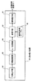
つづいて、図5に、残光補正手段7の構成を示す。残光補正手段7は、逆対数変換手段31、演算手段32および対数変換手段33を含む。A/D変換器6から逐次入力される画像信号をS(x)とすると、S(x)は、逆対数変換手段31により逐次逆対数変換され、リニア画像信号L(x)となる。
Next, FIG. 5 shows a configuration of the afterglow correcting means 7. The afterglow correction unit 7 includes an inverse
このリニア画像信号L(x)は、τおよびaの値に基づいて式(4)から算定される残光の減衰係数を用いて、演算手段32により残光が補正される。補正済リニア画像信号L(x)′は、対数変換手段33により逐次対数変換されて、補正済画像信号を現すデータ(以下、補正済画像信号と称する)S(x)′となる。この後、補正済画像信号S(x)′は、画像処理装置8に逐次送信される。
The afterglow of the linear image signal L (x) is corrected by the computing means 32 using the afterglow attenuation coefficient calculated from the equation (4) based on the values of τ and a. The corrected linear image signal L (x) ′ is sequentially logarithmically converted by the logarithmic conversion means 33 to become data (hereinafter referred to as a corrected image signal) S (x) ′ representing the corrected image signal. Thereafter, the corrected image signal S (x) ′ is sequentially transmitted to the
なお、逆対数変換手段31および対数変換手段33は、例えば、演算付加を減らして演算速度を向上するために、変換テーブルに結果をあらかじめ記憶し、このテーブルを適宜参照する構成とすることもできる。 The inverse logarithmic conversion means 31 and the logarithmic conversion means 33 may be configured to store the result in advance in a conversion table and refer to this table as appropriate, for example, in order to reduce calculation addition and improve the calculation speed. .
つづいて、演算手段32による残光の補正について詳細に説明する。まず、特許文献6に開示されるプレートを用いたプレート3では、任意の走査点上の画素に発生する残光の減衰特性は、つぎの式(8)で近似される。また、リニア画像信号L(x)と補正済リニア画像信号L(x)′との関係を、式(4)の残光の減衰係数f(x)を用いて離散的に現すと、つぎの式(9)となる。 Next, the afterglow correction by the calculation means 32 will be described in detail. First, in the plate 3 using the plate disclosed in Patent Document 6, the decay characteristic of afterglow generated in a pixel on an arbitrary scanning point is approximated by the following equation (8). Further, when the relationship between the linear image signal L (x) and the corrected linear image signal L (x) ′ is discretely expressed by using the afterglow attenuation coefficient f (x) of Expression (4), Equation (9) is obtained.
ここで、xnおよびxiは、それぞれ画素数nおよびiに比例する走査開始点からの距離、αは走査速度を現す。また、Δxは、サンプリングピッチである。 Here, xn and xi are distances from the scanning start point proportional to the number of pixels n and i, respectively, and α represents the scanning speed. Δx is a sampling pitch.
そして、演算量を減らすために、残光を現す式(9)の右辺の第2項を取り出して、n画素目の残光Z(n)を現す漸化式へ近似すると、つぎの式(10)となる。 Then, in order to reduce the amount of calculation, the second term on the right side of the equation (9) that expresses afterglow is extracted and approximated to a recurrence equation that expresses the afterglow Z (n) of the nth pixel. 10).
ここで、プレート3の残光特性を現す式(10)のパラメータBおよびDを実験的に求めると、B=9.3471×10⁻⁵、D=9.9819×10⁻¹となる。例えば、プレート3の読み取りが開始され、走査ライン上の最初の走査点である第1画素のリニア画像信号L(x1)が、演算手段32に入力される。第1画素よりも以前に走査した画素が存在しないため、第1画素の補正済リニア画像信号L(x1)′は、L(x1)と等しい。さらに、第2画素以降の補正済リニア画像信号L(x2)′、L(x3)′、・・・、L(xn)′も、つぎに示す表1のように順次求められる。
Here, when the parameters B and D of the equation (10) representing the afterglow characteristic of the plate 3 are experimentally obtained, B = 9.3471 × 10 −5 and D = 9.99819 × 10 −1 . For example, reading of the plate 3 is started, and the linear image signal L (x1) of the first pixel, which is the first scanning point on the scanning line, is input to the
なお、残光の減衰係数は、式(4)で近似されるものに限定されず、式(5)のように、残光の減衰係数を3つの指数関数で近似することもできる。例えば、特開平2002―020742号公報および特開平2002―006092号公報で開示されるプレートにおいては、任意の走査線上の画素に発生した残光係数は、つぎの式(11)で近似される。 Note that the afterglow attenuation coefficient is not limited to that approximated by Equation (4), and the afterglow attenuation coefficient can also be approximated by three exponential functions as in Equation (5). For example, in the plates disclosed in Japanese Patent Application Laid-Open Nos. 2002-020742 and 2002-006092, an afterglow coefficient generated in a pixel on an arbitrary scanning line is approximated by the following equation (11).
また、式(10)と同様に、演算量を減らす目的で、残光を現す式(9)の右辺の第2項を取り出して、n画素目の残光Z(n)を現す漸化式へ近似すると、上記の式(12)となる。 Similarly to equation (10), the second term on the right side of equation (9) representing afterglow is extracted for the purpose of reducing the amount of computation, and a recurrence equation representing afterglow Z (n) of the nth pixel. Is approximated to the above equation (12).
ここで、プレート3の残光特性を現す式(12)のパラメータB1、D1、B2、D2、B3およびD3を実験的に求めると、B1=1.00×10⁻⁶、D1=9.99×10⁻¹、B2=2.00×10⁻⁶、D2=9.97×10⁻¹、B3=5.00×10⁻⁶およびD3=9.92×10⁻¹となる。これらの定数を用いて、つぎの表2に示すように、補正済リニア画像信号L(x)′が順次求められる。 Here, when parameters B1, D1, B2, D2, B3, and D3 of the equation (12) representing the afterglow characteristic of the plate 3 are experimentally obtained, B1 = 1.00 × 10 −6, D1 = 9.99. X10-1, B2 = 2.00x10⁻⁶, D2 = 9.97x10⁻¹, B3 = 5.00x10⁻⁶ and D3 = 9.92x10⁻¹. Using these constants, corrected linear image signals L (x) ′ are sequentially obtained as shown in Table 2 below.
上述してきたように、本実施の形態1では、光検出手段4が4.3桁のダイナミックレンジを有することとしているので、標準体形の被写体のみならず、肥満した被写体の場合にも、プレート3の粒状性を変化させずに、しかも光検出手段4の出力が上限を越えて飽和し、後段で行われる残光補正手段7を用いた残光の補正が不適切に行われることを防止し、ひいては画像再生装置9で再生される放射線画像が、アーティファクト等により画質劣化することを防止することができる。
(実施の形態2)
ところで、上記実施の形態1では、光検出手段4を、4.3桁のダイナミックレンジを有することとして、肥満した被写体の場合にも、適正な残光補正が行えるようにしたが、光検出手段4を、標準体形の被写体に対する4.0桁のダイナミックレンジのままとして、肥満した被写体で出力に飽和を生じる場合に、残光補正を中止し、不適切な残光補正に伴う画質劣化を防止することもできる。そこで、本実施の形態2では、光検出手段4の出力が飽和状態にあるかどうかを判定し、残光補正を制御する場合を示すことにする。
As described above, in the first embodiment, since the light detection means 4 has a 4.3-digit dynamic range, the plate 3 is used not only for a standard-shaped subject but also for an obese subject. The afterglow correction using the afterglow correction unit 7 performed in the subsequent stage is prevented from being inappropriately performed without changing the graininess of the light, and the output of the
(Embodiment 2)
By the way, in the first embodiment, the light detection means 4 has a 4.3-digit dynamic range so that proper afterglow correction can be performed even in the case of an obese subject. 4 is left in the 4.0 digit dynamic range for a standard subject, and when output is saturated in an obese subject, the afterglow correction is stopped and image quality deterioration due to inappropriate afterglow correction is prevented. You can also Therefore, in the second embodiment, it is determined whether or not the output of the light detection means 4 is in a saturated state and the afterglow correction is controlled.
ここで、読み取り装置20は、光検出手段4が、標準体形の被写体に対する4.0桁のダイナミックレンジのものとし、残光補正手段7の代わりに、残光補正手段71が用いられる。その他の構成は、図1に示したものと全く同様であるので説明を省略する。
Here, in the reading device 20, the
図6は、残光補正手段71の構成を示す図である。残光補正手段71は、図5に示される残光補正手段7を構成する逆対数変換手段31、演算手段32および対数変換手段33に加えて、すべての画像信号を一時的に記憶する入力バッファ34、画像信号中の画素の飽和を逐次判定する飽和逐次判定手段35および残光補正後の画像信号Sを一時的に記憶する出力バッファ36を有している。
FIG. 6 is a diagram showing a configuration of the afterglow correction unit 71. The afterglow correction unit 71 is an input buffer that temporarily stores all image signals in addition to the inverse
なお、ここで言う飽和とは、走査点x上の画素において、プレート3に到達する到達放射線量が、光検出手段4のダイナミックレンジ4.0桁にわたる検出領域の上限を越えたため、得られた画像信号値S(x)が、13ビットの量子化ビット数の取りうる最大値である4403に揃えられる場合を言う。 Note that the saturation mentioned here was obtained because the amount of radiation reaching the plate 3 exceeded the upper limit of the detection region over the dynamic range of 4.0 digits of the light detection means 4 in the pixel on the scanning point x. This is a case where the image signal value S (x) is aligned with 4403 which is the maximum value that the number of 13-bit quantization bits can take.
つづいて、残光補正手段71を用いた残光の補正について説明する。まず、A/D変換器6から逐次入力される画像信号は、入力バッファ34に記憶される。飽和逐次判定手段35は、入力バッファ34の画像情報を、順番に従い1画素だけ取り出す。そして、取り出した画像信号S(x)が、つぎの式(13)を満足するかどうかを判定する。
Subsequently, afterglow correction using the afterglow correcting means 71 will be described. First, image signals sequentially input from the A / D converter 6 are stored in the
S(x)=4403 ―――――(13)
ここで、画像信号S(x)が、式(13)を満足しない場合は、画像信号S(x)は、飽和していないので、画像信号S(x)を後段の逆対数変換手段31へ逐次送信する。そして、画像信号S(x)は、実施の形態1と同様に、残光の補正が行われ、出力バッファ36に記憶される。その後、つぎの1画素を入力バッファ34から取り出して、上述した手順を繰り返し行い、さらに、すべての画像信号を入力バッファ34から取り出して補正を終了した後で、出力バッファ36に記憶されている、残光が補正された画像信号を、後段の画像処理装置8へ一括して送る。
S (x) = 4403 ――――― (13)
Here, when the image signal S (x) does not satisfy the expression (13), the image signal S (x) is not saturated, so that the image signal S (x) is sent to the inverse logarithmic conversion means 31 in the subsequent stage. Send sequentially. The image signal S (x) is corrected for afterglow and stored in the output buffer 36 as in the first embodiment. Thereafter, the next pixel is taken out from the
また、画像信号S(x)が、式(13)を満足する場合は、画像信号S(x)は、飽和しているので、出力バッファ36の内容を消去し、入力バッファ34に残っている未補正の画像信号を、後段の画像処理装置8へ一括して送る。
When the image signal S (x) satisfies the expression (13), the image signal S (x) is saturated, so the contents of the output buffer 36 are erased and remain in the
上述してきたように、本実施の形態2では、残光補正手段71が、画像信号S(x)が飽和しいるかどうかを、残光の補正中に逐次判定し、飽和した画像信号S(x)があれば、補正を中止し、未補正のすべての画像信号が後段の装置へ送られるので、残光の影響を誤って補正してアーティファクトが生じ、診断等へ悪影響が及ぼすことを防止する。
(実施の形態3)
ところで、上記実施の形態2では、飽和を、残光の補正中に逐次判定することとしたが、一括して飽和の判定を行うこともできる。そこで、本実施の形態3では、飽和の判定を一括して行い、その後に、未補正の画像信号を後段へ送信する場合を示すことにする。
As described above, in the second embodiment, the afterglow correcting unit 71 sequentially determines whether or not the image signal S (x) is saturated during the afterglow correction, and the saturated image signal S (x ), The correction is canceled and all uncorrected image signals are sent to the subsequent device, so that the influence of afterglow is corrected by mistake, resulting in artifacts and preventing adverse effects on diagnosis and the like. .
(Embodiment 3)
In the second embodiment, the saturation is sequentially determined during the afterglow correction. However, the saturation can also be determined collectively. Therefore, in the third embodiment, a case where saturation determination is collectively performed and then an uncorrected image signal is transmitted to the subsequent stage will be described.
ここで、読み取り装置20は、光検出手段4が、標準体形の被写体に対する4.0桁のダイナミックレンジのものとし、残光補正手段7の代わりに、残光補正手段72が用いられる。その他の構成は、図1に示したものと全く同様であるので説明を省略する。
Here, in the reading device 20, the
図7は、残光補正手段72の構成を示す図である。残光補正手段72は、図5に示される残光補正手段7を構成する逆対数変換手段31、演算手段32および対数変換手段33に加えて、すべての画像信号を一時的に記憶する入力バッファ34および全画像信号において飽和する画像信号の有無を検出する飽和一括判定手段37を有している。
FIG. 7 is a diagram showing a configuration of the afterglow correcting means 72. The afterglow correction unit 72 is an input buffer that temporarily stores all image signals in addition to the inverse
つづいて、残光補正手段72を用いた残光の補正について説明する。A/D変換器6から逐次入力される画像信号は、入力バッファ34に記憶される。飽和一括判定手段37は、入力バッファ34の画像情報を、順番に従い1画素だけ取り出す。そして、取り出した画像信号S(x)が、実施の形態2で示した式(13)を満足するかどうかを判定する。
Subsequently, afterglow correction using the afterglow correcting means 72 will be described. Image signals sequentially input from the A / D converter 6 are stored in the
ここで、画像信号S(x)が、式(13)を満足しない場合は、画像信号S(x)は、飽和していないので、つぎの1画素を取り出して同様に判定する。全画像情報の判定が終了した後に、画像信号を、入力バッファ34から逆対数変換手段31へ逐次送信し、実施の形態1と同様に残光を補正し、この補正された画像信号を後段の画像処理装置8へ逐次送信する。
Here, when the image signal S (x) does not satisfy the expression (13), the image signal S (x) is not saturated. After the determination of all the image information is completed, the image signal is sequentially transmitted from the
また、画像信号S(x)が、式(13)を満足する場合は、画像信号S(x)は、飽和しているので、飽和する画像信号の有無を検出するのを中止して、入力バッファ34に残っている未補正の画像信号を、後段の画像処理装置8へ一括して送信する。
If the image signal S (x) satisfies the expression (13), the image signal S (x) is saturated. The uncorrected image signal remaining in the
上述してきたように、本実施の形態3では、残光補正手段72は、すべての画像信号において、飽和する画像信号の有無が補正前に一括して判定され、飽和した画像信号S(x)があれば、補正を開始せずに、未補正の画像信号が後段の装置へ送信されるので、残光の影響を誤って補正してアーティファクトが生じ、診断等へ悪影響が及ぼすことを防止する。
(実施の形態4)
ところで、上記実施の形態1では、読み取り装置20の出力でもある残光補正手段7の出力は、ダイナミックレンジ4.3桁の信号範囲を、量子化ビット数が13ビットの4403段階の信号としている。他方、画像処理装置8および画像再生装置9も前記出力に対応したものとすることもできるが、従来から用いられている、ダイナミックレンジ4.0桁の信号範囲を1桁あたり1024ステップで量子化した、量子化ビット数が12ビットの画像信号に対応する画像処理装置8および画像再生装置9を用いることもできる。そこで、本実施の形態4では、残光補正手段7および画像処理装置8の間に、画像信号を現すデータのビット数を削減するビット数削減手段を設け、従来型の画像処理装置8と量子化ビット数を一致させる場合を示すことにする。
As described above, in the third embodiment, the afterglow correction unit 72 determines whether or not there is a saturated image signal in all image signals before correction, and the saturated image signal S (x) If there is, an uncorrected image signal is transmitted to the subsequent device without starting correction, so that the influence of afterglow is erroneously corrected to prevent artifacts and prevent adverse effects on diagnosis, etc. .
(Embodiment 4)
By the way, in Embodiment 1 described above, the output of the afterglow correction means 7 that is also the output of the reading device 20 uses a signal range of 4.3 digits in the dynamic range as a 4403-stage signal with a quantization bit number of 13 bits. . On the other hand, the
このビット数削減手段は、残光補正手段7から出力される画像信号が、ダイナミックレンジ4.3桁の信号範囲を、量子化ビット数13ビットの4403段階で現していることを考慮し、1桁あたり1024段階の分解能を保ちつつ、ダイナミックレンジ4.3桁の信号範囲から、最適な4.0桁の画像信号を切り出し、12ビットの量子化ビット数である4096段階に対応づけることにより行われる。 This bit number reduction means considers that the image signal output from the afterglow correction means 7 represents a signal range of 4.3 digits in the dynamic range in 4403 stages with a quantization bit number of 13 bits. While maintaining the resolution of 1024 steps per digit, the optimum 4.0 digit image signal is cut out from the signal range of 4.3 digits of dynamic range, and is associated with 4096 steps, which is the number of quantization bits of 12 bits. Is called.
図8に、ビット数削減手段73の構成を示す。ビット数削減手段73は、バッファ38、画像範囲判定手段39、画像範囲切り出し手段40、フラグ81、演算手段32および対数変換手段33を含む。なお、ビット数削減手段73は、残光補正手段7の出力および画像処理装置8の入力の間に設けられる。
FIG. 8 shows the configuration of the bit number reduction means 73. The bit number reduction means 73 includes a
ビット数削減手段73は、残光補正手段7から逐次入力される量子化ビット数が13ビットの画像信号を、バッファ38に記憶する。なお、12ビットの画像信号をS12(x)、13ビットの画像信号をS13(x)で現し、以後区別する。また、フラグ81は、フラグ低が、0桁から0.3桁の範囲に画像信号が存在するかどうかを示すフラグで、初期値をオフとし、フラグ高が、4.0桁から4.3桁の範囲に画像信号が存在するかどうかを示すフラグで、これも初期値をオフとする。
The bit number reduction unit 73 stores in the
画像範囲判定手段39は、バッファ38から量子化ビット数が13ビットの画像信号を1画素ずつ取り出して、この画像信号がつぎに示す式(14)および式(15)を満足するかどうかを判定する。
The image range determination means 39 extracts an image signal having a quantization bit number of 13 bits from the
ここで、画像信号が式(14)を満足する場合には、画像信号S13(x)は、0桁から0.3桁の範囲の画像信号を含むので、フラグ81のフラグ低をオンにする。また、画像信号が式(15)を満足する場合には、画像信号S13(x)は、4.0桁から4.3桁の範囲の画像情報を含むので、フラグ81のフラグ高をオンにする。そして、上述した判定を、すべての画像情報に対して終了するまで、繰り返す。
Here, when the image signal satisfies the equation (14), the image signal S 13 (x) includes the image signal in the range of 0 digit to 0.3 digit, so that the flag low of the
その後、画像範囲切り出し手段40は、フラグ81を参照する。ここで、フラグ低がオフで、かつフラグ高がオンの場合には、全画像信号は、0桁から0.3桁の範囲の画像信号を含まず、かつ4.0桁から4.3桁の範囲の画像信号を含む。従って、バッファ38から画像信号を1画素ずつ取り出して、画像信号S13(x)を式(16)に代入し、0.3桁から4.3桁の範囲を、0桁から4.0桁の範囲へ切り出し、12ビットの画像信号を画像処理装置8へ逐次送信する。そして、すべての画像信号にたいして切り出しを終える迄、上述した切り出しを繰り返す。
Thereafter, the image
また、画像信号が4.0桁から4.3桁の範囲を有する画素は、放射線が直接照射された画素が殆どであると考えられ、この様な画素は、被写体の情報を殆ど含まない。従って、4.0桁から4.3桁の範囲の画像信号は、0桁から0.3桁の範囲の画像信号よりも、診断に必要な情報を含む可能性が低い。 Further, it is considered that most pixels having an image signal in the range of 4.0 digits to 4.3 digits are directly irradiated with radiation, and such pixels contain almost no subject information. Accordingly, an image signal in the range of 4.0 digits to 4.3 digits is less likely to contain information necessary for diagnosis than an image signal in the range of 0 digits to 0.3 digits.
ここで、フラグ81のフラグ低がオンの場合には、全画像信号は、0桁から0.3桁の範囲の画像信号を含むので、診断に必要な情報を含む可能性が高く、0桁から0.3桁の範囲を含むように画像信号の切り出しを行う。すなわち、バッファ38から画像信号を1画素ずつ取り出して、この画像信号S13(x)を式(17)に代入して、0桁から4.0桁の画像範囲を切り出し、対応する12ビットの画像信号を、後段の画像処理装置8へ送信する。そして、すべての画像信号の切り出しを終える迄、上述の操作を繰り返す。
Here, when the flag low of the
また、フラグ81のフラグ高およびフラグ低が共にオフの場合には、フラグ低がオンの場合と同様に、0桁から4.0桁の画像範囲を切り出し、画像処理装置8へ逐次送信する。
When both the flag high and flag low of the
上述してきたように、本実施の形態4では、ビット数削減手段73は、量子化ビット数が13ビットの画像信号から、診断に有用と思われる、ダイナミックレンジ4.0桁に相当する、量子化ビット数が12ビットの画像信号を取り出して出力することとしているので、従来から用いられている市販の、量子化ビット数が12ビット対応の画像処理装置8および画像再生装置9を用いることができ、コスト的に有利なものとすることができる。
(実施の形態5)
ところで、上記実施の形態1〜4では、光検出手段4は、入射光量に対して出力される電圧信号が線形であるとしたが、さらに肥満した被写体では、入射光量がダイナミックレンジ4.3桁を越え、入射光量に対して出力される電圧信号は非線形となる。そして、後段の画像処理装置8および画像再生装置9で行われる処理が、適正に行われなくなる。そこで、本実施の形態5では、信号処理により、光検出手段4の出力を入射光量に対して線形なものとして、後段で行われる処理が、適正に行われるようにする。
As described above, in the fourth embodiment, the bit number reduction unit 73 uses a quantum range corresponding to a dynamic range of 4.0 digits, which is considered useful for diagnosis, from an image signal having a quantization bit number of 13 bits. Since the image signal having the quantization bit number of 12 bits is taken out and output, the commercially available
(Embodiment 5)
By the way, in the first to fourth embodiments, the voltage signal output with respect to the incident light amount is linear in the light detection means 4. However, in an obese subject, the incident light amount has a dynamic range of 4.3 digits. The voltage signal output with respect to the incident light quantity is nonlinear. Then, the processes performed in the subsequent
図9に、本実施の形態5にかかる読み取り装置91のブロック図を示す。読み取り装置91は、光検出手段94、対数変換回路95、A/D変換器96、参照手段42、線形性回復テーブル41および残光補正手段97を含む。
FIG. 9 shows a block diagram of a reading device 91 according to the fifth embodiment. The reading device 91 includes a light detection means 94, a
光検出手段94は、入射光量がダイナミックレンジ4.3桁から4.5桁の範囲において、出力の電流信号が非線形および1対1の関係にあり、2mA〜2.5mAの範囲の電流信号を出力する。また、対数変換回路95は、100nA〜2.5mAの入力範囲を有し、A/D変換器96は、ダイナミックレンジ4.5桁の範囲の電圧信号を、0〜4607のデジタル値に変換する。
In the light detection means 94, the output current signal is nonlinear and has a one-to-one relationship when the incident light quantity is in the dynamic range of 4.3 to 4.5 digits, and the current signal in the range of 2 mA to 2.5 mA is output. Output. The
参照手段42は、A/D変換器96の出力データに対して、線形性回復テーブル41を参照して、新たな線形データを生成し、残光補正手段97へ出力する。線形性回復テーブル41は、光検出手段94の非線形特性に基づいた、入射光量の非線形なデジタル値を線形なデジタル値に変換するLUT(Look Up Table)である。図10に、線形性回復テーブル41の一例を示す。横軸は、A/D変換器96からの入力デジタル値を現し、縦軸は、残光補正手段97へ出力される出力デジタル値を現している。線形性回復テーブル41は、実験的に取得される光検出手段94の非線形特性を打ち消す様に決定される。
The reference means 42 refers to the linearity recovery table 41 with respect to the output data of the A /
ここで、A/D変換器6から逐次入力される入射光量の非線形なデジタル情報は、参照手段42により、線形性回復テーブル41を用いて、線形なデジタル情報とされ、その後、残光補正手段97に出力される。 Here, the non-linear digital information of the incident light quantity sequentially input from the A / D converter 6 is converted into linear digital information by using the linearity recovery table 41 by the reference means 42, and then the afterglow correction means. 97 is output.
上述してきたように、本実施の形態5では、参照手段42により、入射光量の非線形なデジタル値を線形なデジタル値に変換して残光補正手段97に出力することとしているので、より太った被写体を撮影した場合にも残光の補正を適正に行うことができる。
As described above, in the fifth embodiment, the
また、本実施の形態5では、参照手段42および線形性回復テーブル41を、A/D変換器96および残光補正手段97の間に配設することとしたが、これらを、残光補正手段97に含めることもできる。
In the fifth embodiment, the
図11は、参照手段42および線形性回復テーブル41の機能を含む残光補正手段98の例である。読み取り装置91のその他構成は、図9で示したものと同一であるので説明を省略する。残光補正手段98は、参照手段44、変換テーブル43、演算手段32および対数変換手段33を含む。演算手段および対数変換手段33は、図5に示した残光補正手段7のものと同一である。
FIG. 11 is an example of the afterglow correction unit 98 including the functions of the
変換テーブル43は、図9の線形性回復テーブル41および図5の逆対数変換手段31の機能を合わせ持つもので、入射光量に対して非線形なデジタル値を、光検出手段94の非線形特性に基づいて、線形なデジタル値の画像信号へ変換すると同時に、この画像信号をリニヤ画像信号へ逆対数変換する。
The conversion table 43 has the functions of the linearity recovery table 41 in FIG. 9 and the inverse
参照手段44は、変換テーブル43を参照して、入力した非線形のデジタル値を、入射光量に比例したリニヤ画像信号とする。このリニヤ画像信号は、図5に示した演算手段32および対数変換手段33により、残光の補正がなされ、後段の画像処理装置8へ逐次送信される。これにより、実施の形態5と同様のことを、簡易な構成で実現することができる。
The
1 放射線発生装置
2 被写体
3 プレート
4、94 光検出手段
5、95 対数変換回路
6、96 A/D変換器
7、71、72、97、98 残光補正手段
8 画像処理装置
9 画像再生装置
10 走査手段
11 陰極
12 集束部
13 ダイノード部
14 高電圧電源
15 陽極
16 ブリーダ回路
20、91 読み取り装置
21 集光体
22 フィルタ
23 光電変換器
24 光電子増倍管
25 周辺回路
31 逆対数変換手段
32 演算手段
33 対数変換手段
34 入力バッファ
35 飽和逐次判定手段
36 出力バッファ
37 飽和一括判定手段
38 バッファ
39 画像範囲判定手段
40 画像範囲切り出し手段
41 線形性回復テーブル
42、44 参照手段
43 変換テーブル
73 ビット数削減手段
81 フラグ
DESCRIPTION OF SYMBOLS 1 Radiation generator 2 Subject 3
Claims (6)
前記走査を構成する走査点ごとに、前記励起光により生じる輝尽発光を検出する、4.3桁以上のダイナミックレンジを有する光検出手段と、
前記検出された輝尽発光情報から、前記輝尽発光が生じる走査点と異なる走査点からの残光を除去し補正する残光補正手段と、
を備えることを特徴とする放射線画像読取装置。 Scanning means for scanning the stimulable phosphor plate in which the radiation image information is accumulated, with excitation light;
Photodetection means having a dynamic range of 4.3 digits or more for detecting stimulated luminescence generated by the excitation light for each scanning point constituting the scan;
Afterglow correction means for removing and correcting afterglow from a scanning point different from the scanning point where the stimulated light emission occurs from the detected photostimulated light emission information,
A radiation image reading apparatus comprising:
前記走査を構成する走査点ごとに、前記励起光により生じる輝尽発光を検出する光検出手段と、
前記検出された輝尽発光情報から、前記輝尽発光が生じる走査点と異なる走査点からの残光を除去し補正する残光補正手段と、
を備える放射線画像読取装置であって、
前記残光補正手段は、前記補正を行いつつ、前記走査点ごとに、前記光検出手段が飽和しているかどうかを判定し、前記飽和が生じた際には、前記補正を中止し、前記飽和が生じない際には、前記補正を続行する飽和逐次判定手段を備えることを特徴とする放射線画像読取装置。 Scanning means for scanning the stimulable phosphor plate in which the radiation image information is accumulated, with excitation light;
For each scanning point constituting the scanning, a light detecting means for detecting stimulated light emission generated by the excitation light, and
Afterglow correction means for removing and correcting afterglow from a scanning point different from the scanning point where the stimulated light emission occurs from the detected photostimulated light emission information,
A radiation image reading apparatus comprising:
The afterglow correction unit determines whether the light detection unit is saturated for each scanning point while performing the correction. When the saturation occurs, the correction is stopped, and the saturation is performed. A radiological image reading apparatus, comprising: a saturation sequential determination unit that continues the correction when the error does not occur.
前記走査を構成する走査点ごとに、前記励起光により生じる輝尽発光を検出する光検出手段と、
前記検出された輝尽発光情報から、前記輝尽発光が生じる走査点と異なる走査点からの残光を除去し補正する残光補正手段と、
を備える放射線画像読取装置であって、
前記残光補正手段は、前記補正を行う前に、すべての前記走査点において、前記光検出手段が飽和しているかどうかを一括判定し、前記一括判定に基づいて、前記飽和が生じている際には、前記補正を中止し、前記飽和が生じていない際には、前記補正を行う飽和一括判定手段を備えることを特徴とする放射線画像読取装置。 Scanning means for scanning the stimulable phosphor plate in which the radiation image information is accumulated, with excitation light;
For each scanning point constituting the scanning, a light detecting means for detecting stimulated light emission generated by the excitation light, and
Afterglow correction means for removing and correcting afterglow from a scanning point different from the scanning point where the stimulated light emission occurs from the detected photostimulated light emission information,
A radiation image reading apparatus comprising:
The afterglow correction unit collectively determines whether the light detection unit is saturated at all the scanning points before performing the correction, and when the saturation occurs based on the batch determination. The radiographic image reading apparatus further comprises a saturation batch determination unit that stops the correction and performs the correction when the saturation does not occur.
前記走査を構成する走査点ごとに、前記励起光により生じる輝尽発光を検出する光検出手段と、
前記検出された輝尽発光情報から、前記輝尽発光が生じた走査点と異なる走査点からの残光を除去し補正する残光補正手段と、
前記補正された輝尽発光情報のビット数を削減するビット削減手段と、
を備えることを特徴とする放射線画像読取装置。 Scanning means for scanning the stimulable phosphor plate in which the radiation image information is accumulated, with excitation light;
For each scanning point constituting the scanning, a light detecting means for detecting stimulated light emission generated by the excitation light, and
Afterglow correction means for removing and correcting afterglow from a scanning point different from the scanning point where the stimulated light emission has occurred, from the detected light emission information.
Bit reduction means for reducing the number of bits of the corrected stimulated light emission information;
A radiation image reading apparatus comprising:
前記走査を構成する走査点ごとに、前記励起光により生じる輝尽発光を検出する光検出手段と、
前記光検出手段の非線形な読み取り特性に基づいて、前記輝尽発光情報の線形性を回復する線形性回復手段と、
前記検出された輝尽発光情報から、前記輝尽発光が生じた走査点と異なる走査点からの残光を除去し補正する残光補正手段と、
を備えることを特徴とする放射線画像読取装置。 Scanning means for scanning the stimulable phosphor plate in which the radiation image information is accumulated, with excitation light;
For each scanning point constituting the scanning, a light detecting means for detecting stimulated light emission generated by the excitation light, and
Linearity recovery means for recovering the linearity of the photostimulated luminescence information based on the non-linear reading characteristics of the light detection means;
Afterglow correction means for removing and correcting afterglow from a scanning point different from the scanning point where the stimulated light emission has occurred, from the detected light emission information.
A radiation image reading apparatus comprising:
前記走査を構成する走査点ごとに、前記励起光により生じる輝尽発光を検出する光検出手段と、
前記検出された輝尽発光情報から、前記輝尽発光が生じた走査点と異なる走査点からの残光を除去し補正する残光補正手段と、
を備える放射線画像読取装置であって、
前記残光補正手段は、前記光検出手段の非線形な読み取り特性に基づいて、前記輝尽発光情報を線形性を回復する線形性回復手段を備えることを特徴とする放射線画像読取装置。 Scanning means for scanning the stimulable phosphor plate in which the radiation image information is accumulated, with excitation light;
For each scanning point constituting the scanning, a light detecting means for detecting stimulated light emission generated by the excitation light, and
Afterglow correction means for removing and correcting afterglow from a scanning point different from the scanning point where the stimulated light emission has occurred, from the detected light emission information.
A radiation image reading apparatus comprising:
The afterglow correcting means includes a linearity recovery means for recovering the linearity of the photostimulated luminescence information based on a non-linear reading characteristic of the light detecting means.
Priority Applications (1)
| Application Number | Priority Date | Filing Date | Title |
|---|---|---|---|
| JP2003325690A JP2005091815A (en) | 2003-09-18 | 2003-09-18 | Radiation image reader |
Applications Claiming Priority (1)
| Application Number | Priority Date | Filing Date | Title |
|---|---|---|---|
| JP2003325690A JP2005091815A (en) | 2003-09-18 | 2003-09-18 | Radiation image reader |
Publications (2)
| Publication Number | Publication Date |
|---|---|
| JP2005091815A true JP2005091815A (en) | 2005-04-07 |
| JP2005091815A5 JP2005091815A5 (en) | 2006-10-19 |
Family
ID=34456069
Family Applications (1)
| Application Number | Title | Priority Date | Filing Date |
|---|---|---|---|
| JP2003325690A Pending JP2005091815A (en) | 2003-09-18 | 2003-09-18 | Radiation image reader |
Country Status (1)
| Country | Link |
|---|---|
| JP (1) | JP2005091815A (en) |
Cited By (3)
| Publication number | Priority date | Publication date | Assignee | Title |
|---|---|---|---|---|
| KR100755405B1 (en) * | 2006-09-14 | 2007-09-04 | 엘지전자 주식회사 | Filter and plasma display device thereof |
| JP2010528287A (en) * | 2007-05-21 | 2010-08-19 | ケーエルエー−テンカー・コーポレーション | Inspection system and method for extending the detection range of an inspection system by forcing the photodetector to a non-linear region |
| CN103405241A (en) * | 2013-07-21 | 2013-11-27 | 西北工业大学 | Detector afterglow correction method for ray imaging |
Citations (3)
| Publication number | Priority date | Publication date | Assignee | Title |
|---|---|---|---|---|
| JPS6218536A (en) * | 1985-07-18 | 1987-01-27 | Fuji Photo Film Co Ltd | Reading method for radiation image information |
| JP2002057840A (en) * | 2000-08-07 | 2002-02-22 | Fuji Photo Film Co Ltd | Reading device of picture image |
| JP2002142080A (en) * | 2000-11-02 | 2002-05-17 | Konica Corp | Radiographic picture reader and radiographic picture read method |
-
2003
- 2003-09-18 JP JP2003325690A patent/JP2005091815A/en active Pending
Patent Citations (3)
| Publication number | Priority date | Publication date | Assignee | Title |
|---|---|---|---|---|
| JPS6218536A (en) * | 1985-07-18 | 1987-01-27 | Fuji Photo Film Co Ltd | Reading method for radiation image information |
| JP2002057840A (en) * | 2000-08-07 | 2002-02-22 | Fuji Photo Film Co Ltd | Reading device of picture image |
| JP2002142080A (en) * | 2000-11-02 | 2002-05-17 | Konica Corp | Radiographic picture reader and radiographic picture read method |
Cited By (4)
| Publication number | Priority date | Publication date | Assignee | Title |
|---|---|---|---|---|
| KR100755405B1 (en) * | 2006-09-14 | 2007-09-04 | 엘지전자 주식회사 | Filter and plasma display device thereof |
| JP2010528287A (en) * | 2007-05-21 | 2010-08-19 | ケーエルエー−テンカー・コーポレーション | Inspection system and method for extending the detection range of an inspection system by forcing the photodetector to a non-linear region |
| CN103405241A (en) * | 2013-07-21 | 2013-11-27 | 西北工业大学 | Detector afterglow correction method for ray imaging |
| CN103405241B (en) * | 2013-07-21 | 2015-07-08 | 西北工业大学 | Detector afterglow correction method for ray imaging |
Similar Documents
| Publication | Publication Date | Title |
|---|---|---|
| JP4346968B2 (en) | Radiation imaging method, radiation imaging apparatus, and computer program | |
| JP5089210B2 (en) | Image sensor image processing method | |
| JP5013718B2 (en) | Radiation image acquisition apparatus and method | |
| US8452069B2 (en) | Method of eliminating effect of afterglow on radiation image read out of photostimulable phosphor screen | |
| JP2005091815A (en) | Radiation image reader | |
| JPH05293095A (en) | Image display method | |
| JP2000030046A (en) | Radiation image detecting and processing apparatus | |
| JP3945976B2 (en) | Image display method and apparatus | |
| US6781603B2 (en) | Image display method and apparatus | |
| JP2000244824A (en) | Pixel signal correcting method, its device and solid-state detector to be used for the same | |
| JPH0661325B2 (en) | Radiation image information processing method | |
| JP2012120200A (en) | Photographic device, image processing device, photographic system, radiographic device, and image processing method | |
| JP4031720B2 (en) | Sharpness correction method and apparatus in image reading apparatus | |
| JP2003199733A (en) | X-ray image memory, method of using x-ray image memory, method of examining subject with subtraction angiographic principle and x-ray image detector | |
| JPS6262376B2 (en) | ||
| JPH04314432A (en) | Method and apparatus for photographing and reading radiation image | |
| JP3903406B2 (en) | Image information reading method and apparatus | |
| JP2561159B2 (en) | Radiation image reader | |
| JP3353499B2 (en) | X-ray imaging device | |
| JPH10232452A (en) | Method and device for reading radiograph information | |
| JPS63153048A (en) | Radiation image data reading method and apparatus | |
| Oernhed et al. | Application of direct image plate scanning for recording and evaluation of flash x-ray images | |
| JPH08286292A (en) | Radiation image reader | |
| JP2002334329A (en) | Image processor and image processing method | |
| JPH07225437A (en) | Radiation image reading device |
Legal Events
| Date | Code | Title | Description |
|---|---|---|---|
| A521 | Request for written amendment filed |
Free format text: JAPANESE INTERMEDIATE CODE: A523 Effective date: 20060906 |
|
| A621 | Written request for application examination |
Free format text: JAPANESE INTERMEDIATE CODE: A621 Effective date: 20060906 |
|
| A977 | Report on retrieval |
Free format text: JAPANESE INTERMEDIATE CODE: A971007 Effective date: 20091029 |
|
| A131 | Notification of reasons for refusal |
Free format text: JAPANESE INTERMEDIATE CODE: A131 Effective date: 20091110 |
|
| A02 | Decision of refusal |
Free format text: JAPANESE INTERMEDIATE CODE: A02 Effective date: 20100323 |