JP2005080614A - Float for fishing - Google Patents
Float for fishing Download PDFInfo
- Publication number
- JP2005080614A JP2005080614A JP2003318954A JP2003318954A JP2005080614A JP 2005080614 A JP2005080614 A JP 2005080614A JP 2003318954 A JP2003318954 A JP 2003318954A JP 2003318954 A JP2003318954 A JP 2003318954A JP 2005080614 A JP2005080614 A JP 2005080614A
- Authority
- JP
- Japan
- Prior art keywords
- fishing
- main body
- float
- holding rod
- separator
- Prior art date
- Legal status (The legal status is an assumption and is not a legal conclusion. Google has not performed a legal analysis and makes no representation as to the accuracy of the status listed.)
- Pending
Links
Images


Classifications
-
- A—HUMAN NECESSITIES
- A01—AGRICULTURE; FORESTRY; ANIMAL HUSBANDRY; HUNTING; TRAPPING; FISHING
- A01K—ANIMAL HUSBANDRY; CARE OF BIRDS, FISHES, INSECTS; FISHING; REARING OR BREEDING ANIMALS, NOT OTHERWISE PROVIDED FOR; NEW BREEDS OF ANIMALS
- A01K93/00—Floats for angling, with or without signalling devices
-
- A—HUMAN NECESSITIES
- A01—AGRICULTURE; FORESTRY; ANIMAL HUSBANDRY; HUNTING; TRAPPING; FISHING
- A01K—ANIMAL HUSBANDRY; CARE OF BIRDS, FISHES, INSECTS; FISHING; REARING OR BREEDING ANIMALS, NOT OTHERWISE PROVIDED FOR; NEW BREEDS OF ANIMALS
- A01K91/00—Lines
- A01K91/03—Connecting devices
- A01K91/04—Connecting devices for connecting lines to hooks or lures
-
- Y—GENERAL TAGGING OF NEW TECHNOLOGICAL DEVELOPMENTS; GENERAL TAGGING OF CROSS-SECTIONAL TECHNOLOGIES SPANNING OVER SEVERAL SECTIONS OF THE IPC; TECHNICAL SUBJECTS COVERED BY FORMER USPC CROSS-REFERENCE ART COLLECTIONS [XRACs] AND DIGESTS
- Y10—TECHNICAL SUBJECTS COVERED BY FORMER USPC
- Y10S—TECHNICAL SUBJECTS COVERED BY FORMER USPC CROSS-REFERENCE ART COLLECTIONS [XRACs] AND DIGESTS
- Y10S43/00—Fishing, trapping, and vermin destroying
Abstract
Description
本発明は、釣りの際に使用される浮きに関するものである。 The present invention relates to a float used for fishing.
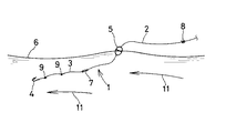
釣りのジャンルに「浮き釣り」というものがある。浮き釣りは、文字通り「浮き」と称されるアイテムを用いて魚を釣ろうとするものである。図9は、一般的な浮き釣りの仕掛けによる釣りの様子を示す模式図である。 There is a fishing genre called “floating fishing”. Floating fishing is intended to fish a fish using an item that is literally called “floating”. FIG. 9 is a schematic diagram showing a state of fishing by a general floating fishing device.
同図が示すように浮き釣りでは、仕掛け1は、道糸2と、連結具7(通常「サルカン」と称される。)を介して道糸2に連結されたハリス3と、ハリス3の先端に設けられた釣針4と、道糸2に装着された浮き5とを有する。浮き5の装着態様は従来から種々提案されているが、この仕掛け1では、浮き5はいわゆる中通しタイプのものであって、道糸2は、浮き5の内部に挿通されており、浮き5は、道糸2に沿って自在にスライドするようになっている。ただし、一般に道糸2には浮止具8が設けられ、これにより浮き5は、サルカン7と浮止具8との間でスライドする。また、浮き5は、海中に投入された状態で所定の浮力を備え、これにより、海面6に浮かぶことになる。さらに、仕掛け1が海中で安定的に配置されるために、ハリス3には、錘9(通常「ガン玉」と称される。)が適宜装着される。
As shown in the figure, in floating fishing, the
このように構成された仕掛け1が海中に投入されると、釣針4、ハリス3、ガン玉9、サルカン7等に作用する重力によって釣針4等が海中に沈んでいき、道糸2が海面6に浮かんだ浮き5に対して相対的に矢印10の方向に沿ってスライドする。そして、図10が示すように、道糸2に設けられた浮止具8が浮き5に当接した時点で、当該仕掛け1が海中で安定する。
When the
ところで、海上の状況は刻々と変化し、場合によっては潮流が速くなることもある。図11は、潮流が速くなったときの仕掛け1の状態を示す模式図である。同図が示すように、潮流が速い場合は、これによって仕掛け1全体が潮流の方向(矢印11の方向)に流される。しかも、道糸2は、釣竿側に延びているから、道糸2が相対的に釣竿側に引っ張られ、その結果、仕掛け1は、海面6側に浮き上がった状態で潮流方向に流されていく。このような状態では、釣針4も海面6付近に漂う状態となるから、釣果は期待されない。
By the way, the state of the sea changes from moment to moment, and in some cases, the tide may become faster. FIG. 11 is a schematic diagram illustrating a state of the
この問題が解決されるために、図12が示すように、従来では、浮き5の浮力が抑えられ、浮き5自体が海中に潜行するように構成されたものがある。このように浮き5の浮力が抑えられた場合には、浮き5が先行しながら潮流に流されるので、仕掛け1は、浮き5に案内される状態で海中の釣人が所望する位置に配置される。ところが、このように浮き5が潜行するように構成されると、釣人から浮き5を確認することが困難となるうえ、釣人が道糸2を管理する必要があり、この道糸管理作業は、釣人にとって熟練を要するものである。その結果、結局このような釣法では、熟練者でない限り釣果が期待されない。
In order to solve this problem, as shown in FIG. 12, there is a conventional structure in which the buoyancy of the
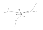
そこで、道糸2に浮きが2つ設けられる釣法が提案された。図13は、従来の浮きが2つ設けられた釣法(一般に「二段浮き釣法」と称される。)を模式的に示す図である。同図が示すように、道糸2には水中浮きと称される潜行浮き12と、当たり浮きと称される海面6に浮く浮き13とが装着されている(例えば、非特許文献1参照)。この場合、速い潮流が矢印11の方向に流れたときには、潜行浮き12が海中に潜行して仕掛け1を釣人の所望の位置へ運び、一方、浮き13は海面6に止まって、魚のヒットを釣人に知らせる。この釣法によれば、釣人に熟練が要請されず、釣人は、比較的簡単に釣りを行うことができる。
Therefore, a fishing method in which the
しかしながら、前述のように、海上の状況は刻々変化するものであるから、このような二段浮き釣法が適する状況が変化し、潮流が遅く波も小さくなり、いわゆる凪状態となる場合もある。そのような状況に変化した場合は、二段浮き釣法はむしろ適さず、図9に示された通常の釣法が適する。これに対応するために、釣人は、仕掛け全体を作り直す必要があり、この作業は非常に繁雑である。 However, as mentioned above, the situation at sea changes from moment to moment, so the situation suitable for such a two-stage floating fishing method changes, the tide is slow and the waves become smaller, so-called dredging may occur. . When changing to such a situation, the two-stage floating fishing method is rather not suitable, and the normal fishing method shown in FIG. 9 is suitable. In order to cope with this, the angler has to recreate the whole device, which is very complicated.
そこで、本発明の目的は、仕掛けの態様を簡単且つ迅速に変更し、釣人が海上の状況の変化に瞬時に対応することができる釣用浮きを提供することである。 SUMMARY OF THE INVENTION An object of the present invention is to provide a fishing float that allows a fisherman to quickly and easily respond to changes in sea conditions by changing the mode of the device easily and quickly.
(1) 上記目的が達成されるため、本発明に係る釣用浮きは、釣糸が挿通される第1釣糸挿通孔が貫通形成され、比重が1.035以上に設定された本体と、釣糸が挿通される第2釣糸挿通孔が貫通形成され、比重が1.035以下に設定された分離体と、分離体を所定の保持力で保持することによって上記第1釣糸挿通孔の中心と第2釣糸挿通孔の中心とを一致させた状態で当該分離体を本体に合体させる保持機構とを備えたことを特徴とするものである。 (1) In order to achieve the above object, the fishing float according to the present invention includes a main body having a first fishing line insertion hole through which a fishing line is inserted and a specific gravity set to 1.035 or more, and a fishing line. A second fishing line insertion hole to be inserted is formed so as to penetrate the separator, and the specific gravity is set to 1.035 or less, and by holding the separator with a predetermined holding force, the center of the first fishing line insertion hole and the second And a holding mechanism for combining the separated body with the main body in a state where the center of the fishing line insertion hole is aligned.
この構成によれば、保持機構によって分離体が本体に所定の保持力で合体される。このとき、第1釣糸挿通孔と第2釣糸挿通孔とが連通され、単一の釣糸挿通孔が形成される。すなわち、分離体が本体に合体されたときは、単一の中通し浮きが構成される。本体及び分離体が上記の比重に設定されるから、当該分離体が本体に合体された中通し浮きは、海中で所定の浮力を有する。一方、釣人は、所要時において、上記保持力に抗して分離体を引っ張ることによって分離体を本体から離脱させることができる。これにより、本体は、上記比重であることから水中浮きとして機能し、分離体は、上記比重であることから海面に浮く当たり浮きとして機能し得る。また、釣人は、さらに必要であれば、保持機構によって分離体を本体に合体させることができる。 According to this configuration, the separator is united with the main body by the holding mechanism with a predetermined holding force. At this time, the first fishing line insertion hole and the second fishing line insertion hole are communicated to form a single fishing line insertion hole. That is, when the separator is united with the main body, a single through float is formed. Since the main body and the separated body are set to the above specific gravity, the through-bore combined with the separated body combined with the main body has a predetermined buoyancy in the sea. On the other hand, when required, the angler can pull the separator away from the main body by pulling the separator against the holding force. Thereby, the main body functions as floating in water because of the specific gravity, and the separator can function as floating when floating on the sea surface because of the specific gravity. Moreover, the angler can unite the separated body with the main body by the holding mechanism if necessary.
ここで、上記保持機構は、本体に立設された保持棒と、分離体に設けられ、保持棒と螺合する螺合凹部とを有して構成される。この構成では、本体側に設けられた保持棒に分離体がねじ込まれるだけで、分離体が簡単に本体に保持され、また、簡単に本体から分離される。 Here, the holding mechanism is configured to include a holding bar erected on the main body and a screwing recess provided on the separating body and screwed to the holding bar. In this configuration, the separation body is simply held by the main body and is easily separated from the main body simply by screwing the separation body into the holding rod provided on the main body side.
特に、上記保持棒としては、先端部外周面に雄ねじが形成され且つ上記第1釣糸挿通孔を構成する筒状部材が採用され、上記螺合凹部は、上記第2釣糸挿通孔に形成されたねじ孔により構成され得る。この場合では、筒状部材が本体に貫通配置されることによって保持棒が形成されると同時に第1釣糸挿通孔が形成されるので、第1釣糸挿通孔を形成するための特別の加工が不要となる。しかも、第2釣糸挿通孔の一部によって、保持棒が螺合されるねじ孔が構成されるから、保持棒と螺合するための当該ねじ孔を正確に位置決めする作業が不要となる。すなわち、この第2釣糸挿通孔に上記ねじ孔が設けられることによって、当該ねじ孔の位置は、自動的に上記保持棒の位置と一致する。 In particular, as the holding rod, a cylindrical member having a male screw formed on the outer peripheral surface of the tip and forming the first fishing line insertion hole is employed, and the screwing recess is formed in the second fishing line insertion hole. It can be constituted by a screw hole. In this case, since the holding rod is formed at the same time as the cylindrical member is disposed through the main body, the first fishing line insertion hole is formed, so that no special processing for forming the first fishing line insertion hole is required. It becomes. Moreover, since a screw hole into which the holding rod is screwed is constituted by a part of the second fishing line insertion hole, an operation of accurately positioning the screw hole for screwing with the holding rod becomes unnecessary. That is, by providing the screw hole in the second fishing line insertion hole, the position of the screw hole automatically matches the position of the holding rod.
(2) また、上記保持機構は、本体に立設され、先端部が略球形に形成された保持棒と、分離体に設けられ、保持棒の先端部と嵌合する嵌合凹部とを有し、当該嵌合凹部は保持棒の先端部が挿脱される開口を有し、当該開口の内径寸法が上記先端部の外径寸法よりも小さく設定されることにより構成され得る。この構成では、本体側に設けられた保持棒が分離体の嵌合凹部に押し込まれるだけで、分離体が簡単に本体に保持され、また、分離体が保持棒から引き抜かれるだけで、簡単に本体から分離される。 (2) Further, the holding mechanism has a holding rod that is erected on the main body and has a tip that is substantially spherical, and a fitting recess that is provided on the separating body and engages with the tip of the holding rod. The fitting recess has an opening through which the distal end portion of the holding rod is inserted and removed, and the inner diameter dimension of the opening is set smaller than the outer diameter dimension of the distal end portion. In this configuration, the holding bar provided on the main body side is simply pushed into the fitting recess of the separating body, the separating body is easily held by the main body, and the separating body is simply pulled out from the holding rod, Separated from the body.
ここで、上記保持棒は、上記第1釣糸挿通孔を構成する筒状に形成され、上記嵌合凹部は、上記第2釣糸挿通孔の端部の内壁面形状が略球形に形成されることによって形成され得る。この場合では、保持棒が本体に貫通配置されることによって、当該保持棒が筒状に形成されていることから同時に第1釣糸挿通孔が形成される。したがって、第1釣糸挿通孔を形成するための特別の加工が不要となる。しかも、第2釣糸挿通孔の一部によって嵌合凹部が構成されるから、保持棒と嵌合するために当該嵌合凹部を正確に位置決めする作業が不要となる。すなわち、この第2釣糸挿通孔に上記嵌合凹部が設けられることによって、当該嵌合凹部の位置は、自動的に上記保持棒の位置と一致する。 Here, the holding rod is formed in a cylindrical shape that constitutes the first fishing line insertion hole, and the fitting recess is formed so that the inner wall surface shape of the end portion of the second fishing line insertion hole is substantially spherical. Can be formed. In this case, the first fishing line insertion hole is formed at the same time since the holding rod is formed in a cylindrical shape by penetrating the holding rod into the main body. Therefore, special processing for forming the first fishing line insertion hole is not required. And since a fitting recessed part is comprised by a part of 2nd fishing line penetration hole, the operation | work which positions the said fitting recessed part correctly in order to fit with a holding rod becomes unnecessary. That is, by providing the fitting recess in the second fishing line insertion hole, the position of the fitting recess automatically matches the position of the holding rod.
特に、上記保持棒の先端部は、外径寸法が弾性的に拡縮可能なように軸方向に沿ってスリットが形成されているのが好ましい。これにより、保持棒の先端部が嵌合凹部に嵌め込まれる際に、当該先端部の外径寸法は、嵌合凹部の開口の内径寸法に対応して弾性的に小さくなる。したがって、保持棒に分離体が容易に嵌め込まれるという利点がある。 In particular, it is preferable that the tip of the holding rod has a slit formed along the axial direction so that the outer diameter can be expanded and contracted elastically. Thereby, when the front-end | tip part of a holding rod is engage | inserted by a fitting recessed part, the outer diameter dimension of the said front-end | tip part becomes elastically small corresponding to the internal diameter dimension of the opening of a fitting recessed part. Therefore, there is an advantage that the separator is easily fitted into the holding rod.
(3) さらに、上記保持機構は、本体に設けられ、開口を有する分離体収容部と、当該開口の周縁部から分離体収容部の内壁面に沿って形成された雌ねじ部と、分離体の外周面に形成された雄ねじ部とを備えて構成され得る。この構成では、分離体は、本体の分離体収容部に直接ねじ込まれることにより、本体に簡単に保持される。 (3) Further, the holding mechanism is provided in the main body and has a separator housing portion having an opening, a female screw portion formed along the inner wall surface of the separator housing portion from a peripheral portion of the opening, And an external thread portion formed on the outer peripheral surface. In this configuration, the separator is easily held by the main body by being screwed directly into the main body separator housing portion.
(4) また、上記保持機構は、本体に設けられ、開口を有するた分離体収容部と、当該開口の周縁部から分離体収容部の内壁面に沿って形成された略L字状の係合溝と、分離体の外周面に突設され、係合溝と係合する係合爪とを備えて構成され得る。この構成では、分離体は、係合爪が本体の係合溝に挿入され、当該係合溝に沿ってスライドされることによって、本体に保持される。しかも、係合溝が略L字状に形成されているから、上記係合爪と係合溝との係合及び係合解除は、きわめて簡単に行われる。 (4) Further, the holding mechanism is provided in the main body, and has a separator housing portion having an opening, and a substantially L-shaped hook formed along the inner wall surface of the separator housing portion from the peripheral portion of the opening. It can be configured to include a mating groove and an engaging claw that projects from the outer peripheral surface of the separator and engages with the engaging groove. In this configuration, the separator is held by the main body by inserting the engaging claw into the engaging groove of the main body and sliding along the engaging groove. In addition, since the engagement groove is formed in a substantially L shape, the engagement and disengagement between the engagement claw and the engagement groove can be performed very easily.
以上のように本発明によれば、分離体が本体に合体されることによって単一の中通し浮きが構成され、所要時には、分離体が本体から離脱されるので、釣人が単一の中通し浮きとして使用しているときであっても、分離体を本体から分離させることによって、本体を水中浮きとして使用し、分離体を当たり浮きとして使用することが可能である。したがって、釣人は、海上の状況の変化に瞬時に対応して仕掛けの態様を簡単且つ迅速に変更することができる。 As described above, according to the present invention, when the separator is united with the main body, a single through float is formed, and when necessary, the separator is detached from the main body. Even when it is used as a float, by separating the separator from the main body, it is possible to use the main body as a float in water and use the separator as a float. Therefore, the angler can change the mode of the device easily and quickly in response to a change in the situation at sea.
以下、適宜図面が参照されつつ、好ましい実施形態に基づいて本発明が詳細に説明される。 Hereinafter, the present invention will be described in detail based on preferred embodiments with appropriate reference to the drawings.
<第1の実施形態>
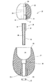
図1は、本発明の第1の実施形態に係る釣用浮き20の正面図であり、図2は、一部断面分解正面図である。
<First Embodiment>
FIG. 1 is a front view of a
この釣用浮き20は、本体21と分離体22とを有し、分離体22は、後に詳述される保持機構30を介して本体21に着脱されるようになっている。すなわち、本実施形態に係る釣用浮き20は、本体21と分離体22とが合体された状態(図1に示す状態)で単一の中通し浮きとして構成され、本体21と分離体22とが分離された状態では、本体21が水中浮きとして使用され、一方、分離体22が当たり浮きとして使用され得るものであり、本体21と分離体22とは、ワンタッチで合体又は分離がなされるようになっている。
The
本体21は、木材、樹脂等により構成されており、外形形状が略紡錘形ないし卵形に形成されている。なお、本実施形態では、本体21が卵形に形成されているが、これに限定されるものではなく、他の種々の外形形状に形成されていてもよいことは勿論である。また、本体21の下端部には錘23が埋設されている。この錘23は、例えば鉛等の金属により構成されており、その下端面は、本体21の外周面の一部を形成している。
The
本体21には、分離体22が収容される収容部24と、収容部24に連通する貫通孔25(第1釣糸挿通孔)とが設けられている。収容部24は、本体21の上面26から下方へ向かって形成されており、その内壁面形状は、略球形に形成されている。収容部24の仮想中心軸は、本体21の仮想中心軸と一致している。この収容部24の内径寸法は、分離体22の外形寸法に対応されており、分離体22は、図1が示すように、収容部24に隙間なく嵌め込まれるようになっている。
The
また、貫通孔25は、釣用浮き20が中通し浮きとして使用される際に釣糸が挿通される部分であり、収容部24の底面中央部から下方に向かって設けられている。すなわち、貫通孔25は、その仮想中心軸が本体21の上記仮想中心軸と一致しており、したがって、本体21の中心を上下方向に沿って延び、且つ収容部24に連通している。なお、本実施形態では、貫通孔25の上端部36は、若干拡径されており、貫通孔25に段部が形成されている。この段部による作用効果については後述される。
Further, the through
分離体22は、本体21と同様に木材、樹脂等により構成されており、外形形状は、略樽形に形成されている。なお、分離体22についても、略樽型に限定されるものではなく、他の種々の外形形状に形成されていてもよいことは勿論である。また、分離体22の下端部には錘27が埋設されている。この錘27は、本体21に設けられた錘と同様に、例えば鉛等の金属により構成されており、その下端面は、分離体22の外周面(下面)の一部を形成している。
The
分離体22には、その仮想中心軸に沿って貫通孔28(第2釣糸挿通孔)が設けられている。貫通孔28は、釣用浮き20が中通し浮きとして使用される際に釣糸が挿通される部分である。また、この貫通孔28の下端部には、螺合凹部31が設けられている。この螺合凹部31は、貫通孔28の下端部が拡径されることにより構成されており、その内周面には、雌ねじ32が形成されている。
The separating
さらに、本実施形態では、上記貫通孔28の上端部にスリーブ29が嵌め込まれている。このスリーブ29は、円筒状に形成されており、樹脂や金属等により構成される。このスリーブ29が設けられることによって、釣糸が貫通孔28に非常に滑らかに挿通される。もっとも、このスリーブ29は、省略されてもよいことは勿論である。
Furthermore, in the present embodiment, a
保持機構30は、保持棒33と、上記螺合凹部31とにより構成される。保持棒33は、円筒状の部材であり、樹脂や金属等により構成されている。この保持棒33の先端部35は、拡径されており、当該先端部35に雄ねじ34が形成されている。この雄ねじ34は、上記螺合凹部31に設けられた雌ねじ32と螺合するようになっている。保持棒33の外径寸法は、本体21に設けられた貫通孔25の内径寸法に対応されており、したがって、保持棒33は、上記貫通孔25に隙間なく挿入される。このように、保持棒33が貫通孔25に挿入されることにより、保持棒33が円筒状に形成されていることから、保持棒33の軸方向に沿って形成される孔38は、上記釣糸が挿通される部分を構成することになる。
The holding
このとき、貫通孔25の上端部36が前述のように拡径されることにより段部が形成されているが、この上端部36の内径寸法は、保持棒33の先端部35の外径寸法に対応されている。したがって、保持棒33が上記貫通孔25に上方から挿通された状態では、保持棒33の先端部35が上記貫通孔25の上端部36によって形成される段部に当接する。なお、本実施形態では、保持棒33の下端部に固定リング37が設けられている。この固定リング37は、樹脂や金属等からなる環状の部材であって、その内径寸法は保持棒33の外径寸法に対応され、その外径寸法は、上記貫通孔25の内径寸法よりも大きくなるように設定されている。そして、保持棒33が上方から上記貫通孔25に挿通され、当該保持棒33の下端部に固定リング37が固定されることによって、本体21に立設された状態となる。すなわち、保持棒33は、本体21の中心を貫通した状態で配置され、上記収容部24に突出する。
At this time, a step portion is formed by expanding the
このように本体21に錘23、保持棒33及び固定リング37が設けられることによって、本体21の比重は、1.035以上に設定される。具体的には、本体21の比重は、1.03〜1.15の範囲で設定され、好ましくは、1.035〜1.05の範囲で設定され得る。また、分離体22は、上記錘27及びスリーブ29が設けられることによって、比重が1.035以下に設定される。具体的には、分離体22の比重は、0.75〜1.035の範囲で設定され、好ましくは、0.85〜1.035の範囲で設定され得る。
Thus, by providing the
分離体22は、前述のように本体21の上記収容部24に嵌め込まれるものであるが、このとき分離体22の螺合凹部31に保持棒33が螺合される。つまり、分離体22は、収容部24に嵌め込まれる際に、保持棒33の先端部にねじ込まれる。これにより、分離体22が本体21に保持固定されると共に、保持棒33の孔38の中心と分離体22の貫通孔25の中心とが一致され、釣用浮き20の中心を上下方向(軸方向)に沿って貫通する単一の釣糸挿通孔39(図1参照)が形成される。
As described above, the separating
このように本実施形態に係る釣用浮き20では、保持機構30によって分離体22が本体21と合体される。この状態では、本体21の貫通孔25と分離体22の貫通孔28とが連通され、単一の釣糸挿通孔39(図1参照)が形成される。すなわち、図3が示すように、分離体22が本体21に合体されて釣用浮き20が構成される。このとき、本体21及び分離体22の比重が前述のように設定されるから、当該釣用浮き20は、海中で所定の浮力を有する中通し浮きとして構成され、通常の海面Lに浮かぶ浮きとして使用される。
Thus, in the
一方、図4が示すように、釣人は、所要時(例えば潮流が速い場合等)においては、分離体22を本体21から離脱させることによって、釣用浮き20をいわゆる二段浮きとして使用することができ、本体21を水中浮きとして使用し、分離体22を当たり浮きとして使用することができる。さらに、釣人は、必要であれば、再び分離体22を本体21に合体させて釣用浮き20を単一の中通し浮きとして使用することができる。
On the other hand, as shown in FIG. 4, the angler uses the
よって、本実施形態に係る釣用浮き20では、釣人の所望時に単一の中通し浮きとして使用することもでき、また二段浮きとして使用することもできるので、釣人は、海上の状況の変化に瞬時に対応して仕掛けの態様を簡単且つ迅速に変更することができる。
Therefore, in the
特に、本実施形態では、上記保持機構30が本体21側に設けられた保持棒33と、分離体22側に設けられた螺合凹部31とにより構成されるので(図2参照)、釣人は、分離体22を本体21にねじ込むという簡単な作業により、両者を合体させることができると共に、同様の作業によって、両者を簡単に分離することができる。したがって、釣人は、海上の状況の変化に一層迅速に対応して仕掛けの態様を変更することができる。
In particular, in the present embodiment, since the holding
さらに、本実施形態では、筒状の保持棒33が本体21に貫通配置されることによって当該保持棒33が本体21に立設されると共に、釣糸が挿通される貫通孔28が構成される。したがって、分離体22を保持固定するために保持棒33が別途設けられたとしても、特別に釣糸が挿通される孔の加工が不要であるという利点がある。
Furthermore, in this embodiment, the
<第2の実施形態>
次に、本発明の第2の実施形態について説明される。
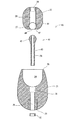
図5は、本発明の第2の実施形態に係る釣用浮き40の分解断面図である。
<Second Embodiment>
Next, a second embodiment of the present invention will be described.
FIG. 5 is an exploded cross-sectional view of a
本実施形態に係る釣用浮き40が上記第1の実施形態に係る釣用浮き20と異なるところは、上記釣用浮き20では、保持機構30は、雄ねじ34が形成された保持棒33と、分離体22に設けられた螺合凹部31とにより構成されていたのに対し、本実施形態に係る釣用浮き40では、保持機構41は、先端部42が略球形に形成された保持棒43と、分離体22に設けられた嵌合凹部44とにより構成されている点である。つまり、保持棒43の先端部42に分離体22が嵌め込まれることによって、本体21と分離体22とが合体されるようになっている。なお、その他の構成については、上記第1の実施形態に係る釣用浮き20と同様である。
The
図6は、保持棒43の拡大斜視図である。
同図が示すように、保持棒43の先端部42は、外径が滑らからに拡大されており、これにより略球形に形成されている。なお、上記第1の実施形態に係る保持棒33と同様に、保持棒43は筒状に形成され、軸方向に沿って孔38が設けられている。また、この先端部42には、スリット45、46が形成されている。これらスリット45、46は、互いに直交して十字状に形成されており、これにより、当該先端部42の外径寸法は、弾性的に拡縮が可能となっている。
FIG. 6 is an enlarged perspective view of the holding
As shown in the figure, the
また、嵌合凹部44は、分離体22の貫通孔28の下端部に設けられており、その内壁面形状は、略球形に形成されている。この嵌合凹部44は、分離体22の下面47に開口48を有し、上記保持棒43の先端部42は、この開口48から嵌合凹部44に嵌め込まれるようになっている。
Moreover, the fitting recessed
本実施形態においても、保持棒43は、本体21の貫通孔25に上方から挿通され、固定リング37が装着されることによって本体21に立設される。このとき、保持棒43の先端部42は、収容部24内に突出する。釣人は、分離体22を収容部24に挿入し、保持棒43の先端部42を分離体22の嵌合凹部44に嵌め込むだけで、分離体22は、一定の保持力で本体21に固定される。また、釣人は、当該保持力に抗して分離体22を引っ張ることによって、分離体22を本体21から分離させることができる。したがって、釣用浮き40は、上記第1の実施形態に係る釣用浮き20と同様に、単一の中通し浮きとして使用することもでき、所要時には、分離体22を本体21から簡単に切り離して二段浮きとして使用することができる。
Also in the present embodiment, the holding
特に、本実施形態では、保持棒43の先端部42にスリット45、46が設けられているから、保持棒43が上記嵌合凹部44に嵌合する際には、保持棒43の先端部42が弾性的に縮径される。したがって、分離体22は、きわめて簡単に保持棒43と嵌合する。そして、分離体22の先端部42が嵌合凹部44内に嵌め込まれると、保持棒43の先端部が弾性的に拡径され、分離体22は、本体21側に一定の保持力で確実に保持される。なお、釣人は、再び分離体22を本体21から分離する場合には、分離体22を引っ張る作業を行うが、このとき、上記保持棒43の先端部42が弾性的に縮径されるので、分離体22を分離する作業も容易である。
In particular, in the present embodiment, since the
<第3の実施形態>
次に、本発明の第3の実施形態について説明される。
図7は、本発明の第3の実施形態に係る釣用浮き50の分解断面図である。
<Third Embodiment>
Next, a third embodiment of the present invention will be described.
FIG. 7 is an exploded cross-sectional view of a
本実施形態に係る釣用浮き50が上記第1の実施形態に係る釣用浮き20と異なるところは、保持機構51の構造であって、上記釣用浮き20では、保持棒33を介して分離体22が本体21に合体されていたのに対し、本実施形態に係る釣用浮き50では、分離体22が直接本体21にねじ込まれることによって両者が合体されるようになっている点である。なお、その他の構成については、上記第1の実施形態に係る釣用浮き20と同様であるが、特に本実施形態に係る釣用浮き50では、本体21の貫通孔25は真直に形成され、この貫通孔25にスリーブ52が装着されており、一方、分離体22の貫通孔28にもスリーブ53が装着されている。各スリーブ52、53が設けられることによって、釣糸は、スムーズに各貫通孔25、28に挿通される。
The
本体21の収容部24の内壁面には、雌ねじ54が形成されている。一方、分離体22の周面には、雄ねじ55が形成されている。釣人は、分離体22を把持し、雄ねじ55と本体21の雌ねじ54とを螺合させることによって、本体21と分離体22とを合体させることができる。このように、本実施形態では、分離体22が直接本体21にねじ込まれるから、本体21に対する分離体22の着脱作業がきわめて簡単であり、釣用浮き50は、単一の中通し浮きとしても、二段浮きとしてもより使い勝手の良いものとなる。
A
<第4の実施形態>
次に、本発明の第4の実施形態について説明される。
図8は、本発明の第4の実施形態に係る釣用浮き60の分解断面図である。
<Fourth Embodiment>
Next, a fourth embodiment of the present invention will be described.
FIG. 8 is an exploded sectional view of a
本実施形態に係る釣用浮き60が上記第1の実施形態に係る釣用浮き20と異なるところは、保持機構61の構造であって、上記釣用浮き20では、保持棒33を介して分離体22が本体21に合体されていたのに対し、本実施形態に係る釣用浮き60では、分離体22に形成された係合爪62が本体21に設けられた係合溝63に嵌め込まれることによって両者が合体されるようになっている点である。なお、その他の構成については、上記第1の実施形態に係る釣用浮き20と同様であるが、特に本実施形態に係る釣用浮き60では、上記第3の実施形態に係る釣用浮き50と同様に、本体21の貫通孔25は真直に形成され、この貫通孔25にスリーブ52が装着されており、一方、分離体22の貫通孔28にもスリーブ53が装着されている。
The
分離体22に設けられた係合爪62は、略円柱状に形成され、分離体22の周面から外側に向かって突設されている。係合爪62は、本実施形態では、分離体22の周面に周方向に対象に4カ所に設けられている。もっとも、係合爪62は、周方向に対象に2カ所に設けられていてもよいし、さらに多数設けられていてもよい。
The engaging
上記係合溝63は、略L字状に形成されている。具体的には、係合溝63は、本体21の上面26から収容部24の内壁面に沿って下方へ延び、その後収容部24の内壁面に沿って周方向に延びている。係合溝63の溝幅寸法は、上記係合爪62の外径寸法に対応されており、係合爪62は、係合溝63に隙間なく嵌め込まれるようになっている。したがって、係合爪62は、この係合溝63に挿入され、当該係合溝63に沿ってスライドされることによって、分離体22が本体21に係合保持される。なお、上記係合爪62及び係合溝63の形状は、上記の形状に限定されるものではなく、両者が隙間なく係合するために互いに同様の形状に形成されていればよい。
The
本実施形態では、釣人は、分離体22を把持して係合爪62を本体21の係合溝63に嵌め込み、当該係合溝63に沿って分離体22をスライドさせるだけで、簡単に分離体22を本体21に固定することができ、また、分離体22を本体21から取り外すことができる。このとき、係合爪62の外形寸法及び係合溝63の内形寸法が適当に設定されることによって、両者間に所定の摩擦力が生じ、これにより、分離体22が本体21に合体した状態で、釣人の意図しないときに両者が分離してしまうことが防止される。このように、本実施形態に係る釣用浮き60においても、単一の中通し浮きとしても、二段浮きとしてもより使い勝手の良いものとなる。
In the present embodiment, the angler simply separates the
本発明は、釣り、特に海での浮き釣りに使用される浮きに適用され得る。 The present invention can be applied to floats used for fishing, particularly floating fishing at sea.
20・・・釣用浮き
21・・・本体
22・・・分離体
23・・・錘
24・・・収容部
25・・・貫通孔
27・・・錘
28・・・貫通孔
30・・・保持機構
31・・・螺合凹部
32・・・雌ねじ
33・・・保持棒
34・・・雄ねじ
38・・・孔
39・・・釣糸挿通孔
40・・・釣用浮き
41・・・保持機構
42・・・先端部
43・・・保持棒
44・・・嵌合凹部
45・・・スリット
46・・・スリット
47・・・下面
48・・・開口
50・・・釣用浮き
51・・・保持機構
52・・・スリーブ
53・・・スリーブ
54・・・雌ねじ
55・・・雄ねじ
60・・・釣用浮き
61・・・保持機構
62・・・係合爪
63・・・係合溝
DESCRIPTION OF
Claims (8)
釣糸が挿通される第2釣糸挿通孔が貫通形成され、比重が1.035以下に設定された分離体と、
分離体を所定の保持力で保持することによって上記第1釣糸挿通孔の中心と第2釣糸挿通孔の中心とを一致させた状態で当該分離体を本体に合体させる保持機構とを備えた釣用浮き。 A main body in which a first fishing line insertion hole through which a fishing line is inserted is formed to have a specific gravity of 1.035 or more;
A second fishing line insertion hole through which a fishing line is inserted is formed so as to penetrate, and a specific gravity is set to 1.035 or less;
A fishing device comprising a holding mechanism for holding the separated body with a predetermined holding force so that the center of the first fishing line insertion hole and the center of the second fishing line insertion hole are aligned with each other. Floating.
本体に立設された保持棒と、
分離体に設けられ、保持棒と螺合する螺合凹部とを有する釣用浮き。 The holding mechanism is
A holding rod erected on the main body,
A fishing float provided on the separating body and having a threaded recess that is threadedly engaged with a holding rod.
上記螺合凹部は、上記第2釣糸挿通孔に形成されたねじ孔からなる請求項2に記載の釣用浮き。 The holding rod is formed of a cylindrical member having a male thread formed on the outer peripheral surface of the tip and constituting the first fishing line insertion hole,
The fishing float according to claim 2, wherein the screw recess is a screw hole formed in the second fishing line insertion hole.
本体に立設され、先端部が略球形に形成された保持棒と、
分離体に設けられ、保持棒の先端部と嵌合する嵌合凹部とを有し、
当該嵌合凹部は保持棒の先端部が挿脱される開口を有し、当該開口の内径寸法が上記先端部の外径寸法よりも小さく設定されている請求項1に記載の釣用浮き。 The holding mechanism is
A holding rod which is erected on the main body and has a substantially spherical tip.
Provided in the separator, and having a fitting recess to be fitted to the tip of the holding rod;
2. The fishing float according to claim 1, wherein the fitting recess has an opening through which a tip of the holding rod is inserted and removed, and an inner diameter of the opening is set smaller than an outer diameter of the tip.
上記嵌合凹部は、上記第2釣糸挿通孔の端部の内壁面形状が略球形に形成されることによって形成されている請求項4に記載の釣用浮き。 The holding rod is formed in a cylindrical shape constituting the first fishing line insertion hole,
The fishing float according to claim 4, wherein the fitting recess is formed by forming an inner wall surface shape of an end portion of the second fishing line insertion hole into a substantially spherical shape.
本体に設けられ、開口を有する分離体収容部と、
当該開口の周縁部から分離体収容部の内壁面に沿って形成された雌ねじ部と、
分離体の外周面に形成された雄ねじ部とを備えている請求項1に記載の釣用浮き。 The holding mechanism is
A separator housing part provided in the main body and having an opening;
An internal thread portion formed along the inner wall surface of the separator housing portion from the peripheral portion of the opening;
The fishing float according to claim 1, further comprising a male thread portion formed on the outer peripheral surface of the separator.
本体に設けられ、開口を有するた分離体収容部と、
当該開口の周縁部から分離体収容部の内壁面に沿って形成された略L字状の係合溝と、
分離体の外周面に突設され、係合溝と係合する係合爪とを備えている請求項1に記載の釣用浮き。
The holding mechanism is
A separator housing portion provided in the main body and having an opening;
A substantially L-shaped engagement groove formed along the inner wall surface of the separator housing portion from the peripheral edge of the opening;
The fishing float according to claim 1, further comprising an engaging claw protruding from an outer peripheral surface of the separator and engaging with the engaging groove.
Priority Applications (4)
| Application Number | Priority Date | Filing Date | Title |
|---|---|---|---|
| JP2003318954A JP2005080614A (en) | 2003-09-10 | 2003-09-10 | Float for fishing |
| TW093126059A TW200513181A (en) | 2003-09-10 | 2004-08-30 | Float for fishing |
| KR1020040071865A KR20050026871A (en) | 2003-09-10 | 2004-09-08 | Fishing float |
| CNB2004100737508A CN100508744C (en) | 2003-09-10 | 2004-09-09 | Float for fishing |
Applications Claiming Priority (1)
| Application Number | Priority Date | Filing Date | Title |
|---|---|---|---|
| JP2003318954A JP2005080614A (en) | 2003-09-10 | 2003-09-10 | Float for fishing |
Publications (1)
| Publication Number | Publication Date |
|---|---|
| JP2005080614A true JP2005080614A (en) | 2005-03-31 |
Family
ID=34418085
Family Applications (1)
| Application Number | Title | Priority Date | Filing Date |
|---|---|---|---|
| JP2003318954A Pending JP2005080614A (en) | 2003-09-10 | 2003-09-10 | Float for fishing |
Country Status (4)
| Country | Link |
|---|---|
| JP (1) | JP2005080614A (en) |
| KR (1) | KR20050026871A (en) |
| CN (1) | CN100508744C (en) |
| TW (1) | TW200513181A (en) |
Cited By (5)
| Publication number | Priority date | Publication date | Assignee | Title |
|---|---|---|---|---|
| US7797877B1 (en) * | 2007-02-15 | 2010-09-21 | Gary Bennis | Fixed and slip fishing apparatus for bobbers |
| US20130145676A1 (en) * | 2007-02-15 | 2013-06-13 | Gary Bennis | Slip Bobber Rig |
| JP5813271B1 (en) * | 2015-06-29 | 2015-11-17 | 横山 武志 | Floating |
| CN106818665A (en) * | 2016-12-21 | 2017-06-13 | 麦敢连 | A kind of cross is cursory |
| US20190216071A1 (en) * | 2007-02-15 | 2019-07-18 | Gary Bennis | Stem guides and replaceable cartridges |
Families Citing this family (1)
| Publication number | Priority date | Publication date | Assignee | Title |
|---|---|---|---|---|
| KR101242211B1 (en) * | 2011-06-18 | 2013-03-11 | 이원도 | A fishing electrical float to be separated |
-
2003
- 2003-09-10 JP JP2003318954A patent/JP2005080614A/en active Pending
-
2004
- 2004-08-30 TW TW093126059A patent/TW200513181A/en not_active IP Right Cessation
- 2004-09-08 KR KR1020040071865A patent/KR20050026871A/en not_active Application Discontinuation
- 2004-09-09 CN CNB2004100737508A patent/CN100508744C/en not_active Expired - Fee Related
Cited By (11)
| Publication number | Priority date | Publication date | Assignee | Title |
|---|---|---|---|---|
| US7797877B1 (en) * | 2007-02-15 | 2010-09-21 | Gary Bennis | Fixed and slip fishing apparatus for bobbers |
| US20130145676A1 (en) * | 2007-02-15 | 2013-06-13 | Gary Bennis | Slip Bobber Rig |
| US20140033599A1 (en) * | 2007-02-15 | 2014-02-06 | Gary Bennis | Stem guides and replaceable cartridges |
| US8756855B2 (en) * | 2007-02-15 | 2014-06-24 | Gary Bennis | Slip bobber rig |
| US8819986B2 (en) * | 2007-02-15 | 2014-09-02 | Gary Bennis | Stem guides and replaceable cartridges |
| US10058084B2 (en) * | 2007-02-15 | 2018-08-28 | Gary Bennis | Stem guides and replaceable cartridges |
| US20190216071A1 (en) * | 2007-02-15 | 2019-07-18 | Gary Bennis | Stem guides and replaceable cartridges |
| US10813348B2 (en) * | 2007-02-15 | 2020-10-27 | Gary Bennis | Stem guides and replaceable cartridges |
| US11317616B2 (en) * | 2007-02-15 | 2022-05-03 | Gary Bennis | Stem guides and replaceable cartridges |
| JP5813271B1 (en) * | 2015-06-29 | 2015-11-17 | 横山 武志 | Floating |
| CN106818665A (en) * | 2016-12-21 | 2017-06-13 | 麦敢连 | A kind of cross is cursory |
Also Published As
| Publication number | Publication date |
|---|---|
| KR20050026871A (en) | 2005-03-16 |
| CN100508744C (en) | 2009-07-08 |
| TW200513181A (en) | 2005-04-16 |
| CN1618283A (en) | 2005-05-25 |
| TWI318560B (en) | 2009-12-21 |
Similar Documents
| Publication | Publication Date | Title |
|---|---|---|
| US20070107295A1 (en) | Artificial fishing lure with adjustable weight | |
| JP2005080614A (en) | Float for fishing | |
| US20100205844A1 (en) | Devices and Methods for Recovering Articles Inadvertently Submerged in a Body of Water | |
| JP2010054020A (en) | Lock ring for pipe fitting and pipe fitting | |
| US20210120795A1 (en) | Fishing tackle and method of use thereof | |
| JP2008000110A (en) | Engaging tool for fishing | |
| JP2003092961A (en) | Variable buoyancy linterline float using multifunctional auxiliary pipe | |
| KR200476992Y1 (en) | fine buoyancy control sinker for Fishing tackle | |
| KR20160003565U (en) | Fishing Sinker | |
| KR200283407Y1 (en) | Float | |
| JPH0741352Y2 (en) | Through | |
| JP4437397B2 (en) | Fishing float | |
| KR200260401Y1 (en) | A combination fixed and flow float | |
| JP6695623B2 (en) | Uki for fishing | |
| JP2005210946A (en) | Float for drift lining | |
| KR200377267Y1 (en) | a fishing float | |
| JP5700281B2 (en) | Bat and fishing rod | |
| KR20220002540U (en) | Fishing lure assembly | |
| JP2006280355A (en) | Attachable and detachable guide for fishing rod and shaking-out type fishing rod | |
| JP2008187925A (en) | Float for fishing | |
| JP2002223683A (en) | Fishing float set | |
| KR200306620Y1 (en) | A float for fishing | |
| JP2001103892A (en) | Internally threaded rod float | |
| KR200274661Y1 (en) | A fish spear for catching fishes | |
| KR200207786Y1 (en) | The connecter for a fishing float |
Legal Events
| Date | Code | Title | Description |
|---|---|---|---|
| A621 | Written request for application examination |
Free format text: JAPANESE INTERMEDIATE CODE: A621 Effective date: 20060822 |
|
| A977 | Report on retrieval |
Free format text: JAPANESE INTERMEDIATE CODE: A971007 Effective date: 20080619 |
|
| A131 | Notification of reasons for refusal |
Free format text: JAPANESE INTERMEDIATE CODE: A131 Effective date: 20080624 |
|
| A521 | Written amendment |
Free format text: JAPANESE INTERMEDIATE CODE: A523 Effective date: 20080811 |
|
| A02 | Decision of refusal |
Free format text: JAPANESE INTERMEDIATE CODE: A02 Effective date: 20090428 |