JP2005076502A - Internal combustion engine - Google Patents
Internal combustion engine Download PDFInfo
- Publication number
- JP2005076502A JP2005076502A JP2003306690A JP2003306690A JP2005076502A JP 2005076502 A JP2005076502 A JP 2005076502A JP 2003306690 A JP2003306690 A JP 2003306690A JP 2003306690 A JP2003306690 A JP 2003306690A JP 2005076502 A JP2005076502 A JP 2005076502A
- Authority
- JP
- Japan
- Prior art keywords
- exhaust gas
- amount
- recirculation
- egr
- passage
- Prior art date
- Legal status (The legal status is an assumption and is not a legal conclusion. Google has not performed a legal analysis and makes no representation as to the accuracy of the status listed.)
- Pending
Links
Images


Classifications
-
- F—MECHANICAL ENGINEERING; LIGHTING; HEATING; WEAPONS; BLASTING
- F02—COMBUSTION ENGINES; HOT-GAS OR COMBUSTION-PRODUCT ENGINE PLANTS
- F02M—SUPPLYING COMBUSTION ENGINES IN GENERAL WITH COMBUSTIBLE MIXTURES OR CONSTITUENTS THEREOF
- F02M26/00—Engine-pertinent apparatus for adding exhaust gases to combustion-air, main fuel or fuel-air mixture, e.g. by exhaust gas recirculation [EGR] systems
- F02M26/02—EGR systems specially adapted for supercharged engines
- F02M26/04—EGR systems specially adapted for supercharged engines with a single turbocharger
- F02M26/07—Mixed pressure loops, i.e. wherein recirculated exhaust gas is either taken out upstream of the turbine and reintroduced upstream of the compressor, or is taken out downstream of the turbine and reintroduced downstream of the compressor
-
- F—MECHANICAL ENGINEERING; LIGHTING; HEATING; WEAPONS; BLASTING
- F02—COMBUSTION ENGINES; HOT-GAS OR COMBUSTION-PRODUCT ENGINE PLANTS
- F02M—SUPPLYING COMBUSTION ENGINES IN GENERAL WITH COMBUSTIBLE MIXTURES OR CONSTITUENTS THEREOF
- F02M26/00—Engine-pertinent apparatus for adding exhaust gases to combustion-air, main fuel or fuel-air mixture, e.g. by exhaust gas recirculation [EGR] systems
- F02M26/13—Arrangement or layout of EGR passages, e.g. in relation to specific engine parts or for incorporation of accessories
- F02M26/34—Arrangement or layout of EGR passages, e.g. in relation to specific engine parts or for incorporation of accessories with compressors, turbines or the like in the recirculation passage
-
- F—MECHANICAL ENGINEERING; LIGHTING; HEATING; WEAPONS; BLASTING
- F02—COMBUSTION ENGINES; HOT-GAS OR COMBUSTION-PRODUCT ENGINE PLANTS
- F02M—SUPPLYING COMBUSTION ENGINES IN GENERAL WITH COMBUSTIBLE MIXTURES OR CONSTITUENTS THEREOF
- F02M26/00—Engine-pertinent apparatus for adding exhaust gases to combustion-air, main fuel or fuel-air mixture, e.g. by exhaust gas recirculation [EGR] systems
- F02M26/13—Arrangement or layout of EGR passages, e.g. in relation to specific engine parts or for incorporation of accessories
- F02M26/22—Arrangement or layout of EGR passages, e.g. in relation to specific engine parts or for incorporation of accessories with coolers in the recirculation passage
- F02M26/23—Layout, e.g. schematics
- F02M26/28—Layout, e.g. schematics with liquid-cooled heat exchangers
Abstract
Description
本発明は、内燃機関に関する。 The present invention relates to an internal combustion engine.
従来より内燃機関、例えばディーゼル機関においてはNOxの発生を抑制するために機関排気通路と機関吸気通路とを排気ガス再循環(以下、EGRと称す)通路により連結し、このEGR通路を介して排気ガス、即ちEGRガスを機関吸気通路内に再循環させるようにしている。この場合、EGRガスは比較的比熱が高く、従って多量の熱を吸収することができるので、EGRガス量を増大するほど、即ちEGR率(EGRガス量/(EGRガス量+吸入空気量))を増大するほど燃焼室内における燃焼温度が低下する。燃焼温度が低下するとNOxの発生量が低下し、従ってEGR率を増大すればするほどNOxの発生量は低下することになる。 2. Description of the Related Art Conventionally, in an internal combustion engine, for example, a diesel engine, an engine exhaust passage and an engine intake passage are connected by an exhaust gas recirculation (hereinafter referred to as EGR) passage in order to suppress the generation of NOx, and the exhaust gas is exhausted through the EGR passage. Gas, that is, EGR gas is recirculated into the engine intake passage. In this case, since the EGR gas has a relatively high specific heat and can absorb a large amount of heat, the EGR gas amount increases, that is, the EGR rate (EGR gas amount / (EGR gas amount + intake air amount)). As the value increases, the combustion temperature in the combustion chamber decreases. As the combustion temperature decreases, the amount of NOx generated decreases, and as the EGR rate increases, the amount of NOx generated decreases.
このように従来よりEGR率を増大すればNOxの発生量を低下しうることはわかっている。しかしながらEGR率を増大させていくとEGR率が或る限度を越えたときに煤の発生量、即ちスモークが急激に増大し始める。この点に関し従来より、それ以上EGR率を増大すればスモークが限りなく増大していくものと考えられており、従ってスモークが急激に増大し始めるEGR率がEGR率の最大許容限界であると考えられている。 Thus, it has been known that the amount of NOx generated can be reduced if the EGR rate is increased. However, when the EGR rate is increased, when the EGR rate exceeds a certain limit, the generation amount of soot, that is, the smoke starts to increase rapidly. With respect to this point, it is conventionally considered that if the EGR rate is further increased, the smoke will increase as much as possible. Therefore, the EGR rate at which the smoke starts to increase rapidly is considered to be the maximum allowable limit of the EGR rate. It has been.
従って従来よりEGR率はこの最大許容限界を越えない範囲内に定められている。このEGR率の最大許容限界は機関の形式や燃料によってかなり異なるがおおよそ30パーセントから50パーセントである。従って従来のディーゼル機関ではEGR率は最大でも30パーセントから50パーセント程度に抑えられている。 Therefore, the EGR rate is conventionally determined within a range not exceeding the maximum allowable limit. The maximum allowable limit for this EGR rate is roughly 30 to 50 percent, although it varies considerably depending on the engine type and fuel. Therefore, in the conventional diesel engine, the EGR rate is suppressed to about 30% to 50% at the maximum.
このように従来ではEGR率に対して最大許容限界が存在すると考えられていたので従来よりEGR率はこの最大許容限界を越えない範囲内においてNOxおよびスモークの発生量ができるだけ少なくなるように定められていた。しかしながらこのようにしてEGR率をNOxおよびスモークの発生量ができるだけ少なくなるように定めてもNOxおよびスモークの発生量の低下には限度があり、実際には依然としてかなりの量のNOxおよびスモークが発生してしまうのが現状である。 As described above, since it has been conventionally considered that there is a maximum allowable limit for the EGR rate, the EGR rate is conventionally determined so that the generation amount of NOx and smoke is minimized within a range not exceeding the maximum allowable limit. It was. However, even if the EGR rate is determined in this way so that the amount of NOx and smoke generated becomes as small as possible, there is a limit to the reduction in the amount of NOx and smoke generated. In fact, a considerable amount of NOx and smoke is still generated. This is the current situation.
ところがディーゼル機関の燃焼の研究の過程においてEGR率を最大許容限界よりも大きくすれば上述の如くスモークが急激に増大するがこのスモークの発生量にはピークが存在し、このピークを越えてEGR率を更に大きくすると今度はスモークが急激に減少しはじめ、アイドリング運転時においてEGR率を70パーセント以上にすると、またEGRガスを強力に冷却した場合にはEGR率をほぼ55パーセント以上にするとスモークがほとんど零になる。即ち煤がほとんど発生しないことが見い出されたのである。また、このときにはNOxの発生量が極めて少量となることも判明している。この後この知見に基づいて煤が発生しない理由について検討が進められ、その結果これまでにない煤およびNOxの同時低減が可能な新たな燃焼システムが構築されるに至ったのである。この新たな燃焼システムについては後に詳細に説明するが簡単に言うと炭化水素が煤に成長するまでの途中の段階において炭化水素の成長を停止させることを基本としている。 However, if the EGR rate is made larger than the maximum allowable limit in the course of research on combustion of diesel engines, smoke increases rapidly as described above, but there is a peak in the amount of smoke generated, and the EGR rate exceeds this peak. If the value is further increased, the smoke starts to decrease abruptly. When the EGR rate is increased to 70% or higher during idling operation, and when the EGR gas is strongly cooled, the smoke is almost reduced when the EGR rate is increased to approximately 55% or higher. Become zero. That is, it has been found that almost no wrinkles occur. At this time, it has been found that the amount of NOx generated is extremely small. After that, the reason why soot is not generated has been studied based on this knowledge, and as a result, a new combustion system capable of simultaneously reducing soot and NOx has been constructed. Although this new combustion system will be described in detail later, it is basically based on stopping the growth of hydrocarbons in the middle of the course until the hydrocarbons grow into soot.
即ち、実験研究を重ねた結果判明したことは燃焼室内における燃焼時の燃料およびその周囲のガス温度が或る温度以下のときには炭化水素の成長が煤に至る前の途中の段階で停止し、燃料およびその周囲のガス温度が或る温度以上になると炭化水素は一気に煤まで成長してしまうということである。この場合、燃料およびその周囲のガス温度は燃料が燃焼した際の燃料周りのガスの吸熱作用が大きく影響しており、燃料燃焼時の発熱量に応じて燃料周りのガスの吸熱量を調整することによって燃料およびその周囲のガス温度を制御することができる。 That is, as a result of repeated experimental research, it has been found that when the temperature of the fuel during combustion in the combustion chamber and the surrounding gas is below a certain temperature, the growth of the hydrocarbon stops before it reaches the soot. And when the temperature of the gas around it exceeds a certain temperature, the hydrocarbon grows up to a soot. In this case, the endothermic effect of the gas around the fuel when the fuel burns greatly affects the temperature of the fuel and the surrounding gas, and the endothermic amount of the gas around the fuel is adjusted according to the amount of heat generated during fuel combustion. As a result, the temperature of the fuel and the surrounding gas can be controlled.
従って、燃焼室内における燃焼時の燃料およびその周囲のガス温度を炭化水素の成長が途中で停止する温度以下に抑制すれば煤が発生しなくなり、燃焼室内における燃焼時の燃料およびその周囲のガス温度を炭化水素の成長が途中で停止する温度以下に抑制することは燃料周りのガスの吸熱量を調整することによって可能となる。一方、煤に至る前に成長が途中で停止した炭化水素は酸化触媒等を用いた後処理によって容易に浄化することができる。これが新たな燃焼システムの基本的な考え方である。(例えば、特許文献1から特許文献4参照。)
ところで、排気ターボチャージャを備えた内燃機関に設けられるEGR通路の一つとして、ロープレッシャループと呼ばれる形式のものが存在している。この場合、排気ターボチャージャの排気タービンの下流に排気ガス用フィルタが設けられており、通常はEGR通路は排気ガス用フィルタの下流から、排気ターボチャージャの吸気ガスコンプレッサの上流でかつスロットル弁の下流までを接続している。そして、EGR通路には再循環排気ガスの流量を調整するための再循環排気ガス制御弁が設けられている。この場合、内燃機関の排気通路から排出されて排気タービンを経由した排気ガスの一部が再循環排気ガスとして使用される。このため、この場合には排気タービンを経由してEGR通路に流入した再循環排気ガスの圧力は排気通路から排出された直後の排気ガスの圧力と比べると小さい。従って、このような低圧の再循環排気ガスを流すようにしたEGR通路はロープレッシャループと呼ばれている。 By the way, as one of EGR passages provided in an internal combustion engine equipped with an exhaust turbocharger, there is a type called a ropeless loop. In this case, an exhaust gas filter is provided downstream of the exhaust turbine of the exhaust turbocharger. Normally, the EGR passage is downstream of the exhaust gas filter, upstream of the intake gas compressor of the exhaust turbocharger, and downstream of the throttle valve. Connected up to. The EGR passage is provided with a recirculation exhaust gas control valve for adjusting the flow rate of the recirculation exhaust gas. In this case, a part of the exhaust gas discharged from the exhaust passage of the internal combustion engine and passing through the exhaust turbine is used as the recirculated exhaust gas. For this reason, in this case, the pressure of the recirculated exhaust gas flowing into the EGR passage via the exhaust turbine is smaller than the pressure of the exhaust gas immediately after being discharged from the exhaust passage. Therefore, such an EGR passage through which low-pressure recirculated exhaust gas flows is called a ropeless loop.
このようなロープレッシャループとしてのEGR通路を備えた内燃機関において、例えば加速のために機関要求負荷を高くする場合には、スロットル弁を全開付近まで開弁し、これと前後して再循環排気ガス制御弁を閉弁する。これにより、新規の空気が内燃機関の燃焼室内に供給される。 In an internal combustion engine provided with such an EGR passage as a ropeless loop, for example, when the required engine load is increased for acceleration, the throttle valve is opened to the vicinity of the fully open position, and the recirculated exhaust before and after this is opened. Close the gas control valve. Thereby, new air is supplied into the combustion chamber of the internal combustion engine.
しかしながら、通常はインタークーラが排気ターボチャージャのコンプレッサの下流に設けられているので、スロットル弁の開弁により取り込まれた新規の空気は、排気ターボチャージャのコンプレッサおよびインタークーラの両方を通った後で燃焼室に到達する。つまり、スロットル弁を開弁した後の新規の空気が燃焼室に到達するためには、コンプレッサおよびインタークーラ内に存在している再循環排気ガスを燃焼室まで押し入れる必要がある。このために、新規の空気が実際に燃焼室に到達するまでにタイムラグが生じ、スロットル弁の開弁時における応答性が優れなくなる。特に、再循環排気ガスを燃焼室に多量に供給する場合には、タイムラグの問題が顕著である。 However, since the intercooler is usually provided downstream of the compressor of the exhaust turbocharger, the new air taken in by opening the throttle valve has passed through both the compressor and intercooler of the exhaust turbocharger. Reach the combustion chamber. That is, in order for new air after opening the throttle valve to reach the combustion chamber, it is necessary to push the recirculated exhaust gas existing in the compressor and the intercooler into the combustion chamber. For this reason, a time lag occurs until new air actually reaches the combustion chamber, and the responsiveness when the throttle valve is opened becomes poor. In particular, when a large amount of recirculated exhaust gas is supplied to the combustion chamber, the problem of time lag is significant.
1番目に記載の発明によれば、燃焼室から排出された排気ガスを機関吸気通路内に再循環させる排気ガス再循環装置を具備し、前記燃焼室内に供給される再循環排気ガスの量を増大していくと煤の発生量が次第に増大してピークに達し、前記燃焼室内に供給される再循環排気ガスの量を更に増大していくと前記燃焼室内における燃焼時の燃料およびその周囲のガス温が煤の生成温度よりも低くなって煤がほとんど発生しなくなる低温燃焼と、煤の発生量がピークとなる不活性ガスの量よりも燃焼室内に供給される不活性ガスの量が少ない通常燃焼とを切換える切換え手段と、機関吸気通路に設けられた吸気ガスコンプレッサを機関排気通路に設けられたタービンによって駆動するターボチャージャとを具備する内燃機関において、前記排気ガス循環装置が、排気ガス再循環通路と、該排気ガス再循環通路を流れる再循環排気ガスの量を制御可能な再循環排気ガス制御弁と、前記排気ガス再循環通路内において前記再循環排気ガスを昇圧するための再循環排気ガスコンプレッサとを具備しており、前記再循環排気ガス制御弁が前記再循環排気ガスコンプレッサの下流に設けられると共に、前記機関吸気通路内におけるスロットル弁が前記内燃機関の前記吸気通路に設けられたインタークーラの下流に配置され、かつ前記排気ガス再循環通路の出口部が前記スロットル弁下流の吸気通路に接続されるようにした内燃機関が提供される。 According to the first aspect of the invention, the exhaust gas recirculation device that recirculates the exhaust gas discharged from the combustion chamber into the engine intake passage is provided, and the amount of the recirculated exhaust gas supplied to the combustion chamber is reduced. As the amount of soot increases, the amount of soot gradually increases and reaches a peak, and when the amount of recirculated exhaust gas supplied into the combustion chamber is further increased, the fuel in the combustion chamber and its surroundings are combusted. Low temperature combustion where the gas temperature is lower than the soot generation temperature and soot is hardly generated, and the amount of inert gas supplied into the combustion chamber is less than the amount of inert gas at which soot generation peaks In the internal combustion engine comprising switching means for switching between normal combustion and a turbocharger that drives an intake gas compressor provided in the engine intake passage by a turbine provided in the engine exhaust passage. A circulating device, an exhaust gas recirculation passage, a recirculation exhaust gas control valve capable of controlling an amount of recirculation exhaust gas flowing through the exhaust gas recirculation passage, and the recirculation exhaust gas in the exhaust gas recirculation passage; A recirculation exhaust gas compressor for boosting the pressure, the recirculation exhaust gas control valve being provided downstream of the recirculation exhaust gas compressor, and a throttle valve in the engine intake passage being the internal combustion engine An internal combustion engine is provided which is disposed downstream of an intercooler provided in the intake passage and is configured such that an outlet portion of the exhaust gas recirculation passage is connected to an intake passage downstream of the throttle valve.
すなわち1番目の発明によって、スロットル弁を吸気ガスコンプレッサおよびインタークーラの下流に設けると共に再循環排気ガス制御弁を再循環排気ガスコンプレッサの下流に設け、かつ排気ガス再循環通路の出口部をスロットル弁下流の吸気通路に接続したので、再循環排気ガス制御弁の開弁時に再循環排気ガス制御弁を流れる再循環排気ガスがコンプレッサおよびインタークーラを通過する必要がなくなる。従って、コンプレッサおよびインタークーラ内には再循環排気ガスが存在していない(残存していない)ので、加速時に新規の吸気を燃焼室に迅速に供給できるため、内燃機関のレスポンスを向上させられる。また、再循環排気ガス量を増大させるときの内燃機関のレスポンスも向上させられる。特に、1番目の発明においては再循環排気ガスコンプレッサにより再循環排気ガスを供給するようにしているので、再循環排気ガスを燃焼室内に供給することを望む場合には、これを迅速に行うことができ、また、機関要求負荷が高い場合であっても大量の再循環排気ガスを供給できるので、低温燃焼領域およびリッチ燃焼領域の拡大が可能となる。 That is, according to the first invention, a throttle valve is provided downstream of the intake gas compressor and the intercooler, a recirculation exhaust gas control valve is provided downstream of the recirculation exhaust gas compressor, and an outlet portion of the exhaust gas recirculation passage is provided at the throttle valve. Since it is connected to the downstream intake passage, it is not necessary for the recirculated exhaust gas flowing through the recirculated exhaust gas control valve to pass through the compressor and the intercooler when the recirculated exhaust gas control valve is opened. Therefore, since no recirculated exhaust gas exists in the compressor and the intercooler (no residual gas), new intake air can be rapidly supplied to the combustion chamber during acceleration, and the response of the internal combustion engine can be improved. Also, the response of the internal combustion engine when increasing the amount of recirculated exhaust gas is improved. In particular, in the first invention, since the recirculated exhaust gas is supplied by the recirculated exhaust gas compressor, when it is desired to supply the recirculated exhaust gas into the combustion chamber, this is performed quickly. In addition, since a large amount of recirculated exhaust gas can be supplied even when the engine required load is high, the low temperature combustion region and the rich combustion region can be expanded.
2番目の発明によれば、1番目の発明において、前記再循環排気ガスコンプレッサが前記ターボチャージャの前記タービンによって駆動される。
すなわち2番目の発明によって、排気ターボチャージャのタービンを駆動源とすることによって、別の駆動源を用いることなしに再循環排気ガスコンプレッサを駆動させられる。
According to the second invention, in the first invention, the recirculation exhaust gas compressor is driven by the turbine of the turbocharger.
That is, according to the second aspect of the invention, the recirculation exhaust gas compressor can be driven without using another drive source by using the turbine of the exhaust turbocharger as the drive source.
3番目の発明によれば、1番目または2番目の発明において、さらに、前記排気ガス循環装置が、前記排気ガス再循環通路内の再循環排気ガスを冷却する冷却装置を具備し、該冷却装置が前記排気ガス再循環通路の入口部と前記再循環排気ガスコンプレッサとの間に設けられている。
すなわち3番目の発明によって、再循環排気ガスが冷却装置において冷却された後に再循環排気ガスコンプレッサに流入するようになる。排気ターボチャージャのタービンの材料に比べると耐熱性の小さい材料から再循環排気ガスコンプレッサを形成した場合であっても、再循環排気ガスコンプレッサに流入する再循環排気ガスの温度を下げることができるので、再循環排気ガスコンプレッサが熱により破損するのを避けることができる。
According to a third invention, in the first or second invention, the exhaust gas circulation device further comprises a cooling device for cooling the recirculated exhaust gas in the exhaust gas recirculation passage, and the cooling device Is provided between the inlet of the exhaust gas recirculation passage and the recirculation exhaust gas compressor.
That is, according to the third invention, the recirculated exhaust gas is cooled in the cooling device and then flows into the recirculated exhaust gas compressor. Even when the recirculation exhaust gas compressor is formed from a material with low heat resistance compared to the material of the turbine of the exhaust turbocharger, the temperature of the recirculation exhaust gas flowing into the recirculation exhaust gas compressor can be lowered. The recirculated exhaust gas compressor can be prevented from being damaged by heat.
4番目の発明によれば、1番目から3番目のいずれかの発明において、前記排気ガス再循環通路の入口部が前記機関排気通路における前記タービンの下流に設けられたフィルタの下流に位置している。
すなわち4番目の発明によって、フィルタ、例えば吸蔵還元型NOx触媒を担持したフィルタ、酸化触媒を担持したフィルタにより再循環排気ガスとして使用する排気ガスを清浄化できる。このようなフィルタを備えた場合にはフィルタ通過後の排気ガスの温度が上昇する可能性があるものの、3番目の発明に記載の冷却部によって再循環排気ガスを冷却することが可能となる。
According to a fourth invention, in any one of the first to third inventions, an inlet portion of the exhaust gas recirculation passage is located downstream of a filter provided downstream of the turbine in the engine exhaust passage. Yes.
That is, according to the fourth aspect of the invention, exhaust gas used as recirculated exhaust gas can be cleaned by a filter, for example, a filter carrying an NOx storage reduction catalyst or a filter carrying an oxidation catalyst. When such a filter is provided, the temperature of the exhaust gas after passing through the filter may increase, but the recirculated exhaust gas can be cooled by the cooling unit described in the third aspect of the invention.
各発明によれば、ガスを燃焼室に迅速に供給できるので、内燃機関のレスポンスを向上させられるという共通の効果を奏しうる。
さらに、1番目の発明によれば、低温燃焼領域およびリッチ燃焼領域の拡大が可能になるという効果を奏しうる。
さらに、2番目の発明によれば、排気ガスを利用して再循環排気ガスコンプレッサを効率的に駆動させられるという効果を奏しうる。
さらに、3番目の発明によれば、再循環排気ガスコンプレッサが熱により破損するのを避けることができるという効果を奏しうる。
さらに、4番目の発明によれば、再循環排気ガスとして使用する排気ガスを清浄化できるという効果を奏しうる。
According to each invention, since the gas can be rapidly supplied to the combustion chamber, it is possible to achieve a common effect that the response of the internal combustion engine can be improved.
Furthermore, according to the first invention, it is possible to achieve an effect that the low temperature combustion region and the rich combustion region can be expanded.
Furthermore, according to the second aspect of the present invention, it is possible to effectively drive the recirculation exhaust gas compressor using the exhaust gas.
Furthermore, according to the third aspect of the present invention, the recirculation exhaust gas compressor can be prevented from being damaged by heat.
Furthermore, according to the fourth aspect of the invention, it is possible to produce an effect that the exhaust gas used as the recirculation exhaust gas can be purified.
以下、添付図面を参照して本発明の実施形態を説明する。以下の図面において同一の部材には同一の参照符号が付けられている。理解を容易にするために、これら図面は縮尺を適宜変更している。
図1は本発明を4ストローク圧縮着火式内燃機関に適用した第一の実施形態を示している。図1を参照すると、1は機関本体、2はシリンダブロック、3はシリンダヘッド、4はピストン、5は燃焼室、6は電気制御式燃料噴射弁、7は吸気弁、8は吸気ポート、9は排気弁、10は排気ポートを夫々示す。吸気ポート8は対応する吸気枝管11を介してサージタンク12に連結され、サージタンク12は吸気ダクト13およびインタークーラ14を介して過給機、例えば排気ターボチャージャ15のコンプレッサ16の出口部に連結される。コンプレッサ16の入口部は空気吸込管17を介してエアクリーナ18に連結されている。吸気ダクト13内にはステップモータ19により駆動されるスロットル弁20が配置される。また、空気吸込管17内には吸入空気の質量流量を検出するための質量流量検出器21が配置される。
Embodiments of the present invention will be described below with reference to the accompanying drawings. In the following drawings, the same members are denoted by the same reference numerals. In order to facilitate understanding, the scales of these drawings are appropriately changed.
FIG. 1 shows a first embodiment in which the present invention is applied to a four-stroke compression ignition type internal combustion engine. Referring to FIG. 1, 1 is an engine body, 2 is a cylinder block, 3 is a cylinder head, 4 is a piston, 5 is a combustion chamber, 6 is an electrically controlled fuel injection valve, 7 is an intake valve, 8 is an intake port, 9 Is an exhaust valve, and 10 is an exhaust port. The
一方、排気ポート10は排気マニホルド22を介して排気ターボチャージャ15の排気タービン23の入口部に連結され、排気タービン23の出口部は排気管24を介して酸化機能を有する触媒を担持したフィルタ25を内蔵した触媒コンバータ26に連結される。この実施形態においては吸蔵還元型NOx触媒を担持したフィルタが用いられる。排気マニホルド22内には空燃比センサ27が配置される。なお、フィルタ25に代えて、酸化機能を有するハニカム構造(ストレートフロータイプ)の触媒でもよい。
On the other hand, the
図1に示されるように、排気ガス再循環(以下、EGRと称す)通路61が触媒コンバータ26の出口部に連結された排気管28からサージタンク12まで延びている。再循環排気ガスが内部を流れるEGR通路61には、EGRガスを昇圧するためのEGRガスコンプレッサ65が設けられている。図1においてはEGRガスコンプレッサ65は排気ターボチャージャ15のコンプレッサ16および排気タービン23と同軸に設けられている。従って、排気タービン23が排気ガスにより駆動する際には、EGRガスコンプレッサ65は排気ターボチャージャ15と共に回転して駆動される。またEGRガスコンプレッサ65の下流には、ステップモータ63により駆動されるEGR制御弁64が配置される。また、EGR通路61内にはEGR通路61内を流れるEGRガスを冷却するためのEGRクーラ62がEGRガスコンプレッサ65の上流に配置される。図1に示される実施形態では機関冷却水がEGRクーラ62内に導びかれ、機関冷却水によってEGRガスが冷却される。
As shown in FIG. 1, an exhaust gas recirculation (hereinafter referred to as EGR)
一方、燃料噴射弁6は燃料供給管33を介して燃料リザーバ、いわゆるコモンレール34に連結される。このコモンレール34内へは電気制御式の吐出量可変な燃料ポンプ35から燃料が供給され、コモンレール34内に供給された燃料は各燃料供給管33を介して燃料噴射弁6に供給される。コモンレール34にはコモンレール34内の燃料圧を検出するための燃料圧センサ36が取付けられ、燃料圧センサ36の出力信号に基づいてコモンレール34内の燃料圧が目標燃料圧となるように燃料ポンプ35の吐出量が制御される。
On the other hand, the
電子制御ユニット40はデジタルコンピュータからなり、双方向性バス41によって互いに接続されたROM(リードオンリメモリ)42、RAM(ランダムアクセスメモリ)43、CPU(マイクロプロセッサ)44、入力ポート45および出力ポート46を具備する。質量流量検出器21の出力信号は対応するAD変換器47を介して入力ポート45に入力され、空燃比センサ27および燃料圧センサ36の出力信号も夫々対応するAD変換器47を介して入力ポート45に入力される。アクセルペダル50にはアクセルペダル50の踏込み量Lに比例した出力電圧を発生する負荷センサ51が接続され、負荷センサ51の出力電圧は対応するAD変換器47を介して入力ポート45に入力される。また、入力ポート45にはクランクシャフトが例えば30°回転する毎に出力パルスを発生するクランク角センサ52が接続される。一方、出力ポート46は対応する駆動回路48を介して燃料噴射弁6、スロットル弁制御用ステップモータ19、EGR制御弁制御用ステップモータ30及び63、並びに燃料ポンプ35に接続される。図2は、燃料噴射時期を固定した状態で機関低負荷運転時にスロットル弁20の開度およびEGR率を変化させることにより空燃比A/F(図2の横軸)を変化させたときの出力トルクの変化、およびスモーク、HC,CO,NOxの排出量の変化を示す実験例を表している。図2からわかるようにこの実験例では空燃比A/Fが小さくなるほどEGR率が大きくなり、理論空燃比(≒14.6)以下のときにはEGR率は65パーセント以上となっている。
The
図2に示されるようにEGR率を増大することにより空燃比A/Fを小さくしていくとEGR率が40パーセント付近となり空燃比A/Fが30程度になったときにスモークの発生量が増大を開始する。次いで、更にEGR率を高め、空燃比A/Fを小さくするとスモークの発生量が急激に増大してピークに達する。次いで更にEGR率を高め、空燃比A/Fを小さくすると今度はスモークが急激に低下し、EGR率を65パーセント以上とし、空燃比A/Fが15.0付近になるとスモークがほぼ零となる。即ち、煤がほとんど発生しなくなる。このとき機関の出力トルクは若干低下し、またNOxの発生量がかなり低くなる。一方、このときHC,COの発生量は増大し始める。 As shown in FIG. 2, when the air-fuel ratio A / F is decreased by increasing the EGR rate, the EGR rate becomes around 40%, and the amount of smoke generated when the air-fuel ratio A / F becomes about 30. Start to increase. Next, when the EGR rate is further increased and the air-fuel ratio A / F is decreased, the amount of smoke generated increases rapidly and reaches a peak. Next, when the EGR rate is further increased and the air-fuel ratio A / F is reduced, the smoke suddenly decreases, the EGR rate is increased to 65% or more, and when the air-fuel ratio A / F is near 15.0, the smoke becomes almost zero. . That is, almost no wrinkles occur. At this time, the output torque of the engine slightly decreases, and the amount of NOx generated becomes considerably low. On the other hand, the generation amount of HC and CO starts to increase at this time.
図2に示される実験結果から次のことが言える。即ち、まず第1に空燃比A/Fが15.0以下でスモークの発生量がほぼ零のときには図2に示されるようにNOxの発生量がかなり低下する。NOxの発生量が低下したということは燃焼室5内の燃焼温度が低下していることを意味しており、従って煤がほとんど発生しないときには燃焼室5内の燃焼温度が低くなっていると言える。
The following can be said from the experimental results shown in FIG. That is, first, when the air-fuel ratio A / F is 15.0 or less and the amount of smoke generated is almost zero, the amount of NOx generated decreases considerably as shown in FIG. A reduction in the amount of NOx generated means that the combustion temperature in the
第2にスモークの発生量、即ち煤の発生量がほぼ零になると図2に示されるようにHCおよびCOの排出量が増大する。このことは炭化水素が煤まで成長せずに排出されることを意味している。即ち、燃料中に含まれる直鎖状炭化水素や芳香族炭化水素は酸素不足の状態で温度上昇せしめられると熱分解して煤の前駆体が形成され、次いで主に炭素原子が集合した固体からなる煤が生成される。この場合、実際の煤の生成過程は複雑であり、煤の前駆体がどのような形態をとるかは明確ではないがいずれにしても炭化水素は煤の前駆体を経て煤まで成長することになる。従って、上述したように煤の発生量がほぼ零になると図2に示される如くHCおよびCOの排出量が増大するがこのときのHCは煤の前駆体又はその前の状態の炭化水素である。 Secondly, when the amount of smoke generated, that is, the amount of soot is substantially zero, the HC and CO emissions increase as shown in FIG. This means that the hydrocarbons are discharged without growing to the soot. In other words, linear hydrocarbons and aromatic hydrocarbons contained in fuel are thermally decomposed to form soot precursors when the temperature is raised in an oxygen-deficient state, and then from solids mainly composed of carbon atoms. A cocoon is generated. In this case, the actual soot formation process is complicated, and it is not clear what form the soot precursor will take, but in any case hydrocarbons will grow to soot via the soot precursor. Become. Therefore, as described above, when the generation amount of soot becomes almost zero, the emission amount of HC and CO increases as shown in FIG. 2. At this time, HC is a precursor of soot or a hydrocarbon in the previous state. .
図2に示される実験結果に基づくこれらの考察をまとめると燃焼室5内の燃焼温度が低いときには煤の発生量がほぼ零になり、このとき煤の前駆体又はその前の状態の炭化水素が燃焼室5から排出されることになる。このことについて更に詳細に実験研究を重ねた結果、燃焼室5内における燃料およびその周囲のガス温度が或る温度以下である場合には煤の成長過程が途中で停止してしまい、即ち煤がほとんど発生せず、燃焼室5内における燃料およびその周囲の温度が或る温度以上になると煤が生成されることが判明したのである。
Summarizing these considerations based on the experimental results shown in FIG. 2, when the combustion temperature in the
ところで煤の前駆体の状態で炭化水素の生成過程が停止するときの燃料およびその周囲の温度、即ち上述の或る温度は燃料の種類や空燃比の圧縮比等の種々の要因によって変化するので何度であるかということは言えないがこの或る温度はNOxの発生量と深い関係を有しており、従ってこの或る温度はNOxの発生量から或る程度規定することができる。即ち、EGR率が増大するほど燃焼時の燃料およびその周囲のガス温度は低下し、NOxの発生量が低下する。このときNOxの発生量が10p.p.m 前後又はそれ以下になったときに煤がほとんど発生しなくなる。従って上述の或る温度はNOxの発生量が10p.p.m 前後又はそれ以下になったときの温度にほぼ一致する。 By the way, when the hydrocarbon generation process stops in the state of soot precursor, the temperature of the fuel and its surroundings, that is, the above-mentioned certain temperature changes depending on various factors such as the type of fuel and the compression ratio of the air-fuel ratio. Although it cannot be said how many times, this certain temperature has a deep relationship with the amount of NOx generated, and therefore this certain temperature can be defined to some extent from the amount of NOx generated. That is, as the EGR rate increases, the temperature of the fuel during combustion and the surrounding gas temperature decrease, and the amount of NOx generated decreases. At this time, the amount of NOx generated is 10 p. p. When it becomes around m or less, wrinkles hardly occur. Therefore, at a certain temperature described above, the amount of NOx generated is 10 p. p. It almost corresponds to the temperature at around m or below.
一旦、煤が生成されるとこの煤は酸化機能を有する触媒を用いた後処理でもって浄化することはできない。これに対して煤の前駆体又はその前の状態の炭化水素は酸化機能を有する触媒を用いた後処理でもって容易に浄化することができる。このように酸化機能を有する触媒による後処理を考えると炭化水素を煤の前駆体又はその前の状態で燃焼室5から排出させるか、或いは煤の形で燃焼室5から排出させるかについては極めて大きな差がある。本発明において採用されている新たな燃焼システムは燃焼室5内において煤を生成させることなく炭化水素を煤の前駆体又はその前の状態の形でもって燃焼室5から排出させ、この炭化水素を酸化機能を有する触媒により酸化せしめることを核としている。
Once soot is produced, it cannot be purified by post-treatment using a catalyst having an oxidizing function. On the other hand, the soot precursor or the hydrocarbon in the previous state can be easily purified by post-treatment using a catalyst having an oxidation function. Considering the post-treatment with a catalyst having an oxidation function in this way, it is extremely important whether hydrocarbons are discharged from the
さて、煤が生成される前の状態で炭化水素の成長を停止させるには燃焼室5内における燃焼時の燃料およびその周囲のガス温度を煤が生成される温度よりも低い温度に抑制する必要がある。この場合、燃料およびその周囲のガス温度を抑制するには燃料が燃焼した際の燃料周りのガスの吸熱作用が極めて大きく影響することが判明している。
Now, in order to stop the growth of hydrocarbons before the soot is generated, it is necessary to suppress the temperature of the fuel and the surrounding gas in the
即ち、燃料周りに空気しか存在しないと蒸発した燃料はただちに空気中の酸素と反応して燃焼する。この場合、燃料から離れている空気の温度はさほど上昇せず、燃料周りの温度のみが局所的に極めて高くなる。即ち、このときには燃料から離れている空気は燃料の燃焼熱の吸熱作用をほとんど行わない。この場合には燃焼温度が局所的に極めて高くなるために、この燃焼熱を受けた未燃炭化水素は煤を生成することになる。 That is, if there is only air around the fuel, the evaporated fuel immediately reacts with oxygen in the air and burns. In this case, the temperature of the air away from the fuel does not increase so much, and only the temperature around the fuel becomes extremely high locally. That is, at this time, the air away from the fuel hardly performs the endothermic action of the combustion heat of the fuel. In this case, since the combustion temperature becomes extremely high locally, the unburned hydrocarbons that have received this heat of combustion produce soot.
一方、多量の不活性ガスと少量の空気の混合ガス中に燃料が存在する場合には若干状況が異なる。この場合には蒸発燃料は周囲に拡散して不活性ガス中に混在する酸素と反応し、燃焼することになる。この場合には燃焼熱は周りの不活性ガスに吸収されるために燃焼温度はさほど上昇しなくなる。即ち、燃焼温度を低く抑えることができることになる。即ち、燃焼温度を抑制するには不活性ガスの存在が重要な役割を果しており、不活性ガスの吸熱作用によって燃焼温度を低く抑えることができることになる。 On the other hand, the situation is slightly different when fuel is present in a mixed gas of a large amount of inert gas and a small amount of air. In this case, the evaporated fuel diffuses around and reacts with oxygen mixed in the inert gas and burns. In this case, since the combustion heat is absorbed by the surrounding inert gas, the combustion temperature does not rise so much. That is, the combustion temperature can be kept low. That is, the presence of the inert gas plays an important role in suppressing the combustion temperature, and the combustion temperature can be kept low by the endothermic action of the inert gas.
この場合、燃料およびその周囲のガス温度を煤が生成される温度よりも低い温度に抑制するにはそうするのに十分な熱量を吸収しうるだけの不活性ガス量が必要となる。従って燃料量が増大すれば必要となる不活性ガス量はそれに伴なって増大することになる。なお、この場合、不活性ガスの比熱が大きいほど吸熱作用が強力となり、従って不活性ガスは比熱の大きなガスが好ましいことになる。この点、CO2やEGRガスは比較的比熱が大きいので不活性ガスとしてEGRガスを用いることは好ましいと言える。 In this case, in order to suppress the temperature of the fuel and the surrounding gas to a temperature lower than the temperature at which soot is generated, an amount of inert gas that can absorb a sufficient amount of heat is required. Therefore, as the amount of fuel increases, the amount of inert gas required increases accordingly. In this case, the greater the specific heat of the inert gas, the stronger the endothermic action. Therefore, the inert gas is preferably a gas having a large specific heat. In this respect, since CO 2 and EGR gas have relatively large specific heat, it can be said that it is preferable to use EGR gas as an inert gas.
図3は不活性ガスとしてEGRガスを用い、EGRガスの冷却度合を変えたときのEGR率とスモークとの関係を示している。即ち、図3において曲線AはEGRガスを強力に冷却してEGRガス温をほぼ90℃に維持した場合を示しており、曲線Bは小型の冷却装置でEGRガスを冷却した場合を示しており、曲線CはEGRガスを強制的に冷却していない場合を示している。 FIG. 3 shows the relationship between the EGR rate and smoke when EGR gas is used as the inert gas and the cooling degree of the EGR gas is changed. That is, in FIG. 3, curve A shows the case where EGR gas is cooled strongly and the EGR gas temperature is maintained at about 90 ° C., and curve B shows the case where EGR gas is cooled by a small cooling device. Curve C shows the case where the EGR gas is not forcibly cooled.
図3の曲線Aで示されるようにEGRガスを強力に冷却した場合にはEGR率が50パーセントよりも少し低いところで煤の発生量がピークとなり、この場合にはEGR率をほぼ55パーセント以上にすれば煤がほとんど発生しなくなる。 As shown by curve A in FIG. 3, when the EGR gas is cooled strongly, the amount of soot peaks when the EGR rate is slightly lower than 50%. In this case, the EGR rate is increased to about 55% or more. If you do, almost no wrinkles will occur.
一方、図3の曲線Bで示されるようにEGRガスを少し冷却した場合にはEGR率が50パーセントよりも少し高いところで煤の発生量がピークとなり、この場合にはEGR率をほぼ65パーセント以上にすれば煤がほとんど発生しなくなる。 On the other hand, as shown by the curve B in FIG. 3, when the EGR gas is slightly cooled, the amount of soot peaks when the EGR rate is slightly higher than 50%. In this case, the EGR rate is about 65% or more. If this is done, almost no wrinkles will occur.
また、図3の曲線Cで示されるようにEGRガスを強制的に冷却していない場合にはEGR率が55パーセントの付近で煤の発生量がピークとなり、この場合にはEGR率をほぼ70パーセント以上にすれば煤がほとんど発生しなくなる。 In addition, as shown by the curve C in FIG. 3, when the EGR gas is not forcibly cooled, the amount of soot generated reaches a peak when the EGR rate is around 55%. In this case, the EGR rate is approximately 70%. If the percentage is exceeded, almost no wrinkles occur.
なお、図3は機関負荷が比較的高いときのスモークの発生量を示しており、機関負荷が小さくなると煤の発生量がピークとなるEGR率は若干低下し、煤がほとんど発生しなくなるEGR率の下限も若干低下する。このように煤がほとんど発生しなくなるEGR率の下限はEGRガスの冷却度合や機関負荷に応じて変化する。 FIG. 3 shows the amount of smoke generated when the engine load is relatively high. When the engine load is small, the EGR rate at which the amount of soot reaches a peak slightly decreases, and the EGR rate at which soot hardly occurs. The lower limit is also slightly reduced. Thus, the lower limit of the EGR rate at which soot hardly occurs varies depending on the degree of cooling of the EGR gas and the engine load.
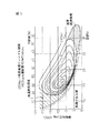
図4は不活性ガスとしてEGRガスを用いた場合において燃焼時の燃料およびその周囲のガス温度を煤が生成される温度よりも低い温度にするために必要なEGRガスと空気の混合ガス量、およびこの混合ガス量中の空気の割合、およびこの混合ガス中のEGRガスの割合を示している。なお、図4において縦軸は燃焼室5内に吸入される全吸入ガス量を示しており、鎖線Yは過給が行われないときに燃焼室5内に吸入しうる全吸入ガス量を示している。また、横軸は要求負荷を示している。
FIG. 4 shows the amount of mixed gas of EGR gas and air required to make the temperature of the fuel and the surrounding gas lower than the temperature at which soot is generated when EGR gas is used as the inert gas. And the ratio of the air in this gas mixture amount, and the ratio of the EGR gas in this gas mixture are shown. In FIG. 4, the vertical axis represents the total intake gas amount sucked into the
図4を参照すると空気の割合、即ち混合ガス中の空気量は噴射された燃料を完全に燃焼せしめるのに必要な空気量を示している。即ち、図4に示される場合では空気量と噴射燃料量との比は理論空燃比となっている。一方、図4においてEGRガスの割合、即ち混合ガス中のEGRガス量は噴射燃料が燃焼せしめられたときに燃料およびその周囲のガス温度を煤が形成される温度よりも低い温度にするのに必要最低限のEGRガス量を示している。このEGRガス量はEGR率で表すとほぼ55パーセント以上であり、図4に示す実施形態では70パーセント以上である。即ち、燃焼室5内に吸入された全吸入ガス量を図4において実線Xとし、この全吸入ガス量Xのうちの空気量とEGRガス量との割合を図4に示すような割合にすると燃料およびその周囲のガス温度は煤が生成される温度よりも低い温度となり、斯くして煤がほとんど発生しなくなる。また、このときのNOx発生量は10p.p.m 前後、又はそれ以下であり、従ってNOxの発生量は極めて少量となる。
Referring to FIG. 4, the ratio of air, that is, the amount of air in the mixed gas, indicates the amount of air necessary to completely burn the injected fuel. That is, in the case shown in FIG. 4, the ratio between the air amount and the injected fuel amount is the stoichiometric air-fuel ratio. On the other hand, in FIG. 4, the ratio of EGR gas, that is, the amount of EGR gas in the mixed gas is used to make the temperature of the fuel and its surrounding gas lower than the temperature at which soot is formed when the injected fuel is burned. The minimum EGR gas amount is shown. This EGR gas amount is approximately 55% or more in terms of EGR rate, and is 70% or more in the embodiment shown in FIG. That is, if the total intake gas amount sucked into the
燃料噴射量が増大すれば燃料が燃焼した際の発熱量が増大するので燃料およびその周囲のガス温度を煤が生成される温度よりも低い温度に維持するためにはEGRガスによる熱の吸収量を増大しなければならない。従って図4に示されるようにEGRガス量は噴射燃料量が増大するにつれて増大せしめなければならない。即ち、EGRガス量は要求負荷が高くなるにつれて増大する必要がある。 If the amount of fuel injection increases, the amount of heat generated when the fuel burns increases. Therefore, in order to maintain the temperature of the fuel and the surrounding gas at a temperature lower than the temperature at which soot is generated, the amount of heat absorbed by the EGR gas Must be increased. Therefore, as shown in FIG. 4, the EGR gas amount must be increased as the amount of injected fuel increases. That is, the amount of EGR gas needs to increase as the required load increases.
ところで過給が行われていない場合には燃焼室5内に吸入される全吸入ガス量Xの上限はYであり、従って図4において要求負荷がLo よりも大きい領域では要求負荷が大きくなるにつれてEGRガス割合が低下し理論空燃比に維持することができない。云い換えると過給が行われていない場合に要求負荷がLo よりも大きい領域において空燃比を理論空燃比に維持しようとした場合には要求負荷が高くなるにつれてEGR率が低下し、斯くして要求負荷がLo よりも大きい領域では燃料およびその周囲のガス温度を煤が生成される温度よりも低い温度に維持しえなくなる。
When the supercharging is not performed, the upper limit of the total intake gas amount X sucked into the
ところが図1に示されるようにEGR通路29を介して過給機の上流側即ち排気ターボチャージャ15のコンプレッサ16上流の空気吸込管17内にEGRガスを再循環させると要求負荷がLo よりも大きい領域においてEGR率を55パーセント以上、例えば70パーセントに維持することができ、斯くして燃料およびその周囲のガス温度を煤が生成される温度よりも低い温度に維持することができる。即ち、空気吸込管17内におけるEGR率が例えば70パーセントになるようにEGRガスを再循環させれば排気ターボチャージャ15のコンプレッサ16により昇圧された吸入ガスのEGR率も70パーセントとなり、斯くしてコンプレッサ16により昇圧しうる限度まで燃料およびその周囲のガス温度を煤が生成される温度よりも低い温度に維持することができる。従って、低温燃焼を生じさせることのできる機関の運転領域を拡大することができることになる。要求負荷がLo よりも大きい領域でEGR率を55パーセント以上にする際にはEGR制御弁31が全開せしめられる、スロットル弁20が若干閉弁せしめられる。
However, as shown in FIG. 1, when EGR gas is recirculated into the
前述したように図4は燃料を理論空燃比のもとで燃焼させる場合を示しているが空気量を図4に示される空気量よりも少くしても、即ち空燃比をリッチにしても煤の発生を阻止しつつNOxの発生量を10p.p.m 前後又はそれ以下にすることができ、また空気量を図4に示される空気量よりも多くしても、即ち空燃比の平均値を17から18のリーンにしても煤の発生を阻止しつつNOxの発生量を10p.p.m 前後又はそれ以下にすることができる。 As described above, FIG. 4 shows the case where the fuel is burned under the stoichiometric air-fuel ratio. However, even if the air amount is smaller than the air amount shown in FIG. The amount of NOx generated is 10 p. p. m or less, and even if the air amount is larger than the air amount shown in FIG. 4, that is, even if the average value of the air-fuel ratio is 17 to 18, lean generation is prevented. However, the amount of NOx generated is 10 p. p. It can be around m or less.
即ち、空燃比がリッチにされると燃料が過剰となるが燃焼温度が低い温度に抑制されているために過剰な燃料は煤まで成長せず、斯くして煤が生成されることがない。また、このときNOxも極めて少量しか発生しない。一方、平均空燃比がリーンのとき、或いは空燃比が理論空燃比のときでも燃焼温度が高くなれば少量の煤が生成されるが本発明では燃焼温度が低い温度に抑制されているので煤はほとんど生成されない。更に、NOxも極めて少量しか発生しない。 That is, when the air-fuel ratio is made rich, the fuel becomes excessive, but the combustion temperature is suppressed to a low temperature, so that the excess fuel does not grow to soot, and so no soot is generated. At this time, only a very small amount of NOx is generated. On the other hand, when the average air-fuel ratio is lean, or even when the air-fuel ratio is the stoichiometric air-fuel ratio, a small amount of soot is generated if the combustion temperature is high, but in the present invention the soot is suppressed to a low temperature so Almost no generation. Furthermore, only a very small amount of NOx is generated.
このように、低温燃焼が行われているときには空燃比にかかわらずに、即ち空燃比がリッチであろうと、理論空燃比であろうと、或いは平均空燃比がリーンであろうと煤がほとんど発生されず、NOxの発生量が極めて少量となる。従って燃料消費率の向上を考えるとこのとき平均空燃比をリーンにすることが好ましいと言える。 Thus, when low-temperature combustion is performed, soot is hardly generated regardless of the air-fuel ratio, that is, whether the air-fuel ratio is rich, the stoichiometric air-fuel ratio, or the average air-fuel ratio is lean. , NOx generation is extremely small. Therefore, considering the improvement of the fuel consumption rate, it can be said that it is preferable to make the average air-fuel ratio lean at this time.
ところで燃焼室内における燃焼時の燃料およびその周囲のガス温度を炭化水素の成長が途中で停止する温度以下に抑制しうるのは燃焼による発熱量が比較的少ない機関中低負荷運転時に限られる。従って本発明による実施形態では機関中低負荷運転時には燃焼時の燃料およびその周囲のガス温度を炭化水素の成長が途中で停止する温度以下に抑制して低温燃焼を行うようにし、機関高負荷運転時には従来より普通に行われている通常燃焼を行うようにしている。なお、ここで低温燃焼とはこれまでの説明から明らかなように煤の発生量がピークとなる不活性ガス量よりも燃焼室内の不活性ガス量が多く煤がほとんど発生しない燃焼のことを言い、従来より普通に行われている通常燃焼とは煤の発生量がピークとなる不活性ガス量よりも燃焼室内の不活性ガス量が少い燃焼のことを言う。 By the way, the temperature of the fuel during combustion in the combustion chamber and the surrounding gas temperature can be suppressed to a temperature equal to or lower than the temperature at which the growth of hydrocarbons stops midway, only when the engine medium-low load operation has a relatively small amount of heat generated by combustion. Therefore, in the embodiment according to the present invention, at the time of engine low load operation, the temperature of the fuel at the time of combustion and the surrounding gas temperature is controlled to be equal to or lower than the temperature at which hydrocarbon growth stops halfway, and low temperature combustion is performed. In some cases, normal combustion, which is conventionally performed, is performed. Note that the low-temperature combustion here refers to combustion in which the amount of inert gas in the combustion chamber is larger than the amount of inert gas at which soot generation peaks, and soot is hardly generated, as is apparent from the above description. Ordinary combustion, which is normally performed conventionally, refers to combustion in which the amount of inert gas in the combustion chamber is smaller than the amount of inert gas in which the amount of generated soot reaches a peak.
図5は特定の運転状態におけるスモーク濃度FSNと、低温燃焼領域および通常燃焼領域とを示す図であり、図6は低温燃焼領域と通常燃焼領域を示す概念図である。図5および図6などを用いて、煤の発生量がピークとなる不活性ガス量よりも燃焼室内の不活性ガス量が多く煤がほとんど発生しない燃焼である低温燃焼と、煤の発生量がピークとなる不活性ガス量よりも燃焼室内の不活性ガス量が少ない通常燃焼とを説明する。図5に示されるように煤の発生量がピークとなるEGR率の高EGR率側と低EGR率側に夫々低温燃焼領域と普通の燃焼領域とが存在している。また低温燃焼が行われるときには通常燃焼が行われるときに比べて噴射時期が進角側になるので、図5に示されるように低温燃焼領域は通常燃焼領域に比べて進角側になる。 FIG. 5 is a diagram showing the smoke concentration FSN, the low temperature combustion region and the normal combustion region in a specific operating state, and FIG. 6 is a conceptual diagram showing the low temperature combustion region and the normal combustion region. Using FIG. 5 and FIG. 6 and the like, low-temperature combustion, which is a combustion in which the amount of inert gas in the combustion chamber is larger than the amount of inert gas at which soot generation peaks, and soot is hardly generated, and the amount of soot generated is The normal combustion in which the amount of inert gas in the combustion chamber is smaller than the peak amount of inert gas will be described. As shown in FIG. 5, there are a low temperature combustion region and a normal combustion region on the high EGR rate side and the low EGR rate side of the EGR rate where the generation amount of soot peaks. In addition, when low temperature combustion is performed, the injection timing is advanced compared to when normal combustion is performed. Therefore, as shown in FIG. 5, the low temperature combustion region is advanced compared to the normal combustion region.
図6においては破線PはEGR率を増大したときに煤の発生量がピークになるところを示しており、実線QはEGR率をさらに増大したときに煤の発生量がほぼ零になるところを示している。図2および図6から分かるように通常燃焼と通常燃焼よりも進角側の低温燃焼とを切り替えるべくEGR率を増減させるとその間に煤の発生量がピークとなるところを通過する。また図2のように噴射時期を一定にした状態でEGR率を増大させた場合には図6において破線Pで示されるようにスモークの発生量にピークが発生する。そして、図6において通常燃焼領域から通常燃焼領域よりも進角側の低温燃焼領域に切り替えるべくEGR率を増大させると破線P上を通過するので、EGR率の増大中にスモークの発生量にピークが生じることとなる。 In FIG. 6, the broken line P indicates that the amount of soot generation peaks when the EGR rate is increased, and the solid line Q indicates that the amount of soot generation becomes almost zero when the EGR rate is further increased. Show. As can be seen from FIGS. 2 and 6, when the EGR rate is increased or decreased to switch between normal combustion and low-temperature combustion on the more advanced side than normal combustion, it passes through a point where the amount of soot generated reaches a peak. Further, when the EGR rate is increased with the injection timing kept constant as shown in FIG. 2, a peak occurs in the amount of smoke generated as shown by the broken line P in FIG. In FIG. 6, if the EGR rate is increased to switch from the normal combustion region to the low temperature combustion region on the more advanced side than the normal combustion region, it passes over the broken line P, so that a peak occurs in the amount of smoke generated during the increase of the EGR rate. Will occur.
図7は低温燃焼が行われる第1の運転領域Iと、従来の燃焼方法による通常燃焼が行われる第2の運転領域IIとを示している。なお、図7において縦軸Lはアクセルペダル50の踏込み量、即ち要求負荷を示しており、横軸Nは機関回転数を示している。また、図7においてX(N)は第1の運転領域Iと第2の運転領域IIとの第1の境界を示しており、Y(N)は第1の運転領域Iと第2の運転領域IIとの第2の境界を示している。第1の運転領域Iから第2の運転領域IIへの運転領域の変化判断は第1の境界X(N)に基づいて行われ、第2の運転領域IIから第1の運転領域Iへの運転領域の変化判断は第2の境界Y(N)に基づいて行われる。
FIG. 7 shows a first operation region I in which low-temperature combustion is performed and a second operation region II in which normal combustion is performed by a conventional combustion method. In FIG. 7, the vertical axis L indicates the amount of depression of the
即ち、機関の運転状態が第1の運転領域Iにあって低温燃焼が行われているときに要求負荷Lが機関回転数Nの関数である第1の境界X(N)を越えると運転領域が第2の運転領域IIに移ったと判断され、通常燃焼が行われる。次いで要求負荷Lが機関回転数Nの関数である第2の境界Y(N)よりも低くなると運転領域が第1の運転領域Iに移ったと判断され、再び低温燃焼が行われる。 That is, if the required load L exceeds the first boundary X (N) that is a function of the engine speed N when the engine operating state is in the first operating region I and low-temperature combustion is being performed, the operating region Is determined to have moved to the second operating region II, and normal combustion is performed. Next, when the required load L becomes lower than the second boundary Y (N) that is a function of the engine speed N, it is determined that the operating region has shifted to the first operating region I, and low temperature combustion is performed again.
このように第1の境界X(N)と第1の境界X(N)よりも低負荷側の第2の境界Y(N)との二つの境界を設けたのは次の二つの理由による。第1の理由は、第2の運転領域IIの高負荷側では比較的燃焼温度が高く、このとき要求負荷Lが第1の境界X(N)より低くなったとしてもただちに低温燃焼を行えないからである。即ち、要求負荷Lがかなり低くなったとき、即ち第2の境界Y(N)よりも低くなったときでなければただちに低温燃焼が開始されないからである。第2の理由は第1の運転領域Iと第2の運転領域II間の運転領域の変化に対してヒステリシスを設けるためである。 The reason for providing the two boundaries of the first boundary X (N) and the second boundary Y (N) on the lower load side than the first boundary X (N) is as follows. . The first reason is that the combustion temperature is relatively high on the high load side of the second operation region II, and at this time, even if the required load L becomes lower than the first boundary X (N), the low temperature combustion cannot be performed immediately. Because. That is, low temperature combustion is not started immediately unless the required load L is considerably low, that is, when the required load L is lower than the second boundary Y (N). The second reason is to provide hysteresis with respect to a change in the operation region between the first operation region I and the second operation region II.
ところで機関の運転領域が第1の運転領域Iにあって低温燃焼が行われているときには煤はほとんど発生せず、その代り未燃炭化水素が煤の前駆体又はその前の状態の形でもって燃焼室5から排出される。このとき燃焼室5から排出された未燃炭化水素はフィルタ25に担持された酸化機能を有する触媒(吸蔵還元型NOx触媒)により良好に酸化せしめられる。同時に排気微粒子はフィルタ25によって捕集される。
By the way, when the engine operating region is in the first operating region I and low-temperature combustion is performed, soot is hardly generated, and instead, the unburned hydrocarbon is in the form of soot precursor or the previous state. It is discharged from the
このNOx触媒は例えばアルミナを担体とし、この担体上に例えばカリウムK、ナトリウムNa、リチウムLi、セシウムCsのようなアルカリ金属、バリウムBa、カルシウムCaのようなアルカリ土類、ランタンLa、イットリウムYのような希土類から選ばれた少くとも一つと、白金Ptのような貴金属とが担持されている。 This NOx catalyst has, for example, alumina as a carrier, and on this carrier, for example, alkali metal such as potassium K, sodium Na, lithium Li, cesium Cs, alkaline earth such as barium Ba, calcium Ca, lanthanum La, yttrium Y, etc. At least one selected from such rare earths and a noble metal such as platinum Pt are supported.
図8は空燃比センサ27の出力を示している。図8に示されるように空燃比センサ27の出力電流Iは空燃比A/Fに応じて変化する。従って空燃比センサ27の出力電流Iから空燃比を知ることができる。
FIG. 8 shows the output of the air-
次に図9を参照しつつ第1の運転領域Iおよび第2の運転領域IIにおける運転制御について概略的に説明する。 Next, operation control in the first operation region I and the second operation region II will be schematically described with reference to FIG.
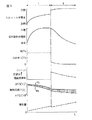
図9は要求負荷Lに対するスロットル弁20の開度、EGR制御弁31の開度、EGR率、空燃比、噴射時期および噴射量を示している。図9に示されるように要求負荷Lの低い第1の運転領域Iではスロットル弁20の開度は要求負荷Lが高くなるにつれて全閉近くから2/3開度程度まで徐々に増大せしめられ、EGR制御弁31の開度は要求負荷Lが高くなるにつれて全閉近くから全開まで徐々に増大せしめられる。また、図9に示される例では第1の運転領域IではEGR率がほぼ70パーセントとされており、空燃比はわずかばかりリーンなリーン空燃比とされている。
FIG. 9 shows the opening degree of the
言い換えると第1の運転領域IではEGR率がほぼ70パーセントとなり、空燃比がわずかばかりリーンなリーン空燃比となるようにスロットル弁20の開度および第2のEGR制御弁31の開度が制御される。また、第1の運転領域Iでは圧縮上死点TDC前に燃料噴射が行われる。この場合、噴射開始時期θSは要求負荷Lが高くなるにつれて遅くなり、噴射完了時期θEも噴射開始時期θSが遅くなるにつれて遅くなる。
In other words, the opening degree of the
なお、アイドル運転時にはスロットル弁20は全閉近くまで閉弁され、このとき第2のEGR制御弁31も全閉近くまで閉弁せしめられる。スロットル弁20を全閉近くまで閉弁すると圧縮始めの燃焼室5内の圧力が低くなるために圧縮圧力が小さくなる。圧縮圧力が小さくなるとピストン4による圧縮仕事が小さくなるために機関本体1の振動が小さくなる。即ち、アイドル運転時には機関本体1の振動を抑制するためにスロットル弁20が全閉近くまで閉弁せしめられる。
During idle operation, the
一方、機関の運転領域が第1の運転領域Iから第2の運転領域IIに変わるとスロットル弁20の開度が2/3開度程度から全開方向へステップ状に増大せしめられる。このとき図9に示す例ではEGR率がほぼ70パーセントから40パーセント以下までステップ状に減少せしめられ、空燃比がステップ状に大きくされる。即ち、EGR率が多量のスモークを発生するEGR率範囲(図5)を飛び越えるので機関の運転領域が第1の運転領域Iから第2の運転領域IIに変わるときに多量のスモークが発生することがない。
On the other hand, when the operating range of the engine is changed from the first operating range I to the second operating range II, the opening degree of the
第2の運転領域IIでは通常燃焼が行われる。この第2の運転領域IIではスロットル弁20は一部を除いて全開状態に保持され、第2のEGR制御弁31の開度は要求負荷Lが高くなると次第に小さくされる。また、この運転領域IIではEGR率は要求負荷Lが高くなるほど低くなり、空燃比は要求負荷Lが高くなるほど小さくなる。ただし、空燃比は要求負荷Lが高くなってもリーン空燃比とされる。また、第2の運転領域IIでは噴射開始時期θSは圧縮上死点TDC付近とされる。
In the second operation region II, normal combustion is performed. In the second operation region II, the
図10(A)は第1の運転領域Iにおける目標空燃比A/Fを示している。図10(A)において、A/F=15.5,A/F=16,A/F=17,A/F=18で示される各曲線は夫々目標空燃比が15.5,16,17,18であるときを示しており、各曲線間の空燃比は比例配分により定められる。図10(A)に示されるように第1の運転領域Iでは空燃比がリーンとなっており、更に第1の運転領域Iでは要求負荷Lが低くなるほど目標空燃比A/Fがリーンとされる。 FIG. 10A shows the target air-fuel ratio A / F in the first operation region I. In FIG. 10A, each of the curves indicated by A / F = 15.5, A / F = 16, A / F = 17, A / F = 18 has a target air-fuel ratio of 15.5, 16, 17 respectively. , 18, and the air-fuel ratio between the curves is determined by proportional distribution. As shown in FIG. 10 (A), the air-fuel ratio is lean in the first operating region I, and in the first operating region I, the target air-fuel ratio A / F is made lean as the required load L becomes lower. The
即ち、要求負荷Lが低くなるほど燃焼による発熱量が少くなる。従って要求負荷Lが低くなるほどEGR率を低下させても低温燃焼を行うことができる。EGR率を低下させると空燃比は大きくなり、従って図10(A)に示されるように要求負荷Lが低くなるにつれて目標空燃比A/Fが大きくされる。目標空燃比A/Fが大きくなるほど燃料消費率は向上し、従ってできる限り空燃比をリーンにするために本発明による実施形態では要求負荷Lが低くなるにつれて目標空燃比A/Fが大きくされる。 That is, the lower the required load L, the smaller the amount of heat generated by combustion. Therefore, low temperature combustion can be performed even if the EGR rate is reduced as the required load L is reduced. When the EGR rate is decreased, the air-fuel ratio increases, and therefore the target air-fuel ratio A / F is increased as the required load L decreases as shown in FIG. As the target air-fuel ratio A / F increases, the fuel consumption rate improves. Therefore, in order to make the air-fuel ratio as lean as possible, in the embodiment according to the present invention, the target air-fuel ratio A / F increases as the required load L decreases. .
なお、図10(A)に示される目標空燃比A/Fは図10(B)に示されるように要求負荷Lおよび機関回転数Nの関数としてマップの形で予めROM42内に記憶されている。また、空燃比を図10(A)に示す目標空燃比A/Fとするのに必要なスロットル弁20の目標開度STが図11(A)に示されるように要求負荷Lおよび機関回転数Nの関数としてマップの形で予めROM42内に記憶されており、空燃比を図10(A)に示す目標空燃比A/Fとするのに必要な第1のEGR制御弁64の開度SELと第2のEGR制御弁31の開度SEHとの合計である目標合計開度SEが図11(B)に示されるように要求負荷Lおよび機関回転数Nの関数としてマップの形で予めROM42内に記憶されている。第1のEGR制御弁64の開度SELと第2のEGR制御弁31の開度SEHとの比については、後で詳細に説明する。
The target air-fuel ratio A / F shown in FIG. 10 (A) is stored in advance in the
図12(A)は通常燃焼が行われるときの目標空燃比A/Fを示している。なお、図12(A)においてA/F=24,A/F=35,A/F=45,A/F=60で示される各曲線は夫々目標空燃比24,35,45,60を示している。図12(A)に示される目標空燃比A/Fは図12(B)に示されるように要求負荷Lおよび機関回転数Nの関数としてマップの形で予めROM42内に記憶されている。また、空燃比を図12(A)に示す目標空燃比A/Fとするのに必要なスロットル弁20の目標開度STが図13(A)に示されるように要求負荷Lおよび機関回転数Nの関数としてマップの形で予めROM42内に記憶されており、空燃比を図12(A)に示す目標空燃比A/Fとするのに必要な第1のEGR制御弁64の開度SELとなる目標開度SEが図13(B)に示されるように要求負荷Lおよび機関回転数Nの関数としてマップの形で予めROM42内に記憶されている。
FIG. 12A shows the target air-fuel ratio A / F when normal combustion is performed. In FIG. 12A, the curves indicated by A / F = 24, A / F = 35, A / F = 45, and A / F = 60 indicate the target air-
また、通常燃焼が行われているときには燃料噴射量Qは要求負荷Lおよび機関回転数Nに基づいて算出される。この燃料噴射量Qは図14に示されるように要求負荷Lおよび機関回転数Nの関数としてマップの形で予めROM42内に記憶されている。
When normal combustion is being performed, the fuel injection amount Q is calculated based on the required load L and the engine speed N. The fuel injection amount Q is stored in advance in the
次に図15を参照しつつ運転制御について説明する。図15を参照すると、まず初めにステップ100において機関の運転状態が第1の運転領域Iであることを示すフラグIがセットされているか否かが判別される。フラグIがセットされているとき、即ち機関の運転状態が第1の運転領域Iであるときにはステップ101に進んで要求負荷Lが第1の境界X1(N)よりも大きくなったか否かが判別される。L≦X1(N)のときにはステップ103に進んで低温燃焼が行われる。
Next, operation control will be described with reference to FIG. Referring to FIG. 15, first, at
即ち、ステップ103では図11(A)に示すマップからスロットル弁20の目標開度STが算出され、スロットル弁20の開度がこの目標開度STとされる。次いでステップ104では図11(B)に示すマップから第2のEGR制御弁31の目標開度SEが算出され、EGR制御弁31の開度がこの目標開度SEとされる。次いでステップ105では図10に示される空燃比となるように燃料噴射が行われる。このとき低温燃焼が行われる。
That is, in
一方、ステップ101においてL>X(N)になったと判別されたときにはステップ102に進んでフラグIがリセットされ、次いでステップ108に進んで第2の燃焼が行われる。即ち、ステップ108では図13(A)に示すマップからスロットル弁20の目標開度STが算出され、スロットル弁20の開度がこの目標開度STとされる。次いでステップ109では図13(B)に示すマップから第2のEGR制御弁31の目標開度SEが算出され、EGR制御弁31の開度がこの目標開度SEとされる。次いでステップ110では図12に示されるリーン空燃比となるように燃料噴射が行われる。
On the other hand, when it is determined in
フラグIがリセットされると次の処理サイクルではステップ100からステップ106に進んで要求負荷Lが第2の境界Y(N)よりも低くなったか否かが判別される。L≧Y(N)のときにはステップ108に進み、リーン空燃比のもとで通常燃焼が行われる。一方、ステップ106においてL<Y(N)になったと判別されたときにはステップ107に進んでフラグIがセットされ、次いでステップ103に進んで低温燃焼が行われる。
When the flag I is reset, in the next processing cycle, the routine proceeds from
ところで、前述した内燃機関の運転制御においては、ステップ103およびステップ108においてスロットル弁20の開度を設定すると共に、ステップ104およびステップ109においては第1のEGR制御弁64の開度を設定している。このように弁の開度を設定すると、吸気ガスおよび再循環排気ガスがそれぞれ設定された開度に応じた流量で流れるようになる。ここで、従来技術の内燃機関においてはスロットル弁により流量調整された吸気ガスはターボチャージャのコンプレッサおよびインタークーラを通過して燃焼室に到達しており、EGR制御弁により流量調整されたEGRガスも同様にターボチャージャのコンプレッサおよびインタークーラを通過して燃焼室に到達していた。このため、従来技術の内燃機関においては前述したインタークーラ等の残存EGRガスを押し出した後に新規のガスが燃焼室に到達するのでレスポンスに欠けていた。しかしながら、図1に示すような本発明の内燃機関においては第1のEGR制御弁64はEGRガスコンプレッサ65の下流に設けられ、かつEGR通路61はインタークーラ14の下流に位置するサージタンク12に接続しているので、EGRガスがEGRガスコンプレッサ65を通過することがない。さらに、図1においてはEGR通路61はインタークーラ14の下流に位置するサージタンク12に接続しているので、EGRガスがインタークーラ14を通過することもない。このため、EGR制御弁64を開弁してEGRガス量を増大させるときの内燃機関のレスポンスを高めることができる。
By the way, in the above-described operation control of the internal combustion engine, the opening degree of the
同様に、図1におけるスロットル弁20はコンプレッサ16およびインタークーラ14の下流に設けられており、かつEGR通路61がスロットル弁20の下流に位置するサージタンクに接続されている。加速時にスロットル弁20を開弁した際、コンプレッサ16およびインタークーラ14内にEGRガスが存在しない(残存しない)ので、新規の吸気が直ちに燃焼室5に供給される。このため、スロットル弁20を開弁して吸気ガス量を増大させるときの内燃機関のレスポンスを高めることが可能となる。
Similarly, the
さらに図1に示される実施形態においては排気ターボチャージャ15の排気タービン23により駆動されるEGRガスコンプレッサ65がEGR通路61に設けられており、これにより、大量のEGRガスを燃焼室に迅速に供給することができる。従来技術においてはEGRガスと吸気ガスとの両方を単一のコンプレッサによって燃焼室に供給していたので、機関要求負荷が高い場合には大量のEGRガスを供給するのが困難であるが、本発明においてはEGRガスを昇圧するためのEGRガスコンプレッサ65を設けているので、機関要求負荷が高い場合であっても大量のEGRガスを供給することができ、これにより、機関要求負荷が高い場合であっても低温燃焼を行うことが可能である。
Further, in the embodiment shown in FIG. 1, an
また、前述したNOx吸蔵還元型触媒を備えた内燃機関のリーン制御運転時に、触媒のNOx吸収量が飽和する前に、そのNOxを浄化するため、機関シリンダ内に供給される混合気の空燃比を一時的にリッチにすることにより、NOx吸蔵還元型触媒に流入する排気ガスの酸素濃度を低下させ、NOxを放出・還元させるリッチスパイク制御が行われている。空燃比を一時的にリッチにする際にはEGRガス量を増大するようにしているが、機関要求負荷が高い場合には大量のEGRガスを燃焼室5に供給するのが困難である。しかしながら、前述したように本発明においてはEGRガスコンプレッサ65を使用することにより、機関要求負荷が高い場合であっても大量のEGRガスを供給することができ、これにより、リッチスパイク制御可能領域の拡大も可能となる。
Further, during the lean control operation of the internal combustion engine provided with the NOx occlusion reduction catalyst described above, the air-fuel ratio of the air-fuel mixture supplied into the engine cylinder is used to purify the NOx before the NOx absorption amount of the catalyst is saturated. Is temporarily rich to reduce the oxygen concentration of the exhaust gas flowing into the NOx occlusion reduction catalyst, and to perform rich spike control for releasing and reducing NOx. When the air-fuel ratio is temporarily made rich, the EGR gas amount is increased. However, when the engine required load is high, it is difficult to supply a large amount of EGR gas to the
ところで、内燃機関における排気ターボチャージャ15の吸気ガス用のコンプレッサ16は排気タービン23によって駆動されるようになっている。コンプレッサ16により圧縮されるエアクリーナ18からの空気はほぼ常温であるので、コンプレッサ16の材料には耐熱性は要求されないが、排気タービン23を通る排気ガスは高温であるので排気タービン23の材料には耐熱性が要求される。図1から分かるように、本発明においては排気通路を流れる排気ガスの一部がEGRガスとしてEGRガスコンプレッサ65を通過するようになっている。つまり、EGRガス自体は元々排気ガスであるので高温である上に、この排気ガスは触媒コンバータ26を通過する際の酸化反応によってさらに高温になっているのでEGRガスの温度はかなり高くなる。このため、コンプレッサ16の製造に使用されるような耐熱性の低い材料からEGRガスコンプレッサ65を形成した場合には、高温のEGRガスによってEGRガスコンプレッサ65が破損する可能性があるが、本発明においては図1に示されるようなEGRクーラ62がEGRガスコンプレッサ65の上流に設けられている。従って、EGRガスコンプレッサ65を通過する前にEGRクーラ62によってEGRガスを冷却することができる。つまり、EGRガスコンプレッサ65内に進入するEGRガスの温度が低くなっているので、耐熱性の低い材料からEGRガスコンプレッサ65形成したとしても、EGRガスコンプレッサ65が熱により破損するのを回避できる。
Incidentally, the
なお、第一の実施形態においては排気ターボチャージャ15の排気タービン23により駆動するEGRガスコンプレッサ65が示されているが、このEGRガスコンプレッサ65は必ずしも排気タービン23により駆動される必要はなく、他の駆動源、例えば別途設けられたモータによって駆動されるようにしてもよい。
Although the
前述した実施形態においてはEGR通路61はサージタンク12に直結するように示されているが、EGR通路61がインタークーラ14下流に位置する吸気ダクト13に接続されている場合であっても本発明の範囲に含まれるのは明らかである。
In the above-described embodiment, the
1…内燃機関
5…燃焼室
6…燃料噴射弁
14…インタークーラ
15…ターボチャージャ
16…コンプレッサ(吸気ガスコンプレッサ)
20…スロットル弁
23…排気タービン
25…酸化機能を有する触媒(吸蔵還元型NOx触媒)を担持したフィルタ
61…EGR通路(排気ガス再循環通路)
62…EGRクーラ(冷却装置)
64…EGR制御弁(再循環排気ガス制御弁)
65…EGRガスコンプレッサ(再循環排気ガスコンプレッサ)
DESCRIPTION OF
DESCRIPTION OF
62 ... EGR cooler (cooling device)
64 ... EGR control valve (recirculation exhaust gas control valve)
65 ... EGR gas compressor (recirculation exhaust gas compressor)
Claims (4)
前記排気ガス循環装置が、排気ガス再循環通路と、該排気ガス再循環通路を流れる再循環排気ガスの量を制御可能な再循環排気ガス制御弁と、前記排気ガス再循環通路内において前記再循環排気ガスを昇圧するための再循環排気ガスコンプレッサとを具備しており、
前記再循環排気ガス制御弁が前記再循環排気ガスコンプレッサの下流に設けられると共に、前記機関吸気通路内におけるスロットル弁が前記内燃機関の前記吸気通路に設けられたインタークーラの下流に配置され、かつ前記排気ガス再循環通路の出口部が前記スロットル弁下流の吸気通路に接続されるようにした内燃機関。 An exhaust gas recirculation device that recirculates exhaust gas discharged from the combustion chamber into the engine intake passage is provided, and when the amount of recirculated exhaust gas supplied to the combustion chamber is increased, the amount of soot generated is increased. As the amount of recirculated exhaust gas supplied into the combustion chamber increases further and gradually reaches a peak, the temperature of the fuel and the surrounding gas in the combustion chamber is lower than the soot generation temperature. Switching means for switching between low-temperature combustion in which soot is hardly generated and normal combustion in which the amount of inert gas supplied to the combustion chamber is smaller than the amount of inert gas in which the amount of soot reaches a peak, and the engine In an internal combustion engine comprising an intake gas compressor provided in an intake passage and a turbocharger driven by a turbine provided in an engine exhaust passage,
The exhaust gas circulation device includes an exhaust gas recirculation passage, a recirculation exhaust gas control valve capable of controlling the amount of recirculation exhaust gas flowing through the exhaust gas recirculation passage, and the recirculation gas in the exhaust gas recirculation passage. A recirculation exhaust gas compressor for boosting the circulation exhaust gas,
The recirculation exhaust gas control valve is provided downstream of the recirculation exhaust gas compressor, a throttle valve in the engine intake passage is disposed downstream of an intercooler provided in the intake passage of the internal combustion engine, and An internal combustion engine in which an outlet portion of the exhaust gas recirculation passage is connected to an intake passage downstream of the throttle valve.
Priority Applications (1)
| Application Number | Priority Date | Filing Date | Title |
|---|---|---|---|
| JP2003306690A JP2005076502A (en) | 2003-08-29 | 2003-08-29 | Internal combustion engine |
Applications Claiming Priority (1)
| Application Number | Priority Date | Filing Date | Title |
|---|---|---|---|
| JP2003306690A JP2005076502A (en) | 2003-08-29 | 2003-08-29 | Internal combustion engine |
Publications (2)
| Publication Number | Publication Date |
|---|---|
| JP2005076502A true JP2005076502A (en) | 2005-03-24 |
| JP2005076502A5 JP2005076502A5 (en) | 2006-02-02 |
Family
ID=34409711
Family Applications (1)
| Application Number | Title | Priority Date | Filing Date |
|---|---|---|---|
| JP2003306690A Pending JP2005076502A (en) | 2003-08-29 | 2003-08-29 | Internal combustion engine |
Country Status (1)
| Country | Link |
|---|---|
| JP (1) | JP2005076502A (en) |
Cited By (4)
| Publication number | Priority date | Publication date | Assignee | Title |
|---|---|---|---|---|
| JP2009115089A (en) * | 2007-11-07 | 2009-05-28 | Ford Global Technologies Llc | Engine with supercharger and its operating method |
| EP2295779A1 (en) * | 2009-08-04 | 2011-03-16 | International Engine Intellectual Property Company, LLC | System using supplemental compressor for EGR |
| CN102410091A (en) * | 2010-09-20 | 2012-04-11 | 万国引擎知识产权有限责任公司 | Device and method for protecting tail gas recycle valve from scaling |
| GB2564690A (en) * | 2017-07-20 | 2019-01-23 | Ford Global Tech Llc | An EGR system |
-
2003
- 2003-08-29 JP JP2003306690A patent/JP2005076502A/en active Pending
Cited By (6)
| Publication number | Priority date | Publication date | Assignee | Title |
|---|---|---|---|---|
| JP2009115089A (en) * | 2007-11-07 | 2009-05-28 | Ford Global Technologies Llc | Engine with supercharger and its operating method |
| EP2295779A1 (en) * | 2009-08-04 | 2011-03-16 | International Engine Intellectual Property Company, LLC | System using supplemental compressor for EGR |
| CN101994605A (en) * | 2009-08-04 | 2011-03-30 | 万国引擎知识产权有限责任公司 | System using supplemental compressor for EGR |
| CN102410091A (en) * | 2010-09-20 | 2012-04-11 | 万国引擎知识产权有限责任公司 | Device and method for protecting tail gas recycle valve from scaling |
| GB2564690A (en) * | 2017-07-20 | 2019-01-23 | Ford Global Tech Llc | An EGR system |
| GB2564690B (en) * | 2017-07-20 | 2019-08-14 | Ford Global Tech Llc | A turbocharger having a second compressor for an EGR system |
Similar Documents
| Publication | Publication Date | Title |
|---|---|---|
| JP4042649B2 (en) | Internal combustion engine | |
| JP3552645B2 (en) | Internal combustion engine | |
| JP3555559B2 (en) | Internal combustion engine | |
| JPH11257054A (en) | Compression ignition internal combustion engine | |
| JP2000145509A (en) | Internal combustion engine | |
| JP3539238B2 (en) | Internal combustion engine | |
| JP3551790B2 (en) | Internal combustion engine | |
| JP2005076502A (en) | Internal combustion engine | |
| JP3551794B2 (en) | Internal combustion engine | |
| JP3405217B2 (en) | Internal combustion engine | |
| JP3551788B2 (en) | Compression ignition type internal combustion engine | |
| JP3555439B2 (en) | Compression ignition type internal combustion engine | |
| JP3551771B2 (en) | Internal combustion engine | |
| JP3551768B2 (en) | Internal combustion engine | |
| JP3551797B2 (en) | Internal combustion engine | |
| JP3424571B2 (en) | Internal combustion engine | |
| JP3344334B2 (en) | Internal combustion engine | |
| JP3807209B2 (en) | Operation control device for internal combustion engine | |
| JP3427754B2 (en) | Internal combustion engine | |
| JP3551785B2 (en) | Internal combustion engine | |
| JP2000179411A (en) | Exhaust gas recirculating rate control valve | |
| JP3424554B2 (en) | Internal combustion engine | |
| JP3424570B2 (en) | Internal combustion engine | |
| JP3092597B2 (en) | Internal combustion engine | |
| JP3551769B2 (en) | Internal combustion engine |
Legal Events
| Date | Code | Title | Description |
|---|---|---|---|
| A521 | Written amendment |
Free format text: JAPANESE INTERMEDIATE CODE: A523 Effective date: 20051213 |
|
| A621 | Written request for application examination |
Free format text: JAPANESE INTERMEDIATE CODE: A621 Effective date: 20051213 |
|
| A977 | Report on retrieval |
Free format text: JAPANESE INTERMEDIATE CODE: A971007 Effective date: 20070427 |
|
| A131 | Notification of reasons for refusal |
Free format text: JAPANESE INTERMEDIATE CODE: A131 Effective date: 20070522 |
|
| A521 | Written amendment |
Free format text: JAPANESE INTERMEDIATE CODE: A523 Effective date: 20070719 |
|
| A02 | Decision of refusal |
Free format text: JAPANESE INTERMEDIATE CODE: A02 Effective date: 20071023 |