JP2005073764A - System and method for angiographic measuring and imaging obtained by combining x-ray ct apparatus and ultrasonography - Google Patents
System and method for angiographic measuring and imaging obtained by combining x-ray ct apparatus and ultrasonography Download PDFInfo
- Publication number
- JP2005073764A JP2005073764A JP2003304959A JP2003304959A JP2005073764A JP 2005073764 A JP2005073764 A JP 2005073764A JP 2003304959 A JP2003304959 A JP 2003304959A JP 2003304959 A JP2003304959 A JP 2003304959A JP 2005073764 A JP2005073764 A JP 2005073764A
- Authority
- JP
- Japan
- Prior art keywords
- ray
- region
- imaging
- contrast agent
- subject
- Prior art date
- Legal status (The legal status is an assumption and is not a legal conclusion. Google has not performed a legal analysis and makes no representation as to the accuracy of the status listed.)
- Pending
Links
- 238000003384 imaging method Methods 0.000 title claims abstract description 52
- 238000000034 method Methods 0.000 title abstract description 8
- 238000002604 ultrasonography Methods 0.000 title abstract 4
- 239000002872 contrast media Substances 0.000 claims abstract description 62
- 238000005259 measurement Methods 0.000 claims abstract description 37
- 238000012544 monitoring process Methods 0.000 claims abstract description 30
- 239000000523 sample Substances 0.000 claims abstract description 12
- 238000011144 upstream manufacturing Methods 0.000 claims abstract description 4
- 230000017531 blood circulation Effects 0.000 claims description 24
- 238000002347 injection Methods 0.000 claims description 23
- 239000007924 injection Substances 0.000 claims description 23
- 239000002961 echo contrast media Substances 0.000 claims description 22
- 238000007689 inspection Methods 0.000 claims description 17
- 238000005206 flow analysis Methods 0.000 claims description 10
- 210000003462 vein Anatomy 0.000 claims description 7
- 238000002583 angiography Methods 0.000 claims description 5
- 230000004087 circulation Effects 0.000 claims description 5
- 239000008280 blood Substances 0.000 claims description 2
- 210000004369 blood Anatomy 0.000 claims description 2
- 230000007274 generation of a signal involved in cell-cell signaling Effects 0.000 claims 1
- 238000001802 infusion Methods 0.000 abstract 1
- 238000004458 analytical method Methods 0.000 description 8
- 210000001715 carotid artery Anatomy 0.000 description 8
- 230000010412 perfusion Effects 0.000 description 8
- 238000012545 processing Methods 0.000 description 8
- 238000013170 computed tomography imaging Methods 0.000 description 7
- 238000001514 detection method Methods 0.000 description 3
- 238000010586 diagram Methods 0.000 description 3
- 210000004185 liver Anatomy 0.000 description 3
- 210000001367 artery Anatomy 0.000 description 2
- 238000003745 diagnosis Methods 0.000 description 2
- 238000007781 pre-processing Methods 0.000 description 2
- 238000002360 preparation method Methods 0.000 description 2
- 230000003187 abdominal effect Effects 0.000 description 1
- 238000010521 absorption reaction Methods 0.000 description 1
- 230000001133 acceleration Effects 0.000 description 1
- 210000000709 aorta Anatomy 0.000 description 1
- 230000005540 biological transmission Effects 0.000 description 1
- 210000004204 blood vessel Anatomy 0.000 description 1
- 238000004364 calculation method Methods 0.000 description 1
- 230000003727 cerebral blood flow Effects 0.000 description 1
- 230000002490 cerebral effect Effects 0.000 description 1
- 238000012790 confirmation Methods 0.000 description 1
- 201000010099 disease Diseases 0.000 description 1
- 208000037265 diseases, disorders, signs and symptoms Diseases 0.000 description 1
- 230000009977 dual effect Effects 0.000 description 1
- 238000011156 evaluation Methods 0.000 description 1
- 210000002767 hepatic artery Anatomy 0.000 description 1
- 238000012905 input function Methods 0.000 description 1
- 230000001678 irradiating effect Effects 0.000 description 1
- 230000003211 malignant effect Effects 0.000 description 1
- 239000000463 material Substances 0.000 description 1
- 230000000414 obstructive effect Effects 0.000 description 1
- 210000003240 portal vein Anatomy 0.000 description 1
- 238000004445 quantitative analysis Methods 0.000 description 1
- 230000005855 radiation Effects 0.000 description 1
- 230000002123 temporal effect Effects 0.000 description 1
- 230000002792 vascular Effects 0.000 description 1
Images

Classifications
-
- A—HUMAN NECESSITIES
- A61—MEDICAL OR VETERINARY SCIENCE; HYGIENE
- A61B—DIAGNOSIS; SURGERY; IDENTIFICATION
- A61B6/00—Apparatus or devices for radiation diagnosis; Apparatus or devices for radiation diagnosis combined with radiation therapy equipment
- A61B6/50—Apparatus or devices for radiation diagnosis; Apparatus or devices for radiation diagnosis combined with radiation therapy equipment specially adapted for specific body parts; specially adapted for specific clinical applications
- A61B6/507—Apparatus or devices for radiation diagnosis; Apparatus or devices for radiation diagnosis combined with radiation therapy equipment specially adapted for specific body parts; specially adapted for specific clinical applications for determination of haemodynamic parameters, e.g. perfusion CT
Landscapes
- Health & Medical Sciences (AREA)
- Life Sciences & Earth Sciences (AREA)
- Medical Informatics (AREA)
- Engineering & Computer Science (AREA)
- Optics & Photonics (AREA)
- Biomedical Technology (AREA)
- Biophysics (AREA)
- High Energy & Nuclear Physics (AREA)
- Oral & Maxillofacial Surgery (AREA)
- Nuclear Medicine, Radiotherapy & Molecular Imaging (AREA)
- Dentistry (AREA)
- Pathology (AREA)
- Radiology & Medical Imaging (AREA)
- Physics & Mathematics (AREA)
- Heart & Thoracic Surgery (AREA)
- Molecular Biology (AREA)
- Surgery (AREA)
- Animal Behavior & Ethology (AREA)
- General Health & Medical Sciences (AREA)
- Public Health (AREA)
- Veterinary Medicine (AREA)
- Apparatus For Radiation Diagnosis (AREA)
- Ultra Sonic Daignosis Equipment (AREA)
Abstract
Description
本発明は、X線CT装置を使った造影検査システムおよび方法の改良であって、具体的には、X線CT装置と超音波検査装置を組み合せた血管造影計測撮影システムおよび方法に関する。 The present invention relates to an improvement of a contrast examination system and method using an X-ray CT apparatus, and more specifically to an angiography measurement imaging system and method combining an X-ray CT apparatus and an ultrasonic examination apparatus.
X線CT装置を使った造影検査は、単にコントラストを増加させる目的だけでなく、良性、悪性の確定等の質的診断や血流循環動態を評価するためにも用いられている。 Contrast examination using an X-ray CT apparatus is used not only for the purpose of increasing contrast, but also for qualitative diagnosis such as benign and malignant confirmation and evaluation of blood circulation.
血管の描出などコントラストを増加させる目的の場合は、関心領域における造影剤濃度が最大となる時間にタイミングを合わせて計測を開始する。 For the purpose of increasing contrast, such as the depiction of blood vessels, the measurement is started at the timing when the contrast agent concentration in the region of interest becomes maximum.
肝臓などについて質的診断をする目的の場合は、動脈が優位に造影されている時相や、静脈が優位に造影されている時相などを選択して繰り返し撮影する。しかし、被検体の個体差や病体などによって関心領域への造影剤到達時間はまちまちなため、完璧な撮影条件を決定することは難しい。一般的な手法としては、操作者が被検体の病体などを基に経験的に撮影条件、特にタイミングを決定するため、時として十分なコントラストが得られないことがあった。 For the purpose of qualitative diagnosis of the liver and the like, the time phase in which the artery is preferentially contrasted and the time phase in which the vein is preferentially contrasted are selected and photographed repeatedly. However, it is difficult to determine perfect imaging conditions because the contrast agent arrival time to the region of interest varies depending on individual differences of subjects and diseased bodies. As a general technique, since the operator empirically determines the imaging conditions, particularly the timing, based on the diseased body of the subject, sometimes a sufficient contrast cannot be obtained.
X線CT装置を使ったもう1つの造影検査である頭部や肝臓などについて行われるパーフュージョン検査は血流の循環動態の評価を目的とするもので、らせんスキャンではなく同一断面を連続的にダイナミック撮影し、撮影断面についての造影剤の時間−濃度変化を取得する。得られた撮影断面中の各組織の造影剤の時間濃度曲線(以下、TDC:Time Density Curve)から、局所脳血流量(rCBF)、局所脳血液量(rCBV)、平均通過時間(MTT)などの解析値を求め、例えば、解析値の分布画像(機能画像)で閉塞性疾患などを評価する。 Perfusion examinations, such as the head and liver, which are another contrast examination using an X-ray CT system, are intended to evaluate blood flow circulatory dynamics. Dynamic imaging is performed, and the time-concentration change of the contrast agent for the imaging section is acquired. From the time density curve (hereinafter referred to as TDC: Time Density Curve) of each tissue in the obtained cross section, local cerebral blood flow (rCBF), local cerebral blood volume (rCBV), average transit time (MTT), etc. For example, an obstructive disease or the like is evaluated using a distribution image (functional image) of the analysis value.
パーフュージョン検査の場合は、血流の第1循環成分が解析対象となるため、TDCの立ち上がりから、再循環成分までを含む(第1循環成分を推定できれば良い)データが必要である。一般的にこの撮影時間は40〜50秒間で、造影剤の集中を評価するため造影剤到達に先立って計測を開始する。特にパーフュージョン検査の場合、同一断面にX線をくり返し照射するため被曝はできるだけ抑える必要があるにもかかわらずX線造影剤注入開始時間とCT撮影開始時間の間のディレイタイムは、TDCの立ち上がりが確実に計測できるように余裕を持って設定する必要があるため、理想的には造影剤到達直前のデータがあれば良いのだが、それ以前からX線の照射を開始し、これらは結果的には無効被曝となっていた。 In the case of the perfusion examination, since the first circulation component of the blood flow is an analysis target, data including from the rise of TDC to the recirculation component (if the first circulation component can be estimated) is required. In general, the imaging time is 40 to 50 seconds, and measurement is started prior to arrival of the contrast medium in order to evaluate the concentration of the contrast medium. In particular, in the case of perfusion inspection, the X-ray is repeatedly applied to the same cross section, so that the exposure time must be suppressed as much as possible, but the delay time between the X-ray contrast agent injection start time and the CT imaging start time is the rise of TDC. It is necessary to set it with a margin so that it can be measured reliably. Ideally, there should be data immediately before the arrival of the contrast agent, but X-ray irradiation is started before that, and these are the result. Was ineffective exposure.
一方、低線量で連続的あるいは間欠的に造影剤の到達を監視するためのモニタリングスキャンを実施して本計測のタイミングを決定する試みが従来から行われている。例えば、大動脈に関心領域(ROI)を設定し、ROI内のCT値変化を逐次計算して造影剤の到達を監視していた。しかし、画像上に設定したROIのCT値計算時間、制御系の応答時間など実際に撮影開始するまでのタイムラグが問題となった。さらにらせんスキャンの場合は,本計測の開始断面と監視する断面の位置関係にも制約が生じる。また、低線量とは云えX線を使ったモニタリングスキャンを実施することによる被曝が増加する点では好ましくなかった。パーフュージョン検査への応用を考えると、造影剤の立ち上がりをモニタリングしてから撮影を開始するため、立ち上がりそのものは十分には捉えられないと言う問題があった。 On the other hand, attempts have been made to determine the timing of this measurement by performing a monitoring scan for monitoring the arrival of a contrast agent continuously or intermittently at a low dose. For example, a region of interest (ROI) is set in the aorta, and a CT value change in the ROI is sequentially calculated to monitor the arrival of the contrast agent. However, the time lag until the actual start of imaging such as the CT value calculation time of the ROI set on the image and the response time of the control system has become a problem. Furthermore, in the case of helical scanning, there are restrictions on the positional relationship between the starting cross section of this measurement and the cross section to be monitored. Moreover, although it was a low dose, it was not preferable at the point which the exposure by implementing the monitoring scan using X-ray increased. Considering the application to perfusion examination, since the imaging was started after the rise of the contrast agent was monitored, there was a problem that the rise itself could not be captured sufficiently.
本発明の目的は、X線CT装置による被検体の造影検査時の無効被曝を低減するとともに血流の定量解析精度を向上させることの出来るX線CT装置と超音波検査装置を組み合せた血管造影計測撮影システムおよび方法を提供することである。 An object of the present invention is to provide an angiography combining an X-ray CT apparatus and an ultrasonic examination apparatus capable of reducing invalid exposure during contrast examination of a subject by an X-ray CT apparatus and improving the accuracy of quantitative analysis of blood flow. A measurement imaging system and method are provided.
本発明では、X線CT装置による造影検査に際して、被検体の関心領域である撮影部位の上流であって撮影部位に先立って造影される造影剤流入経路の近傍のもう1つの関心領域であるモニタリング部位に超音波検査装置のプローブを配設し、被検体へのX線造影剤の注入に先立って超音波造影剤を注入し、超音波検査装置のプローブによってモニタリング部位への超音波造影剤の到達を検出し、それをX線CT装置による造影検査の計測撮影を開始するタイミングを決める信号としてX線CT装置に伝達することを特徴とする。 In the present invention, during contrast examination using an X-ray CT apparatus, monitoring is performed in another region of interest in the vicinity of the contrast agent inflow path that is upstream of the imaging region that is the region of interest of the subject and that is imaged prior to the imaging region. The probe of the ultrasonic inspection apparatus is disposed at the site, the ultrasonic contrast medium is injected prior to the injection of the X-ray contrast medium into the subject, and the ultrasonic contrast medium is supplied to the monitoring site by the probe of the ultrasonic inspection apparatus. The arrival is detected, and it is transmitted to the X-ray CT apparatus as a signal for determining the timing for starting the measurement imaging of the contrast examination by the X-ray CT apparatus.
要約すると、本発明の特徴は、モニター用造影剤を本計測用造影剤の被検体への注入に所定時間先立って注入し、そのモニター用造影剤のモニタリング部位への到達を検出して、本計測用造影剤の撮影部位への到達時間をその到達の十分前に推定することである。さらに本発明では、前記X線CT装置は、血流量、血流速、平均通過時間等の血流循環パラメータの解析手段を有し、前記、X線CT装置で解析した血流循環パラメータを、前記超音波検査装置によって得られた血流速情報で補償することも特徴とする。 In summary, the feature of the present invention is that the contrast medium for monitoring is injected for a predetermined time prior to injection of the contrast medium for measurement into the subject, and the arrival of the contrast medium for monitoring to the monitoring site is detected. This is to estimate the arrival time of the measurement contrast medium to the imaging region sufficiently before the arrival. Furthermore, in the present invention, the X-ray CT apparatus has a blood circulation parameter analysis means such as a blood flow volume, a blood flow velocity, an average transit time, and the blood circulation parameters analyzed by the X-ray CT apparatus, Compensation is also performed using blood flow velocity information obtained by the ultrasonic examination apparatus.
本発明によれば、造影剤が関心領域である撮影部位に到達する時間を、撮影部位に先立って造影されるモニタリング部位をモニタリングすることで造影剤到達の十分前に精度高く推定でき、無効被曝が低減できる。 According to the present invention, it is possible to accurately estimate the time for the contrast medium to reach the imaging region that is the region of interest by monitoring the monitoring region that is imaged prior to the imaging region, sufficiently before reaching the contrast agent. Can be reduced.
以下図面を参照して本発明の一実施例を説明する。 An embodiment of the present invention will be described below with reference to the drawings.
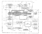
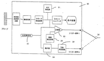
図1は本発明のX線CT装置と超音波検査装置を組み合せた血管造影計測撮影システムの一実施例の概略構成図である。 FIG. 1 is a schematic configuration diagram of an embodiment of an angiographic measurement imaging system combining an X-ray CT apparatus and an ultrasonic examination apparatus according to the present invention.
本発明のシステムはX線CT装置10、超音波検査装置30および造影剤注入装置40から構成される。
The system of the present invention includes an X-ray CT apparatus 10, an
X線CT装置10は、システム全体を統括制御するホストコンピュータ11と、X線源12、X線制御部13、X線検出器14、計測回路15などの計測部を搭載した回転盤スキャナー(図示せず)およびその回転走査を制御するスキャナ制御部19と、被検体の位置決めやらせん走査時の搬送用被検体テーブル16およびテーブル制御部17と計測データの前処理、再構成処理をはじめとした各種画像処理を実施する画像処理装置18などからなる。
The X-ray CT apparatus 10 includes a host computer 11 that performs overall control of the entire system, a rotary disk scanner (Fig. 1) equipped with an
さらに、X線CT装置10には、超音波検査装置30からのX線の曝射およびデータ計測の計測動作の開始をトリガーする外部トリガー信号を受け入れる外部信号入力部21および上記外部信号入力部21からの外部トリガー信号およびホストコンピュータ11からのX線の曝射およびデータ計測の計測動作開始をトリガーする内部トリガー信号のいづれかを選択する計測モード制御部20が設けられている。なお、本実施例では計測モードはホストコンピュータ11によって外部トリガー制御モードが選択されている。なおまた、外部トリガー信号が入力されるまでは待機状態を維持する。タイムアウト時間の設定が必要なことは言うまでもない。なおまた、トリガー信号の選択を実行する計測モード制御部20はソフトウェアで構成されてもよい。
Further, the X-ray CT apparatus 10 includes an external
X線CT装置10には、さらに血流解析部22が設けられている。超音波検査装置30は、超音波検査装置の基本構成であるプローブ、送受信回路、整相回路、Bモード検波回路、スキャンコンバータ、表示装置の他に、撮影信号の関心領域を設定するROI設定部31、信号強度の閾値を設定する閾値設定回路33、撮影信号と閾値を比較する比較器32、関心領域内の撮影信号の変化を判定する微分器34、正負判定回路35、およびトリガー信号出力部36を備えている。
The X-ray CT apparatus 10 is further provided with a blood flow analysis unit 22. The
トリガー信号出力部36はトリガー信号1あるいは2を選択的に出力する。なお、本実施例ではトリガー信号1が選択されているものとする。超音波検査装置30にはさらに血流解析装置37が設けられている。造影剤注入装置40は超音波造影剤用41とX線造影剤用42とを別々に示してあり、それぞれの注入開始は注入時間制御部43によって制御される。
The trigger
ここで、超音波検査装置による超音波造影剤の検知には、超音波反射信号の大きさの時間的変化を用いることが出来る。周知のように、造影剤からの反射信号の強度はモニタリング部位の組織や血流からの反射信号の強度よりはるかに大きいことが知られているからである。本実施例では、モニタリング部位を超音波検査装置の画面中央付近に表示させておき、そこにROIを設定し、ROI内の各画素毎の超音波反射信号強度の和を予め設定した閾値と比較する手段により、閾値より大きくなったタイミングをもってトリガー信号1としている。また、モニタリング部位を超音波検査装置の画面中央付近に表示させておき、そこにROIを設定し、例えば、ROI内の各画素毎の超音波反射信号強度の和をフレーム毎に記憶することにより、いわゆる時間濃度曲線(TDC)を求め、その勾配が正より負になるタイミングをもって上記トリガー信号2とすることもできる。これらの場合、超音波検査装置のフレーム間隔は10ms-100msの間で自由に選択できるので、フレーム間隔が0.5〜1sのCT撮影に比べて十分に時間精度がある。 Here, a temporal change in the magnitude of the ultrasonic reflection signal can be used for detection of the ultrasonic contrast agent by the ultrasonic inspection apparatus. This is because, as is well known, it is known that the intensity of the reflected signal from the contrast agent is much larger than the intensity of the reflected signal from the tissue or blood flow at the monitoring site. In this embodiment, the monitoring part is displayed near the center of the screen of the ultrasonic inspection apparatus, the ROI is set there, and the sum of the ultrasonic reflected signal intensity for each pixel in the ROI is compared with a preset threshold value. Therefore, the trigger signal 1 is set at a timing greater than the threshold. In addition, the monitoring site is displayed near the center of the screen of the ultrasonic inspection apparatus, the ROI is set there, and for example, the sum of the ultrasonic reflection signal intensity for each pixel in the ROI is stored for each frame. In other words, a so-called time density curve (TDC) is obtained, and the trigger signal 2 can be used at a timing when the gradient becomes negative from positive. In these cases, the frame interval of the ultrasonic inspection apparatus can be freely selected between 10 ms and 100 ms, so that there is sufficient time accuracy compared with CT imaging with a frame interval of 0.5 to 1 s.
超音波造影剤を用いた撮影を実施すると、図3(a),(b),(c),(d),(e)に示したように造影剤が関心領域に到達すると超音波反射信号強度が高くなり、閾値設定回路33で設定した閾値以上になると比較器32からのトリガー信号1の出力がHighとなり、閾値以下になるとLowとなる。トリガー信号2は信号強度の正負反転時、すなわち濃度変化のピークのタイミングでトリガー信号2を出力する。 When imaging using an ultrasonic contrast agent is performed, when the contrast agent reaches a region of interest as shown in FIGS. 3 (a), (b), (c), (d), and (e), an ultrasonic reflection signal is obtained. When the intensity increases and becomes equal to or higher than the threshold set by the threshold setting circuit 33, the output of the trigger signal 1 from the comparator 32 becomes High, and when the intensity becomes lower than the threshold, it becomes Low. The trigger signal 2 is output when the signal intensity is inverted, that is, at the peak timing of density change.
本実施例における外部トリガーモードによる撮影手順を、頭部造影ダイナミック造影検査を例に説明する。本実施例ではモニタリング部位を頚動脈部とした。 An imaging procedure in the external trigger mode in the present embodiment will be described by using a head contrast dynamic contrast examination as an example. In this example, the monitoring site was the carotid artery.
CT撮影に先立って、操作者がプローブを操作してモニタリング部位を映像化する。ただし、安定した映像を得られるようにセッティングした後は、撮影室の外または放射線防護壁の裏手側に移動できるように被検体に容易に着脱可能な専用プローブを用いることが操作者の被曝低減の観点から望ましい。 Prior to CT imaging, the operator operates the probe to visualize the monitoring site. However, after setting to obtain a stable image, it is possible to reduce the exposure of the operator by using a dedicated probe that can be easily attached to and detached from the subject so that it can be moved out of the imaging room or behind the radiation protection wall. From the viewpoint of.
さらに撮影開始に先立ち、操作者が撮影条件、再構成条件を設定すると、回転走査機構はスキャナを回転させ、所望の回転スピードになった段階でスキャナ制御装置19はホストコンピュータ11に撮影準備完了情報を通知する。テーブル制御部17は、らせんスキャンの場合は、あらかじめテーブル加速時間を考慮した位置に移動しておき、X線曝射開始位置で定常速度になるように制御する。ホストコンピュータ14は画像処理装置18に再構成条件に従ったパラメータを設定する。各コンポーネントの準備が完了した時点で、外部信号入力部21が有効となる。
Further, before the start of shooting, when the operator sets shooting conditions and reconstruction conditions, the rotary scanning mechanism rotates the scanner, and at the stage when the desired rotation speed is reached, the scanner control device 19 informs the host computer 11 about the shooting preparation completion information. To be notified. In the case of a helical scan, the table control unit 17 moves to a position that takes into account the table acceleration time in advance, and performs control so that the steady speed is reached at the X-ray exposure start position. The
造影剤注入器はデュアルインジェクタタイプを用い、一方には少量の超音波造影剤を、他方にはX線造影剤をセットしておく。インジェクタの造影剤注入開始ボタンを押すと、まずはじめに超音波造影剤が被検体に注入され、それに引き続きX線造影剤の注入を開始する。 The contrast agent injector uses a dual injector type, and a small amount of ultrasonic contrast agent is set on one side and an X-ray contrast agent is set on the other side. When a contrast agent injection start button of the injector is pressed, first, an ultrasonic contrast agent is injected into the subject, and subsequently, X-ray contrast agent injection is started.
静脈から注入した造影剤は、血流によって心臓に運ばれ、頚動脈を経由して関心領域である頭部に到達する。ここで図3(f),(g)に示したように、時間t0で超音波造影剤を、時間t1でX線造影剤を注入したとする。両注入の時間間隔(t1−t0)は注入時間制御部43で操作者によって設定される。モニタリング部位である頚動脈部にはまず超音波造影剤が到達し、(a)に示すような濃度変化を示す。X線造影剤は、超音波造影剤に遅れて頚動脈部に到達し(図示せず)、関心領域であるCT撮影部位にも同様に遅れて到達し、同図(b)に示した濃度変化を示す。これらの造影剤濃度変化は、それぞれ対応するX線CT装置10および超音波検査装置30では同図(c)の信号強度変化として観察することができる。ここで、超音波検査装置の信号強度が閾値Tを越えた時点t2でトリガー信号1がHighとなり、これを基準とすれば関心領域にX線造影剤が到達する時間t4までの差(t4-t2)だけX線曝射までの余裕ができるため、システム側の応答時間を考慮してもt4までには十分に撮影を開始できる。また、頚動脈から頭部関心領域までの血管経路長は静脈からの経路長に比べ短く、造影剤の循環に大きく影響する心臓などを通過した後のため、到達時間を推定するにしても被検体によるばらつきは僅かで、誤差が小さくなることが容易に推察できる。従って、t1-t0は経験的に決定する必要があるが、これはシステムの応答時間等を考慮して決定すればよい。例えば、トリガー信号出力からX線曝射t3までのタイミングが3秒とすれば、X線造影剤を超音波造影剤に4秒遅れて注入すれば、CT撮影は造影剤到達の約1秒前(頚動脈から頭部関心領域までの造影剤移動時間も含めて)から開始されることになる。
The contrast medium injected from the vein is carried by the bloodstream to the heart and reaches the head, which is the region of interest, via the carotid artery. Here, as shown in FIGS. 3F and 3G, it is assumed that an ultrasonic contrast agent is injected at time t0 and an X-ray contrast agent is injected at time t1. The time interval (t 1 -t 0) between both injections is set by the operator in the injection time control unit 43. The ultrasound contrast agent first reaches the carotid artery, which is the monitoring site, and changes in concentration as shown in (a). The X-ray contrast agent arrives at the carotid artery portion (not shown) with a delay from the ultrasound contrast agent, and similarly arrives at the CT imaging region, which is the region of interest, with the concentration change shown in FIG. Indicates. These changes in the concentration of the contrast agent can be observed as the signal intensity changes in FIG. 5C in the corresponding X-ray CT apparatus 10 and
超音波造影剤がモニタリング部位に到達し、トリガー信号がX線CT装置10に入力されると、計測モード制御部20はあらかじめ設定された遅延時間後に計測動作の開始指令を出し、CT計測が開始される。
When the ultrasound contrast agent reaches the monitoring site and a trigger signal is input to the X-ray CT apparatus 10, the measurement
撮影開始指示が出されると、ホストコンピュータ11から指示された強度のX線を対向配置されたX線検出器14に向かってX線源12から照射する。X線検出器14では被検体を透過してきたX線を検出し、固体検出器の場合はシンチレータの光をフォトダイオードで電気信号に変換した後、計測回路15でデジタルデータとして撮影データを取得する。撮影データは画像処理装置18で前処理、フィルタ処理、逆投影処理をはじめとした画像処理を施し、断層像を再構成する。再構成された画像は表示装置に表示され、診断用画像として観察者に供される。
When an imaging start instruction is issued, the X-ray having the intensity instructed from the host computer 11 is emitted from the
なお、X線撮影時に超音波造影剤がアーチファクトなどを生じさせないため、すなわち超音波検査装置による造影剤検知時刻t2直後に、1MPa以上の強力な超音波をモニタリング部位に照射して造影剤を完全に破壊するリフレッシュモードを設けてもよい。 In addition, since the ultrasound contrast agent does not cause artifacts during X-ray imaging, that is, immediately after the contrast agent detection time t2 by the ultrasonic inspection apparatus, the contrast agent is completely irradiated by irradiating the monitoring site with a strong ultrasonic wave of 1 MPa or more. A refresh mode may be provided to break down.
また、上記撮影手順を引き続いて再試する場合には、超音波造影剤が十分に排出されずに組織にトラップされている場合があるので、t0以前に上記のリフレッシュモードを付加することが望ましい。 When the imaging procedure is retried subsequently, the ultrasound contrast agent may not be sufficiently discharged and may be trapped in the tissue, so it is desirable to add the refresh mode before t0.
さらに、本実施例では、超音波検査装置30を撮影開始の指示だけでなく、X線CT装置の血流解析部23によるパーフュージョン解析の精度向上にも利用する。超音波検査装置30の血流解析部37によって頚動脈の径と流速が求められ、また前述の立ち上がりと立ち下がり間の時間(t5-t2)から通過時間が得られる。パーフュージョン解析では入力関数として動脈のTDCを超音波計測で得られた値で補償することが可能である。具体的には平均通過時間を前記通過時間で補償する。さらに、径と流速を用いて血流速CBFを補償するなどである。
Furthermore, in this embodiment, the
なお、以上の実施例では頭部パーフュージョン検査の場合で説明したが、腹部造影らせん撮影時にも本発明は応用可能であり、その際は、同様に頚動脈をモニタリング部位に用いることも可能であるが、肝臓の場合は肝動脈、門脈などをモニタリングしても良い。プローブがCT撮影断面に入ってしまうとアーチファクトの原因となる可能性があるため、プローブとしてはX線吸収計数の小さい材質をできるだけ用いるのが望ましい。 In the above embodiment, the case of the head perfusion examination has been described. However, the present invention can also be applied to abdominal contrast spiral imaging, and in that case, the carotid artery can be similarly used as a monitoring site. However, in the case of the liver, the hepatic artery, portal vein, etc. may be monitored. If the probe enters the CT imaging section, it may cause artifacts. Therefore, it is desirable to use a material having a small X-ray absorption coefficient as much as possible.
また、超音波とX線の双方でコントラスト強調可能な造影剤を用いることでより簡易なシステムを構築できる。 Moreover, a simpler system can be constructed by using a contrast agent capable of contrast enhancement with both ultrasonic waves and X-rays.
本実施例のシステムによれば、モニタリング部位へのモニタリング用超音波造影剤の到達を検出して、撮影部位へのX線造影剤の到達時間を推定し、到達時間の直前からCT撮影を開始することができるため、無効被曝を低減しながら確実にTDCを測定できる。また、撮影時間も短縮されるため、造影剤の使用量も減らすことが可能で、被験者への侵襲性も低くすることができる。さらには、超音波検査装置による測定値を用いてパーフュージョン解析の解析値を補償することで、解析精度を向上させることも可能である。 According to the system of the present embodiment, the arrival of the ultrasound contrast agent for monitoring to the monitoring site is detected, the arrival time of the X-ray contrast agent to the imaging site is estimated, and CT imaging is started immediately before the arrival time. Therefore, TDC can be reliably measured while reducing ineffective exposure. In addition, since the imaging time is shortened, the amount of contrast medium used can be reduced and the invasiveness to the subject can be reduced. Furthermore, it is possible to improve the analysis accuracy by compensating the analysis value of the perfusion analysis using the measurement value obtained by the ultrasonic inspection apparatus.
10 ・・・X線CT装置
20 ・・・計測モード制御部
21 ・・・外部信号入力部
22 ・・・血流解析部
30 ・・・超音波検査装置
36 ・・・トリガー信号出力部
37 ・・・血流解析部
40 ・・・造影剤注入装置
41 ・・・超音波造影剤注入装置
42 ・・・X線造影剤注入装置
43 ・・・注入時間制御部
10 ... X-ray CT system
20 ・ ・ ・ Measurement mode controller
21 ・ ・ ・ External signal input section
22 ・ ・ ・ Blood flow analysis unit
30 ・ ・ ・ Ultrasonic inspection equipment
36 ・ ・ ・ Trigger signal output section
37 ・ ・ ・ Blood flow analysis unit
40 ・ ・ ・ Contrast medium injection device
41 ・ ・ ・ Ultrasound contrast medium injector
42 ... X-ray contrast medium injection device
43 ・ ・ ・ Injection time controller
Claims (4)
Disposing a probe of an ultrasonic examination apparatus at a monitoring site, which is another region of interest in the vicinity of the contrast agent inflow path on the upstream side with respect to an imaging site, which is a region of interest of contrast measurement imaging of a subject by an X-ray CT apparatus; Injecting a predetermined amount of ultrasound contrast agent from a vein at a predetermined position of the subject; a predetermined time after injection of the ultrasound contrast agent; a predetermined amount of X-ray contrast agent from the vein at the predetermined position of the subject Injecting; monitoring the arrival of the ultrasound contrast agent at the monitoring site, which is another region of interest of the subject, via the probe of the ultrasonic examination apparatus, and detecting the arrival of the first trigger signal Generating and transmitting it to the X-ray CT apparatus; and, based on the first trigger signal from the ultrasonic examination apparatus, the imaging region that is the region of interest of the subject. An X-ray CT apparatus having a step of generating a second trigger signal for estimating the arrival time of the X-ray contrast agent and triggering the start of measurement and imaging of the imaging region by the X-ray CT apparatus is combined with an ultrasonic examination apparatus Angiographic measurement imaging method.
Priority Applications (1)
| Application Number | Priority Date | Filing Date | Title |
|---|---|---|---|
| JP2003304959A JP2005073764A (en) | 2003-08-28 | 2003-08-28 | System and method for angiographic measuring and imaging obtained by combining x-ray ct apparatus and ultrasonography |
Applications Claiming Priority (1)
| Application Number | Priority Date | Filing Date | Title |
|---|---|---|---|
| JP2003304959A JP2005073764A (en) | 2003-08-28 | 2003-08-28 | System and method for angiographic measuring and imaging obtained by combining x-ray ct apparatus and ultrasonography |
Publications (1)
| Publication Number | Publication Date |
|---|---|
| JP2005073764A true JP2005073764A (en) | 2005-03-24 |
Family
ID=34408505
Family Applications (1)
| Application Number | Title | Priority Date | Filing Date |
|---|---|---|---|
| JP2003304959A Pending JP2005073764A (en) | 2003-08-28 | 2003-08-28 | System and method for angiographic measuring and imaging obtained by combining x-ray ct apparatus and ultrasonography |
Country Status (1)
| Country | Link |
|---|---|
| JP (1) | JP2005073764A (en) |
Cited By (11)
| Publication number | Priority date | Publication date | Assignee | Title |
|---|---|---|---|---|
| JP2006333898A (en) * | 2005-05-31 | 2006-12-14 | Canon Inc | Radiation imaging system |
| WO2007104079A1 (en) * | 2006-03-15 | 2007-09-20 | Compumedics Limited | Ultrasound in magnetic spatial imaging apparatus |
| JP2008178466A (en) * | 2007-01-23 | 2008-08-07 | Toshiba Corp | Angiography equipment |
| JP2009022452A (en) * | 2007-07-18 | 2009-02-05 | Ge Medical Systems Global Technology Co Llc | X-ray ct system and scanning control method |
| JP2009056108A (en) * | 2007-08-31 | 2009-03-19 | Toshiba Corp | X-ray computed tomography apparatus and method |
| KR100979591B1 (en) * | 2007-07-26 | 2010-09-01 | 지이 메디컬 시스템즈 글로발 테크놀러지 캄파니 엘엘씨 | Ultrasonic Imaging Apparatus and Ultrasonic Imaging Method |
| JP2012045285A (en) * | 2010-08-30 | 2012-03-08 | Ge Medical Systems Global Technology Co Llc | Ultrasonograph and control program of the same |
| JP2013188626A (en) * | 2013-07-02 | 2013-09-26 | Toshiba Corp | X-ray ct apparatus |
| US20140121510A1 (en) * | 2011-06-20 | 2014-05-01 | Koninklijke Philips N.V. | Agent imaging |
| JP2017086152A (en) * | 2015-11-02 | 2017-05-25 | 東芝メディカルシステムズ株式会社 | X-ray computer tomography apparatus and medical diagnostic system |
| CN114420286A (en) * | 2022-01-14 | 2022-04-29 | 深圳睿心智能医疗科技有限公司 | Method and device for acquiring blood vessel physiological parameters, electronic equipment and storage medium |
-
2003
- 2003-08-28 JP JP2003304959A patent/JP2005073764A/en active Pending
Cited By (14)
| Publication number | Priority date | Publication date | Assignee | Title |
|---|---|---|---|---|
| JP2006333898A (en) * | 2005-05-31 | 2006-12-14 | Canon Inc | Radiation imaging system |
| WO2007104079A1 (en) * | 2006-03-15 | 2007-09-20 | Compumedics Limited | Ultrasound in magnetic spatial imaging apparatus |
| JP2008178466A (en) * | 2007-01-23 | 2008-08-07 | Toshiba Corp | Angiography equipment |
| JP2009022452A (en) * | 2007-07-18 | 2009-02-05 | Ge Medical Systems Global Technology Co Llc | X-ray ct system and scanning control method |
| KR100979591B1 (en) * | 2007-07-26 | 2010-09-01 | 지이 메디컬 시스템즈 글로발 테크놀러지 캄파니 엘엘씨 | Ultrasonic Imaging Apparatus and Ultrasonic Imaging Method |
| JP2009056108A (en) * | 2007-08-31 | 2009-03-19 | Toshiba Corp | X-ray computed tomography apparatus and method |
| JP2012045285A (en) * | 2010-08-30 | 2012-03-08 | Ge Medical Systems Global Technology Co Llc | Ultrasonograph and control program of the same |
| US20140121510A1 (en) * | 2011-06-20 | 2014-05-01 | Koninklijke Philips N.V. | Agent imaging |
| JP2017051629A (en) * | 2011-06-20 | 2017-03-16 | コーニンクレッカ フィリップス エヌ ヴェKoninklijke Philips N.V. | Agent imaging |
| US11166691B2 (en) * | 2011-06-20 | 2021-11-09 | Koninklijke Philips N.V. | Agent imaging |
| JP2013188626A (en) * | 2013-07-02 | 2013-09-26 | Toshiba Corp | X-ray ct apparatus |
| JP2017086152A (en) * | 2015-11-02 | 2017-05-25 | 東芝メディカルシステムズ株式会社 | X-ray computer tomography apparatus and medical diagnostic system |
| CN114420286A (en) * | 2022-01-14 | 2022-04-29 | 深圳睿心智能医疗科技有限公司 | Method and device for acquiring blood vessel physiological parameters, electronic equipment and storage medium |
| CN114420286B (en) * | 2022-01-14 | 2024-11-22 | 深圳睿心智能医疗科技有限公司 | Method, device, electronic device and storage medium for obtaining vascular physiological parameters |
Similar Documents
| Publication | Publication Date | Title |
|---|---|---|
| CN101273899B (en) | X-ray diagnostic apparatus | |
| EP0967917B1 (en) | Predictive bolus tracking | |
| CN101889872B (en) | Medical imaging apparatus and medical imaging method | |
| US6721386B2 (en) | Method and apparatus of cardiac CT imaging using ECG and mechanical motion signals | |
| CN101347339B (en) | Medical imaging diagnosis apparatus | |
| JP2007167664A (en) | Imaging device and method of operating imaging device | |
| CN102973288B (en) | X-ray image processing method | |
| Jirik et al. | Ultrasound perfusion analysis combining bolus-tracking and burst-replenishment | |
| JPS59214431A (en) | Radiation diagnostic apparatus | |
| JP2002233525A (en) | Examination of living body using image forming method | |
| JP2007021006A (en) | X-ray ct apparatus | |
| CN102711615B (en) | X-ray diagnostic apparatus, image processing apparatus and image processing program | |
| JPS59214432A (en) | Radiation diagnostic apparatus | |
| JP2005073764A (en) | System and method for angiographic measuring and imaging obtained by combining x-ray ct apparatus and ultrasonography | |
| WO2009077914A1 (en) | Method and system for imaging | |
| JP5534703B2 (en) | X-ray diagnostic equipment | |
| JP5886581B2 (en) | Vascular plaque diagnostic imaging system | |
| JP6100910B2 (en) | Information processing apparatus, photographing system, information processing method, and program | |
| JPH0759781A (en) | Ultrasonic diagnostic equipment | |
| JP6595434B2 (en) | Drug imaging | |
| CN115844435A (en) | Perfusion imaging | |
| US7379532B2 (en) | ECG-based rotational angiography for cardiology | |
| JP4612325B2 (en) | Ultrasonic diagnostic equipment | |
| Jiřík et al. | Parametric ultrasound perfusion analysis combining bolus tracking and replenishment | |
| JP2005224459A (en) | Medical image diagnostic system, x-ray image diagnostic device and contrast medium injector |