JP2005073742A - Game machine - Google Patents

Game machine Download PDF

Info

Publication number
JP2005073742A
JP2005073742A JP2003304631A JP2003304631A JP2005073742A JP 2005073742 A JP2005073742 A JP 2005073742A JP 2003304631 A JP2003304631 A JP 2003304631A JP 2003304631 A JP2003304631 A JP 2003304631A JP 2005073742 A JP2005073742 A JP 2005073742A
Authority
JP
Japan
Prior art keywords
symbol
game
board
ball
unit
Prior art date
Legal status (The legal status is an assumption and is not a legal conclusion. Google has not performed a legal analysis and makes no representation as to the accuracy of the status listed.)
Pending
Application number
JP2003304631A
Other languages
Japanese (ja)
Other versions
JP2005073742A5 (en
Inventor
Kazuhiro Kuromiya
和広 黒宮
Current Assignee (The listed assignees may be inaccurate. Google has not performed a legal analysis and makes no representation or warranty as to the accuracy of the list.)
Sanyo Bussan Co Ltd
Original Assignee
Sanyo Bussan Co Ltd
Priority date (The priority date is an assumption and is not a legal conclusion. Google has not performed a legal analysis and makes no representation as to the accuracy of the date listed.)
Filing date
Publication date
Application filed by Sanyo Bussan Co Ltd filed Critical Sanyo Bussan Co Ltd
Priority to JP2003304631A priority Critical patent/JP2005073742A/en
Publication of JP2005073742A publication Critical patent/JP2005073742A/en
Publication of JP2005073742A5 publication Critical patent/JP2005073742A5/ja
Pending legal-status Critical Current

Links

Images

Landscapes

  • Pinball Game Machines (AREA)

Abstract

<P>PROBLEM TO BE SOLVED: To provide a game machine suppressing a fraud relative to a control board in the game machine such as a Pachinko machine and a slot machine. <P>SOLUTION: This game machine is associated with an operation of cutting a sealing member of a part fixed with screws and removing a board box from a mount, detects the disconnection of a circuit pattern to be cut by a disconnection detector 409 and stores the detection signal in a first storage part 410 provided in a display control device 45. Information stored in the first storage device 410 is arbitrarily displayed on a first symbol display device 42, compares it with a history individually recorded for every removal of the board box 263 or the number of parts cutting the sealing members and precisely determines how many times the board boxes 263 are removed. <P>COPYRIGHT: (C)2005,JPO&NCIPI

Description

この発明は、パチンコ機やスロットマシン等の遊技機に関する。   The present invention relates to a gaming machine such as a pachinko machine or a slot machine.

従来、遊技機の代表としてパチンコ機がある。このパチンコ機では、遊技状態を様々な状態に制御するための複数の制御基板が設けられている。これら制御基板は、パチンコ機本体の裏面側に着脱可能に取り付けられている(例えば、特許文献1参照)。
特開平2000−24262号公報(図2〜図4)
Conventionally, there is a pachinko machine as a representative of the gaming machine. This pachinko machine is provided with a plurality of control boards for controlling the gaming state to various states. These control boards are detachably attached to the back side of the main body of the pachinko machine (for example, see Patent Document 1).
JP 2000-24262 A (FIGS. 2 to 4)

しかしながら、このような構成を有する従来例の場合には、次のような問題がある。   However, the conventional example having such a configuration has the following problems.

すなわち、従来のパチンコ機では、これら制御基板を収容する収容体が簡単な操作で着脱可能に取り付けられているため、不正な制御基板に容易に交換されてしまう恐れがある。   That is, in the conventional pachinko machine, since the container for housing these control boards is detachably attached by a simple operation, there is a possibility that the control board is easily replaced with an unauthorized control board.

本発明は、このような事情に鑑みてなされたものであって、制御基板に対する不正を抑止することのできる遊技機を提供することを主たる目的とする。   The present invention has been made in view of such circumstances, and it is a main object of the present invention to provide a gaming machine capable of suppressing fraud with respect to a control board.

この発明は、このような目的を達成するために、次のような構成をとる。   In order to achieve such an object, the present invention has the following configuration.

すなわち、請求項1に記載の発明は、遊技機本体の裏面側に台座部材を有し、この台座部材を介して遊技状態を制御する制御手段を収容する収容体を遊技機本体の裏面側に着脱可能に搭載した遊技機において、
前記台座部材における収容体の着脱状態を検出する検出手段と、
前記検出手段からの検出結果を記憶する記憶手段と、
前記記憶手段に記憶された検出結果を表示する表示手段と
を備えたことを特徴とするものである。
That is, the invention according to claim 1 has a pedestal member on the back side of the gaming machine main body, and a container for housing the control means for controlling the gaming state via the pedestal member is provided on the back side of the gaming machine main body. In a game machine that is detachably mounted,
Detecting means for detecting the attachment / detachment state of the container in the pedestal member;
Storage means for storing detection results from the detection means;
And a display means for displaying the detection result stored in the storage means.

[作用・効果] 請求項1に記載の発明によれば、検出手段は、台座部材における収容体の着脱状態を検出する。記憶手段は、検出手段が検出した収容体の着脱状態を記憶する。表示手段は、記憶手段に記憶された収容体の着脱状態を表示出力する。つまり、台座部材から収容体が取り外された状態が検出手段により検出され、その検出結果が記憶手段に記憶される。したがって、記憶手段に記憶された結果を表示手段に表示することにより収容体が取り外されたことを確認することができる。   [Operation / Effect] According to the invention described in claim 1, the detecting means detects the attachment / detachment state of the container in the base member. The storage means stores the attachment / detachment state of the container detected by the detection means. The display means displays and outputs the attachment / detachment state of the container stored in the storage means. That is, the state in which the container is removed from the pedestal member is detected by the detection means, and the detection result is stored in the storage means. Therefore, it is possible to confirm that the container has been removed by displaying the result stored in the storage unit on the display unit.

例えば、記憶手段は、収容体を取り外した回数を記憶し、表示手段は、その記憶された取り外し回数を表示する。遊技機を管理する側では、表示手段に表示された回数と、自らが管理している収容体の取り外し回数の履歴とが相違していれば、制御手段が交換されるなどの不正行為を知ることがき、結果、制御手段に対する不正を抑止することができる。   For example, the storage means stores the number of times the container has been removed, and the display means displays the stored number of removals. If the number of times displayed on the display means and the history of the number of removals of the container managed by the gaming machine are different, the game machine management side knows illegal acts such as replacement of the control means. As a result, fraud to the control means can be suppressed.

なお、本明細書は、次のような遊技機に係る発明も開示している。   The present specification also discloses an invention relating to the following gaming machines.

(1) 請求項1に記載の遊技機において、
さらに、前記収容体を固定して開放を規制する固定手段を備え、
前記検出手段は、固定手段の固定解除操作に連動して台座部材からの収容体の取り外しを検出することを特徴とする遊技機。
(1) In the gaming machine according to claim 1,
Furthermore, a fixing means for fixing the container and restricting the opening is provided,
The game machine according to claim 1, wherein the detection means detects the removal of the container from the base member in conjunction with the fixing release operation of the fixing means.

前記(1)に記載の発明によれば、固定手段は、制御手段が収容された収容体の開放を規制する。検出手段は、固定手段の固定解除操作に連動して台座部材から収容体の取り外しを検出する。したがって、固体手段の固定解除操作を行ったことが検出手段により検出されて記憶手段に記憶される、結果、請求項1に記載の遊技機を好適に実施することができる。   According to the invention as described in said (1), a fixing means regulates opening | releasing of the accommodating body in which the control means was accommodated. The detection means detects the removal of the container from the pedestal member in conjunction with the fixing release operation of the fixing means. Therefore, it is detected by the detection means that the operation of releasing the fixation of the solid means is performed and stored in the storage means. As a result, the gaming machine according to claim 1 can be suitably implemented.

(2) 請求項1および前記(1)に記載の遊技機において、
前記検出手段は、前記台座部材からの収容体の着脱状態を電気的な通電状態または断線状態として検出することを特徴とする遊技機。
(2) In the gaming machine according to claim 1 and (1),
The game machine according to claim 1, wherein the detecting means detects an attachment / detachment state of the container from the pedestal member as an electrically energized state or a disconnected state.

前記(2)に記載の発明によれば、検出手段は、台座部材からの収容体の着脱状態を電気的な通電状態または断線状態として検出することが好ましい。このように構成することにより、電気的な変化を検出し、その情報を容易に記憶手段に記憶することができる。したがって、請求項1に記載の遊技機を好適に実施することができる。   According to the invention as described in said (2), it is preferable that a detection means detects the attachment or detachment state of the container from a base member as an electrical conduction state or a disconnection state. By comprising in this way, an electrical change is detected and the information can be easily memorize | stored in a memory | storage means. Therefore, the gaming machine according to claim 1 can be suitably implemented.

(3) 前記(1)または(2)に記載の遊技機において、
前記検出手段は、前記台座部材からの収容体の取り外しに連動して電気的接続状態のオン・オフ切り替えを行うスイッチであることを特徴とする遊技機。
(3) In the gaming machine according to (1) or (2),
The gaming machine according to claim 1, wherein the detecting means is a switch for switching on and off an electrical connection state in conjunction with the removal of the container from the pedestal member.

前記(3)に記載の発明によれば、検出手段として、収容体の取り外しに連動して電気的接続状態のオン・オフ切り替えを行うスイッチであることが好ましい。   According to the invention as described in said (3), it is preferable that it is a switch which switches on / off of an electrical connection state in conjunction with removal of a container as a detection means.

(4) 前記(1)または(2)のいずれかに記載の遊技機において、
前記台座部材と収容体を固定する固定手段は、台座部材および収容体における複数個の固定部分の少なくとも1箇所を固定し、
前記各固定部分には、電気的に通電する回路パターンが形成されており、
前記固定手段の固定解除操作に連動して前記回路パターンが断線されるように構成したことを特徴とする遊技機。
(4) In the gaming machine according to either (1) or (2),
The fixing means for fixing the pedestal member and the container is configured to fix at least one of a plurality of fixed portions in the pedestal member and the container,
Each of the fixed portions is formed with a circuit pattern that is electrically energized,
A gaming machine configured so that the circuit pattern is disconnected in conjunction with a fixing release operation of the fixing means.

前記(4)に記載の発明によれば、固定手段は、台座部材と収容体における複数箇所の固定部分のうち少なくなくとも1箇所を固定する。また、収容体に対する固定手段の固定部分に電気的に通電する回路パターンが形成されている。つまり、固定手段の固定解除操作に連動して回路パターンが断線される。したがって、固定手段を解除しようとするとき、回路パターンが断線し、この断線状態が検出手段により検出されて記憶手段に記憶される。したがって、前記(1)または(2)に記載の遊技機を好適に実施することできる。   According to the invention as described in said (4), a fixing means fixes at least 1 place among the fixing parts of the multiple places in a base member and a container. In addition, a circuit pattern for electrically energizing the fixing portion of the fixing means for the container is formed. That is, the circuit pattern is disconnected in conjunction with the fixing release operation of the fixing means. Therefore, when the fixing means is to be released, the circuit pattern is disconnected, and this disconnection state is detected by the detection means and stored in the storage means. Therefore, the gaming machine described in the above (1) or (2) can be suitably implemented.

(5) 前記(1)ないし(4)のいずれかに記載の遊技機において、
始動条件の成立により識別変動表示の実行を制御する表示制御手段に前記記憶手段を備えたことを特徴とする遊技機。
(5) In the gaming machine according to any one of (1) to (4),
A gaming machine characterized in that the storage means is provided in display control means for controlling execution of identification variation display when a start condition is established.

前記(5)に記載の発明によれば、記憶手段に表示制御手段を備えることが好ましい。例えば、制御手段に対して不正行為が行われる場合、制御手段自体を不正なものに交換して再度遊技機に組み込まれる。したがって、制御手段に記憶手段を備えておくと、記憶手段に記憶されている情報自体が変更されるおそれがある。しかしながら、通常、制御手段とは個別に配備される表示制御手段に記憶手段を備えておくことにより、記憶手段に記憶された収容体の取り外された情報は、制御手段側から直接に操作して情報の変更などを行うことができない。   According to the invention as described in said (5), it is preferable to provide a display control means in a memory | storage means. For example, when a fraudulent act is performed on the control means, the control means itself is exchanged for an unauthorized one and is incorporated into the gaming machine again. Therefore, if the storage means is provided in the control means, the information stored in the storage means may be changed. However, usually, the display control means provided separately from the control means is provided with a storage means, so that the removed information stored in the storage means can be operated directly from the control means side. Information cannot be changed.

したがって、記憶手段に記憶された情報を適正に保持することができ、制御手段に対する不正行為をより一層に抑止することができる。なお、本明細書中の「識別情報」とは、数字図柄、絵図柄またはそれらを組み合わせた図柄などであって、特別遊技状態への移行の成立・不成立を遊技者に視覚を通じて認識させるための表示情報のことである。   Therefore, the information stored in the storage unit can be properly held, and illegal acts on the control unit can be further suppressed. The “identification information” in this specification is a numerical symbol, a graphic symbol, or a combination of these, and is used to allow the player to visually recognize the success or failure of the transition to the special gaming state. It is display information.

また、通常、収容体を台座部材から取り外す際、着脱および開放を規制する固定手段を残したままの状態で、収容体側の固定部分を破壊しなければならないようになっている。したがって、台座部材から収容体を取り外した回数を、収容体の固定部分の破壊された個数をカウントすれば確認することができる。つまり、破壊された固定部分の個数と、表示制御手段内に備えられた記憶手段に記憶された収容体の取り外された回数とを比較することにより、収容体が取り外されて制御手段に不正行為が行われたか否かを容易に判定することができるようになる。その結果、制御手段に対する不正を抑止するのに好適である。   Moreover, normally, when removing a container from a base member, the fixing | fixed part by the side of a container must be destroyed in the state which left the fixing means which controls attachment or detachment. Therefore, the number of times the container is removed from the base member can be confirmed by counting the number of broken fixed portions of the container. That is, by comparing the number of fixed parts destroyed and the number of times the container is removed stored in the storage means provided in the display control means, the container is removed and the control means is illegally operated. It becomes possible to easily determine whether or not the operation has been performed. As a result, it is suitable for suppressing fraud with respect to the control means.

(6) 前記(1)ないし(4)に記載の遊技機において、
遊技場内に配設された複数台の遊技機を総括的に制御するホストコンピュータに前記記憶手段を備えたことを特徴とする遊技機。
(6) In the gaming machine according to (1) to (4),
A gaming machine comprising a host computer that comprehensively controls a plurality of gaming machines arranged in a game hall, the storage means being provided.

前記(6)に記載の発明によれば、ホストコンピュータに記憶手段を備えることが好ましい。例えば、制御手段に対して不正行為を行う場合、制御手段自体を不正のものに交換して再度遊技機に組み込まれる。したがって、制御手段に記憶手段を設けておくと、記憶手段に記憶されている情報自体が変更されるおそれがある。しかしながら、ホストコンピュータに記憶手段に備えておくことにより、記憶手段に記憶された収容体の取り外された情報は、遊技機側の制御手段から直接に操作して情報の変更などを行うことができない。したがって、記憶手段の情報を適正に保持することができ、制御手段に対する不正をより確実に抑止することができる。   According to the invention as described in said (6), it is preferable to provide a memory | storage means in a host computer. For example, when an illegal act is performed with respect to the control means, the control means itself is replaced with an illegal one and is incorporated into the gaming machine again. Therefore, if the storage means is provided in the control means, the information stored in the storage means may be changed. However, by providing the storage means in the host computer, the information removed from the container stored in the storage means cannot be changed directly by operating the control means on the gaming machine side. . Therefore, the information in the storage unit can be properly held, and fraud to the control unit can be more reliably suppressed.

また、通常、収容体を台座部材から取り外す際に、着脱および開放を規制する固定手段を残したままの状態で、収容体側の固定部分を破壊しなければならないようになっている。したがって、台座部材から収容体を取り外した回数を、収容体の固定部分の破壊された個数をカウントすれば確認することができる。つまり、破壊された固定部分の個数と、ホストコンピュータに備えられた記憶手段に記憶された収容体の取り外された回数とを比較することにより、収容体が取り外されて制御手段に不正行為が行われたか否かを容易に判定することができるようになる。その結果、制御手段に対する不正を抑止するのに好適である。   Moreover, normally, when removing a container from a base member, the fixing | fixed part by the side of a container must be destroyed in the state which left the fixing means which controls attachment or detachment. Therefore, the number of times the container is removed from the base member can be confirmed by counting the number of broken fixed portions of the container. In other words, by comparing the number of the fixed parts destroyed and the number of times the container is removed stored in the storage means provided in the host computer, the container is removed and the control means performs an illegal act. It becomes possible to easily determine whether or not it has been broken. As a result, it is suitable for suppressing fraud with respect to the control means.

さらに、ホストコンピュータに記憶手段を備えることにより、遊技場内に配設した複数台の遊技機の状態を総括的に管理することができ、効率よく不正を抑止することができる。   Furthermore, by providing storage means in the host computer, it is possible to comprehensively manage the state of a plurality of gaming machines arranged in the game arcade, and to prevent fraud efficiently.

(7) 前記(1)ないし(6)のいずれかに記載の遊技機において、
前記表示手段は、前記表示制御手段の制御に応じて識別変動表示の変動表示を行う第1図柄表示装置であることを特徴とする遊技機。
(7) In the gaming machine according to any one of (1) to (6),
The gaming machine according to claim 1, wherein the display means is a first symbol display device that performs a variation display of the identification variation display in accordance with the control of the display control means.

前記(7)に記載の発明によれば、表示手段は、始動条件が成立したときに表示制御手段の制御により識別変動表示の変動表示を行う第1図柄表示装置でることが好ましい。このように記憶手段に記憶された結果(情報)を第1図柄表示装置に表示することにより、遊技機の前面側から収容体の着脱した履歴を容易に確認することができる。例えば、管理者側が所定の遊技機の収容体を着脱した履歴(例えば回数や日時)を記録しておくことにより、遊技機の裏面側から収容体に収容された制御手段の状態を確認せずとも、第1図柄表示装置に表示される履歴と比較することで、制御手段に対して不正を行ったか否かを容易に確認することができる。その結果、制御手段に対する不正を抑止するの好適である。   According to the invention as described in said (7), it is preferable that a display means is a 1st symbol display apparatus which performs the fluctuation display of an identification fluctuation display by control of a display control means, when starting conditions are satisfied. By displaying the result (information) stored in the storage means on the first symbol display device in this way, it is possible to easily confirm the history of detachment of the container from the front side of the gaming machine. For example, by recording the history (for example, the number of times and the date and time) that the administrator side attached / detached the container of a predetermined gaming machine, the state of the control means accommodated in the container is not confirmed from the back side of the gaming machine In both cases, by comparing with the history displayed on the first symbol display device, it is possible to easily confirm whether or not the control means has been cheated. As a result, it is preferable to suppress fraud with respect to the control means.

(8) 前記(1)ないし(6)のいずれかに記載の遊技機において、
前記表示手段は、前記記憶手段に記憶された結果のみを表示するための表示手段であることを特徴とする遊技機。
(8) In the gaming machine according to any one of (1) to (6),
The gaming machine, wherein the display means is a display means for displaying only a result stored in the storage means.

前記(8)に記載の発明によれば、表示手段は、記憶手段に記憶された結果(情報)のみをを表示するものである。換言すれば、第1図柄表示装置とは個別に検出結果を表示する専用の表示手段であり、検出結果のみを容易に表示出力することができる。   According to the invention as described in said (8), a display means displays only the result (information) memorize | stored in the memory | storage means. In other words, the first symbol display device is a dedicated display means for individually displaying the detection result, and only the detection result can be easily displayed and output.

なお、この表示手段の配備位置は、遊技機の前面側であって、遊技者の視認できる箇所または視認できない箇所のいずれであってもよい。例えば、視認できる箇所にこの表示手段を配備することにより、遊技者が検出結果を確認することができるので、制御手段に対する不正を抑止するのに好適である。   It should be noted that the position where the display means is provided may be either on the front side of the gaming machine, where the player can see or where the player cannot see. For example, by arranging this display means at a place where it can be visually recognized, the player can confirm the detection result, which is suitable for suppressing fraud with respect to the control means.

(9) 前記(8)に記載の遊技機において、
前記記憶手段は、制御手段または前記表示制御手段の少なくともいずれかに備えた遊技機用記憶手段と、前記ホストコンピュータに備えたホスト用記憶手段とから構成され、
さらに、ホストコンピュータは、遊技機用記憶手段とホスト用記憶手段とに記憶された検出結果を比較する比較手段を備えたことを特徴とする遊技機。
(9) In the gaming machine according to (8),
The storage means comprises a gaming machine storage means provided in at least one of the control means and the display control means, and a host storage means provided in the host computer,
The host computer further comprises a comparison means for comparing the detection results stored in the gaming machine storage means and the host storage means.

前記(9)に記載の発明によれば、記憶手段を遊技機側の制御手段または表示制御手段の少なくともいずれかと、遊技場内に配設した複数台の遊技機を総括的に制御・管理するホストコンピュータの複数箇所に設けるのが好ましい。つまり、ホストコンピュータ側に備えた比較手段により、遊技機側の遊技機用記憶手段とホストコンピュータ側のホスト用記憶手段の両方に記憶された検出結果を比較することができる。したがって、結果の一致または不一致から収容体が台座部材から取り外されて制御手段に不正行為が行われたことなどをより正確に判定することができる。その結果、制御手段に対する不正をより一層に抑止することができる。   According to the invention described in (9) above, the host that controls and manages the storage unit as a whole and at least one of the control unit or the display control unit on the gaming machine side and a plurality of gaming machines arranged in the game hall It is preferable to provide at a plurality of locations of the computer. That is, the comparison result provided on the host computer side can compare the detection results stored in both the gaming machine storage unit on the gaming machine side and the host storage unit on the host computer side. Therefore, it is possible to more accurately determine that the container has been removed from the base member due to the coincidence or inconsistency of the results and that the control means has been cheated. As a result, fraud with respect to the control means can be further suppressed.

(10) 前記(1)ないし(9)のいずれかに記載の遊技機において、
さらに、前記収容体が台座部材に取り付けられた場合に前記検出手段と通電状態を維持するとともに、前記記憶手段が常時作動するようにそれぞれに電力を供給する電力供給手段を備えたことを特徴とする遊技機。
(10) In the gaming machine according to any one of (1) to (9),
Furthermore, when the container is attached to a pedestal member, the detection means is maintained in an energized state, and further provided with power supply means for supplying power to each of the storage means so as to always operate. To play.

前記(10)に記載の発明によれば、電力供給手段は、台座部材に収容体が取り付けられた場合に検出手段と通電状態を維持するとともに、記憶手段が常時作動するようそれぞれに電力を供給する。一般に遊技場の営業時間が終了すると、各遊技機への電力供給が停止されて非動作状態となる。また、制御手段に対する不正行為が行われる時間帯が営業時間終了した閉店後である。つまり、閉店後に遊技機の所定の機能が作動していなければ、収容体が台座部材から取り外されたことを電気的に検出することができない。   According to the invention described in (10) above, the power supply means maintains the energized state with the detection means when the container is attached to the pedestal member, and supplies power to the storage means so that it always operates. To do. Generally, when the business hours of the game hall are over, the power supply to each gaming machine is stopped and the game machine becomes non-operating. In addition, the time period during which fraudulent acts on the control means are performed is after the store is closed. That is, if the predetermined function of the gaming machine is not activated after the store is closed, it cannot be electrically detected that the container has been removed from the base member.

したがって、電力供給手段により検出手段および記憶手段に電力供給が常時行われていることにより、常に収容体が台座部材から取り外されたことを検出手段が電気的に検出し、その結果を記憶手段が記憶することができる。したがって、遊技機の制御手段の状態を終日監視することができ、制御手段に対する不正をより確実に抑止することができる。   Therefore, by constantly supplying power to the detection means and the storage means by the power supply means, the detection means always detects that the container has been removed from the pedestal member, and the storage means Can be remembered. Therefore, the state of the control means of the gaming machine can be monitored throughout the day, and fraud to the control means can be more reliably suppressed.

(11) 請求項1に記載の遊技機、または、前記(1)ないし(10)のいずれかに記載の遊技機において、
左右一側部側を中心に左右他側部側が開閉可能となるように構成され、遊技盤を支持した遊技機本体と、
前記遊技盤の前面に設けられたレール部材により略円形状に区画された遊技領域と、
前記遊技機本体の前面側にて前記左右一側部側を中心に前記左右他側部が開閉可能となるように支持され、閉鎖状態において前記遊技領域を視認可能な視認窓を有した前面扉とを備え、
前記遊技機本体の前記左右一側部には長尺状の補強部材を上下方向へ延びるように設けられるとともに、前記遊技機本体の前記左右他側部には前記遊技機本体及び前面扉の開放を禁止するように旋錠する旋錠装置を設け、
該旋錠装置は前記遊技機本体の前記左右他側部に上下方向へ延びるようにかつ上下方向へ移動可能となるように設けられた長尺状の連動部材と、前記遊技機本体の前記左右他側部のうち前記遊技領域の最大幅となる位置とは異なる位置に設けられ前記連動部材を上側又は下側への移動により前記遊技機本体の旋錠が解除されるとともに、前記連動部材の上下他方への移動により前記前面扉の旋錠が解除されるように構成し、
前記遊技盤を前記遊技機本体の幅内において前記補強部材及び連動部材を左右に振り分けて配置するための領域を残した幅となるように形成するとともに、前記遊技盤の左右両側部には前記遊技機本体の左右両側からの張出領域との干渉を回避するように部分的に凹部を形成し、さらに、前記区画部材のうち、前記遊技領域の最大幅となる位置を、前記遊技盤の左右端位置に至るように配設することにより、遊技領域を拡張したことを特徴とする遊技機。
(11) In the gaming machine according to claim 1, or the gaming machine according to any one of (1) to (10),
A gaming machine main body configured to be openable and closable on the left and right other side with the left and right one side as the center, and a gaming board,
A game area partitioned in a substantially circular shape by a rail member provided on the front surface of the game board;
A front door having a viewing window that is supported on the front side of the gaming machine main body so that the left and right other side parts can be opened and closed with the left and right side parts as the center, and in which the gaming area can be seen in the closed state. And
A long reinforcing member is provided on the left and right sides of the gaming machine main body so as to extend in the vertical direction, and the gaming machine main body and the front door are opened on the left and right other sides of the gaming machine main body. Provided a locking device that locks to prohibit
The locking device includes a long interlocking member provided on the other left and right sides of the gaming machine body so as to extend in the vertical direction and to be movable in the vertical direction, and the left and right other parts of the gaming machine body. The side of the gaming machine main body is unlocked by moving the interlocking member upward or downward provided at a position different from the position of the maximum width of the gaming area of the side portion, and the upper and lower other of the interlocking member Configured to unlock the front door by moving to
The game board is formed to have a width that leaves a region for arranging the reinforcing member and the interlocking member to be distributed to the left and right within the width of the gaming machine main body. A recess is partially formed so as to avoid interference with the overhanging area from the left and right sides of the gaming machine main body, and further, the position of the partition member that is the maximum width of the gaming area is defined on the gaming board. A gaming machine characterized by extending a gaming area by being arranged so as to reach left and right end positions.

前記(11)に記載の発明によれば、遊技盤の左右両側部は、遊技機本体の左右両側からの張出領域との干渉を回避するように部分的に凹部を形成している。区画部材のうち遊技領域の最大幅となる位置を、遊技盤の左右端位置に至るように配設する。したがって、遊技領域が広くなり、大きい区画部材を用いた場合においても、遊技球を安定した状態で遊技領域に運ぶことができる。その結果、遊技球が遊技領域において、興趣性の向上を図ることができる。   According to the invention described in (11) above, the left and right side portions of the game board are partially recessed so as to avoid interference with the overhanging regions from the left and right sides of the gaming machine main body. The position which becomes the maximum width | variety of a game area among division members is arrange | positioned so that the left-right end position of a game board may be reached. Therefore, the game area is widened, and even when a large partition member is used, the game ball can be transported to the game area in a stable state. As a result, it is possible to improve the interest of the game ball in the game area.

(12) 請求項1に記載の遊技機、または、前記(1)ないし(11)のいずれかに記載の遊技機において、
前記遊技機はパチンコ機であることを特徴とする遊技機。
(12) In the gaming machine according to claim 1, or the gaming machine according to any one of (1) to (11),
The gaming machine is a pachinko machine.

前記(12)に記載の遊技機によれば、興趣性に優れたパチンコ機を提供できる。なお、パチンコ機の基本構成としては操作ハンドルを備え、その操作ハンドルの操作に応じて遊技用媒体としての球を所定の遊技領域に発射し、球が遊技領域内の所定の位置に配設された作動口に入賞(または作動ゲートを通過)することを必要条件として、表示装置において動的表示されている識別情報(図柄等)が所定時間後に確定停止されるものが挙げられる。また、特別遊技状態の発生時には、遊技領域内の所定の位置に配設された可変入賞手段(特定入賞口)が所定の態様で開放されて球を入賞可能とし、その入賞個数に応じた有価価値(景品球のみならず、磁気カードへ書き込まれるデータ等も含む)が付与されるものが挙げられる。   According to the gaming machine described in (12) above, it is possible to provide a pachinko machine with excellent interest. The basic configuration of the pachinko machine is provided with an operation handle, and a ball as a game medium is launched into a predetermined game area in accordance with the operation of the operation handle, and the ball is disposed at a predetermined position in the game area. In other words, the identification information (such as symbols) that is dynamically displayed on the display device is determined and stopped after a predetermined time on the condition that a winning (or passing through the operation gate) is required. In addition, when a special gaming state occurs, variable winning means (specific winning opening) arranged at a predetermined position in the gaming area are opened in a predetermined manner so that a ball can be won, and a value corresponding to the number of winnings can be obtained. Examples include those to which value (including data written on a magnetic card as well as premium spheres) is given.

(13) 請求項1に記載の遊技機、または、前記(1)ないし(11)のいずれかに記載の遊技機において、
前記遊技機はスロットマシンであることを特徴とする遊技機。
(13) In the gaming machine according to claim 1, or the gaming machine according to any one of (1) to (11),
The gaming machine is a slot machine.

前記(13)に記載の遊技機によれば、興趣性に優れたスロットマシンを提供できる。なお、スロットマシンの基本構成としては、「複数の識別情報からなる識別情報列を動的表示した後に識別情報を確定表示する可変表示手段を備え、始動用操作手段(例えば操作レバー)の操作に起因して識別情報の動的表示が開始され、停止用操作手段(例えばストップボタン)の操作に起因して、あるいは、所定時間経過することにより、識別情報の動的表示が停止され、その停止時の確定識別情報が特定識別情報であることを必要条件として、遊技者に有利な特別遊技状態を発生させる特別遊技状態発生手段とを備えた遊技機」となる。この場合、遊技用媒体はコイン、メダル等が代表例として挙げられる。   According to the gaming machine described in (13) above, it is possible to provide a slot machine with excellent interest. The basic configuration of the slot machine is “variable display means for confirming and displaying the identification information after dynamically displaying an identification information string composed of a plurality of identification information, and for operating the starting operation means (for example, an operation lever). As a result, the dynamic display of the identification information is started, and the dynamic display of the identification information is stopped due to the operation of the operation means for stop (for example, the stop button) or when a predetermined time elapses. The game machine is provided with special game state generating means for generating a special game state advantageous to the player on the condition that the confirmed identification information at that time is the specific identification information. In this case, a typical example of the game medium is a coin, a medal or the like.

(14) 請求項1に記載の遊技機、または、前記(1)ないし(11)のいずれかに記載の遊技機において、
前記遊技機はパチンコ機とスロットマシンとを融合させたものであることを特徴とする遊技機。
(14) In the gaming machine according to claim 1, or the gaming machine according to any one of (1) to (11),
The gaming machine is a combination of a pachinko machine and a slot machine.

前記(14)に記載の遊技機によれば、興趣性に優れた、パチンコ機とスロットマシンとを融合させたものを提供できる。なお、この融合させたものの基本構成としては、「複数の識別情報からなる識別情報列を動的表示した後に識別情報を確定表示する識別情報変動表示手段を備え、始動用操作手段(例えば操作レバー)の操作に起因して識別情報の動的表示が開始され、停止用操作手段(例えばストップボタン)の操作に起因して、あるいは、所定時間経過することにより、識別情報の動的表示が停止され、その停止時の確定識別情報が特定識別情報であることを必要条件として、遊技者に有利な特別遊技状態を発生させる特別遊技状態発生手段とを備え、遊技用媒体として球を使用するとともに、前記識別情報の動的表示の開始に際しては所定数の球を必要とし、特別遊技状態の発生に際しては多くの球が払い出されるように構成されている遊技機」となる。   According to the gaming machine described in the above (14), it is possible to provide a fusion of a pachinko machine and a slot machine that is excellent in interest. The basic configuration of the merged component is “including an identification information variation display means for confirming and displaying the identification information after dynamically displaying an identification information sequence composed of a plurality of identification information, and a starting operation means (for example, an operation lever). The dynamic display of the identification information is started due to the operation of), and the dynamic display of the identification information is stopped due to the operation of the operation means for stopping (for example, the stop button) or after a predetermined time has elapsed. And a special game state generating means for generating a special game state advantageous to the player on the condition that the confirmed identification information at the time of the stop is specific identification information, and using a ball as a game medium A gaming machine is configured so that a predetermined number of balls are required at the start of dynamic display of the identification information, and many balls are paid out when a special gaming state occurs.

この発明に係る遊技機によれば、台座部材に取り付けられた収容体の着脱状態を検出手段で検出し、この検出結果を記憶手段に記憶しておくことにより、収容体が取り外された回数などの履歴を確認することができるとともに、取り外しにともなう制御手段に対する不正行為を未然に抑止することができる。   According to the gaming machine according to the present invention, the number of times the container has been removed by detecting the attachment / detachment state of the container attached to the base member by the detection means and storing the detection result in the storage means. Can be confirmed, and fraudulent acts on the control means associated with the removal can be prevented in advance.

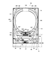
以下、パチンコ遊技機(以下、単に「パチンコ機」という)の一実施の形態を、図面に基づいて詳細に説明する。図1はパチンコ機10の正面図であり、図2は、外枠11に対して内枠12と前面枠セット14とを開放した状態を示す斜視図である。但し、図2では便宜上、下皿ユニット13が内枠12から取り外された状態を示している。   Hereinafter, an embodiment of a pachinko gaming machine (hereinafter simply referred to as a “pachinko machine”) will be described in detail with reference to the drawings. FIG. 1 is a front view of the pachinko machine 10, and FIG. However, FIG. 2 shows a state in which the lower plate unit 13 is removed from the inner frame 12 for convenience.

図1,2に示すように、パチンコ機10は、当該パチンコ機10の外殻を形成する外枠11と、この外枠11の一側部に開閉可能に支持された内枠12とを備えている。以下に、外枠11と内枠12との構成を個別に詳細に説明する。   As shown in FIGS. 1 and 2, the pachinko machine 10 includes an outer frame 11 that forms an outer shell of the pachinko machine 10, and an inner frame 12 that is supported on one side of the outer frame 11 so as to be openable and closable. ing. Below, the structure of the outer frame 11 and the inner frame 12 is demonstrated in detail separately.

外枠11は、木製の板材により全体として矩形状に構成され、小ネジ等の離脱可能な締結具により各板材が組み付けられている。本実施の形態では、外枠11の上下方向の外寸は809mm(内寸771mm)、左右方向の外寸は518mm(内寸480mm)となっている。なお、外枠11は樹脂やアルミニウム等の軽金属により構成されていてもよい。   The outer frame 11 is formed in a rectangular shape as a whole by a wooden plate material, and each plate material is assembled by a detachable fastener such as a small screw. In the present embodiment, the outer dimension of the outer frame 11 is 809 mm (inner dimension 771 mm) and the outer dimension in the left and right direction is 518 mm (inner dimension 480 mm). The outer frame 11 may be made of a light metal such as resin or aluminum.

内枠12の開閉軸線はパチンコ機10の正面からみてハンドル(後述する遊技球発射ハンドル18)設置箇所の反対側(図1のパチンコ機10の左側)で上下に延びるように設定されており、この開閉軸線を軸心にして内枠12が前方側に十分に開放できるようになっている。例えば、内枠12の開閉軸線がハンドル設置箇所側(図1のパチンコ機10の右側)で上下方向にあるとすると、内枠12を開放する際に遊技球発射ハンドル18の頭部等が隣なりのパチンコ機やカードユニット(球貸しユニット)に干渉することになり、内枠12を十分に開放できない。また、内枠12は合成樹脂、具体的にはABS(アクリロニトリル−ブタジエン−スチレン)樹脂により構成されている。こうすることで、粘性が高く衝撃に強くでき、低コストで製造できる。   The opening / closing axis of the inner frame 12 is set so as to extend vertically on the opposite side (left side of the pachinko machine 10 in FIG. 1) from the position where the handle (game ball launching handle 18 described later) is installed when viewed from the front of the pachinko machine 10. The inner frame 12 can be sufficiently opened to the front side with the opening / closing axis as an axis. For example, assuming that the opening / closing axis of the inner frame 12 is in the vertical direction on the handle installation location side (the right side of the pachinko machine 10 in FIG. 1), when the inner frame 12 is opened, the head of the game ball launch handle 18 is The inner frame 12 cannot be fully opened because it interferes with the next pachinko machine or card unit (ball lending unit). The inner frame 12 is made of a synthetic resin, specifically, ABS (acrylonitrile-butadiene-styrene) resin. By doing so, it is highly viscous and resistant to impact, and can be manufactured at low cost.

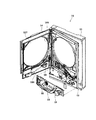
内枠12の構成を図3も用いて詳細に説明する。図3は、パチンコ機10から前面枠セット14を取り外した状態を示す正面図である(但し、図3では便宜上、遊技盤30面上の遊技領域内の構成を空白で示している)。   The configuration of the inner frame 12 will be described in detail with reference to FIG. FIG. 3 is a front view showing a state in which the front frame set 14 is removed from the pachinko machine 10 (however, in FIG. 3, the configuration in the game area on the surface of the game board 30 is shown as blank for convenience).

内枠12は、大別すると、その最下部に取り付けられた下皿ユニット13と、この下皿ユニット13よりも上側の範囲で内枠12の左側の上下方向の開閉軸線を軸心にして開閉自在に取り付けられた前面枠セット14と、後述する樹脂ベース20と、この樹脂ベース20の後側に取り付けられる遊技盤30とを備えている。これらの各構成を以下に詳細に説明する。   The inner frame 12 is roughly divided into a lower tray unit 13 attached to the lowermost portion thereof, and an opening / closing axis about the vertical opening / closing axis on the left side of the inner frame 12 in the range above the lower tray unit 13. A front frame set 14 that is freely attached, a resin base 20 that will be described later, and a game board 30 that is attached to the rear side of the resin base 20 are provided. Each of these configurations will be described in detail below.

下皿ユニット13は、内枠12に対してネジ等の締結具により固定されている。この下皿ユニット13の前面側には、下皿15と球抜きレバー17と遊技球発射ハンドル18と灰皿22と音出力口24が設けられている。球受皿としての下皿15は、下皿ユニット13のほぼ中央部に設けられており、排出口16より排出された遊技球が下皿15内に貯留可能になっている。球抜きレバー17は、下皿15内の遊技球を抜くためのものであり、この球抜きレバー17を図1で左側に移動させることにより、下皿15の底面の所定箇所が開口され、下皿15内に貯留された遊技球を下皿15の底面の開口部分を通して下方向外部に抜くことができる。遊技球発射ハンドル18は、下皿15よりも右方で手前側に突出して配設されている。遊技者による遊技球発射ハンドル18の操作に応じて、遊技球発射装置38によって遊技球が後述する遊技盤30の方へ打ち込まれるようになっている。遊技球発射装置38は、遊技球発射ハンドル18と後述するセットハンドル228と発射モータ229(図6参照)などで構成されている。なお、上述した遊技球発射装置38が本発明における遊技球発射手段に相当する。音出力口24は、下皿ユニット13内あるいは背面に設けられたスピーカからの音を出力するための出力口である。また、灰皿22は下皿15の左方に設けられている。灰皿22は左右方向(水平方向)の軸線を軸心にして回動(例えば前方側に向けて前回り)するように、その右側が下皿15に片持ち支持されている。   The lower plate unit 13 is fixed to the inner frame 12 with a fastener such as a screw. On the front side of the lower tray unit 13, a lower tray 15, a ball release lever 17, a game ball launching handle 18, an ashtray 22, and a sound output port 24 are provided. The lower tray 15 as a ball receiving tray is provided at the substantially central portion of the lower tray unit 13, and the game balls discharged from the discharge port 16 can be stored in the lower tray 15. The ball removal lever 17 is for removing a game ball in the lower plate 15. By moving the ball removal lever 17 to the left in FIG. 1, a predetermined position on the bottom surface of the lower plate 15 is opened, The game balls stored in the dish 15 can be pulled out downward through the opening on the bottom surface of the lower dish 15. The game ball launching handle 18 is disposed so as to protrude to the front side on the right side of the lower plate 15. In accordance with the operation of the game ball launching handle 18 by the player, the game ball launching device 38 drives the game ball toward a game board 30 described later. The game ball launching device 38 includes a game ball launching handle 18, a set handle 228, which will be described later, a launching motor 229 (see FIG. 6), and the like. The game ball launching device 38 described above corresponds to the game ball launching means in the present invention. The sound output port 24 is an output port for outputting sound from a speaker provided in the lower plate unit 13 or on the back surface. The ashtray 22 is provided on the left side of the lower plate 15. The right side of the ashtray 22 is cantilevered by the lower plate 15 so that the ashtray 22 rotates about the axis in the left-right direction (horizontal direction).

なお、下皿ユニット13はその大部分が内枠12と同様、ABS樹脂にて成形されている。こうすることで、粘性が高く衝撃に強くでき、低コストで製造できる。特に、下皿15を形成する表面層と下皿奥方の前面パネル部分とを難燃性のABS樹脂にて成形している。このため、この部分は燃え難くなっている。   Note that most of the lower dish unit 13 is molded of ABS resin in the same manner as the inner frame 12. By doing so, it is highly viscous and resistant to impact, and can be manufactured at low cost. In particular, the surface layer forming the lower plate 15 and the front panel portion behind the lower plate are formed of flame-retardant ABS resin. For this reason, this part is difficult to burn.

また、前面枠セット14は、図2に示すように、内枠12に対して開閉可能に取り付けられており、内枠12と同様、パチンコ機10の正面からみて左側に上下に延びる開閉軸線を軸心にして前方側に開放できるようになっている。しかも前面枠セット14は内枠12の外側壁(リブ)12b(図3参照)内に嵌まり込むようにして取り付けられている。つまり、この前面枠セット14の側面の少なくとも一部が内枠12の外側壁(リブ)12b内に嵌まり込むようにして取り付けられているので、内枠12と前面枠セット14との隙間から異物(針状あるいは薄板状等のもの)を差し入れるなどの不正行為を防止できるようになっている。また、前面枠セット14は、内枠12と同様に、合成樹脂、具体的にはABS樹脂により構成されているので、粘性が高く衝撃に強くでき、低コストで製造できる。   As shown in FIG. 2, the front frame set 14 is attached to the inner frame 12 so as to be openable and closable. Like the inner frame 12, the front frame set 14 has an open / close axis extending vertically to the left when viewed from the front of the pachinko machine 10. It can be opened to the front side with an axial center. Moreover, the front frame set 14 is attached so as to fit into the outer wall (rib) 12b (see FIG. 3) of the inner frame 12. That is, since at least a part of the side surface of the front frame set 14 is attached so as to fit into the outer wall (rib) 12b of the inner frame 12, foreign matter (from the gap between the inner frame 12 and the front frame set 14) Such as a needle or thin plate) can be prevented. Further, since the front frame set 14 is made of a synthetic resin, specifically, an ABS resin, like the inner frame 12, the front frame set 14 is highly viscous and strong against impact, and can be manufactured at low cost.

一方、前面枠セット14の下部(上述の下皿15の上方位置)には、遊技球の受皿としての上皿19が一体的に設けられている。ここで、上皿19は、遊技球を一旦貯留し、一列に整列させながら遊技球発射装置38の方へ導出するための球受皿である。従来のパチンコ機では前面枠セットの下方に内枠に対し開閉可能な前飾り枠が設けられ、該前飾り枠に上皿が設けられていたのであるが、本実施の形態では前飾り枠が省略され、前面枠セット14に対し直接的に上皿19が設けられている。この上皿19も下皿15と同様、表面層が難燃性のABS樹脂にて成形される構成となっている。   On the other hand, an upper plate 19 as a receiving tray for game balls is integrally provided below the front frame set 14 (above the lower plate 15). Here, the upper tray 19 is a ball tray for temporarily storing the game balls and guiding them to the game ball launching device 38 while aligning them in a line. In the conventional pachinko machine, a front decorative frame that can be opened and closed with respect to the inner frame is provided below the front frame set, and the upper decorative frame is provided on the front decorative frame. The upper plate 19 is provided directly to the front frame set 14 and is omitted. Similar to the lower plate 15, the upper plate 19 has a structure in which the surface layer is formed of flame-retardant ABS resin.

ここで、前面枠セット14は、少なくとも遊技球発射ハンドル18に干渉しないようにして本パチンコ機10の下方に拡張して設けられており、具体的な数値を示すと、パチンコ機10の下端から前面枠セット14の下端までの寸法(図1のH1)は、既存の一機種で例えば約201mmであるのに対し、本パチンコ機10では30mm程小さく、約172mmとなっている。また、これに伴いパチンコ機10の下端から上皿19までの寸法(図1のH2)も小さくなっており、既存の一機種では例えば約298mmであるのに対し、本パチンコ機10では261mmとなっている。かかる構成では、上皿19の位置を下げたことにより、球貸し装置のノズル部と上皿19との距離が大きくなって貸し出される遊技球のこぼれ落ちなどが懸念されるが、本実施例では、当該ノズル部からの遊技球を受ける部分(向かって左側部分)で上皿19の周囲壁の一部を高くした(図1の高壁部19a)。これにより、上皿19の位置を下げた構成にあっても貸し遊技球のこぼれ落ち等の不都合が解消されるようになっている。なお、高壁部19aの高さ寸法は、上皿19の下げ寸法に見合うものであればよく、本実施例では25mmとした。   Here, the front frame set 14 is provided below the pachinko machine 10 so as not to interfere with at least the game ball launching handle 18. The dimension (H1 in FIG. 1) to the lower end of the front frame set 14 is, for example, about 201 mm in one existing model, but is about 172 mm, which is about 30 mm smaller in the pachinko machine 10. In addition, along with this, the dimension from the lower end of the pachinko machine 10 to the upper plate 19 (H2 in FIG. 1) is also reduced. It has become. In such a configuration, there is a concern that the distance between the nozzle portion of the ball lending device and the upper plate 19 will increase due to the lowering of the position of the upper plate 19, and the spilled gaming balls will be rented. A part of the peripheral wall of the upper plate 19 was raised at a portion (left side portion) that receives the game ball from the nozzle portion (the high wall portion 19a in FIG. 1). Thereby, even if it is the structure which lowered the position of the upper plate 19, inconveniences, such as spilling out of a rental game ball, are eliminated. In addition, the height dimension of the high wall part 19a should just be commensurate with the down dimension of the upper plate 19, and was 25 mm in the present Example.

図3に示すように、内枠12は、外形が矩形状の樹脂ベース20を主体に構成されており、樹脂ベース20の中央部には略円形状の窓孔21が形成されている。樹脂ベース20の後側には遊技盤30が着脱可能に装着されている。遊技盤30は四角形状の合板よりなり、その周縁部が樹脂ベース20(内枠12)の裏側に当接した状態で取着されている。従って、遊技盤30の前面部の略中央部分が樹脂ベース20の窓孔21を通じて内枠12の前面側に露出した状態となっている。なお、遊技盤30の上下方向の長さは476mm、左右方向の長さは452mmとなっている(従来と同等サイズ)。   As shown in FIG. 3, the inner frame 12 is mainly composed of a resin base 20 having a rectangular outer shape, and a substantially circular window hole 21 is formed at the center of the resin base 20. A game board 30 is detachably mounted on the rear side of the resin base 20. The game board 30 is made of a rectangular plywood and is attached in a state in which the peripheral edge thereof is in contact with the back side of the resin base 20 (inner frame 12). Accordingly, the substantially central portion of the front surface portion of the game board 30 is exposed to the front surface side of the inner frame 12 through the window hole 21 of the resin base 20. The game board 30 has a vertical length of 476 mm and a horizontal length of 452 mm (same size as before).

次に、図4を用いて遊技盤30の構成を説明する。図4は遊技盤30の構成を示す正面図である。遊技盤30は、一般入賞口31、可変入賞装置32、第1の始動口33(例えば作動チャッカ)、第2の始動口34(例えばスルーゲート)、可変表示装置ユニット35等を備えている。これらの一般入賞口31、可変入賞装置32、第1の始動口33(例えば作動チャッカ)、第2の始動口34(例えばスルーゲート)、可変表示装置ユニット35等は、遊技盤30における、ルータ加工によって形成された各貫通穴にそれぞれに配設され、遊技盤30前面側から木ネジ等により取り付けられている。前述の一般入賞口31、可変入賞装置32および第1の始動口33に遊技球が入球し、当該入球が後述する検出スイッチ(入賞口スイッチ221、カウントスイッチ223、作動口スイッチ224等)で検出され、この検出スイッチの出力に基づいて、上皿19(または下皿15)へ所定数の賞品球が払い出される。その他に、遊技盤30にはアウト口36が設けられており、各種入賞装置等に入球しなかった遊技球はこのアウト口36を通って図示しない球排出路の方へと案内されるようになっている。遊技盤30には、遊技球の落下方向を適宜分散、調整等するために多数の釘が植設されているとともに、風車37等の各種部材(役物)が配設されている。   Next, the configuration of the game board 30 will be described with reference to FIG. FIG. 4 is a front view showing the configuration of the game board 30. The game board 30 includes a general winning port 31, a variable winning device 32, a first starting port 33 (for example, an operation chucker), a second starting port 34 (for example, a through gate), a variable display unit 35, and the like. These general winning port 31, variable winning device 32, first starting port 33 (for example, operation chucker), second starting port 34 (for example, through gate), variable display unit 35, etc. It is arranged in each through hole formed by machining, and is attached from the front side of the game board 30 with wood screws or the like. A game ball enters the above-described general winning port 31, variable winning device 32, and first starting port 33, and the detected balls are described later (a winning port switch 221, a count switch 223, an operating port switch 224, etc.). Based on the output of the detection switch, a predetermined number of prize balls are paid out to the upper plate 19 (or the lower plate 15). In addition, the game board 30 is provided with an out port 36, and game balls that have not entered the various winning devices etc. are guided through the out port 36 to a ball discharge path (not shown). It has become. A number of nails are planted in the game board 30 in order to appropriately disperse and adjust the falling direction of the game balls, and various members (acts) such as the windmill 37 are arranged.

可変表示装置ユニット35は、第1の始動口33への入賞をトリガとして、識別情報としての第1図柄(例えば特別図柄)を変動表示する第1図柄表示装置42と、第2の始動口34の通過をトリガとして、第2図柄(例えば普通図柄)を変動表示する第2図柄表示装置41とを備えている。   The variable display unit 35 has a first symbol display device 42 for variably displaying a first symbol (for example, a special symbol) as identification information with a winning at the first starting port 33 as a trigger, and a second starting port 34. And a second symbol display device 41 for variably displaying a second symbol (for example, a normal symbol).

第2図柄表示装置41は、第2図柄用の表示部43と保留ランプ44とを有し、遊技球が第2の始動口34を通過する毎に例えば表示部43による表示図柄(普通図柄)が変動し、その変動表示が所定図柄で停止した場合に第1の始動口33が所定時間だけ作動状態となる(開放される)よう構成されている。遊技球が第2の始動口34を通過した回数は最大4回まで保留され、その保留回数が保留ランプ44にて点灯表示されるようになっている。なお、表示部43は、複数のランプの点灯を切り換えることにより変動表示される構成の他、第1図柄表示装置42(液晶表示装置)の一部で変動表示される構成等であっても良い。保留ランプ44も同様に、第1図柄表示装置42の一部で変動表示される構成等であっても良い。なお、上述した第2図柄表示装置41が本発明における普通識別情報変動表示手段に相当する。   The second symbol display device 41 includes a second symbol display unit 43 and a holding lamp 44, and each time a game ball passes through the second starting port 34, for example, a display symbol (ordinary symbol) by the display unit 43 is displayed. Is changed, and when the change display stops at a predetermined symbol, the first start port 33 is configured to be in an activated state (opened) for a predetermined time. The number of times that the game ball has passed through the second start opening 34 is held up to a maximum of 4 times, and the number of times the game ball is held is lit and displayed by the hold lamp 44. The display unit 43 may be configured to be variably displayed by a part of the first symbol display device 42 (liquid crystal display device) in addition to the configuration to be variably displayed by switching lighting of a plurality of lamps. . Similarly, the hold lamp 44 may be configured to be variably displayed on a part of the first symbol display device 42. The second symbol display device 41 described above corresponds to the normal identification information variation display means in the present invention.

第1図柄表示装置42は液晶表示装置として構成されており、後述する表示制御装置45により表示内容が制御される。第1図柄表示装置42には、例えば左、中及び右の3つの図柄列が表示される。各図柄列は複数の図柄によって構成されており、これら図柄が図柄列毎にスクロールされるようにして第1図柄表示装置42に可変表示されるようになっている。なお本実施の形態では、第1図柄表示装置42(液晶表示装置)は8インチサイズの大型の液晶ディスプレイを備える。可変表示装置ユニット35には、第1図柄表示装置42を囲むようにしてセンターフレーム47が配設されている。なお、上述した第1図柄表示装置42が本発明における識別情報変動表示手段に相当し、上述した表示制御装置45が本発明における表示制御手段に相当する。   The first symbol display device 42 is configured as a liquid crystal display device, and the display content is controlled by a display control device 45 described later. The first symbol display device 42 displays, for example, three symbol rows of left, middle and right. Each symbol row is composed of a plurality of symbols, and these symbols are variably displayed on the first symbol display device 42 so as to be scrolled for each symbol row. In the present embodiment, the first symbol display device 42 (liquid crystal display device) includes a large liquid crystal display of 8 inches. The variable display device unit 35 is provided with a center frame 47 so as to surround the first symbol display device 42. The first symbol display device 42 described above corresponds to the identification information fluctuation display means in the present invention, and the display control device 45 described above corresponds to the display control means in the present invention.

可変入賞装置32は、通常は遊技球が入賞できない又は入賞し難い閉状態になっており、大当たりの際に遊技球が入賞しやすい開状態と通常の閉状態とに繰り返し作動されるようになっている。より詳しくは、第1の始動口33に対し遊技球が入賞すると第1図柄表示装置42で図柄が変動表示され、その停止後の確定図柄が予め設定した特定の図柄の組合せとなったことを必要条件に特別遊技状態が発生する。そして、可変入賞装置32の大入賞口が所定の開放状態となり、遊技球が入賞しやすい状態(大当たり状態)になるよう構成されている。具体的には、所定時間の経過又は所定個数の入賞を1ラウンドとして、可変入賞装置32の大入賞口が所定回数繰り返し開放される。遊技球が第1の始動口33を通過した回数は最大4回まで保留され、その保留回数が保留ランプ46にて点灯表示されるようになっている。なお、保留ランプ46は、第1図柄表示装置42の一部で変動表示される構成等であっても良い。   The variable winning device 32 is normally in a closed state in which a game ball cannot be won or difficult to win, and is repeatedly operated between an open state in which a game ball is easy to win and a normal closed state in the event of a big win. ing. More specifically, when a game ball wins at the first start opening 33, the symbols are displayed in a variable manner on the first symbol display device 42, and the confirmed symbol after the stop is a combination of specific symbols set in advance. A special gaming state occurs as a necessary condition. The large winning opening of the variable winning device 32 is in a predetermined open state, and the game ball is configured to be in a state where it is easy to win a prize (a big hit state). Specifically, the passage of a predetermined time or a predetermined number of winnings is defined as one round, and the big winning opening of the variable winning device 32 is repeatedly opened a predetermined number of times. The number of times that the game ball has passed through the first start port 33 is held up to a maximum of 4 times, and the number of times that the game ball is held is lit on the hold lamp 46. Note that the hold lamp 46 may be configured so as to be variably displayed on a part of the first symbol display device 42.

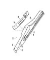
また、遊技盤30には、遊技球発射装置38から発射された遊技球を遊技盤30上部へ案内するためのレールユニット50が取り付けられており、遊技球発射ハンドル18の回動操作に伴い発射された遊技球はレールユニット50を通じて所定の遊技領域に案内されるようになっている。レールユニット50はリング状をなす樹脂成型品(例えば、フッ素樹脂が添加されて成形されたもの)にて構成されており、内外二重に一体形成された内レール51と外レール52とを有する。なお、レールユニット50はフッ素樹脂を添加して成形されているので、図3に示す奥面50aについての遊技球の摩擦抵抗を少なくできる。内レール51は上方の約1/4ほどを除いて略円環状に形成され、一部(主に左側部)が内レール51に向かい合うようにして外レール52が形成されている。かかる場合、内レール51と外レール52とにより誘導レールが構成され、これら各レール51,52が所定間隔を隔てて並行する部分(向かって左側の部分)により球案内通路が形成されている。なお、球案内通路は、遊技盤30との当接面を有した溝状、すなわち手前側を開放した溝状に形成されている。   The game board 30 is also provided with a rail unit 50 for guiding the game ball launched from the game ball launching device 38 to the upper part of the game board 30, and is released in accordance with the turning operation of the game ball launch handle 18. The played game balls are guided to a predetermined game area through the rail unit 50. The rail unit 50 is formed of a ring-shaped resin molded product (for example, a product molded by adding a fluororesin), and has an inner rail 51 and an outer rail 52 integrally formed in an inner and outer double. . In addition, since the rail unit 50 is shape | molded by adding a fluororesin, it can reduce the frictional resistance of the game ball about the back surface 50a shown in FIG. The inner rail 51 is formed in a substantially annular shape except for about ¼ of the upper part, and the outer rail 52 is formed so that a part (mainly the left side) faces the inner rail 51. In such a case, a guide rail is constituted by the inner rail 51 and the outer rail 52, and a spherical guide passage is formed by a portion (the left portion facing) where the rails 51 and 52 are parallel to each other at a predetermined interval. The ball guide passage is formed in a groove shape having a contact surface with the game board 30, that is, a groove shape in which the front side is opened.

内レール51の先端部分(図4の左上部)には戻り球防止部材53が取着されている。これにより、一旦、内レール51及び外レール52間の球案内通路から遊技盤30の上部へと案内された遊技球が再度球案内通路内に戻ってしまうといった事態が防止されるようになっている。また、外レール52には、遊技球の最大飛翔部分に対応する位置(図4の右上部:外レール52の先端部に相当する部位)に返しゴム54が取着されている。従って、所定以上の勢いで発射された遊技球は、返しゴム54に当たって跳ね返されるようになっている。外レール52の内側面には、遊技球の飛翔をより滑らかなものとするべく、つまり遊技球の摩擦抵抗を少なくするべく、長尺状をなすステンレス製の金属帯としての摺動プレート55が取着されている。   A return ball preventing member 53 is attached to the tip portion of the inner rail 51 (the upper left portion in FIG. 4). This prevents a situation in which the game ball once guided from the ball guide path between the inner rail 51 and the outer rail 52 to the upper part of the game board 30 returns to the ball guide path again. Yes. Further, a return rubber 54 is attached to the outer rail 52 at a position corresponding to the maximum flight portion of the game ball (upper right portion in FIG. 4: a portion corresponding to the tip portion of the outer rail 52). Accordingly, the game ball fired at a predetermined momentum or more hits the return rubber 54 and is bounced back. On the inner surface of the outer rail 52, there is a sliding plate 55 as a long metal strip made of stainless steel in order to make the flight of the game ball smoother, that is, to reduce the frictional resistance of the game ball. It is attached.

また、レールユニット50の外周部には、外方へ張り出した円弧状のフランジ56が形成されている。フランジ56は、遊技盤30に対する取付面を構成する。レールユニット50が遊技盤30に取り付けられる際には、遊技盤30上にフランジ56が当接され、その状態で、当該フランジ56に形成された複数の透孔にネジ等が挿通されて遊技盤30に対するレールユニット50の締結がなされるようになっている。この実施例では、レールユニット50の少なくとも左側を遊技盤30に強固に締結するために、レールユニット50の左側はその右側よりも多いネジで遊技盤30に締結されているので、レールユニット50の左側についての遊技盤30への密着性を上げることができ、遊技球の球飛びを良くすることができる。レールユニット50の左側が遊技盤30に対してぐらついているとこのレールユニット50に出射された遊技球の勢いが当該ぐらつきにより吸収されてしまうからである。   An arc-shaped flange 56 projecting outward is formed on the outer peripheral portion of the rail unit 50. The flange 56 constitutes a mounting surface for the game board 30. When the rail unit 50 is attached to the game board 30, the flange 56 is brought into contact with the game board 30, and in this state, screws or the like are inserted into the plurality of through holes formed in the flange 56 and the game board 30. The rail unit 50 is fastened to 30. In this embodiment, in order to firmly fasten at least the left side of the rail unit 50 to the game board 30, the left side of the rail unit 50 is fastened to the game board 30 with more screws than the right side. Adhesiveness to the game board 30 on the left side can be improved, and a game ball can be improved. This is because if the left side of the rail unit 50 is wobbled with respect to the game board 30, the momentum of the game ball emitted to the rail unit 50 is absorbed by the wobble.

さらに本実施の形態では、正面から見てレールユニット50の上下左右の各端部は略直線状に(平坦に)形成されている。つまり、レールユニット50の上下左右の各端部においてはフランジ56が切り落とされ、パチンコ機10における有限の領域にてレール径の拡張、すなわち遊技盤30上の遊技領域の拡張が図られるようになっている。   Furthermore, in the present embodiment, the top, bottom, left, and right ends of the rail unit 50 are formed substantially linearly (flatly) as viewed from the front. That is, the flange 56 is cut off at each of the upper, lower, left, and right ends of the rail unit 50, so that the rail diameter can be expanded in a limited area in the pachinko machine 10, that is, the game area on the game board 30 can be expanded. ing.

内レール51及び外レール52間の球案内通路の入口には、同球案内通路の一部を閉鎖するようにして凸部57が形成されている。この凸部57は、内レール51からレールユニット50下端部にかけて略鉛直方向に設けられ、遊技領域まで至らず球案内通路内を逆流してくるファール球をファール球通路63(図3参照)に導くための役目をなす。なお、遊技盤30の右下隅部及び左下隅部は、証紙(例えば製造番号が記載されている)等のシール(図4のS1,S2)やプレートを貼着するためのスペースとなっており、この貼着スペースを確保するために、フランジ56に切欠58,59が形成されている。遊技盤30の右下隅部や左下隅部に、証紙等のシール(図4のS1,S2)を貼着することで、遊技盤30と証紙との一義性を持たせることができる。   A convex portion 57 is formed at the entrance of the ball guide passage between the inner rail 51 and the outer rail 52 so as to close a part of the ball guide passage. The convex portion 57 is provided in a substantially vertical direction from the inner rail 51 to the lower end portion of the rail unit 50, and a foul ball that does not reach the game area and flows backward in the ball guide passage is used as a foul ball passage 63 (see FIG. 3). Play a role in guiding. The lower right corner and the lower left corner of the game board 30 are spaces for sticking stickers (S1, S2 in FIG. 4) and plates such as stamps (for example, serial numbers are described). In order to secure this adhering space, notches 58 and 59 are formed in the flange 56. By sticking a seal such as a certificate (S1, S2 in FIG. 4) to the lower right corner or the lower left corner of the game board 30, the game board 30 and the certificate can be uniquely defined.

次に、遊技領域について説明する。遊技領域は、レールユニット50の内周部(内外レール)により略円形状に区画形成されており、特に本実施の形態では、遊技盤30の盤面上に区画される遊技領域が従来よりもはるかに大きく構成されている。本実施の形態では、外レール52の最上部地点から遊技盤30下部までの間の距離は445mm(従来品よりも58mm長い)、外レール52の極左位置から内レール51の極右位置までの間の距離は435mm(従来品よりも50mm長い)となっている。また、内レール51の極左位置から内レール51の極右位置までの間の距離は418mmとなっている。   Next, the game area will be described. The game area is partitioned and formed in a substantially circular shape by the inner peripheral part (inner and outer rails) of the rail unit 50. In particular, in the present embodiment, the game area partitioned on the board surface of the game board 30 is much more than conventional. It is composed largely. In the present embodiment, the distance between the uppermost point of the outer rail 52 and the lower part of the game board 30 is 445 mm (58 mm longer than the conventional product), and is from the extreme left position of the outer rail 52 to the extreme right position of the inner rail 51. The distance is 435 mm (50 mm longer than the conventional product). The distance from the extreme left position of the inner rail 51 to the extreme right position of the inner rail 51 is 418 mm.

本実施の形態では、遊技領域を、パチンコ機10の正面から見て、内レール51及び外レール52によって囲まれる領域のうち、内外レール51,52の並行部分である誘導レールの領域を除いた領域としている。従って、遊技領域と言った場合には誘導レール部分は含まないため、遊技領域の向かって左側限界位置は外レール52によってではなく内レール51によって特定される。同様に、遊技領域の向かって右側限界位置は内レール51によって特定される。また、遊技領域の下側限界位置は遊技盤30の下端位置によって特定される。また、遊技領域の上側限界位置は外レール52によって特定される。   In the present embodiment, the game area is a region surrounded by the inner rail 51 and the outer rail 52 as viewed from the front of the pachinko machine 10, except for a guide rail region that is a parallel part of the inner and outer rails 51 and 52. As an area. Accordingly, since the game area does not include the guide rail portion, the left limit position toward the game area is specified not by the outer rail 52 but by the inner rail 51. Similarly, the right limit position toward the game area is specified by the inner rail 51. The lower limit position of the game area is specified by the lower end position of the game board 30. The upper limit position of the game area is specified by the outer rail 52.

従って、本実施の形態では、遊技領域の幅(左右方向の最大幅)は、418mmであり、遊技領域の高さ(上下方向の最大幅)は、445mmである。   Therefore, in the present embodiment, the width of the gaming area (maximum width in the left-right direction) is 418 mm, and the height of the gaming area (maximum width in the vertical direction) is 445 mm.

ここで、前記遊技領域の幅は、少なくとも380mm以上あることが望ましい。より好ましくは390mm以上、400mm以上、410mm以上、420mm以上、430mm以上、440mm以上、450mm以上、さらに460mm以上であることが望ましい。もちろん、470mm以上であってもよい。すなわち、遊技領域の幅は、遊技領域拡大という観点からは大きい程好ましい。また、遊技領域の高さは、少なくとも400mm以上あることが望ましい。より好ましくは410mm以上、420mm以上、430mm以上、440mm以上、450mm以上、さらには460mm以上であることがより望ましい。もちろん、470mm以上、480mm以上、490mm以上としてもよい。すなわち、遊技領域の高さは、遊技領域拡大という観点からは大きい程好ましい。なお、上記幅及び高さの組合せについては、上記数値を任意に組み合わせたものとしてもよい。   Here, the width of the gaming area is preferably at least 380 mm. More preferably, it is 390 mm or more, 400 mm or more, 410 mm or more, 420 mm or more, 430 mm or more, 440 mm or more, 450 mm or more, and further 460 mm or more. Of course, it may be 470 mm or more. That is, the width of the game area is preferably as large as possible from the viewpoint of expanding the game area. The height of the game area is preferably at least 400 mm. More preferably, it is 410 mm or more, 420 mm or more, 430 mm or more, 440 mm or more, 450 mm or more, and more preferably 460 mm or more. Of course, it is good also as 470 mm or more, 480 mm or more, and 490 mm or more. That is, the height of the game area is preferably as large as possible from the viewpoint of game area expansion. In addition, about the combination of the said width | variety and height, it is good also as what combined the said numerical value arbitrarily.

本実施の形態では、遊技盤30面に対する遊技領域の面積の比率は約70%と、従来に比べ格段に面積比が大きいものとなっている。なお、遊技盤30面に対する遊技領域の面積比は、従来では50%程度に過ぎなかったことから、遊技盤30を共通とした前提においてはかなり遊技領域を拡大しているといえる。尚、パチンコ機10の外形は遊技場への設置の都合上製造者間でほぼ統一されており、遊技盤30の大きさも同様とせざるを得ない状況下において、上記のように遊技盤30面に対する遊技領域の面積の比率を約20%も高めたことは、遊技領域拡大の観点で非常に有意義である。ここで、前記比率は、少なくとも60%以上であることが望ましい。さらに好ましくは65%以上であり、より好ましくは70%以上である。また、本実施形態の場合を越えて75%以上であれば、一層望ましい。さらには、80%以上であってもよい。   In the present embodiment, the ratio of the area of the game area to the surface of the game board 30 is about 70%, which is a much larger area ratio than before. Note that the area ratio of the game area to the surface of the game board 30 is only about 50% in the past, so it can be said that the game area is considerably expanded on the premise that the game board 30 is shared. It should be noted that the external shape of the pachinko machine 10 is almost uniform among manufacturers for the convenience of installation in the game hall, and in the situation where the size of the game board 30 must be the same, the surface of the game board 30 as described above. Increasing the ratio of the area of the gaming area to about 20% is very significant from the viewpoint of expanding the gaming area. Here, the ratio is preferably at least 60% or more. More preferably, it is 65% or more, More preferably, it is 70% or more. Further, if it is 75% or more exceeding the case of this embodiment, it is more desirable. Furthermore, it may be 80% or more.

また、パチンコ機10全体の正面側の面積に対する遊技領域の面積の比率は約40%と、従来に比べ格段に面積比が大きいものとなっている。なお、パチンコ機10全体の正面側の面積に対する遊技領域の面積比は、35パーセント以上であるのが望ましい。もちろん、40パーセント以上としてもよいし、45パーセント以上、又は50パーセント以上としてもよい。   Moreover, the ratio of the area of the game area to the area of the front side of the entire pachinko machine 10 is about 40%, which is a much larger area ratio than before. The area ratio of the game area to the area on the front side of the entire pachinko machine 10 is desirably 35% or more. Of course, it may be 40% or more, 45% or more, or 50% or more.

なお、可変表示装置ユニット35の両側に位置する第2の始動口34は、該第2の始動口34を通過した遊技球が中央の方へ寄せられるような案内機構を有している。これにより、遊技領域が左右方向に拡張されている場合であっても、遊技球を中央の第1の始動口33や可変入賞装置32の方へと案内することができ、ひいては、遊技領域が拡張されることにより遊技球が入賞しにくくなることによる興趣の低下が抑制されるようになっている。さらには、遊技領域が左右方向に拡張されていることによって、風車37、第2の始動口34、複数の釘(遊技球を中央に誘導するための誘導釘)、他の役物を種々配設することができ、可変表示装置ユニット35の左右両側の遊技領域での遊技球の挙動を一層面白くすることができるようになっている。また、遊技領域が上下方向にも拡張されていることから、さらに風車37、第2の始動口34、複数の釘、他の役物を種々配設することができ、遊技領域での上下方向の遊技球の挙動をより一層面白くすることができるようになっている。   In addition, the 2nd starting port 34 located in the both sides of the variable display apparatus unit 35 has a guide mechanism in which the game ball which passed this 2nd starting port 34 is approached toward the center. Thereby, even when the game area is expanded in the left-right direction, the game ball can be guided toward the center first starting port 33 and the variable prize-winning device 32. By expanding, it is possible to suppress a decrease in interest due to difficulty in winning a game ball. Furthermore, by extending the game area in the left-right direction, various arrangements of the windmill 37, the second start port 34, a plurality of nails (guide nails for guiding the game ball to the center), and other accessories are arranged. Thus, the behavior of the game ball in the game areas on the left and right sides of the variable display device unit 35 can be made more interesting. In addition, since the game area is also expanded in the vertical direction, various windmills 37, second start ports 34, a plurality of nails, and other accessories can be further arranged in the vertical direction in the game area. The behavior of the game ball can be made even more interesting.

図3の説明に戻り、前記樹脂ベース20において、窓孔21(遊技盤30)の下方には、遊技球発射装置38より発射された直後に遊技球を案内するための発射レール61が取り付けられている。発射レール61は、その後方の金属板62を介して樹脂ベース20に取付固定されており、所定の発射角度(打ち出し角度)にて直線的に延びるよう構成されている。従って、遊技球発射ハンドル18の回動操作に伴い発射された遊技球は、まずは発射レール61に沿って斜め上方に打ち出され、その後前述した通りレールユニット50の球案内通路を通じて所定の遊技領域に案内されるようになっている。   Returning to the description of FIG. 3, in the resin base 20, below the window hole 21 (game board 30), a launch rail 61 for guiding the game ball immediately after being launched from the game ball launcher 38 is attached. ing. The firing rail 61 is fixedly attached to the resin base 20 via a metal plate 62 behind the firing rail 61, and is configured to extend linearly at a predetermined firing angle (launch angle). Therefore, the game ball launched by the turning operation of the game ball launching handle 18 is first launched obliquely upward along the launch rail 61, and then into a predetermined game area through the ball guide path of the rail unit 50 as described above. Guided.

本パチンコ機10の場合、遊技領域が従来よりも大幅に拡張されることは既に述べたが、かかる構成下では、誘導レールの曲率を小さくせざるを得ないことから、打出球を安定化させるための工夫を要する。そこで本実施の形態では、遊技球の発射位置を低くするとともに発射レール61の傾斜角度(発射角度)を既存のものよりも幾分大きくし(すなわち発射レール61を立ち上げるようにし)、さらに発射レール61の長さを既存のものよりも長くして十分な長さの球誘導距離を確保するようにしている。これにより、遊技球発射装置38から発射された遊技球をより安定した状態で誘導レールに案内できるようにしている。この場合特に、発射レール61を、遊技球発射装置38の発射位置から遊技領域の中央位置(アウト口36)を越える位置まで延びるよう形成している。   In the case of this pachinko machine 10, it has already been described that the game area is greatly expanded compared to the conventional case, but under such a configuration, the curvature of the guide rail must be reduced, so that the launch ball is stabilized. Need some ingenuity. Therefore, in the present embodiment, the launch position of the game ball is lowered and the inclination angle (launch angle) of the launch rail 61 is made somewhat larger than that of the existing one (that is, the launch rail 61 is raised) to further launch. The length of the rail 61 is made longer than the existing one so as to ensure a sufficiently long ball guiding distance. Thereby, the game ball launched from the game ball launcher 38 can be guided to the guide rail in a more stable state. In this case, in particular, the launch rail 61 is formed to extend from the launch position of the game ball launcher 38 to a position beyond the center position (out port 36) of the game area.

また、発射レール61とレールユニット50(誘導レール)との間には所定間隔の隙間があり、この隙間より下方にファール球通路63が形成されている。従って、仮に、遊技球発射装置38から発射された遊技球が戻り球防止部材53まで至らずファール球として誘導レール内を逆戻りする場合には、そのファール球がファール球通路63を介して下皿15に排出される。因みに、本実施の形態の場合、発射レール61の長さは約240mm、発射レール先端部の隙間の長さ(発射レール61の延長線上の長さ)は約40mmである。   In addition, there is a predetermined gap between the firing rail 61 and the rail unit 50 (guide rail), and a foul ball passage 63 is formed below the gap. Therefore, if the game ball launched from the game ball launching device 38 does not reach the return ball prevention member 53 and returns to the inside of the guide rail as a foul ball, the foul ball passes through the foul ball passage 63 to the lower plate. 15 is discharged. Incidentally, in the case of the present embodiment, the length of the firing rail 61 is about 240 mm, and the length of the gap at the tip of the firing rail (the length on the extension line of the firing rail 61) is about 40 mm.

ファール球が誘導レール内を逆流してくる際、その多くは外レール52に沿って流れ、外レール52の下端部に到達した時点で下方に落下するが、一部のファール球は誘導レール内で暴れ、内レール51側へ跳ね上がるものもある。この際、跳ね上がったファール球は、球案内通路入口の前記凸部57に当たり、ファール球通路63に誘導される。これにより、ファール球の全てがファール球通路63に確実に案内されるようになる。これにより、ファール球と次に発射される遊技球との干渉が抑制される。   When the foul spheres flow backward in the guide rail, most of them flow along the outer rail 52 and drop downward when reaching the lower end of the outer rail 52. There is also a thing that jumps to the inner rail 51 side. At this time, the splashed foul ball hits the convex portion 57 at the entrance of the ball guide passage and is guided to the foul ball passage 63. Thereby, all of the foul balls are surely guided to the foul ball passage 63. This suppresses interference between the foul ball and the next game ball to be launched.

なお、詳しい図面の開示は省略するが、遊技球発射装置38には、前面枠セット14側の球出口(上皿19の最下流部より通じる球出口)から遊技球が1つずつ供給される。この際、本実施の形態では遊技球の発射位置を低くしたため、前面枠セット14側の球出口から前記発射位置への落差が大きくなるが、発射レール61の基端部付近にはその右側と手前側にそれぞれガイド部材65,66を設置した。これにより、前面枠セット14側の球出口から供給される遊技球が常に所定の発射位置にセットされ、安定した発射動作が実現できる。また、遊技球発射装置38には打球槌が設けられ、軸部を中心とする打球槌の回動に伴い遊技球が発射されるが、打球槌に関して軽量化が望まれている。それ故、アルミニウム等の軽金属への材料変更や軸部寸法の縮小化により打球槌の軽量化を図る一方で、十分な発射力を確保すべく、打球槌のヘッド部(軸部と反対側の端部)に重り部を設けている。これにより、十分でかつ安定した遊技球の発射が実現できる。打球槌の重り部を上方に突出して設けることにより、打球槌を容易に摘んだりひっかけたりすることができ、槌先の打球強さの調整等がし易くなるという効果がある。   Although detailed disclosure of the drawings is omitted, game balls are supplied to the game ball launcher 38 one by one from the ball outlet on the front frame set 14 side (the ball outlet leading from the most downstream portion of the upper plate 19). . At this time, since the launch position of the game ball is lowered in the present embodiment, the drop from the exit of the ball on the front frame set 14 side to the launch position becomes large. Guide members 65 and 66 were installed on the front side. Thereby, the game ball supplied from the ball exit on the front frame set 14 side is always set at a predetermined launch position, and a stable launch operation can be realized. Further, the game ball launching device 38 is provided with a ball striking ball, and a game ball is launched with the rotation of the ball striking center around the shaft portion. Therefore, while aiming to reduce the weight of the hitting ball by changing the material to light metal such as aluminum and reducing the size of the shaft, the head of the hitting ball (on the opposite side of the shaft) is secured to ensure sufficient firing force. A weight is provided at the end. Thereby, sufficient and stable launch of the game ball can be realized. By providing the weight portion of the hitting ball projecting upward, the hitting ball can be easily picked up or caught, and it is easy to adjust the hitting ball strength of the tip.

なお、図3中の符号67は上皿19に通ずる排出口であり、この排出口67を介して遊技球が上皿19に排出される。排出口67には、略水平方向の回転軸を軸心として略水平状態と略垂直状態とに変位する開閉式のシャッタ68が取り付けられている。前面枠セット14を内枠12から開放した状態(図3の状態)では、バネ等の付勢力によりシャッタ68が略水平状態から略垂直状態となり、排出口67から遊技球がこぼれ落ちないようにこの排出口67を閉鎖する。また、前面枠セット14を閉鎖した状態では、当該前面枠セット14の裏面に設けられた球通路樋69(図2参照)によりシャッタ68が押し開けられて略水平状態になり、排出口67の方へ排出された遊技球はもれなく球通路樋69を通って上皿19に排出されるようになる。従って、前飾り枠が省略され前面枠セット14に対して上皿19が直接設けられる構成とした本パチンコ機10において、前面枠セット14の開放に際し払出通路内等の遊技球がパチンコ機10外にこぼれ落ちてしまうといった不都合が防止できるようになっている。   In addition, the code | symbol 67 in FIG. 3 is the discharge port connected to the upper plate 19, and a game ball is discharged to the upper plate 19 through this discharge port 67. FIG. The discharge port 67 is provided with an openable / closable shutter 68 that is displaced between a substantially horizontal state and a substantially vertical state about a rotation axis in a substantially horizontal direction. When the front frame set 14 is released from the inner frame 12 (the state shown in FIG. 3), the shutter 68 is changed from a substantially horizontal state to a substantially vertical state by an urging force of a spring or the like. The outlet 67 is closed. When the front frame set 14 is closed, the shutter 68 is pushed open by a ball passage rod 69 (see FIG. 2) provided on the back surface of the front frame set 14 to be in a substantially horizontal state. The game ball discharged toward the direction passes through the ball passage rod 69 and is discharged to the upper plate 19 without any leakage. Therefore, in this pachinko machine 10 in which the front decorative frame is omitted and the upper plate 19 is directly provided to the front frame set 14, the game balls inside the payout passage and the like are outside the pachinko machine 10 when the front frame set 14 is opened. Inconveniences such as spilling off can be prevented.

樹脂ベース20には、窓孔21の右下部に略四角形状の小窓71が設けられている。従って、遊技盤30の右下隅部に張られた証紙などのシール(図4のS1)は、この小窓71を通じて視認できるようになっている。また、この小窓71からシール等を貼り付けることも可能となっている。   The resin base 20 is provided with a substantially rectangular small window 71 at the lower right portion of the window hole 21. Therefore, a sticker such as a stamp (S1 in FIG. 4) stretched at the lower right corner of the game board 30 can be seen through the small window 71. Further, a sticker or the like can be pasted from the small window 71.

また、図3に示すように、内枠12の左端部には、前面枠セット14の支持機構として、支持金具81,82が取り付けられている。上側の支持金具81には図の手前側に切欠を有する支持孔83が設けられ、下側の支持金具82には鉛直方向に突出した突起軸84が設けられている。   As shown in FIG. 3, support brackets 81 and 82 are attached to the left end portion of the inner frame 12 as a support mechanism for the front frame set 14. The upper support fitting 81 is provided with a support hole 83 having a notch on the front side of the figure, and the lower support fitting 82 is provided with a protruding shaft 84 protruding in the vertical direction.

図3に示すように、内枠12の上側には、前面枠セット14が内枠12に対して開かれたことを検出する前面枠セット開検出スイッチ90が設けられている。前面枠セット14が開かれると、前面枠セット開検出スイッチ90からホール内(パチンコ店内)用コンピュータへ出力されるようになっている。また、前面枠セット14が閉じられると、図5に示す前面枠セット14の金属製の補強板132,131が図3に示す内枠12の一対の金具92に接触するようになっており、前面枠セット14のアースが確保されている。   As shown in FIG. 3, a front frame set open detection switch 90 that detects that the front frame set 14 is opened with respect to the inner frame 12 is provided above the inner frame 12. When the front frame set 14 is opened, it is output from the front frame set open detection switch 90 to the computer for the hall (in the pachinko parlor). When the front frame set 14 is closed, the metal reinforcing plates 132 and 131 of the front frame set 14 shown in FIG. 5 come into contact with the pair of metal fittings 92 of the inner frame 12 shown in FIG. The grounding of the front frame set 14 is secured.

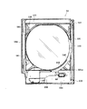
ここで、前述した前面枠セット14について、図1,図5を参照しつつより詳細に説明する。図5は、前面枠セット14の背面図である。前面枠セット14には前記遊技領域のほとんどを外部から視認することができるよう略楕円形状の窓部101が形成されている。詳しくは、窓部101は、その左右側の略中央部が、上下側に比べて比較的緩やかに湾曲した形状となっている。なお、前記略中央部が直線状になるようにしてもよい。本実施の形態において、窓部101の上端(外レール52の最上部、遊技領域の上端)と、前面枠セット14の上端との間の距離(いわゆる上部フレーム部分の上下幅)は61mmとなっており、85mm〜95mm程度上部フレーム幅がある従来技術に比べて著しく短くなっている。これにより、遊技領域の上部領域が確保されやすくなるとともに、大型の可変表示装置ユニット35も比較的上方に配置することができるようになっている。前面枠セット14の上端との間の距離は80mm以下であることが望ましく、より望ましくは70mm以下であり、さらに望ましくは60mm以下である。もちろん、所定の強度が確保できるのであれば、50mm以下であっても差し支えない。   Here, the front frame set 14 described above will be described in more detail with reference to FIGS. FIG. 5 is a rear view of the front frame set 14. The front frame set 14 is formed with a substantially elliptical window 101 so that most of the game area can be viewed from the outside. Specifically, the window portion 101 has a shape in which a substantially central portion on the left and right sides is curved relatively gently as compared with the upper and lower sides. The substantially central portion may be linear. In the present embodiment, the distance between the upper end of the window portion 101 (the uppermost portion of the outer rail 52 and the upper end of the game area) and the upper end of the front frame set 14 (the vertical width of the so-called upper frame portion) is 61 mm. It is significantly shorter than the prior art having an upper frame width of about 85 mm to 95 mm. As a result, the upper area of the game area can be easily secured, and the large-sized variable display device unit 35 can be arranged relatively upward. The distance between the upper end of the front frame set 14 is desirably 80 mm or less, more desirably 70 mm or less, and further desirably 60 mm or less. Of course, as long as a predetermined strength can be ensured, it may be 50 mm or less.

また、パチンコ機10の正面から見て窓部101の左端と前面枠セット14の左端との間の最短距離(いわゆる左側部フレーム部分の左右幅:図5では右側に示されている)、すなわち開閉軸線側のフレーム幅は、前面枠セット14自体の強度及び支持強度を高めるために比較的大きく設定されている。この場合、図1及び図3を相互に比較すると明らかなように、前面枠セット14が閉じられた状態において、外レール52の左端部はもちろん、内レール51の左端部も前記左側部フレーム部分によって覆い隠される。つまり、誘導レールの少なくとも一部が、パチンコ機10の正面からみて前面枠セット14の左側部フレーム部分と重複し覆い隠される。このように遊技球が一時的に視認困難となったとしても、それは、遊技球が遊技領域に案内される通過点に過ぎず、遊技者が主として遊技を楽しむ遊技領域において遊技球が視認困難となるわけではない。そのため、実際の遊技に際しては何ら支障が生じない。また、このような支障が生じない一方で、前面枠セット14の十分な強度及び支持強度が確保可能となっている。ちなみに、パチンコ機10の正面から見て外レール52の左端位置と外枠11の左端位置との左右方向の距離は21mm、遊技領域の右端位置(内レール51の右端位置)と外枠11の右端位置との左右方向の距離は44mmとなっている。   Further, the shortest distance between the left end of the window portion 101 and the left end of the front frame set 14 when viewed from the front of the pachinko machine 10 (the left-right width of the so-called left side frame portion: shown on the right side in FIG. 5), The frame width on the opening / closing axis side is set to be relatively large in order to increase the strength and support strength of the front frame set 14 itself. In this case, as is apparent from a comparison between FIGS. 1 and 3, in the state where the front frame set 14 is closed, not only the left end portion of the outer rail 52 but also the left end portion of the inner rail 51 is the left frame portion. Obscured by. That is, at least a part of the guide rail overlaps and is covered with the left frame portion of the front frame set 14 when viewed from the front of the pachinko machine 10. Even if it becomes difficult to visually recognize the game ball in this way, it is only a passing point where the game ball is guided to the game area, and it is difficult to see the game ball in the game area where the player mainly enjoys the game. It doesn't mean. Therefore, there is no trouble in actual game. Moreover, while such a trouble does not arise, sufficient intensity | strength and support strength of the front frame set 14 are securable. Incidentally, the distance in the left-right direction between the left end position of the outer rail 52 and the left end position of the outer frame 11 when viewed from the front of the pachinko machine 10 is 21 mm, the right end position of the game area (the right end position of the inner rail 51) and the outer frame 11 The distance in the left-right direction with respect to the right end position is 44 mm.

加えて、前面枠セット14にはその周囲(例えばコーナー部分)に各種ランプ等の発光手段が設けられている。これら発光手段は、大当たり時や所定のリーチ時等における遊技状態の変化に応じて点灯、点滅のように発光態様が変更制御され遊技中の演出効果を高める役割を果たすものである。例えば、窓部101の周縁には、LED等の発光手段を内蔵した環状電飾部102が左右対称に設けられ、該環状電飾部102の中央であってパチンコ機10の最上部には、同じくLED等の発光手段を内蔵した中央電飾部103が設けられている。本パチンコ機10では、中央電飾部103が大当たりランプとして機能し、大当たり時に点灯や点滅を行うことにより、大当たり中であることを報知する。さらに、上皿19周りにも、同じくLED等の発光手段を内蔵した上皿電飾部104が設けられている。その他、中央電飾部103の左右側方には、賞球払出し中に点灯する賞球ランプ105と所定のエラー時に点灯するエラー表示ランプ106とが設けられている。また、環状電飾部102の下端部に隣接するようにして、内枠12表面や遊技盤30表面等の一部を視認できるよう透明樹脂からなる小窓107が設けられている。この小窓107の所定箇所を平面状としているので、遊技盤30の右下隅部に貼り付けられた証紙などを、小窓107の当該平面状箇所から機械で好適に読み取ることができる。   In addition, the front frame set 14 is provided with light emitting means such as various lamps in the periphery (for example, corner portion). These light emitting means play a role of enhancing the effect of the game during the game by changing and controlling the light emission mode such as lighting and blinking according to the change of the game state at the time of big hit or predetermined reach. For example, at the periphery of the window portion 101, an annular illumination portion 102 containing light emitting means such as an LED is provided symmetrically, and at the center of the annular illumination portion 102 and at the top of the pachinko machine 10, Similarly, a central illumination unit 103 having a built-in light emitting means such as an LED is provided. In the pachinko machine 10, the central illumination unit 103 functions as a jackpot lamp, and lights and blinks when the jackpot is informed that the jackpot is being hit. Further, an upper plate illumination part 104 that also includes a light emitting means such as an LED is provided around the upper plate 19. In addition, on the left and right sides of the central illumination unit 103, there are provided a prize ball lamp 105 that is lit during the payout of a prize ball and an error display lamp 106 that is lit when a predetermined error occurs. In addition, a small window 107 made of a transparent resin is provided so as to be adjacent to the lower end portion of the annular illumination portion 102 so that a part of the inner frame 12 surface, the game board 30 surface, or the like can be visually recognized. Since the predetermined portion of the small window 107 is flat, the certificate paper or the like attached to the lower right corner of the game board 30 can be suitably read from the flat portion of the small window 107 by a machine.

また、窓部101の下方には貸球操作部120が配設されており、貸球操作部120には球貸しボタン121と、返却ボタン122と、度数表示部123とが設けられている。パチンコ機10の側方に配置された図示しないカードユニット(球貸しユニット)に紙幣やカード等を投入した状態で貸球操作部120が操作されると、その操作に応じて遊技球の貸出が行われる。球貸しボタン121は、カード等(記録媒体)に記録された情報に基づいて貸出球を得るために操作されるものであり、カード等に残額が存在する限りにおいて貸出球が上皿19に供給される。返却ボタン122は、カードユニットに挿入されたカード等の返却を求める際に操作される。度数表示部123はカード等の残額情報を表示するものである。なお、カードユニットを介さずに球貸し装置等から上皿に遊技球が直接貸し出されるパチンコ機、いわゆる現金機では貸球操作部120が不要となる。故に、貸球操作部120の設置部分に、飾りシール等が付されるようになっている。これにより、カードユニットを用いたパチンコ機と現金機との貸球操作部の共通化が図れる。   In addition, a ball lending operation unit 120 is disposed below the window unit 101, and the ball lending operation unit 120 is provided with a ball lending button 121, a return button 122, and a frequency display unit 123. When the ball lending operation unit 120 is operated with a bill or a card inserted in a card unit (ball lending unit) (not shown) arranged on the side of the pachinko machine 10, a game ball is lent according to the operation. Done. The ball lending button 121 is operated to obtain a lending ball based on information recorded on a card or the like (recording medium), and the lending ball is supplied to the upper plate 19 as long as there is a remaining amount on the card or the like. Is done. The return button 122 is operated when requesting the return of a card or the like inserted into the card unit. The frequency display unit 123 displays remaining amount information such as a card. It should be noted that the ball rental operation unit 120 is not necessary for a pachinko machine in which game balls are lent directly to the upper plate from a ball lending device or the like without using a card unit, that is, a so-called cash machine. Therefore, a decorative seal or the like is attached to the installation portion of the ball rental operation unit 120. Thereby, the common use of the lending operation unit of the pachinko machine using the card unit and the cash machine can be achieved.

また、図1に示すように、前面枠セット14の左側の小窓107付近を前面側(図1の紙面手前側)に必要以上に突出しないようにしている。こうすることで、パチンコ機10の左側に設けられたカードサンドの球貸し装置から直接に上皿19に遊技球を貸し出す際に、当該球貸し装置のノーズ部(いわゆる象の鼻)の先端排出口を好適に上皿19の上方位置に位置させることができ、当該球貸し装置のノーズ部から貸し出される遊技球を上皿19で受けることができる。   Further, as shown in FIG. 1, the vicinity of the small window 107 on the left side of the front frame set 14 is not protruded more than necessary to the front side (the front side in FIG. 1). Thus, when a game ball is lent directly to the upper plate 19 from the card sand ball lending device provided on the left side of the pachinko machine 10, the tip of the nose portion (so-called elephant nose) of the ball lending device is discharged. An exit can be suitably located in the upper position of the top plate 19, and the game ball lent from the nose part of the said ball lending apparatus can be received by the top plate 19. FIG.

前面枠セット14の裏側には、窓部101を囲むようにして金属製の各種補強部材が設けられている。詳しくは、図5に示すように、前面枠セット14の裏側にあって窓部101の上下左右の外側にはそれぞれ補強板131,132,133,134が取り付けられている。これら補強板131〜134は相互に接触して連結されているが、図の左側及び上側の補強板132,133の連結部には直接の接触を避けるための樹脂パーツ135が介在されている。このように補強板132,133の連結部に樹脂パーツ135を介在させているので、ノイズが補強板131〜134でループすることを防止できる。また、図5の右側の補強板131にはその中間位置にフック状をなす係合爪131aが設けられており、この係合爪131aは、前面枠セット14を閉じた状態で内枠12の孔部12a(図3参照)に係合されるように構成されている。この構成により、上皿19を含む形態で前面枠セット14が構成され、その上下の軸支位置が延長されたとしても、中間位置における前面枠セット14の浮き上がりが防止できる。それ故、前面枠セット14を浮かしての不正行為等が抑制されるようになっている。   Various reinforcing members made of metal are provided on the back side of the front frame set 14 so as to surround the window portion 101. Specifically, as shown in FIG. 5, reinforcing plates 131, 132, 133, and 134 are respectively attached to the back side of the front frame set 14 and on the top, bottom, left, and right sides of the window portion 101. These reinforcing plates 131 to 134 are connected in contact with each other, but resin parts 135 for avoiding direct contact are interposed at the connecting portions of the left and upper reinforcing plates 132 and 133 in the drawing. Thus, since the resin part 135 is interposed in the connection part of the reinforcement boards 132 and 133, it can prevent that a noise loops with the reinforcement boards 131-134. Further, the right reinforcing plate 131 of FIG. 5 is provided with an engaging claw 131a having a hook shape at an intermediate position thereof, and this engaging claw 131a is formed on the inner frame 12 with the front frame set 14 closed. It is configured to be engaged with the hole 12a (see FIG. 3). With this configuration, the front frame set 14 is configured to include the upper plate 19, and even if the upper and lower pivot support positions are extended, the front frame set 14 can be prevented from being lifted at the intermediate position. Therefore, an illegal act or the like floating the front frame set 14 is suppressed.

また、下側の補強板134には、前記発射レール61(図3参照)に対向する位置に樹脂製のレール側壁部材136が設けられている。このレール側壁部材136は、前面枠セット14を閉じた際に発射レール61の側壁となる。故に、発射レール61から遊技球がこぼれ落ちないようになっている。   The lower reinforcing plate 134 is provided with a resin rail side wall member 136 at a position facing the firing rail 61 (see FIG. 3). The rail side wall member 136 becomes the side wall of the firing rail 61 when the front frame set 14 is closed. Therefore, the game ball is prevented from spilling from the launch rail 61.

上述した補強板131〜134はガラス支持用の金枠としての機能も兼ね備えており、これら補強板131〜134の一部が後方に折り返されてガラス保持溝が形成されている。このガラス保持溝は前後に2列形成されており、矩形状をなす前後一対のガラス137が各ガラス保持溝にて保持される。これにより、2枚のガラス137が前後に所定間隔を隔てて取着されるようになっている。   The reinforcing plates 131 to 134 described above also have a function as a metal frame for supporting the glass, and a part of the reinforcing plates 131 to 134 is folded back to form a glass holding groove. The glass holding grooves are formed in two rows on the front and rear sides, and a pair of front and rear glasses 137 having a rectangular shape are held in each glass holding groove. Thereby, the two glass 137 is attached to the front and back at a predetermined interval.

前述の通り本実施の形態のパチンコ機10では遊技領域の拡張を図っていることから、前面枠セット14を閉じた状態にあっては、内外のレール52,53により構成された誘導レールの一部が前面枠セット14により覆い隠される構成となっている。それ故、当該誘導レールでは手前側の開放部がガラス137で覆えない部分ができてしまう。かかる場合、例えば、遊技球発射装置38より発射された遊技球が戻り球防止部材53まで至らず戻ってくると、当該遊技球が誘導レール外にこぼれたり(飛び出したり)、外レール52とガラス137との間に挟まってしまうおそれがある。そこで本実施の形態では、前面枠セット14に、誘導レールの手前側開放部を被覆するためのレールカバー140を取り付けている。   As described above, in the pachinko machine 10 according to the present embodiment, the game area is expanded. The part is covered with the front frame set 14. Therefore, in the guide rail, a portion where the open side on the front side cannot be covered with the glass 137 is formed. In such a case, for example, when the game ball launched from the game ball launching device 38 returns without reaching the return ball prevention member 53, the game ball spills out (jumps out) from the guide rail, or the outer rail 52 and the glass. 137. Therefore, in the present embodiment, a rail cover 140 for covering the front side open portion of the guide rail is attached to the front frame set 14.

レールカバー140は略円弧状をなす略平板体であって、透明な樹脂により形成されている。レールカバー140は、その円弧形状が前記誘導レールの形状に対応しており、窓部101の周縁部に沿って、誘導レールの基端部から先端部近傍までの区間を覆うようにして前面枠セット14の裏側に取着されている。特にレールカバー140の内径側の寸法・形状は内レール52のそれにほぼ一致する。レールカバー140が取着された状態では、その表面側がガラス137に当接した状態となる。前面枠セット14が閉じられた状態においては、レールカバー140の裏面が誘導レールのほぼ全域を覆うこととなる。これにより、誘導レールのほとんどの区間において遊技球のガラス137への衝突を防止できる。従って、ガラス137への接触による破損等の悪影響を抑制することができる。   The rail cover 140 is a substantially flat plate having a substantially arc shape, and is formed of a transparent resin. The rail cover 140 has an arc shape corresponding to the shape of the guide rail, and covers the section from the base end portion of the guide rail to the vicinity of the tip end portion along the peripheral edge of the window portion 101. It is attached to the back side of the set 14. In particular, the size and shape of the rail cover 140 on the inner diameter side substantially match those of the inner rail 52. When the rail cover 140 is attached, the surface side of the rail cover 140 is in contact with the glass 137. When the front frame set 14 is closed, the back surface of the rail cover 140 covers almost the entire area of the guide rail. Thereby, the collision of the game ball with the glass 137 can be prevented in most sections of the guide rail. Therefore, adverse effects such as breakage due to contact with the glass 137 can be suppressed.

また、レールカバー140の右端部(すなわち、レールカバー140を前面枠セット14に取着した図5の状態で右端となる部位)には、誘導レールがガラス137の側縁部からはみ出した部分を被覆するための被覆部141が設けられている。これにより、遊技球が誘導レール外にこぼれたり(飛び出したり)、外レール52とガラス137との間に挟まってしまうといった不具合の発生を防止することができる。   Further, a portion where the guide rail protrudes from the side edge portion of the glass 137 is provided at the right end portion of the rail cover 140 (that is, the portion which becomes the right end in the state of FIG. 5 where the rail cover 140 is attached to the front frame set 14). A covering portion 141 for covering is provided. Thereby, it is possible to prevent the occurrence of problems such that the game ball spills out of the guide rail (jumps out) or gets caught between the outer rail 52 and the glass 137.

さらに、レールカバー140の裏側には、その内側縁に沿って円弧状に延び且つ図5の手前側に突出した突条142が形成されている。突条142は、前面枠セット14が閉じられた状態において、誘導レール内に入り込んだ状態で内レール52にほぼ一体的に重なり合うよう構成されている。従って、例えば前面枠セット14と内枠12との隙間から針金等を侵入させて不正行為を行おうとしても、誘導レールの内側にある遊技領域にまで針金等を侵入させることが非常に困難となる。結果として、針金等を利用して行われる不正行為を防止することができる。なお、突条142をより広い範囲で、例えばレールカバー140の内側縁の全域に沿って形成する構成としても良く、かかる構成によれば、より広い範囲で針金等を侵入させにくくなり、針金等を利用して行われる不正行為をより確実に防止することができる。   Further, on the back side of the rail cover 140, a ridge 142 is formed that extends in an arc along the inner edge of the rail cover 140 and protrudes toward the front side of FIG. The ridge 142 is configured to overlap the inner rail 52 substantially integrally with the rim 142 in a state of entering the guide rail when the front frame set 14 is closed. Therefore, for example, even if a wire or the like is invaded from the gap between the front frame set 14 and the inner frame 12 to perform a fraud, it is very difficult to infiltrate the wire or the like into the game area inside the guide rail. Become. As a result, fraudulent acts performed using a wire or the like can be prevented. In addition, it is good also as a structure which forms the protrusion 142 in a wider range, for example along the whole region of the inner edge of the rail cover 140. According to this structure, it becomes difficult to infiltrate a wire etc. in a wider range, a wire etc. It is possible to more reliably prevent fraud performed using

また、前面枠セット14の図5の右端部(パチンコ機10正面から見ると左端部)には、内枠12の支持機構として、支持金具151,152が取り付けられている。従って、内枠12側の支持金具81,82(図3参照)に対して前面枠セット14側の支持金具151,152を組み付けることで、内枠12に対して前面枠セット14が開閉可能に装着されるようになる。   Further, support metal fittings 151 and 152 are attached to the right end portion of the front frame set 14 in FIG. 5 (left end portion when viewed from the front of the pachinko machine 10) as a support mechanism for the inner frame 12. Therefore, the front frame set 14 can be opened and closed with respect to the inner frame 12 by assembling the support brackets 151 and 152 on the front frame set 14 side to the support brackets 81 and 82 (see FIG. 3) on the inner frame 12 side. It comes to be installed.

次に、パチンコ機10の背面の構成を詳しく説明する。図6はパチンコ機10の背面図であり、図7はパチンコ機10の背面構成を主要部品毎に分解して示す分解斜視図である。   Next, the configuration of the back surface of the pachinko machine 10 will be described in detail. FIG. 6 is a rear view of the pachinko machine 10, and FIG. 7 is an exploded perspective view showing the rear structure of the pachinko machine 10 for each major part.

先ず、パチンコ機10の背面構成について全体の概要を説明する。パチンコ機10にはその背面(実際には内枠12及び遊技盤30の背面)において、各種制御基板が上下左右に並べられるようにして又は前後に重ねられるようにして配置されており、さらに、遊技球を供給するための遊技球供給装置(払出機構)や樹脂製の保護カバー等が取り付けられている。本実施の形態では、各種制御基板を2つの取付台に分けて搭載して2つの制御基板ユニットを構成し、それら制御基板ユニットを個別に内枠12又は遊技盤30の裏面に装着するようにしている。この場合、主基板と音声ランプ制御基板とを一方の取付台に搭載してユニット化すると共に、払出制御基板、発射制御基板及び電源基板を他方の取付台に搭載してユニット化している。ここでは便宜上、前者のユニットを「第1制御基板ユニット201」と称し、後者のユニットを「第2制御基板ユニット202」と称することとする。   First, an overall outline of the rear configuration of the pachinko machine 10 will be described. In the pachinko machine 10, various control boards are arranged on the back side (actually the back side of the inner frame 12 and the game board 30) so as to be arranged vertically or horizontally, or to be stacked in front and back, A game ball supply device (payout mechanism) for supplying game balls, a protective cover made of resin, and the like are attached. In this embodiment, various control boards are divided into two mounting bases to form two control board units, and these control board units are individually attached to the inner frame 12 or the back of the game board 30. ing. In this case, the main board and the sound lamp control board are mounted on one mounting base to form a unit, and the dispensing control board, launch control board, and power supply board are mounted on the other mounting base to form a unit. Here, for convenience, the former unit is referred to as “first control board unit 201”, and the latter unit is referred to as “second control board unit 202”.

また、払出機構及び保護カバーも1ユニットとして一体化されており、一般に樹脂部分を裏パックと称することもあるため、ここではそのユニットを「裏パックユニット203」と称する。各ユニット201〜203の詳細な構成については後述する。   Further, since the dispensing mechanism and the protective cover are integrated as one unit, and the resin portion is generally referred to as a back pack, the unit is referred to as a “back pack unit 203” here. The detailed configuration of each unit 201 to 203 will be described later.

第1制御基板ユニット201、第2制御基板ユニット202及び裏パックユニット203は、ユニット単位で何ら工具等を用いずに着脱できるよう構成されており、さらにこれに加え、一部に支軸部を設けて内枠12又は遊技盤30の裏面に対して開閉できる構成となっている。これは、各ユニット201〜203やその他構成が前後に重ねて配置されても、隠れた構成等を容易に確認することを可能とするための工夫でもある。   The first control board unit 201, the second control board unit 202, and the back pack unit 203 are configured to be detachable without using any tools or the like in units of units. It is configured to be openable and closable with respect to the inner frame 12 or the back surface of the game board 30. This is also a device for making it possible to easily check a hidden configuration or the like even if the units 201 to 203 and other configurations are arranged one behind the other.

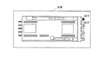
実際には、図8の概略図に示すように各ユニット201〜203が配置され、取り付けられている。なお図8において、略L字状をなす第1制御基板ユニット201はパチンコ機10のほぼ中央に配置され、その下方に第2制御基板ユニット202が配置されている。また、第1制御基板ユニット201に一部重なる領域に、裏パックユニット203が配置されている。   Actually, the units 201 to 203 are arranged and attached as shown in the schematic diagram of FIG. In FIG. 8, the first control board unit 201 having a substantially L shape is arranged at substantially the center of the pachinko machine 10, and the second control board unit 202 is arranged therebelow. Further, the back pack unit 203 is arranged in a region partially overlapping the first control board unit 201.

詳しくは、第1制御基板ユニット201には、パチンコ機10の背面から見て左端部に支軸部M1が設けられ、その支軸部M1による軸線Aを中心に当該第1制御基板ユニット201が開閉可能となっている。また、第1制御基板ユニット201には、その右端部(すなわち支軸部と反対側、さらに言えば開放端側)にナイラッチ等よりなる締結部M2が設けられると共に上端部に係止爪部M3が設けられており、これら締結部M2及び係止爪部M3によって第1制御基板ユニット201がパチンコ機本体に対して固定保持されるようになっている。   Specifically, the first control board unit 201 is provided with a support shaft part M1 at the left end portion when viewed from the back of the pachinko machine 10, and the first control board unit 201 is centered on the axis A by the support shaft part M1. It can be opened and closed. Further, the first control board unit 201 is provided with a fastening portion M2 made of a ny latch or the like at the right end portion thereof (that is, the side opposite to the support shaft portion, more specifically, the open end side), and the locking claw portion M3 at the upper end portion. The first control board unit 201 is fixed and held to the main body of the pachinko machine by the fastening part M2 and the locking claw part M3.

また、第2制御基板ユニット202には、パチンコ機10の背面から見て右端部に支軸部M4が設けられ、その支軸部M4による軸線Bを中心に当該第2制御基板ユニット202が開閉可能となっている。また、第2制御基板ユニット202には、その左端部(すなわち支軸部と反対側、さらに言えば開放端側)にナイラッチ等よりなる締結部M5が設けられており、この締結部M5によって第2制御基板ユニット202がパチンコ機本体に対して固定保持されるようになっている。   Further, the second control board unit 202 is provided with a support shaft part M4 at the right end when viewed from the back of the pachinko machine 10, and the second control board unit 202 opens and closes around the axis B by the support shaft part M4. It is possible. Further, the second control board unit 202 is provided with a fastening portion M5 made of a ny latch or the like at the left end portion thereof (that is, the side opposite to the support shaft portion, more specifically, the open end side). 2 The control board unit 202 is fixedly held to the pachinko machine body.

さらに、裏パックユニット203には、パチンコ機10の背面から見て右端部に支軸部M6が設けられ、その支軸部M6による軸線Cを中心に当該裏パックユニット203が開閉可能となっている。また、裏パックユニット203には、その左端部(すなわち支軸部と反対側、さらに言えば開放端側)にナイラッチ等よりなる締結部M7が設けられると共に上端部及び下端部にそれぞれ回動式の係止部M8,M9が設けられており、これら締結部M7及び係止部M8,M9によって裏パックユニット203がパチンコ機本体に対して固定保持されるようになっている。   Further, the back pack unit 203 is provided with a support shaft portion M6 at the right end when viewed from the back of the pachinko machine 10, and the back pack unit 203 can be opened and closed around the axis C by the support shaft portion M6. Yes. Further, the back pack unit 203 is provided with a fastening portion M7 made of a ny latch or the like on the left end portion thereof (that is, on the side opposite to the support shaft portion, more specifically, on the open end side), and at the upper end portion and the lower end portion, respectively. , And the back pack unit 203 is fixedly held to the main body of the pachinko machine by the fastening part M7 and the locking parts M8, M9.

この場合、各ユニット201〜203の展開方向は同一でなく、第1制御基板ユニット201は、パチンコ機10の背面から見て左開きになるのに対し、第2制御基板ユニット202及び裏パックユニット203は、同右開きになるよう構成されている。   In this case, the development directions of the units 201 to 203 are not the same, and the first control board unit 201 opens to the left when viewed from the back of the pachinko machine 10, whereas the second control board unit 202 and the back pack unit. 203 is configured to open to the right.

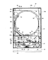
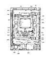
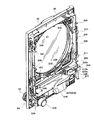
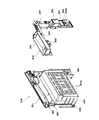
一方、図9は、内枠12に遊技盤30を組み付けた状態でその構成を示す背面図である。また、図10は内枠12を後方より見た斜視図であり、図11は遊技盤30を後方より見た斜視図である。ここでは図9〜図11を用いて内枠12及び遊技盤30の裏面構成を説明する。   On the other hand, FIG. 9 is a rear view showing the configuration in a state where the game board 30 is assembled to the inner frame 12. FIG. 10 is a perspective view of the inner frame 12 as viewed from the rear, and FIG. 11 is a perspective view of the game board 30 as viewed from the rear. Here, the backside structure of the inner frame 12 and the game board 30 will be described with reference to FIGS.

遊技盤30は、樹脂ベース20に囲まれた四角枠状の設置領域に設置され、内枠12に設けられた複数(本実施の形態では4カ所)の係止固定具211,212によって脱落しないように固定されている。係止固定具211,212は手動で回動でき、固定位置(ロック位置)と固定解除位置(アンロック位置)とを切り換えることができるよう構成されており、図9にはロック状態を示す。遊技盤30の左右3カ所の係止固定具211は金属片を折り曲げ形成したL型の金具であり、遊技盤30の固定状態で内枠外方へ張り出さないよう構成されている。なお、遊技盤30の下部1カ所の係止固定具212は樹脂製のI型の留め具である。   The game board 30 is installed in a square frame-shaped installation area surrounded by the resin base 20 and is not dropped by a plurality of (four in this embodiment) locking fixtures 211 and 212 provided on the inner frame 12. So that it is fixed. The locking fixtures 211 and 212 can be manually rotated to switch between a fixed position (lock position) and a fixed release position (unlock position). FIG. 9 shows a locked state. The locking fixtures 211 at the three left and right sides of the game board 30 are L-shaped brackets formed by bending metal pieces, and are configured not to protrude outward from the inner frame when the game board 30 is fixed. Note that the locking fixture 212 at one lower portion of the game board 30 is an I-shaped fastener made of resin.

遊技盤30の中央には可変表示装置ユニット35が配置されている。可変表示装置ユニット35においては、センターフレーム47(図3参照)を背後から覆う樹脂製(例えばABS製)のフレームカバー213が後方に突出して設けられており、そのフレームカバー213の後端に、液晶表示装置たる第1図柄表示装置42と表示制御装置45とが前後に重ねられた状態で着脱可能に取り付けられている。フレームカバー213内には、センターフレーム47に内蔵されたLED等を駆動するためのLED制御基板などが配設されている。   A variable display device unit 35 is disposed in the center of the game board 30. In the variable display device unit 35, a frame cover 213 made of resin (for example, made of ABS) that covers the center frame 47 (see FIG. 3) from behind is provided to protrude rearward, and at the rear end of the frame cover 213, The 1st symbol display apparatus 42 and the display control apparatus 45 which are liquid crystal display devices are attached so that attachment or detachment is possible in the state piled up back and forth. In the frame cover 213, an LED control board for driving LEDs and the like built in the center frame 47 are disposed.

また、遊技盤30の裏面には、可変表示装置ユニット35を取り囲むようにして裏枠セット215が取り付けられている。この裏枠セット215は、遊技盤30の裏面に張り付くようにして設けられる薄型の樹脂成型品(例えばABS製)であって、各種入賞口に入賞した遊技球を回収するための遊技球回収機構が形成されている。詳しくは、裏枠セット215の下方には、前述した一般入賞口31、可変入賞装置32、第1の始動口33(それぞれ図3参照)の遊技盤開口部に対応し、且つ下流側で1カ所に集合する回収通路216が形成されている。また、遊技盤30の下方には、内枠12にやはり樹脂製(例えばポリカーボネート樹脂製)の排出通路盤217が取り付けられており、該排出通路盤217には、排出球をパチンコ機10外部へ案内するための排出通路218が形成されている。従って、図9に仮想線で例示するように、一般入賞口31等に入賞した遊技球は何れも裏枠セット215の回収通路216を介して集合し、さらに排出通路盤217の排出通路218を介してパチンコ機10外部に排出される。なお、アウト口36(図3参照)も同様に排出通路218に通じており、何れの入賞口にも入賞しなかった遊技球も排出通路218を介してパチンコ機10外部に排出される。   A back frame set 215 is attached to the back surface of the game board 30 so as to surround the variable display device unit 35. The back frame set 215 is a thin resin-molded product (for example, made of ABS) provided so as to stick to the back surface of the game board 30, and a game ball collecting mechanism for collecting game balls won in various winning openings. Is formed. Specifically, below the back frame set 215, corresponding to the game board opening of the above-described general winning port 31, variable winning device 32, and first starting port 33 (see FIG. 3 respectively), and 1 on the downstream side. A collection passage 216 that collects at a place is formed. Further, a discharge passage board 217 made of resin (for example, made of polycarbonate resin) is attached to the inner frame 12 below the game board 30, and a discharge ball is sent to the outside of the pachinko machine 10 in the discharge passage board 217. A discharge passage 218 for guiding is formed. Therefore, as illustrated in phantom lines in FIG. 9, all the game balls won in the general winning opening 31 etc. gather through the collection passage 216 of the back frame set 215, and further the discharge passage 218 of the discharge passage board 217. Through the pachinko machine 10. In addition, the out port 36 (see FIG. 3) similarly communicates with the discharge passage 218, and the game balls that have not won any prize opening are discharged to the outside of the pachinko machine 10 through the discharge passage 218.

上記構成では、遊技盤30の下端面を境界にして、上方に裏枠セット215(回収通路216)が、下方に排出通路盤217(排出通路218)が設けられており、排出通路盤217が遊技盤30に対して前後方向に重複(オーバーラップ)せずに設けられている。従って、遊技盤30を内枠12から取り外す際において、排出通路盤217が遊技盤取り外しの妨げになるといった不都合が生じることもない。   In the above configuration, with the lower end surface of the game board 30 as a boundary, a back frame set 215 (collection passage 216) is provided above, and a discharge passage board 217 (discharge passage 218) is provided below. The game board 30 is provided without overlapping (overlapping) in the front-rear direction. Therefore, when removing the game board 30 from the inner frame 12, there is no inconvenience that the discharge passage board 217 prevents the game board from being removed.

なお、排出通路盤217は、パチンコ機前面の上皿19の丁度裏側辺りに設けられており、上皿19に至る球排出口(図2の球通路樋69)より針金等を差し込み、さらにその針金等を内枠12と排出通路盤217との隙間を通じて遊技領域側に侵入させるといった不正行為が考えられる。そこで本パチンコ機10では、排出通路盤217の上皿19の丁度裏側辺りに、内枠12にほぼ一体的に重なり合うようにしてパチンコ機前方に延びるプレート219が設けられている。従って、内枠12と排出通路盤217との隙間から針金等を侵入させようとしてもそれがプレート219にて阻害され、遊技領域にまで針金等を侵入させることが非常に困難となる。結果として、針金等を利用して可変入賞装置32(大入賞口)を強制的に開放する等の不正行為を防止することができる。   The discharge passage board 217 is provided just behind the upper plate 19 on the front surface of the pachinko machine. A wire or the like is inserted from a ball discharge port (ball passage rod 69 in FIG. 2) leading to the upper plate 19, An illegal act of causing a wire or the like to enter the game area side through a gap between the inner frame 12 and the discharge passage board 217 can be considered. Accordingly, in the pachinko machine 10, a plate 219 extending in front of the pachinko machine so as to overlap the inner frame 12 almost integrally is provided just behind the upper plate 19 of the discharge passage board 217. Therefore, even if a wire or the like tries to enter from the gap between the inner frame 12 and the discharge passage board 217, the wire or the like is obstructed by the plate 219, and it becomes very difficult to make the wire or the like enter the game area. As a result, it is possible to prevent an illegal act such as forcibly opening the variable winning device 32 (large winning opening) using a wire or the like.

また、遊技盤30の裏面には、各種入賞口などの遊技球の通過を検出するための入賞感知機構などが設けられている。具体的には、遊技盤30表側の一般入賞口31に対応する位置には入賞口スイッチ221が設けられ、可変入賞装置32には、特定領域スイッチ222とカウントスイッチ223とが設けられている。特定領域スイッチ222は、大当たり状態で可変入賞装置32に入賞した遊技球が特定領域(大当たり状態継続を判定するための領域)に入ったことを判定するスイッチであり、カウントスイッチ223は入賞球をカウントするスイッチである。また、第1の始動口33に対応する位置には作動口スイッチ224が設けられ、第2の始動口34に対応する位置にはゲートスイッチ225が設けられている。なお、上述した作動口スイッチ224が本発明における入賞検出手段に相当する。   In addition, on the back surface of the game board 30, a winning detection mechanism for detecting the passage of game balls such as various winning holes is provided. Specifically, a prize opening switch 221 is provided at a position corresponding to the general prize opening 31 on the front side of the game board 30, and a specific area switch 222 and a count switch 223 are provided in the variable prize winning device 32. The specific area switch 222 is a switch for determining that a game ball won in the variable winning device 32 in the big hit state has entered a specific area (an area for determining whether or not to continue the big hit state), and the count switch 223 displays the winning ball. It is a switch to count. An operation port switch 224 is provided at a position corresponding to the first start port 33, and a gate switch 225 is provided at a position corresponding to the second start port 34. The operating port switch 224 described above corresponds to the winning detection means in the present invention.

入賞口スイッチ221及びゲートスイッチ225は、図示しない電気配線を通じて盤面中継基板226に接続され、さらにこの盤面中継基板226が後述する主基板(主制御装置)に接続されている。また、特定領域スイッチ222及びカウントスイッチ223は大入賞口中継基板227に接続され、さらにこの大入賞口中継基板227がやはり主基板に接続されている。これに対し、作動口スイッチ224は中継基板を介さずに直接主基板に接続されている。   The prize opening switch 221 and the gate switch 225 are connected to the board relay board 226 through electric wiring (not shown), and the board relay board 226 is further connected to a main board (main control device) described later. Further, the specific area switch 222 and the count switch 223 are connected to the special winning opening relay board 227, and the special winning opening relay board 227 is also connected to the main board. On the other hand, the operation port switch 224 is directly connected to the main board without passing through the relay board.

その他図示は省略するが、可変入賞装置32には、大入賞口を開放するための大入賞口ソレノイドと、入賞球を特定領域に導くための入賞球振分板ソレノイドが設けられ、第1の始動口33には、電動役物を開放するための作動口ソレノイドが設けられている。なお、図9において符号228は打球槌等を備えるセットハンドルであり、符号229は発射モータである。   Although not shown in the drawings, the variable prize winning device 32 is provided with a big prize opening solenoid for opening the big prize opening and a winning ball distribution plate solenoid for guiding the winning ball to a specific area. The starting port 33 is provided with an operating port solenoid for opening the electric accessory. In FIG. 9, reference numeral 228 denotes a set handle including a hitting ball and the like, and reference numeral 229 denotes a firing motor.

上記入賞感知機構にて各々検出された検出結果は、後述する主基板に取り込まれ、該主基板よりその都度の入賞状況に応じた払出指令(遊技球の払出個数)が払出制御基板に送信される。そして、該払出制御基板の出力により所定数の遊技球の払出が実施される。かかる場合、各種入賞口に入賞した遊技球を入賞球処理装置に一旦集め、その入賞球処理装置で入賞球の存在を1つずつ順番に確認した上で払出を行う従来方式(いわゆる証拠球方式)とは異なり、本実施の形態のパチンコ機10では、各種入賞口毎に遊技球の入賞を電気的に感知して払出が直ちに行われる(すなわち、本パチンコ機10では入賞球処理装置を廃止している)。故に、払い出す遊技球が多量にあっても、その払出をいち早く実施することが可能となる。但し、本発明に従来の「証拠球方式」を適用してもよい。   The detection results detected by the winning detection mechanism are taken into the main board, which will be described later, and a payout command (the number of game balls to be paid out) corresponding to the winning situation is sent from the main board to the payout control board. The Then, a predetermined number of game balls are paid out by the output of the payout control board. In such a case, a conventional method (so-called evidence ball method) in which game balls won at various winning openings are once collected in a winning ball processing device, and the winning ball processing device confirms the presence of the winning balls one by one and then pays out one by one. Unlike the above, the pachinko machine 10 according to the present embodiment electrically senses the winning of a game ball at each winning opening and immediately pays out (that is, the pachinko machine 10 abolishes the winning ball processing device). doing). Therefore, even if there are a lot of game balls to be paid out, the payout can be carried out quickly. However, the conventional “evidence ball system” may be applied to the present invention.

また、裏枠セット215には、第1制御基板ユニット201を取り付けるための取付機構が設けられている。具体的には、この取付機構として、遊技盤30の裏面から見て左下隅部には上下方向に延びる支持金具231が設けられ、この支持金具231には同一軸線上に上下一対の支持孔231aが形成されている。その他、遊技盤30の右下部において符号232は上下一対の被締結孔(ナイラッチ孔)であり、同左上部において符号233は係止爪片である。   The back frame set 215 is provided with an attachment mechanism for attaching the first control board unit 201. Specifically, as this mounting mechanism, a support bracket 231 extending in the vertical direction is provided at the lower left corner portion when viewed from the back surface of the game board 30, and the support bracket 231 has a pair of upper and lower support holes 231 a on the same axis. Is formed. In addition, in the lower right part of the game board 30, reference numeral 232 is a pair of upper and lower fastening holes (ny latch holes), and in the upper left part, reference numeral 233 is a locking claw piece.

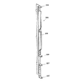
また、内枠12の裏面には、第2制御基板ユニット202や裏パックユニット203を取り付けるための取付機構が設けられている。具体的には、内枠12にはその右端部に長尺状の支持金具235が取り付けられており、その構成を図12に示す。図12に示すように、支持金具235は長尺板状の金具本体236を有し、その金具本体236より起立させるようにして、下方2カ所に第2制御基板ユニット用の支持孔部237が形成されると共に、上方2カ所に裏パックユニット用の支持孔部238が形成されている。それら支持孔部237,238にはそれぞれ同軸の支持孔が形成されている。その他、第2制御基板ユニット用の取付機構として、内枠12には、遊技盤設置領域よりも下方左端部に上下一対の被締結孔(ナイラッチ孔)239が設けられている。また、裏パックユニット用の取付機構として、内枠12には、遊技盤設置領域の左端部に上下一対の被締結孔(ナイラッチ孔)240が設けられている。但し、第2制御基板ユニット用の支持金具と裏パックユニット用の支持金具とを各々個別の部材で設けることも可能である。符号241,242,243は、遊技盤30との間に裏パックユニット203を挟み込んで支持するための回動式の固定具である。   An attachment mechanism for attaching the second control board unit 202 and the back pack unit 203 is provided on the back surface of the inner frame 12. Specifically, a long support fitting 235 is attached to the right end of the inner frame 12, and the configuration is shown in FIG. As shown in FIG. 12, the support metal fitting 235 has a long plate-like metal fitting body 236, and the support hole 237 for the second control board unit is formed at two lower positions so as to stand up from the metal fitting body 236. At the same time, support hole portions 238 for the back pack unit are formed at two upper positions. Coaxial support holes are formed in the support hole portions 237 and 238, respectively. In addition, as an attachment mechanism for the second control board unit, the inner frame 12 is provided with a pair of upper and lower fastening holes (ny latch holes) 239 at the left end below the game board installation area. As a mounting mechanism for the back pack unit, the inner frame 12 is provided with a pair of upper and lower fastening holes (nylatching holes) 240 at the left end of the game board installation area. However, the support bracket for the second control board unit and the support bracket for the back pack unit can be provided as separate members. Reference numerals 241, 242, and 243 denote rotational fixtures for sandwiching and supporting the back pack unit 203 with the game board 30.

その他、内枠12の背面構成において、遊技盤30の右下部には、後述する払出機構部352より払い出される遊技球を上皿19、下皿15、又は排出通路218の何れかに振り分けるための遊技球分配部245が設けられている。すなわち、遊技球分配部245の開口部245aは上皿19に通じ、開口部245bは下皿15に通じ、開口部245cは排出通路218に通じる構成となっている。図10,20に示すように、遊技球分配部245は、その上方位置に位置する後述の払出機構部352とは別体としている。図10に示すように、遊技球分配部245は、内枠12にネジで締結固定されており、パチンコ機10の上皿19の排出口67(図3参照)から異物を挿入操作するなどしても動かない、つまり遊技球分配部245が奥側に押されて遊技球分配部245と内枠12との間に隙間が空くようなことが無いし、この隙間に異物を挿入するなどによる不正を防止できる。   In addition, in the rear configuration of the inner frame 12, a game ball paid out from a payout mechanism portion 352 described later is distributed to any one of the upper plate 19, the lower plate 15, and the discharge passage 218 in the lower right portion of the game board 30. A game ball distribution unit 245 is provided. In other words, the opening 245 a of the game ball distribution unit 245 communicates with the upper plate 19, the opening 245 b communicates with the lower plate 15, and the opening 245 c communicates with the discharge passage 218. As shown in FIGS. 10 and 20, the game ball distribution unit 245 is separated from a later-described payout mechanism unit 352 located above the game ball distribution unit 245. As shown in FIG. 10, the game ball distributing unit 245 is fastened and fixed to the inner frame 12 with screws, and inserts foreign objects from the discharge port 67 (see FIG. 3) of the upper plate 19 of the pachinko machine 10. Even if the game ball distribution unit 245 is pushed to the back side, there is no gap between the game ball distribution unit 245 and the inner frame 12, and a foreign object is inserted into the gap. It can prevent fraud.

また、内枠12の下端部には、下皿15に設置されたスピーカ24の背後を囲むための樹脂製のスピーカボックス246が取り付けられており、このスピーカボックス246により低音域の音質改善が図られている。   In addition, a resin speaker box 246 for surrounding the back of the speaker 24 installed on the lower plate 15 is attached to the lower end portion of the inner frame 12, and the speaker box 246 improves the sound quality in the low frequency range. It has been.

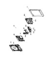
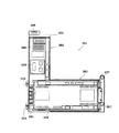
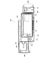
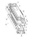
次に、第1制御基板ユニット201を、図13〜図16を用いて説明する。図13は第1制御基板ユニット201の正面図、図14は同ユニット201の斜視図、図15は同ユニット201の分解斜視図、図16は同ユニット201を裏面から見た分解斜視図である。   Next, the first control board unit 201 will be described with reference to FIGS. 13 is a front view of the first control board unit 201, FIG. 14 is a perspective view of the unit 201, FIG. 15 is an exploded perspective view of the unit 201, and FIG. 16 is an exploded perspective view of the unit 201 viewed from the back. .

第1制御基板ユニット201は略L字状をなす取付台251を有し、この取付台251に主制御装置261と音声ランプ制御装置262とが搭載されている。ここで、主制御装置261は、主たる制御を司るCPU、遊技プログラムを記憶したROM、遊技の進行に応じた必要なデータを記憶するRAM、各種機器との連絡をとるポート、各種抽選の際に用いられる乱数発生器、時間計数や同期を図る場合などに使用されるクロックパルス発生回路等を含む主基板を具備しており、この主基板が透明樹脂材料等よりなる基板ボックス263(被包手段)に収容されて構成されている。なお、基板ボックス263は、略直方体形状のボックスベースと該ボックスベースの開口部を覆うボックスカバーとを備えている。これらボックスベースとボックスカバーとは封印ユニット264(封印手段)によって開封不能に連結され、これにより基板ボックス263が封印されている。   The first control board unit 201 includes a mounting base 251 having a substantially L shape, and the main control device 261 and the sound lamp control device 262 are mounted on the mounting base 251. Here, the main control device 261 includes a CPU that controls the main control, a ROM that stores a game program, a RAM that stores necessary data according to the progress of the game, a port that communicates with various devices, and various lotteries. A main board including a random number generator used, a clock pulse generation circuit used for time counting and synchronization, etc., and the main board is made of a transparent resin material or the like; ). The substrate box 263 includes a substantially rectangular parallelepiped box base and a box cover that covers the opening of the box base. The box base and the box cover are connected to each other by a sealing unit 264 (sealing means) so that the box box 263 is sealed.

封印手段としての封印ユニット264はボックスベースとボックスカバーとを開封不能に連結する構成であれば任意の構成が適用できるが、ここでは図14等に示すように、5つの封印部材が連結された構成となっており、この封印部材の長孔に係止爪を挿入することでボックスベースとボックスカバーとが開封不能に連結されるようになっている。封印ユニット264による封印処理は、その封印後の不正な開封を防止し、また万一不正開封が行われてもそのような事態を早期に且つ容易に発見可能とするものであって、一旦開封した後でも再度開封・封印処理を行うこと自体は可能である。すなわち、封印ユニット264を構成する5つの封印部材のうち、少なくとも一つの封印部材の長孔に係止爪を挿入することにより封印処理が行われる。そして、収容した主基板の不具合などにより基板ボックス263を開封する場合には、係止爪が挿入された封印部材と他の封印部材との連結を切断する。その後、再度封印処理する場合は他の封印部材の長孔に係止爪を挿入する。基板ボックス263の開封を行った旨の履歴を当該基板ボックス263に残しておけば、基板ボックス263を見ることで不正な開封が行われた旨が容易に発見できる。   As the sealing unit 264 as the sealing means, any configuration can be applied as long as the box base and the box cover are connected so as not to be opened, but here, as shown in FIG. 14 and the like, five sealing members are connected. The box base and the box cover are connected so that they cannot be opened by inserting a locking claw into the long hole of the sealing member. The sealing process by the sealing unit 264 prevents unauthorized opening after the sealing, and makes it possible to detect such a situation early and easily even if the unauthorized opening is performed. It is possible to perform the opening / sealing process again even after the operation. That is, the sealing process is performed by inserting the locking claw into the long hole of at least one sealing member among the five sealing members constituting the sealing unit 264. And when opening the board | substrate box 263 by the malfunction of the accommodated main board | substrate etc., the connection of the sealing member in which the latching claw was inserted, and another sealing member is cut | disconnected. Thereafter, when the sealing process is performed again, the locking claws are inserted into the long holes of the other sealing members. If the history of opening the board box 263 is left in the board box 263, it can be easily found that the illegal opening has been performed by looking at the board box 263.

また、音声ランプ制御装置262は、例えば主制御装置261(主基板)又は表示制御装置45からの指示に従い音声やランプ表示の制御を司るCPUや、その他ROM、RAM、各種ポート等を含む音声ランプ制御基板を具備しており、この音声ランプ制御基板が透明樹脂材料等よりなる基板ボックス265に収容されて構成されている。音声ランプ制御装置262上には電源中継基板266が搭載されており、後述する電源基板より供給される電源がこの電源中継基板266を介して表示制御装置45及び音声ランプ制御装置262に出力されるようになっている。   The voice lamp control device 262 is a voice lamp including, for example, a CPU that controls voice and lamp display in accordance with instructions from the main control device 261 (main board) or the display control device 45, and other ROM, RAM, various ports, and the like. The audio lamp control board is housed in a board box 265 made of a transparent resin material or the like. A power relay board 266 is mounted on the sound lamp control device 262, and power supplied from a power board described later is output to the display control device 45 and the sound lamp control device 262 via the power relay board 266. It is like that.

取付台251は、有色(例えば緑、青等)の樹脂材料(例えばポリカーボネート樹脂製)にて成形され、その表面に平坦状をなす2つの基板搭載面252,253が設けられている。これら基板搭載面252,253は直交する向きに延び、前後方向に段差をもって形成されている。但し、取付台251は無色透明又は半透明の樹脂成型品であっても良い。   The mounting base 251 is formed of a colored (for example, green, blue, etc.) resin material (for example, made of polycarbonate resin), and has two substrate mounting surfaces 252 and 253 that are flat on the surface. These substrate mounting surfaces 252 and 253 extend in a direction orthogonal to each other, and are formed with a step in the front-rear direction. However, the mounting base 251 may be a colorless transparent or translucent resin molded product.

そして、一方の基板搭載面252上に主制御装置261(主基板)が横長の向きに配置されると共に、他方の基板搭載面253上に音声ランプ制御装置262(音声ランプ制御基板)が縦長の向きに配置されるようになっている。特に、主制御装置261は、パチンコ機10裏面から見て手前側に配置され、音声ランプ制御装置262はその奥側に配置される。この場合、基板搭載面252,253が前後方向に段差をもって形成されているため、これら基板搭載面252,253に主制御装置261及び音声ランプ制御装置262を搭載した状態において各制御装置261,262はその一部を前後に重ねて配置されるようになる。つまり、図14等にも見られるように、主制御装置261はその一部(本実施の形態では1/3程度)が浮いた状態で配置されるようになる。故に、主制御装置261に重なる領域まで音声ランプ制御装置262を拡張することが可能となり、当該制御基板の大型化にも良好に対処できる。また、各制御装置が効率良く設置できるようになる。また、第1制御基板ユニット201を遊技盤30に装着した状態では、基板搭載面252の後方にスペースが確保され、可変入賞装置32やその電気配線等が無理なく設置できるようになっている。   The main control device 261 (main substrate) is arranged in a landscape orientation on one board mounting surface 252 and the audio lamp control device 262 (audio lamp control board) is arranged in a portrait orientation on the other substrate mounting surface 253. It is arranged in the direction. In particular, the main control device 261 is disposed on the near side as viewed from the back of the pachinko machine 10, and the sound lamp control device 262 is disposed on the back side. In this case, since the substrate mounting surfaces 252 and 253 are formed with steps in the front-rear direction, the control devices 261 and 262 are mounted with the main controller 261 and the sound lamp controller 262 mounted on the substrate mounting surfaces 252 and 253. Are arranged with a part of them stacked one after another. That is, as can be seen in FIG. 14 and the like, the main controller 261 is arranged in a state where a part (about 1/3 in the present embodiment) is floated. Therefore, the sound lamp control device 262 can be expanded to an area overlapping with the main control device 261, and the enlargement of the control board can be dealt with satisfactorily. Also, each control device can be installed efficiently. Further, when the first control board unit 201 is mounted on the game board 30, a space is secured behind the board mounting surface 252 so that the variable winning device 32 and its electric wiring can be installed without difficulty.

図15及び図16に示すように、主基板用の基板搭載面252には、左右2カ所に横長形状の貫通孔254が形成されている。これに対応して、主制御装置261の基板ボックス263には、その裏面の左右2カ所に回動式の固定具267が設けられている。主制御装置261を基板搭載面252に搭載する際には、基板搭載面252の貫通孔254に固定具267が通され、その状態で固定具267が回動されて主制御装置261がロックされる。従って、上述の通り主制御装置261はその一部が浮いた状態で配置されるとしても、当該主制御装置261の脱落等の不都合が回避できる。また、主制御装置261は、裏パックユニット203を軸線Cを軸心として開き、第1制御基板ユニット201を軸線Aを軸心として開いた後に、この第1制御基板ユニット201(基板搭載面252)の裏面側から固定具267をロック解除しなければ、取り外しできないため、基板取り外し等の不正行為に対して抑止効果が期待できる。主基板用の基板搭載面252にはその裏面に格子状のリブ255が設けられている。   As shown in FIGS. 15 and 16, the board mounting surface 252 for the main board is formed with horizontally elongated through holes 254 at two places on the left and right. Correspondingly, the substrate box 263 of the main control device 261 is provided with rotational fixing tools 267 at two places on the left and right sides of the back surface thereof. When the main controller 261 is mounted on the board mounting surface 252, the fixing tool 267 is passed through the through hole 254 of the board mounting surface 252, and the fixing tool 267 is rotated in this state to lock the main control apparatus 261. The Therefore, even if the main control device 261 is arranged in a state where it floats as described above, inconveniences such as dropping off of the main control device 261 can be avoided. Further, the main control device 261 opens the back pack unit 203 with the axis C as the axis and opens the first control board unit 201 with the axis A as the axis. ) Cannot be removed unless the lock 267 is unlocked from the back side, so that a deterrent effect can be expected against illegal acts such as board removal. A grid-like rib 255 is provided on the back surface of the substrate mounting surface 252 for the main substrate.

取付台251には、図14等の左端面に上下一対の支軸256が設けられており、この支軸256を図9等に示す支持金具231に取り付けることで、第1制御基板ユニット201が遊技盤30に対して開閉可能に支持される。また、取付台251には、右端部に締結具として上下一対のナイラッチ257が設けられると共に上端部に長孔258が設けられており、ナイラッチ257を図9等に示す被締結孔232にはめ込むと共に、長孔258に図9等に示す係止爪片233を係止させることで、第1制御基板ユニット201が遊技盤30に固定されるようになる。なお、支持金具231及び支軸256が前記図8の支軸部M1に、被締結孔232及びナイラッチ257が締結部M2に、係止爪片233及び長孔258が係止爪部M3に、それぞれ相当する。   The mounting base 251 is provided with a pair of upper and lower support shafts 256 on the left end surface of FIG. 14 and the like. The game board 30 is supported to be openable and closable. Further, the mounting base 251 is provided with a pair of upper and lower nai latches 257 as fasteners at the right end portion and a long hole 258 at the upper end portion, and the nai latch 257 is fitted into the fastening hole 232 shown in FIG. The first control board unit 201 is fixed to the game board 30 by locking the locking claw pieces 233 shown in FIG. The support fitting 231 and the support shaft 256 are in the support shaft portion M1 of FIG. Each corresponds.

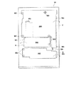
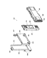
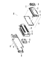
次に、第2制御基板ユニット202を、図17〜図19を用いて説明する。図17は第2制御基板ユニット202の正面図、図18は同ユニット202の斜視図、図19は同ユニット202の分解斜視図である。但し、図18では便宜上、カードユニット接続基板314が取付台301から取り外された状態を示している。   Next, the second control board unit 202 will be described with reference to FIGS. 17 is a front view of the second control board unit 202, FIG. 18 is a perspective view of the unit 202, and FIG. 19 is an exploded perspective view of the unit 202. However, FIG. 18 shows a state in which the card unit connection board 314 is removed from the mounting base 301 for convenience.

第2制御基板ユニット202は横長形状をなす取付台301を有し、この取付台301に払出制御装置311、発射制御装置312、電源装置313及びカードユニット接続基板314が搭載されている。払出制御装置311、発射制御装置312及び電源装置313は周知の通り制御の中枢をなすCPUや、その他ROM、RAM、各種ポート等を含む制御基板を具備しており、払出制御装置311の払出制御基板により、賞品球や貸出球の払出が制御される。また、発射制御装置312の発射制御基板により、遊技者による遊技球発射ハンドル18の操作に従い発射モータ229の制御が行われ、電源装置313の電源基板により、各種制御装置等で要する所定の電源電圧が生成され出力される。カードユニット接続基板314は、パチンコ機前面の貸球操作部120(図1参照)及び図示しないカードユニットに電気的に接続され、遊技者による球貸し操作の指令を取り込んでそれを払出制御装置311に出力するものである。なお、カードユニットを介さずに球貸し装置等から上皿に遊技球が直接貸し出される現金機では、カードユニット接続基板314は不要である。   The second control board unit 202 has a horizontally long mounting base 301 on which a payout control device 311, a firing control device 312, a power supply device 313 and a card unit connection board 314 are mounted. The payout control device 311, the launch control device 312, and the power supply device 313 are equipped with a control board including a central control CPU, ROM, RAM, various ports and the like as is well known. The payout of prize balls and rental balls is controlled by the substrate. The launch control board of the launch control apparatus 312 controls the launch motor 229 in accordance with the operation of the game ball launch handle 18 by the player, and the power supply board of the power supply apparatus 313 provides a predetermined power supply voltage required by various control apparatuses. Is generated and output. The card unit connection board 314 is electrically connected to the ball lending operation unit 120 (see FIG. 1) on the front surface of the pachinko machine and a card unit (not shown), and receives a ball lending operation command by the player and pays it out. Is output. Note that the card unit connection board 314 is not necessary in a cash machine in which game balls are rented directly from the ball lending device or the like to the upper plate without using a card unit.

上記払出制御装置311、発射制御装置312、電源装置313及びカードユニット接続基板314は、透明樹脂材料等よりなる基板ボックス315,316,317,318にそれぞれ収容されて構成されている。特に、払出制御装置311では、前述した主制御装置261と同様、基板ボックス315(被包手段)を構成するボックスベースとボックスカバーとが封印ユニット319(封印手段)によって開封不能に連結され、これにより基板ボックス315が封印されている。   The payout control device 311, the firing control device 312, the power supply device 313, and the card unit connection substrate 314 are respectively configured to be accommodated in substrate boxes 315, 316, 317, and 318 made of a transparent resin material or the like. In particular, in the dispensing control device 311, similarly to the main control device 261 described above, the box base and the box cover constituting the substrate box 315 (encapsulating means) are connected by the sealing unit 319 (sealing means) so that they cannot be opened. Thus, the substrate box 315 is sealed.

払出制御装置311には状態復帰スイッチ321が設けられている。例えば、払出モータ部の球詰まり等、払出エラーの発生時において状態復帰スイッチ321が押下されると、払出モータが正逆回転され、球詰まりの解消(正常状態への復帰)が図られるようになっている。   The payout control device 311 is provided with a state return switch 321. For example, when the state return switch 321 is pressed when a payout error occurs, such as a ball jam in the payout motor unit, the payout motor is rotated forward and reverse so that the ball jam is eliminated (return to the normal state). It has become.

また、電源装置313にはRAM消去スイッチ323が設けられている。本パチンコ機10はバックアップ機能を有しており、万一停電が発生した際でも停電時の状態を保持し、停電からの復帰(復電)の際には停電時の状態に復帰できるようになっている。従って、通常手順で(例えばホールの営業終了時に)電源遮断すると電源遮断前の状態が記憶保持されることから、電源投入時に初期状態に戻したい場合には、RAM消去スイッチ323を押しながら電源を投入することとしている。   Further, the power supply device 313 is provided with a RAM erase switch 323. This pachinko machine 10 has a backup function, so that even if a power failure occurs, it maintains the state at the time of a power failure, and can be restored to the state at the time of a power failure when returning from a power failure (power recovery) It has become. Therefore, if the power is turned off in the normal procedure (for example, when the hall is closed), the state before the power is turned off is stored. If you want to return to the initial state when the power is turned on, turn on the power while holding down the RAM erase switch 323. We are going to throw it in.

取付台301は例えば無色透明な樹脂成型品よりなり、その表面に平坦状をなす基板搭載面302が設けられている。この場合、発射制御装置312、電源装置313及びカードユニット接続基板314は取付台301の基板搭載面302に横並びの状態で直接搭載され、電源装置313の基板ボックス317上に払出制御装置311が搭載されている。   The mounting base 301 is made of, for example, a colorless and transparent resin molded product, and a flat board mounting surface 302 is provided on the surface thereof. In this case, the launch control device 312, the power supply device 313 and the card unit connection board 314 are directly mounted side by side on the board mounting surface 302 of the mounting base 301, and the payout control apparatus 311 is mounted on the board box 317 of the power supply apparatus 313. Has been.

また、取付台301には、図17等の右端部に上下一対の支軸305が設けられており、この支軸305を図9等に示す支持孔部237に上方から挿通させることで、第2制御基板ユニット202が内枠12に対して開閉可能に支持される。また、取付台301には、左端部に締結具として上下一対のナイラッチ306が設けられており、ナイラッチ306を図9等に示す被締結孔239にはめ込むことで、第2制御基板ユニット202が内枠12に開閉不能に固定されるようになる。なお、支持孔部237及び支軸305が前記図8の支軸部M4に、被締結孔239及びナイラッチ306が締結部M5に、それぞれ相当する。   Further, the mounting base 301 is provided with a pair of upper and lower support shafts 305 at the right end in FIG. 17 and the like. By inserting these support shafts 305 into the support hole 237 shown in FIG. 2 The control board unit 202 is supported to be openable and closable with respect to the inner frame 12. In addition, the mounting base 301 is provided with a pair of upper and lower nai latches 306 as fasteners at the left end, and the second control board unit 202 is fitted into the fastening hole 239 shown in FIG. It is fixed to the frame 12 so that it cannot be opened and closed. The support hole 237 and the support shaft 305 correspond to the support shaft portion M4 in FIG. 8, and the fastened hole 239 and the ny latch 306 correspond to the fastening portion M5, respectively.

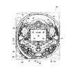
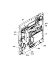
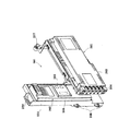
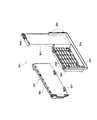
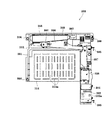
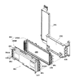
次に、裏パックユニット203の構成を説明する。裏パックユニット203は、樹脂成形された裏パック351と遊技球の払出機構部352とを一体化したものであり、裏パックユニット203の正面図を図20に示し、分解斜視図を図21に示す。   Next, the configuration of the back pack unit 203 will be described. The back pack unit 203 is formed by integrating a resin-molded back pack 351 and a game ball payout mechanism 352. FIG. 20 shows a front view of the back pack unit 203 and FIG. 21 shows an exploded perspective view thereof. Show.

裏パック351は例えばABS樹脂により一体成型されており、略平坦状のベース部353と、パチンコ機後方に突出し横長の略直方体形状をなす保護カバー部354とを有する。保護カバー部354は左右側面及び上面が閉鎖され且つ下面のみが開放された形状をなし、少なくとも可変表示装置ユニット35を囲むのに十分な大きさを有する(但し本実施の形態では、前述の音声ランプ制御装置262も合わせて囲む構成となっている)。保護カバー部354の背面には多数の通気孔354aが設けられている。この通気孔354aは各々が長孔状をなし、それぞれの通気孔354aが比較的近い位置で隣り合うよう設けられている。従って、隣り合う通気孔354a間にある樹脂部分を切断することにより、裏パック351の背面を容易に開口させることができる。つまり、通気孔354a間の樹脂部分を切断してその内部の表示制御装置45等を露出させることで、所定の検定等を容易に実施することができる。   The back pack 351 is integrally formed of, for example, ABS resin, and includes a substantially flat base portion 353 and a protective cover portion 354 that protrudes rearward of the pachinko machine and has a horizontally long substantially rectangular parallelepiped shape. The protective cover portion 354 has a shape in which the left and right side surfaces and the upper surface are closed and only the lower surface is opened, and has a size sufficient to surround at least the variable display device unit 35 (however, in the present embodiment, the above-mentioned audio The lamp control device 262 is also enclosed. A large number of ventilation holes 354 a are provided on the back surface of the protective cover portion 354. Each of the air holes 354a has a long hole shape, and the air holes 354a are adjacent to each other at a relatively close position. Therefore, the back surface of the back pack 351 can be easily opened by cutting the resin portion between the adjacent vent holes 354a. That is, a predetermined test or the like can be easily performed by cutting the resin portion between the vent holes 354a to expose the display control device 45 and the like inside.

また、ベース部353には、保護カバー部354を迂回するようにして払出機構部352が配設されている。すなわち、裏パック351の最上部には上方に開口したタンク355が設けられており、このタンク355には遊技ホールの島設備から供給される遊技球が逐次補給される。タンク355の下方には、例えば横方向2列(2条)の球通路を有し下流側に向けて緩やかに傾斜するタンクレール356が連結され、さらにタンクレール356の下流側には縦向きにケースレール357が連結されている。払出装置358はケースレール357の最下流部に設けられ、払出モータ等の所定の電気的構成により必要個数の遊技球の払出が適宜行われる。そして、払出装置358より払い出された遊技球は図21に示す払出通路359等を通じて前記上皿19に供給される。   In addition, a payout mechanism 352 is disposed on the base 353 so as to bypass the protective cover 354. That is, a tank 355 opened upward is provided at the uppermost portion of the back pack 351, and game balls supplied from the island facilities of the game hall are sequentially supplied to the tank 355. Below the tank 355, for example, a tank rail 356 that has two rows (two rows) of ball passages in the horizontal direction and that is gently inclined toward the downstream side is connected. Further, the tank rail 356 is arranged vertically on the downstream side of the tank rail 356. A case rail 357 is connected. The payout device 358 is provided at the most downstream portion of the case rail 357, and a required number of game balls are paid out appropriately according to a predetermined electrical configuration such as a payout motor. The game balls paid out from the payout device 358 are supplied to the upper plate 19 through the payout passage 359 and the like shown in FIG.

タンクレール356と、当該タンクレール356に振動を付加するためのバイブレータ360とが一体化となるようにユニット化されている。つまり、バイブレータ360が例えば2本のネジでタンクレール356に締結されて取り付けられるようになっている。さらに、バイブレータ360は、タンクレール356に面接触するのではなく、当該2本のネジの部分で接触するようになっており、バイブレータ360による振動がより効果的にタンクレール356に伝わるようになっている。従って、仮にタンクレール356付近で球詰まりが生じた際、バイブレータ360が駆動されることで球詰まりが解消されるようになっている。   The tank rail 356 and the vibrator 360 for applying vibration to the tank rail 356 are unitized so as to be integrated. That is, the vibrator 360 is fastened and attached to the tank rail 356 with, for example, two screws. Further, the vibrator 360 is not in surface contact with the tank rail 356 but is in contact with the two screw portions, so that the vibration by the vibrator 360 is more effectively transmitted to the tank rail 356. ing. Therefore, if a clogged ball occurs near the tank rail 356, the clogged ball is eliminated by driving the vibrator 360.

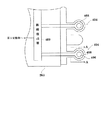
タンクレール356の構成について詳述すると、図22に示すように、タンクレール356は上方に開口した長尺樋状をなすレール本体361を有し、レール本体361の始端部には球面状の球受部362が設けられている。この球受部362により、タンク355より落下してきた遊技球が円滑にレール本体361内に取り込まれる。また、レール本体361には長手方向に延びる仕切壁363が設けられており、この仕切壁363により遊技球が二手に分流されるようになっている。仕切壁363により仕切られた2条の球通路は遊技球の直径よりも僅かに幅広となっている。仕切壁363により仕切られた各球通路の底面には、1筋又は2筋の突条364が設けられると共に、その突条364の側方に開口部365が設けられている。   The configuration of the tank rail 356 will be described in detail. As shown in FIG. 22, the tank rail 356 has a rail body 361 having a long bowl shape opened upward, and a spherical ball is formed at the start end of the rail body 361. A receiving part 362 is provided. By this ball receiving portion 362, the game ball dropped from the tank 355 is smoothly taken into the rail body 361. Further, the rail body 361 is provided with a partition wall 363 extending in the longitudinal direction, and the game balls are divided into two hands by the partition wall 363. The two ball passages partitioned by the partition wall 363 are slightly wider than the diameter of the game ball. One or two ridges 364 are provided on the bottom surface of each spherical passage partitioned by the partition wall 363, and an opening 365 is provided on the side of the ridge 364.

また、レール本体361には、その下流側半分程度の天井部分を覆うようにして整流板367が配設されている。この整流板367は、下流側になるほどタンクレール356内の球通路高さを制限するよう弓なりに反った形状をしており、さらにその下面には長手方向に延びる凸部368が形成されている。これにより、タンクレール356内を流れる各遊技球は最終的には上下に積み重なることなく下流側に流出する。従って、タンクレール356に多量の遊技球群が流れ込んできても、遊技球の噛み込みが防止され、タンクレール356内における球詰まりが解消されるようになっている。なお、レール本体361が黒色の導電性ポリカーボネート樹脂により成形されるのに対し、整流板367は透明のポリカーボネート樹脂により成形されている。整流板367は着脱可能に設けられており、当該整流板367を取り外すことによりタンクレール356内のメンテナンスが容易に実施できるようになっている。   In addition, a rectifying plate 367 is disposed on the rail body 361 so as to cover the ceiling portion of the downstream half. The rectifying plate 367 has a bowed shape so as to limit the height of the ball passage in the tank rail 356 toward the downstream side, and a convex portion 368 extending in the longitudinal direction is formed on the lower surface thereof. . Thereby, each game ball flowing in the tank rail 356 finally flows out downstream without being stacked up and down. Therefore, even if a large group of game balls flow into the tank rail 356, the game balls are prevented from being bitten and the ball clogging in the tank rail 356 is eliminated. The rail body 361 is formed of a black conductive polycarbonate resin, whereas the rectifying plate 367 is formed of a transparent polycarbonate resin. The rectifying plate 367 is detachably provided. By removing the rectifying plate 367, maintenance in the tank rail 356 can be easily performed.

図20,21の説明に戻り、払出機構部352には、払出制御装置311から払出装置358への払出指令の信号を中継する払出中継基板381が設置されると共に、外部より主電源を取り込むための電源スイッチ基板382が設置されている。電源スイッチ基板382には、電圧変換器を介して例えば交流24Vの主電源が供給され、電源スイッチ382aの切替操作により電源ON又は電源OFFとされるようになっている。   Returning to the description of FIGS. 20 and 21, the payout mechanism unit 352 is provided with a payout relay board 381 that relays a payout command signal from the payout control device 311 to the payout device 358, and takes in the main power from outside. The power switch board 382 is installed. The power switch board 382 is supplied with, for example, AC 24V main power via a voltage converter, and is turned on or off by switching the power switch 382a.

タンク355から払出通路359に至るまでの払出機構部352は何れも導電性を有する樹脂材料(例えば導電性ポリカーボネート樹脂)にて成形され、その一部にてアースされている。これにより、遊技球の帯電によるノイズの発生が抑制されるようになっている。   All of the dispensing mechanism 352 from the tank 355 to the dispensing passage 359 is formed of a conductive resin material (for example, conductive polycarbonate resin) and grounded at a part thereof. Thereby, generation | occurrence | production of the noise by charging of a game ball is suppressed.

また、裏パック351には、図20等の右端部に上下一対の支軸385が設けられており、この支軸385を図9等に示す支持孔部238に上方から挿通させることで、裏パックユニット203が内枠12に対して開閉可能に支持される。また、裏パック351には、左端部に締結具として上下一対のナイラッチ386が設けられると共に、上端部に係止孔387が設けられており、ナイラッチ386を図9等に示す被締結孔240にはめ込むと共に、係止孔387に図9等に示す固定具242を係止させることで、裏パックユニット203が内枠12に開閉不能に固定されるようになる。このとき、図9等に示す固定具241,243によっても裏パックユニット203が内枠12に固定される。なお、支持孔部238及び支軸385が前記図8の支軸部M6に、被締結孔240及びナイラッチ386が締結部M7に、固定具242及び係止孔387が係止部M8に、それぞれ相当する。また、固定具243が係止部M9に相当する。   Further, the back pack 351 is provided with a pair of upper and lower support shafts 385 at the right end portion in FIG. 20 and the like. By inserting the support shafts 385 into the support hole portion 238 shown in FIG. The pack unit 203 is supported so as to be openable and closable with respect to the inner frame 12. In addition, the back pack 351 is provided with a pair of upper and lower nai latches 386 as fasteners at the left end portion, and a locking hole 387 is provided at the upper end portion. The nai latch 386 is inserted into the tightened hole 240 shown in FIG. The back pack unit 203 is fixed to the inner frame 12 so that it cannot be opened and closed by engaging the fixing hole 387 shown in FIG. At this time, the back pack unit 203 is also fixed to the inner frame 12 by the fixtures 241 and 243 shown in FIG. The support hole 238 and the support shaft 385 are in the support shaft portion M6 in FIG. 8, the fastened hole 240 and the ny latch 386 are in the fastening portion M7, and the fixture 242 and the lock hole 387 are in the lock portion M8, respectively. Equivalent to. Further, the fixture 243 corresponds to the locking portion M9.

なお、図6,図20に示すように、内枠12の右上側には、内枠12が外枠11に対して開かれたことを検出する内枠開検出スイッチ388が設けられている。内枠12が開かれると、内枠開検出スイッチ388からホール内(パチンコ店内)用コンピュータへ出力されるようになっている。   As shown in FIGS. 6 and 20, an inner frame open detection switch 388 for detecting that the inner frame 12 is opened with respect to the outer frame 11 is provided on the upper right side of the inner frame 12. When the inner frame 12 is opened, it is outputted from the inner frame open detection switch 388 to the computer for the hall (in the pachinko parlor).

なお、図9に示すように、裏パックユニット203は、被締結孔240及びナイラッチ386と、固定具241,242とによって、内枠12の裏面に着脱自在に取り付けられている。このように固定具241,242も用いているので、タンク355に供給される遊技球の重みで裏パックユニット203が内枠12から外れてしまうことを防止している。   As shown in FIG. 9, the back pack unit 203 is detachably attached to the back surface of the inner frame 12 by a fastening hole 240, a ny latch 386, and fixtures 241 and 242. Since the fixtures 241 and 242 are also used in this way, the back pack unit 203 is prevented from being detached from the inner frame 12 due to the weight of the game balls supplied to the tank 355.

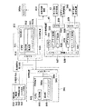
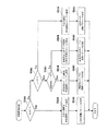
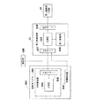
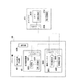
次に、本パチンコ機10の電気的構成について、図23を用いて説明する。図23は、本パチンコ機10の電気的構成を示したブロック図である。本パチンコ機10は、主制御装置261と、払出制御装置311と、発射制御装置312と、表示制御装置45と、電源装置313などを備えている。以下に、これらの装置を個別に詳細に説明する。   Next, the electrical configuration of the pachinko machine 10 will be described with reference to FIG. FIG. 23 is a block diagram showing an electrical configuration of the pachinko machine 10. The pachinko machine 10 includes a main control device 261, a payout control device 311, a launch control device 312, a display control device 45, a power supply device 313, and the like. In the following, these devices will be described in detail individually.

パチンコ機10の主制御装置261には、演算装置である1チップマイコンとしてのCPU501が搭載されている。CPU501には、該CPU501により実行される各種の制御プログラムや固定値データを記憶したROM502と、そのROM502内に記憶される制御プログラムの実行に際して各種のデータ等を一時的に記憶するためのメモリであるRAM503と、割込回路やタイマ回路、データ送受信回路などの各種回路が内蔵されている。   The main control device 261 of the pachinko machine 10 is equipped with a CPU 501 as a one-chip microcomputer that is an arithmetic device. The CPU 501 includes a ROM 502 that stores various control programs executed by the CPU 501 and fixed value data, and a memory that temporarily stores various data when the control program stored in the ROM 502 is executed. A RAM 503 and various circuits such as an interrupt circuit, a timer circuit, and a data transmission / reception circuit are incorporated.

RAM503は、パチンコ機10の電源のオフ後においても電源装置313からバックアップ電圧が供給されてデータが保持(バックアップ)できる構成となっており、RAM503には、各種のデータ等を一時的に記憶するためのメモリやエリアの他に、バックアップエリア503aが設けられている。   The RAM 503 has a configuration in which data can be retained (backed up) by being supplied with a backup voltage from the power supply device 313 even after the pachinko machine 10 is turned off. The RAM 503 temporarily stores various data and the like. In addition to the memory and area for this purpose, a backup area 503a is provided.

バックアップエリア503aは、停電などの発生により電源が切断された場合において、電源の再入時にパチンコ機10の状態を電源切断前の状態に復帰させるべく、電源切断時(停電発生時を含む。以下同様)のスタックポインタや、各レジスタ、I/O等の値を記憶しておくためのエリアである。バックアップエリア503aへの書き込みは、NMI割込み処理(図33参照)によって電源切断時に実行され、逆にバックアップエリア503aに書き込まれた各値の復帰は、電源入時(停電解消による電源入を含む。以下同様)の復電処理において実行される。なお、CPU501のNMI端子(ノンマスカブル割込端子)には、停電等の発生による電源断時に、後述する停電監視回路542から出力される停電信号S1が入力されるように構成されており、停電の発生により、図33の停電処理(NMI割込み処理)が即座に実行される。   In the backup area 503a, when the power is cut off due to a power failure or the like, the power of the pachinko machine 10 is restored to the state before the power is turned off when the power is turned on again. (Similar) is an area for storing stack pointers, values of registers, I / O, and the like. Writing to the backup area 503a is executed when the power is turned off by NMI interrupt processing (see FIG. 33). Conversely, returning of each value written to the backup area 503a includes turning on the power (including turning on the power due to power failure cancellation). The same applies to the following power recovery process. The N501 terminal (non-maskable interrupt terminal) of the CPU 501 is configured to receive a power failure signal S1 output from a power failure monitoring circuit 542, which will be described later, when a power failure occurs due to the occurrence of a power failure or the like. Due to the occurrence, the power failure process (NMI interrupt process) of FIG. 33 is immediately executed.

かかるROM502及びRAM503を内蔵したCPU501には、アドレスバス及びデータバスで構成されるバスライン504を介して入出力ポート505が接続されている。入出力ポート505には、後述するRAM消去スイッチ回路643、払出制御装置311、表示制御装置45や、その他図示しないスイッチ群などが接続されている。   An input / output port 505 is connected to the CPU 501 incorporating the ROM 502 and RAM 503 via a bus line 504 including an address bus and a data bus. The input / output port 505 is connected to a RAM erasing switch circuit 643, a payout control device 311, a display control device 45, and other switch groups (not shown).

また、払出制御装置311は、払出モータにより賞球や貸し球の払出制御を行うものである。演算装置であるCPU511は、そのCPU511により実行される制御プログラムや固定値データ等を記憶したROM512と、ワークメモリ等として使用されるRAM513とを備えている。   The payout control device 311 controls payout of prize balls and rental balls by a payout motor. The CPU 511 that is an arithmetic unit includes a ROM 512 that stores a control program executed by the CPU 511, fixed value data, and the like, and a RAM 513 that is used as a work memory or the like.

払出制御装置311のRAM513は、前述した主制御装置261のRAM503と同様に、パチンコ機10の電源のオフ後においても電源装置313からバックアップ電圧が供給されてデータが保持(バックアップ)できる構成となっており、RAM513には、各種のデータ等を一時的に記憶するためのメモリやエリアの他に、バックアップエリア513aが設けられている。   The RAM 513 of the payout control device 311 is configured to hold (backup) data by supplying a backup voltage from the power supply device 313 even after the pachinko machine 10 is turned off, like the RAM 503 of the main control device 261 described above. The RAM 513 is provided with a backup area 513a in addition to a memory and an area for temporarily storing various data.

バックアップエリア513aは、停電などの発生により電源が切断された場合において、電源の再入時にパチンコ機10の状態を電源切断前の状態に復帰させるべく、電源切断時のスタックポインタや、各レジスタ、I/O等の値を記憶しておくためのエリアである。このバックアップエリア513aへの書き込みは、NMI割込み処理(図33参照)によって電源切断時に実行され、逆にバックアップエリア513aに書き込まれた各値の復帰は、電源入時の復電処理において実行される。   The backup area 513a has a stack pointer, each register at the time of power off, each register, so that the power of the pachinko machine 10 is restored to the state before the power is turned off when the power is turned off. This is an area for storing values such as I / O. The writing to the backup area 513a is executed when the power is turned off by the NMI interrupt process (see FIG. 33), and the return of each value written to the backup area 513a is executed in the power recovery process when the power is turned on. .

かかるROM512及びRAM513を内蔵したCPU511には、アドレスバス及びデータバスで構成されるバスライン514を介して入出力ポート515が接続されている。入出力ポート515には、RAM消去スイッチ回路543、主制御装置261、発射制御装置312、払出モータ358aなどがそれぞれ接続されている。   An input / output port 515 is connected to the CPU 511 incorporating the ROM 512 and the RAM 513 through a bus line 514 including an address bus and a data bus. A RAM erase switch circuit 543, a main control device 261, a firing control device 312, a payout motor 358a, and the like are connected to the input / output port 515, respectively.

発射制御装置312は、発射モータ229による遊技球の発射を許可又は禁止するものであり、発射モータ229は、所定条件が整っている場合に駆動が許可される。具体的には、払出制御装置311から発射許可信号が出力されていること、遊技者が遊技球発射ハンドル18をタッチしていることをセンサ信号により検出していること、発射を停止させるための発射停止スイッチが操作されていないことを条件に、発射モータ229が駆動され、遊技球発射ハンドル18の操作量に応じた強度で遊技球が発射される。   The launch control device 312 permits or prohibits the launch of the game ball by the launch motor 229, and the launch motor 229 is permitted to drive when a predetermined condition is met. Specifically, it is detected by a sensor signal that a firing permission signal is output from the payout control device 311, that the player is touching the game ball launch handle 18, and the launch is stopped. On the condition that the firing stop switch is not operated, the firing motor 229 is driven, and the game ball is fired at an intensity corresponding to the operation amount of the game ball launch handle 18.

表示制御装置45は、第1図柄表示装置42における第1図柄の変動表示と、第2図柄表示装置41における第2図柄の変動表示とを制御するものである。この表示制御装置45は、CPU521と、ROM(プログラムROM)522と、ワークRAM523と、ビデオRAM524と、キャラクタROM525と、画像コントローラ526と、入力ポート527と、2つの出力ポート528,529と、バスライン530,531とを備えている。入力ポート527の入力には主制御装置261の出力が接続され、入力ポート527の出力には、CPU521、ROM522、ワークRAM523、画像コントローラ526が接続されると共にバスライン530を介して一方の出力ポート528が接続されている。出力ポート528の出力には第2図柄表示装置41(表示部43)や、音声ランプ制御装置262が接続されている。また、画像コントローラ526にはバスライン531を介して出力ポート529が接続されており、その出力ポート529の出力には液晶表示装置である第1図柄表示装置42が接続されている。   The display control device 45 controls the first symbol variation display on the first symbol display device 42 and the second symbol variation display on the second symbol display device 41. The display control device 45 includes a CPU 521, a ROM (program ROM) 522, a work RAM 523, a video RAM 524, a character ROM 525, an image controller 526, an input port 527, two output ports 528 and 529, and a bus. Lines 530 and 531 are provided. The output of the main controller 261 is connected to the input of the input port 527, and the CPU 521, ROM 522, work RAM 523, and image controller 526 are connected to the output of the input port 527 and one output port is connected via the bus line 530. 528 is connected. The output of the output port 528 is connected to the second symbol display device 41 (display unit 43) and the sound lamp control device 262. Further, an output port 529 is connected to the image controller 526 via a bus line 531, and a first symbol display device 42 which is a liquid crystal display device is connected to an output of the output port 529.

表示制御装置45のCPU521は、主制御装置261から送信される表示コマンドに基づいて第1図柄表示装置42及び第2図柄表示装置41の表示を制御する。ROM522は、そのCPU521により実行される各種の制御プログラムや固定値データを記憶するためのメモリであり、ワークRAM523は、CPU521による各種プログラムの実行時に使用されるワークデータやフラグを一時的に記憶するためのメモリである。   The CPU 521 of the display control device 45 controls the display of the first symbol display device 42 and the second symbol display device 41 based on the display command transmitted from the main control device 261. The ROM 522 is a memory for storing various control programs executed by the CPU 521 and fixed value data, and the work RAM 523 temporarily stores work data and flags used when the CPU 521 executes various programs. It is a memory for.

ビデオRAM524は、第1図柄表示装置42に表示される表示データを記憶するためのメモリであり、このビデオRAM524の内容を書き替えることにより、第1図柄表示装置42の表示内容が変更される。キャラクタROM525は、第1図柄表示装置42に表示される図柄などのキャラクタデータを記憶するためのメモリである。画像コントローラ526は、CPU521、ビデオRAM524、出力ポート529のそれぞれのタイミングを調整してデータの読み書きに介在すると共に、ビデオRAM524に記憶される表示データを、キャラクタROM525から所定のタイミングで読み出して第1図柄表示装置42に表示させるものである。   The video RAM 524 is a memory for storing display data displayed on the first symbol display device 42, and the display contents of the first symbol display device 42 are changed by rewriting the contents of the video RAM 524. The character ROM 525 is a memory for storing character data such as symbols displayed on the first symbol display device 42. The image controller 526 adjusts the timings of the CPU 521, the video RAM 524, and the output port 529 to intervene in reading and writing data, and also reads display data stored in the video RAM 524 from the character ROM 525 at a predetermined timing. It is displayed on the symbol display device 42.

また、電源装置313は、パチンコ機10の各部に電力を供給するための電源部541と、停電等による電源遮断を監視する停電監視回路542と、RAM消去スイッチ323に接続されてなるRAM消去スイッチ回路543とを備えている。電源部541は、図示しない電源経路を通じて、主制御装置261や払出制御装置311等に対して各々に必要な動作電源を供給する。その概要としては、電源部541は、外部より供給される交流24ボルト電源を取り込み、各種スイッチやモータ等を駆部するための+12V電源、ロジック用の+5V電源、RAMバックアップ用のバックアップ電源などを生成し、これら+12V電源、+5V電源及びバックアップ電源を主制御装置261や払出制御装置311等に対して供給する。なお、発射制御装置312に対しては払出制御装置311を介して動作電源(+12V電源、+5V電源等)が供給される。   The power supply unit 313 includes a power supply unit 541 for supplying power to each part of the pachinko machine 10, a power failure monitoring circuit 542 for monitoring power interruption due to a power failure, and a RAM erase switch connected to the RAM erase switch 323. A circuit 543. The power supply unit 541 supplies necessary operation power to the main control device 261, the payout control device 311 and the like through a power supply path (not shown). As an outline, the power supply unit 541 takes in an AC 24 volt power supply supplied from the outside, and supplies a + 12V power supply for driving various switches, motors, etc., a + 5V power supply for logic, a backup power supply for RAM backup, and the like. The + 12V power source, the + 5V power source, and the backup power source are supplied to the main control device 261, the payout control device 311 and the like. Note that operation power (+12 V power, +5 V power, etc.) is supplied to the launch control device 312 via the payout control device 311.

停電監視回路542は、停電等の発生による電源断時に、主制御装置261のCPU501及び払出制御装置311のCPU511の各NMl端子へ停電信号S1を出力するための回路である。停電監視回路542は、電源部541から出力される最大電圧である直流安定24ボルトの電圧を監視し、この電圧が22ボルト未満になった場合に停電(電源断)の発生と判断して、停電信号S1を主制御装置261及び払出制御装置311へ出力する。この停電信号S1の出力によって、主制御装置261及び払出制御装置311は、停電の発生を認識し、停電時処理(図33のNMI割込み処理)を実行する。   The power failure monitoring circuit 542 is a circuit for outputting a power failure signal S1 to each NMl terminal of the CPU 501 of the main control device 261 and the CPU 511 of the payout control device 311 when the power is cut off due to the occurrence of a power failure or the like. The power failure monitoring circuit 542 monitors the DC stable voltage of 24 volts, which is the maximum voltage output from the power supply unit 541, and determines that a power failure (power failure) has occurred when this voltage is less than 22 volts. The power failure signal S1 is output to the main controller 261 and the payout controller 311. Based on the output of the power failure signal S1, the main control device 261 and the payout control device 311 recognize the occurrence of the power failure and execute the power failure processing (NMI interrupt processing in FIG. 33).

なお、電源部541は、直流安定24ボルトの電圧が22ボルト未満になった後においても、かかる停電時処理の実行に充分な時間の間、制御系の駆動電圧である5ボルトの出力を正常値に維持するように構成されている。よって、主制御装置261及び払出制御装置311は、停電時処理を正常に実行し完了することができる。   The power supply unit 541 normally outputs an output of 5 volts, which is a drive voltage of the control system, for a time sufficient to execute the process at the time of a power failure even after the DC stable voltage of 24 volts becomes less than 22 volts. Configured to maintain the value. Therefore, the main control device 261 and the payout control device 311 can normally execute and complete the power failure process.

RAM消去スイッチ回路543は、RAM消去スイッチ323のスイッチ信号を取り込み、そのスイッチ323の状態に応じて主制御装置261のRAM503及び払出制御装置311のRAM513のバックアップデータをクリアするための回路である。RAM消去スイッチ323が押下された際、RAM消去スイッチ回路543は、RAM消去信号S2を主制御装置261及び払出制御装置311に出力する。RAM消去スイッチ323が押下された状態でパチンコ機10の電源が投入されると(停電解消による電源入を含む)、主制御装置261及び払出制御装置311においてそれぞれのRAM503,613のデータがクリアされる。   The RAM erase switch circuit 543 is a circuit for taking in the switch signal of the RAM erase switch 323 and clearing backup data in the RAM 503 of the main controller 261 and the RAM 513 of the payout controller 311 in accordance with the state of the switch 323. When the RAM erase switch 323 is pressed, the RAM erase switch circuit 543 outputs a RAM erase signal S2 to the main controller 261 and the payout controller 311. When the power of the pachinko machine 10 is turned on with the RAM erase switch 323 pressed (including power-on due to power failure cancellation), the data in the respective RAMs 503 and 613 are cleared in the main controller 261 and the payout controller 311. The

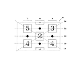
ところで、第1図柄表示装置(液晶表示装置)42には、図24に示すように、左・中・右の3つの図柄列L,M,Rが設定されており、図柄列L,M,R毎に上図柄、中図柄、下図柄の3個ずつの図柄(第1図柄:例えば特別図柄)が変動表示される。本実施の形態では、一連の図柄は、「0」〜「9」の数字を各々付した主図柄と、菱形状の絵図柄からなる副図柄とにより構成されており、数字の昇順又は降順に主図柄が表示されると共に各主図柄の間に副図柄が配されて一連の図柄列L,M,Rが構成されている。そして、周期性を持って主図柄と副図柄が上から下へと変動表示されるようになっている。   By the way, in the first symbol display device (liquid crystal display device) 42, as shown in FIG. 24, three symbol rows L, M, and R of left, middle, and right are set. For each R, three symbols of the upper symbol, the middle symbol, and the lower symbol (the first symbol: for example, a special symbol) are variably displayed. In the present embodiment, the series of symbols is composed of a main symbol with numbers “0” to “9” and a sub-pattern consisting of rhombus-shaped symbols, in ascending or descending order of the numbers. A main symbol is displayed, and a sub-symbol is arranged between the main symbols to form a series of symbol rows L, M, and R. The main symbol and the sub symbol are variably displayed from top to bottom with periodicity.

かかる場合、左図柄列Lにおいては、上記一連の図柄が降順(すなわち、主図柄の番号が減る順)に表示され、中図柄列M及び右図柄列Rにおいては、同じく上記一連の図柄が昇順(すなわち、主図柄の番号が増える順)に表示される。そして、左図柄列L→右図柄列R→中図柄列Mの順に変動表示が停止し、その停止時に第1図柄表示襲置42上の5つの有効ライン、すなわち上ラインL1、中ラインL2、下ラインL3、右上がりラインL4、左上がりラインL5の何れかで主図柄が大当たり図柄の組合せ(本実施の形態では、同一の主図柄の組合せ)で揃えば大当たりとして特別遊技動画が表示されるようになっている。   In this case, in the left symbol row L, the series of symbols is displayed in descending order (that is, in the order of decreasing the number of the main symbol), and in the middle symbol row M and the right symbol row R, the series of symbols is also in ascending order. (That is, in order of increasing main symbol numbers). Then, the variable display stops in the order of the left symbol row L → the right symbol row R → the middle symbol row M, and at the time of the stop, five effective lines on the first symbol display raid 42, that is, the upper line L1, the middle line L2, A special game video is displayed as a jackpot if the main symbol is aligned with a jackpot symbol combination (in this embodiment, the same main symbol combination) in any of the lower line L3, the rightward rising line L4, and the leftward rising line L5. It is like that.

次に、上記の如く構成されたパチンコ機10の動作について説明する。   Next, the operation of the pachinko machine 10 configured as described above will be described.

本実施の形態では、主制御装置261内のCPU501は、遊技に際し各種カウンタ情報を用いて第1図柄表示装置42の抽選(大当たり抽選)や図柄表示の設定などを行うこととしており、具体的には、図25に示すように、第1図柄表示装置42の大当たりの抽選に使用する大当たり乱数カウンタC1と、第1図柄表示装置42の大当たり図柄の選択に使用する大当たり図柄カウンタC2と、第1図柄表示装置42が外れ変動する際のリーチ抽選に使用するリーチ乱数カウンタC3と、大当たり乱数カウンタC1の初期値設定に使用する乱数初期値カウンタCINIと、第1図柄表示装置42の変動パターン選択に使用する変動種別カウンタCS1,CS2と、左列、中列及び右列の各外れ図柄の設定に使用する左・中・右の各外れ図柄カウンタCL,CM,CRとを用いることとしている。上述した各カウンタは、CPU501で実行されるプログラムにより構成されている。   In the present embodiment, the CPU 501 in the main control device 261 performs lottery (big hit lottery) of the first symbol display device 42, setting of symbol display, and the like using various counter information in the game. Specifically, 25, the jackpot random number counter C1 used for the jackpot lottery of the first symbol display device 42, the jackpot symbol counter C2 used for the selection of the jackpot symbol of the first symbol display device 42, and the first Reach random number counter C3 used for reach lottery when the symbol display device 42 fluctuates and changes, random number initial value counter CINI used for initial value setting of the jackpot random number counter C1, and variation pattern selection of the first symbol display device 42 Fluctuation type counters CS1 and CS2 to be used, and left, middle and right outliers used for setting left out, middle and right outliers Counter CL, CM, has been with the use of the CR. Each counter described above is constituted by a program executed by the CPU 501.

このうち、カウンタC1〜C3,CINI,CS1,CS2は、その更新の都度、前回値に「1」が加算され(以下、「更新」という)、最大値に達した後「0」に戻るループカウンタとなっている。また、外れ図柄カウンタCL,CM,CRは、CPU501内のRレジスタ(リフレッシュレジスタ)を用いてレジスタ値が加算され、結果的に数値がランダムに変化する構成となっている。各カウンタは定期的に更新され、その更新値がRAM503の所定領域に設定されたカウンタ用バッファに適宜格納される。また、RAM503には、1つの実行エリアと4つの保留エリア(保留第1〜第4エリア)とからなる保留球格納エリアが設けられており、これらの各エリアには、第1の始動口33への遊技球の入賞履歴に合わせて、大当たり乱数カウンタC1、大当たり図柄カウンタC2及びリーチ乱数カウンタC3の各値が時系列的に格納されるようになっている。   Among these, the counters C1 to C3, CINI, CS1 and CS2 each have a loop in which “1” is added to the previous value (hereinafter referred to as “update”) and returns to “0” after reaching the maximum value. It is a counter. Further, the out symbol counters CL, CM, CR are configured such that register values are added using an R register (refresh register) in the CPU 501, and as a result, numerical values change randomly. Each counter is periodically updated, and the updated value is appropriately stored in a counter buffer set in a predetermined area of the RAM 503. The RAM 503 is provided with a holding ball storage area including one execution area and four holding areas (holding first to fourth areas). In each of these areas, the first start port 33 is provided. Each value of the jackpot random number counter C1, the jackpot symbol counter C2 and the reach random number counter C3 is stored in time series in accordance with the winning history of the game balls.

各カウンタについて詳しくは、大当たり乱数カウンタC1は、例えば「0」〜「676」の範囲内で順に「1」ずつ加算され、最大値(つまり「676」)に達した後「0」に戻る構成となっている。特に大当たり乱数カウンタC1が1周した場合、その時点の乱数初期値カウンタCINIの値が当該大当たり乱数カウンタC1の初期値として読み込まれる。なお、乱数初期値カウンタCINIは、大当たり乱数カウンタC1と同様のループカウンタであり(値=0〜676)、タイマ割込み毎に1回更新されると共に通常処理の残余時間内で綴り返し更新される。大当たり乱数カウンタC1は定期的に(本実施の形態ではタイマ割込み毎に1回)更新され、遊技球が第1の始動口33に入賞したタイミングでRAM503の保留球格納エリアに格納される。大当たりとなる乱数の値の数は、低確率時と高確率時とで2種類設定されており、低確率時に大当たりとなる乱数の値の個数は2で、その値は「337,673」であり、高確率時に大当たりとなる乱数の値の個数は10で、その値は 「67,131,199,289,337,401,463,523,601,661」である。なお、高確率時とは、予め定められた確率変動図柄によって大当たりになり付加価値としてその後の大当たり確率がアップした状態、いわゆる「確変」の時をいい、通常時(低確率時)とはそのような確変状態でない時をいう。   For details of each counter, the jackpot random number counter C1 is, for example, sequentially incremented by “1” within a range of “0” to “676” and returns to “0” after reaching the maximum value (that is, “676”). It has become. In particular, when the jackpot random number counter C1 makes one round, the value of the random number initial value counter CINI at that time is read as the initial value of the jackpot random number counter C1. The random number initial value counter CINI is a loop counter similar to the big hit random number counter C1 (value = 0 to 676), and is updated once for each timer interruption and updated repeatedly within the remaining time of normal processing. . The jackpot random number counter C1 is updated periodically (once every timer interruption in this embodiment) and stored in the reserved ball storage area of the RAM 503 at the timing when the game ball wins the first start port 33. The number of random number values that are jackpots is set at low probability and high probability, and the number of random number values that are jackpots at low probability is 2, and the value is “337,673”. There are 10 random numbers that are big hits at high probability, and the values are “67, 131, 199, 289, 337, 401, 463, 523, 601, 661”. High probability means a state where the jackpot is won by a predetermined probability variation pattern and the subsequent jackpot probability is increased as added value, so-called “probability”, and normal time (low probability) is This is the time when it is not in a probable state.

大当たり図柄カウンタC2は、大当たりの際、第1図柄表示装置42の変動停止時の図柄を決定するものであり、本実施の形態では、第1図柄表示装置42において有効ラインが5ラインであり、特定図柄(主図柄)が10通り設定されていることから、50個(0〜49)のカウンタ値が用意されている。すなわち、大当たり図柄カウンタC2は、0〜49の範囲内で順に1ずつ加算され、最大値(つまり49)に達した後0に戻る構成となっている。大当たり図柄カウンタC2は定期的に(本実施の形態ではタイマ割込み毎に1回)更新され、遊技球が第1の始動口33に入賞したタイミングでRAM503の保留球格納エリアに格納される。   The jackpot symbol counter C2 determines a symbol at the time of fluctuation stop of the first symbol display device 42 in the case of a jackpot. In the present embodiment, the first symbol display device 42 has five effective lines, Since ten specific symbols (main symbols) are set, 50 counter values (0 to 49) are prepared. That is, the jackpot symbol counter C2 is incremented by 1 within a range of 0 to 49, and reaches a maximum value (that is, 49) and then returns to 0. The jackpot symbol counter C2 is updated periodically (once every timer interruption in this embodiment), and stored in the reserved ball storage area of the RAM 503 at the timing when the game ball wins the first start port 33.

また、リーチ乱数カウンタC3は、例えば0〜238の範囲内で順に1ずつ加算され、最大値(つまり238)に達した後0に戻る構成となっている。本実施の形態では、リーチ乱数カウンタC3によって、リーチ発生した後最終停止図柄がリーチ図柄の前後に1つだけずれて停止する「前後外れリーチ」と、同じくリーチ発生した後最終停止図柄がリーチ図柄の前後以外で停止する「前後外れ以外リーチ」と、リーチ発生しない「完全外れ」とを抽選することとしており、例えば、C3=0,1が前後外れリーチに該当し、C3=2〜21が前後外れ以外リーチに該当し、C3=22〜238が完全外れに該当する。なお、リーチの抽通は、第1図柄表示装置42の抽選確率の状態や変動開始時の作動保留球数等に応じて各々個別に設定されるものであっても良い。リーチ乱数カウンタC3は定期的に(本実施の形態ではタイマ割込み毎に1回)更新され、遊技球が第1の始動口33に入賞したタイミングでRAM503の保留球格納エリアに格納される。   Further, the reach random number counter C3 is configured to increment one by one within a range of 0 to 238, for example, and returns to 0 after reaching the maximum value (that is, 238). In the present embodiment, the reach random number counter C3 causes the last stop symbol to stop after the reach has occurred by shifting the last stop symbol by one before and after the reach symbol, and the last stop symbol after the reach has also occurred. “Reach other than front / rear out” and stop “completely out” where no reach occurs, for example, C3 = 0, 1 corresponds to front / rear reach, and C3 = 2-21 It corresponds to the reach other than the front and rear deviation, and C3 = 22 to 238 corresponds to the complete deviation. Note that the reach drawing may be set individually according to the state of the lottery probability of the first symbol display device 42, the number of suspended balls at the start of change, and the like. The reach random number counter C3 is updated periodically (once every timer interruption in this embodiment) and stored in the reserved ball storage area of the RAM 503 at the timing when the game ball wins the first start port 33.

また、2つの変動種別カウンタCS1,CS2のうち、一方の変動種別カウンタCS1は、例えば0〜198の範囲内で順に1ずつ加算され、最大値(つまり198)に達した後0に戻る構成となっており、他方の変動種別カウンタCS2は、例えば0〜240の範囲内で順に1ずつ加算され、最大値(つまり240)に達した後0に戻る構成となっている。以下の説明では、CS1を「第1変動種別カウンタ」、CS2を「第2変動種別カウンタ」ともいう。第1変動種別カウンタCS1によって、いわゆるノーマルリーチ、スーパーリーチ、プレミアムリーチ等、第1図柄のリーチ種別やその他大まかな図柄変動態様が決定され、第2変動種別カウンタCS2によって、リーチ発生後に最終停止図柄(本実施の形態では中図柄)が停止するまでの経過時間(言い換えれば、変動図柄数)などより細かな図柄変動態様が決定される。従って、これらの変動種別カウンタCS1,CS2を組み合わせることで、変動パターンの多種多様化を容易に実現できる。また、第1変動種別カウンタCS1だけで図柄変動態様を決定したり、第1変動種別カウンタCS1と停止図柄との組み合わせで同じく図柄変動態様を決定したりすることも可能である。   Further, one of the two variation type counters CS1 and CS2 is incremented by one within a range of 0 to 198, for example, and reaches a maximum value (that is, 198) and then returns to 0. For example, the other variation type counter CS2 is incremented one by one within a range of 0 to 240, for example, and reaches the maximum value (that is, 240) and then returns to 0. In the following description, CS1 is also referred to as “first variation type counter”, and CS2 is also referred to as “second variation type counter”. The first variation type counter CS1 determines the reach type of the first symbol such as so-called normal reach, super reach, premium reach, and other rough symbol variation modes, and the second variation type counter CS2 determines the final stop symbol ( In the present embodiment, a more detailed symbol variation mode such as an elapsed time (in other words, the number of variation symbols) until the middle symbol) stops is determined. Therefore, a variety of variation patterns can be easily realized by combining these variation type counters CS1 and CS2. It is also possible to determine the symbol variation mode only by the first variation type counter CS1, or to determine the symbol variation mode similarly by combining the first variation type counter CS1 and the stop symbol.

変動種別カウンタCS1,CS2は、後述する通常処理が1回実行される毎に1回更新され、当該通常処理内の残余時間内でも繰り返し更新される。そして、第1図柄表示装置42による第1図柄の変動開始時における変動パターン決定に際してCS1,CS2のバッファ値が取得される。   The variation type counters CS1 and CS2 are updated once every time a normal process to be described later is executed once, and are repeatedly updated even within the remaining time in the normal process. Then, the buffer values of CS1 and CS2 are acquired when the first symbol display device 42 determines the variation pattern at the start of variation of the first symbol.

左・中・右の各外れ図柄カウンタCL,CM,CRは、第1図柄表示装置42の大当たり抽選が外れとなった時に左列第1図柄、中列第1図柄、右列第1図柄の停止図柄(外れ図柄)を決定するためのものであり、各列では主図柄及び副図柄の合わせて20の第1図柄の何れかが表示されることから、各々に20個(0〜19)のカウンタ値が用意されている。外れ図柄カウンタCLにより左図柄列の上・中・下段の各図柄が決定され、外れ図柄カウンタCMにより中図柄列の上・中・下段の各図柄が決定され、外れ図柄カウンタCRにより右図柄列の上・中・下段の各図柄が決定される。   The left, middle, and right out symbol counters CL, CM, and CR indicate that the first symbol in the left column, the first symbol in the middle column, and the first symbol in the right column when the jackpot lottery of the first symbol display device 42 is lost. This is for determining the stop symbol (disconnected symbol). In each column, any one of the 20 first symbols including the main symbol and the sub symbol is displayed, so 20 (0 to 19) each. Counter values are provided. The left, upper, middle, and lower symbols are determined by the out symbol counter CL, the upper, middle, and lower symbols are determined by the out symbol counter CM, and the right symbol column is determined by the out symbol counter CR. The top, middle and bottom symbols are determined.

本実施の形態では、CPU501に内蔵のRレジスタの数値を用いることにより各カウンタCL,CM,CRの値をランダムに更新する構成としている。すなわち、各外れ図柄カウンタCL,CM,CRの更新時には、前回値にRレジスタの下位3ビットの値が加算され、その加算給果が最大値を超えた場合に20減算されて今回値が決定される。各外れ図柄カウンタCL,CM,CRは更新時期が重ならないようにして通常処理内で更新され、それら外れ図柄カウンタCL,CM,CRの組み合わせが、RAM503の前後外れリーチ図柄バッファ、前後外れ以外リーチ図柄バッファ及び完全外れ図柄バッファの何れかに格納される。そして、第1図柄の変動開始時における変動パターン決定に際し、リーチ乱数カウンタC3の値に応じて前後外れリーチ図柄バッファ、前後外れ以外リーチ図柄バッファ及び完全外れ図柄バッファの何れかのバッファ値が取得される。   In the present embodiment, the values of the counters CL, CM, and CR are randomly updated by using the value of the R register built in the CPU 501. That is, when each outlier symbol counter CL, CM, CR is updated, the lower 3 bits of the R register are added to the previous value, and when the added result exceeds the maximum value, 20 is subtracted to determine the current value. Is done. Each outlier symbol counter CL, CM, CR is updated within the normal process so that the update times do not overlap, and the combination of these outlier symbol counters CL, CM, CR is the reach of the RAM 503 front / rear reach symbol buffer, reach other than front / rear out It is stored in either the symbol buffer or the completely off symbol buffer. Then, when determining the variation pattern at the time of starting the variation of the first symbol, the buffer value of any one of the front and rear outreach symbol buffer, the reach symbol buffer other than front and rear outlier, and the completely out symbol symbol buffer is acquired according to the value of the reach random number counter C3. The

各カウンタの大きさや範囲は一例にすぎず任意に変更できる。但し、大当たり乱数カウンタC1、リーチ乱数カウンタC3、変動種別カウンタCS1,CS2の大きさは何れも異なる素数とし、いかなる場合にも同期しない数値としておくのが望ましい。   The size and range of each counter is only an example and can be arbitrarily changed. However, it is desirable that the big hit random number counter C1, the reach random number counter C3, and the variation type counters CS1 and CS2 are all different prime numbers and are not synchronized in any case.

また図示は省略するが、第2図柄表示装置41の抽選には第2図柄乱数カウンタC4が用いられる。第2図柄乱数カウンタC4は、例えば0〜250の範囲内で順に1ずつ加算され、最大値(つまり250)に達した後0に戻るループカウンタとして構成されている。第2図柄乱数カウンタC4は定期的に(本実施の形態ではタイマ割込み毎に1回)更新され、遊技球が左右何れかの第2の始動口34を通過した時に取得される。当選することとなる乱数の値の数は149あり、その範囲は「5〜153」である。   Although not shown, the second symbol random number counter C4 is used for the lottery of the second symbol display device 41. The second symbol random number counter C4 is configured as a loop counter that is incremented one by one within a range of 0 to 250, for example, and returns to 0 after reaching the maximum value (that is, 250). The second symbol random number counter C4 is periodically updated (once every timer interruption in the present embodiment), and is acquired when the game ball passes through the second start port 34 on either the left or right side. The number of random number values to be won is 149, and the range is “5 to 153”.

次いで、主制御装置261内のCPU501により実行される各制御処理を図26〜図37のフローチャートを参照しながら説明する。かかるCPU501の処理としては大別して、電源投入に伴い起動されるメイン処理と、定期的に(本実施の形態では2msec周期で)起動されるタイマ割込み処理と、NMl端子(ノンマスカブル端子)への停電信号の入力により起動されるNMI割込み処理とがあり、説明の便宜上ここでは、先ずタイマ割込み処理とNMI割込み処理とを説明し、その後でメイン処理を税明する。   Next, each control process executed by the CPU 501 in the main controller 261 will be described with reference to the flowcharts of FIGS. The processing of the CPU 501 is broadly divided into a main processing that is started when the power is turned on, a timer interrupt processing that is started periodically (in this embodiment at a cycle of 2 msec), and a power failure to the NMl terminal (non-maskable terminal). There is an NMI interrupt process activated by signal input. For convenience of explanation, the timer interrupt process and the NMI interrupt process will be described first, and then the main process will be taxed.

図31は、タイマ割込み処理を示すフローチャートであり、本処理は主制御装置261のCPU501により例えば2msec毎に実行される。   FIG. 31 is a flowchart showing the timer interrupt process. This process is executed by the CPU 501 of the main controller 261 every 2 msec, for example.

図31において、先ずステップS601では、各種入賞スイッチの読み込み処理を実行する。すなわち、主制御装置261に接続されている各種スイッチ(但し、RAM消去スイッチ323を除く)の状態を読み込むと共に、当該スイッチの状態を判定して検出情報(入賞検知情報)を保存する。   In FIG. 31, first, in step S601, reading processing of various winning switches is executed. That is, the state of various switches (except for the RAM erase switch 323) connected to the main controller 261 is read, and the state of the switch is determined and the detection information (winning detection information) is stored.

その後、ステップS602では、乱数初期値カウンタCINIの更新を実行する。具体的には、乱数初期値カウンタCINIを1インクリメントすると共に、そのカウンタ値が最大値(本実施の形態では676)に達した際0にクリアする。そして、乱数初期値カウンタCINIの更新値を、RAM503の該当するバッファ領域に格納する。また、続くステップS603では、大当たり乱数カウンタC1、大当たり図柄カウンタC2及びリーチ乱数カウンタC3の更新を実行する。具体的には、大当たり乱数カウンタC1、大当たり図柄カウンタC2及びリーチ乱数カウンタC3をそれぞれ1インクリメントすると共に、それらのカウンタ値が最大値(本実施の形態ではそれぞれ、676,49,238)に達した際それぞれ0にクリアする。そして、各カウンタC1〜C3の更新値を、RAM503の該当するバッファ領域に格納する。   Thereafter, in step S602, the random number initial value counter CINI is updated. Specifically, the random number initial value counter CINI is incremented by 1 and cleared to 0 when the counter value reaches the maximum value (676 in the present embodiment). Then, the update value of the random number initial value counter CINI is stored in the corresponding buffer area of the RAM 503. In subsequent step S603, the big hit random number counter C1, the big hit symbol counter C2, and the reach random number counter C3 are updated. Specifically, the jackpot random number counter C1, the jackpot symbol counter C2, and the reach random number counter C3 are each incremented by 1 and their counter values reach the maximum values (in this embodiment, 676, 49, and 238, respectively). Each time it is cleared to 0. Then, the updated values of the counters C1 to C3 are stored in the corresponding buffer area of the RAM 503.

その後、ステップS604では、第1の始動口33への入賞に伴う始動入賞処理を実行する。この始動入賞処理を図32のフローチャートにより説明すると、ステップS701では、遊技球が第1の始動口33に入賞したか否かを作動口スイッチ224の検出情報により判別する。遊技球が第1の始動口33に入賞したと判別されると、続くステップS702では、第1図柄表示装置42の作動保留球数Nが上限値(本実施の形態では4)未満であるか否かを判別する。第1の始動口33への入賞があり、且つ作動保留球数N<4であることを条件にステップS703に進み、作動保留球数Nを1インクリメントする。   Thereafter, in step S604, a start winning process associated with winning in the first start port 33 is executed. This start winning process will be described with reference to the flowchart of FIG. 32. In step S701, whether or not the game ball has won the first start opening 33 is determined based on the detection information of the operation opening switch 224. If it is determined that the game ball has won the first start opening 33, in the subsequent step S702, is the number N of active suspension balls of the first symbol display device 42 less than the upper limit value (4 in the present embodiment)? Determine whether or not. The process proceeds to step S703 on the condition that there is a winning at the first start port 33 and the number N of activated balls is <4, and the number N of activated balls is incremented by one.

また、続くステップS704では、第1図柄の当落に関わる乱数を取得する。具体的には、前記ステップS603で更新した大当たり乱数カウンタC1、大当たり図柄カウンタC2及びリーチ乱数カウンタC3の各値を、RAM503の保留球格納エリアの空き記憶エリアのうち最初のエリアに格納する。このように始動入賞処理をした後、CPU501は本タイマ割込処理を一旦終了する。   In subsequent step S704, a random number related to the winning of the first symbol is acquired. Specifically, the values of the jackpot random number counter C1, the jackpot symbol counter C2 and the reach random number counter C3 updated in step S603 are stored in the first area of the free storage area of the reserved ball storage area of the RAM 503. After performing the start winning process in this way, the CPU 501 once ends the timer interrupt process.

図33は、NMI割込み処理を示すフローチャートであり、本処理は、主制御装置261のCPU501により停電の発生等によるパチンコ機10の電源断時に実行される。このNMI割込みにより、電源断時の主制御装置261の状態がRAM503のバックアップエリア503aに記憶される。   FIG. 33 is a flowchart showing the NMI interrupt process, and this process is executed by the CPU 501 of the main controller 261 when the power of the pachinko machine 10 is cut off due to the occurrence of a power failure or the like. By this NMI interruption, the state of the main controller 261 at the time of power-off is stored in the backup area 503a of the RAM 503.

すなわち、停電の発生等によりパチンコ機10の電源が遮断されると、停電信号S1が停電監視回路542から主制御装置261内のCPU501のNMI端子に出力される。すると、CPU501は実行中の制御を中断して図33のNMI割込み処理を開始する。図33のNMI割込み処理は、主制御装置261のROM502に記憶されている。停電信号S1が出力された後所定時間は、主制御装置261の処理が実行可能となるように電源部541から電源供給がなされており、この所定時間内にNMI割込み処理が実行される。   That is, when the power of the pachinko machine 10 is cut off due to the occurrence of a power failure or the like, the power failure signal S1 is output from the power failure monitoring circuit 542 to the NMI terminal of the CPU 501 in the main controller 261. Then, the CPU 501 interrupts the control being executed and starts the NMI interrupt process of FIG. 33 is stored in the ROM 502 of the main controller 261. For a predetermined time after the power failure signal S1 is output, power is supplied from the power supply unit 541 so that the processing of the main controller 261 can be executed, and the NMI interrupt processing is executed within the predetermined time.

図33のNMI割込み処理において、先ずステップS801では、使用レジスタをRAM503のバックアップエリア503aに退避し、続くステップS802では、スタックポインタの値を同バックアップエリア503aに記憶する。さらに、ステップS803では、電源断の発生情報をバックアップエリア503aに設定し、ステップS804では、電源が速断されたことを示す電源断通知コマンドを他の制御装置に対して送信する。   In the NMI interrupt processing of FIG. 33, first, in step S801, the used registers are saved in the backup area 503a of the RAM 503, and in the subsequent step S802, the value of the stack pointer is stored in the backup area 503a. Further, in step S803, the information on the occurrence of power interruption is set in the backup area 503a, and in step S804, a power interruption notification command indicating that the power has been rapidly interrupted is transmitted to another control device.

ステップS805ではRAM判定値を算出し、バックアップエリア503aに保存する。RAM判定値は、例えば、RAM503の作業領域アドレスにおけるチェックサム値である。ステップS806では、RAMアクセスを禁止する。その後は、電源が完全に遮断して処理が実行できなくなるのに備え、無限ループに入る。   In step S805, a RAM determination value is calculated and stored in the backup area 503a. The RAM determination value is, for example, a checksum value at the work area address of the RAM 503. In step S806, RAM access is prohibited. Thereafter, an infinite loop is entered in preparation for the power supply being completely shut down and the processing being impossible.

なお、上記のNMI割込み処理は払出制御装置311でも同様に実行され、かかるNMI割込みにより、停電の発生等による電源断時の払出制御装置311の状態がRAM513のバックアップエリア513aに記憶される。停電信号S1が出力された後所定時間は、払出制御装置311の処理が実行可能となるように電源部541から電源供給がなされるのも同様である。すなわち、停電の発生等によりパチンコ機10の電源が遮断されると、停電信号S1が停電監視回路542から払出制御装置311内のCPU511のNMl端子に出力され、CPU511は実行中の制御を中断して図33のNMI割込み処理を開始する。その内容は図33で説明した通りである(但し、この払出制御装置311のNMI割込み処理ではステップS804の電源断通知コマンドの送信はない)。   The NMI interrupt process is also executed in the payout control device 311 in the same manner, and the state of the payout control device 311 when the power is cut off due to the occurrence of a power failure or the like is stored in the backup area 513a of the RAM 513. Similarly, the power is supplied from the power supply unit 541 so that the processing of the payout control device 311 can be executed for a predetermined time after the power failure signal S1 is output. That is, when the power of the pachinko machine 10 is cut off due to the occurrence of a power failure or the like, the power failure signal S1 is output from the power failure monitoring circuit 542 to the NMl terminal of the CPU 511 in the payout control device 311 and the CPU 511 interrupts the control being executed. The NMI interrupt process of FIG. 33 is started. The contents are as described with reference to FIG. 33 (however, the NMI interrupt processing of the payout control device 311 does not transmit the power-off notification command in step S804).

次に、メイン処理について説明する。   Next, the main process will be described.

図26は、主制御装置261内のCPU501により実行されるメイン処理の一例を示すフローチャートであり、このメイン処理は電源投入時のリセットに伴い起動される。   FIG. 26 is a flowchart showing an example of a main process executed by the CPU 501 in the main control device 261. This main process is started upon reset when power is turned on.

先ず、ステップS101では、電源投入に伴う初期設定処理を実行する。具体的には、スタックポインタに予め決められた所定値を設定すると共に、サブ側の制御装置(音声ランプ制御装置262、払出制御装置311等)が動作可能な状態になるのを待つために例えば1秒程度、ウエイト処理を実行する。また、ステップS102では、払出制御装置311に対して払出許可コマンドを送信し、続くステップS103では、RAMアクセスを許可する。   First, in step S101, an initial setting process associated with power-on is executed. Specifically, in order to set a predetermined value in the stack pointer and wait for the sub-side control devices (such as the sound lamp control device 262 and the payout control device 311) to become operable, for example, Wait processing is performed for about 1 second. In step S102, a payout permission command is transmitted to the payout control device 311. In subsequent step S103, RAM access is permitted.

その後、CPU501内のRAM503に関してデータバックアップの処理を実行する。つまり、ステップS104では、電源装置313に設けたRAM消去スイッチ323が押下(ON)されているか否かを判別し、続くステップS105では、RAM503のバックアップエリア503aに電源断の発生情報が設定されているか否かを判別する。また、ステップS106ではRAM判定値を算出し、続くステップS107では、そのRAM判定値が電源断時に保存したRAM判定値と一致するか否か、すなわちバックアップの有効性を判別する。RAM判定値は、例えばRAM503の作業領域アドレスにおけるチェックサム値である。なお、RAM503の所定のエリアに書き込まれたキーワードが正しく保存されているか否かによりバックアップの有効性を判断することも可能である。   Thereafter, data backup processing is executed for the RAM 503 in the CPU 501. That is, in step S104, it is determined whether or not the RAM erase switch 323 provided in the power supply device 313 is pressed (ON). In subsequent step S105, the information on occurrence of power interruption is set in the backup area 503a of the RAM 503. It is determined whether or not. In step S106, a RAM determination value is calculated. In subsequent step S107, it is determined whether or not the RAM determination value matches the RAM determination value stored when the power is turned off, that is, the validity of the backup. The RAM determination value is a checksum value at a work area address of the RAM 503, for example. Note that it is possible to determine the effectiveness of backup based on whether or not the keywords written in a predetermined area of the RAM 503 are correctly stored.

上述したように、本パチンコ機10では、例えばホールの営業開始時など、電源投入時に初期状態に戻したい場合にはRAM消去スイッチ323を押しながら電源が投入される。従って、RAM消去スイッチ323がONされていれば、RAMの初期化処理(ステップS114等)に移行する。また、電源断の発生情報が設定されていない場合や、RAM判定値(チェックサム値等)によりバックアップの異常が確認された場合も同様にRAM503の初期化処理(ステップS114等)に移行する。つまり、ステップS114ではRAM503の使用領域を0にクリアし、続くステップS115ではRAM503の初期化処理を実行する。また、ステップS116では割込み許可を設定し、後述する通常処理に移行する。   As described above, the pachinko machine 10 is turned on while pressing the RAM erase switch 323 when it is desired to return to the initial state when the power is turned on, for example, when the hall starts business. Therefore, if the RAM erase switch 323 is ON, the process proceeds to a RAM initialization process (step S114, etc.). Similarly, when the information on occurrence of power interruption is not set, or when a backup abnormality is confirmed by a RAM determination value (checksum value or the like), the process proceeds to initialization processing of the RAM 503 (step S114 or the like). That is, in step S114, the use area of the RAM 503 is cleared to 0, and in the subsequent step S115, initialization processing of the RAM 503 is executed. In step S116, interrupt permission is set, and the process proceeds to normal processing described later.

一方、RAM消去スイッチ323が押されていない場合には、電源断の発生情報が設定されていること、及びRAM判定値(チェックサム値等)が正常であることを条件に、復電時の処理(電源断復旧時の処理)を実行する。つまり、ステップS108では、電源断前のスタックポインタを復帰させ、ステップS109では、電源断の発生情報をクリアする。ステップS110では、サブ側の制御装置を電源断時の遊技状態に複帰させるためのコマンドを送信し、ステップS111では、使用レジスタをRAM503のバックアップエリア503aから復帰させる。さらに、ステップS112,S113では、割込み許可/不許可を電源断前の状態に復帰させた後、電源断前の番地へ戻り、それから後述する通常処理(図27参照)に移行する。例えば、通常処理のステップS202まで実行されて電源断となった場合には、電源断前の番地へ戻り、通常処理のステップS203から実行されることになる。   On the other hand, if the RAM erase switch 323 has not been pressed, the power-off occurrence information is set, and the RAM judgment value (checksum value, etc.) is normal. Execute the process (process when power is restored). That is, in step S108, the stack pointer before the power interruption is restored, and in step S109, the information on the occurrence of the power interruption is cleared. In step S110, a command for causing the sub control device to return to the gaming state at the time of power-off is transmitted, and in step S111, the used register is restored from the backup area 503a of the RAM 503. Further, in steps S112 and S113, the interrupt permission / non-permission is returned to the state before the power is turned off, then the address is returned to the address before the power is turned off, and then the normal processing (see FIG. 27) described later is performed. For example, when the power is cut off after executing up to step S202 of the normal process, the process returns to the address before the power is cut off, and the process is executed from step S203 of the normal process.

次に、通常処理の流れを図27のフローチャートを参照しながら説明する。この通常処理では遊技の主要な処理が実行される。その概要として、ステップS201〜S207の処理が4msec周期の定期処理として実行され、その残余時間でステップS209,S210のカウンタ更新処理が実行される構成となっている。   Next, the flow of normal processing will be described with reference to the flowchart of FIG. In this normal process, the main process of the game is executed. As an outline, the processing of steps S201 to S207 is executed as a periodic processing with a period of 4 msec, and the counter update processing of steps S209 and S210 is executed with the remaining time.

図27において、先ずステップS201では、前回の処理で更新されたコマンド等の出力データをサブ側の各制御装置に送信する。具体的には、入賞検知情報の有無を判別し、入賞検知情報があれば払出制御装置311に対して獲得遊技球数に対応する賞球払出コマンドを送信する。また、第1図柄表示装置42による第1図柄の変動表示に際して停止図柄コマンド、変動パターンコマンド、確定コマンド等を表示制御装置45に送信する。なお、第1図柄の変動開始後において、変動パ夕ーンコマンド→左図柄列の停止図柄コマンド→右図柄列の停止図柄コマンド→中図柄列の停止図柄コマンドの順で通常処理の都度1つずつ(すなわち、4msec毎に1つずつ)コマンドが送出され、変動時間経過のタイミングで確定コマンドが送出されるようになっている。   In FIG. 27, first, in step S201, output data such as a command updated in the previous process is transmitted to each control device on the sub side. Specifically, the presence / absence of winning detection information is determined, and if there is winning detection information, a winning ball payout command corresponding to the number of acquired game balls is transmitted to the payout control device 311. Further, when the first symbol display device 42 displays the variation of the first symbol, a stop symbol command, a variation pattern command, a confirmation command, and the like are transmitted to the display control device 45. In addition, after the first symbol variation starts, the variable pattern command → the left symbol sequence stop symbol command → the right symbol sequence stop symbol command → the middle symbol sequence stop symbol command one by one in the order of normal processing ( In other words, one command is sent every 4 msec), and the confirmation command is sent at the timing when the fluctuation time elapses.

次に、ステップS202では、変動種別カウンタCS1,CS2の更新を実行する。具体的には、変動種別カウンタCS1,CS2を1インクリメントすると共に、それらのカウンタ値が最大値(本実施の形態では198,240)に達した際それぞれ0にクリアする。そして、変動種別カウンタCS1,CS2の更新値を、RAM503の該当するバッファ領域に格納する。続くステップS203では、左図柄列、中図柄列及び右図柄列の各外れ図柄カウンタCL,CM,CRの更新を実行する。   Next, in step S202, the variation type counters CS1 and CS2 are updated. Specifically, the variation type counters CS1 and CS2 are incremented by 1, and are cleared to 0 when the counter values reach the maximum values (198 and 240 in this embodiment). Then, the update values of the variation type counters CS1 and CS2 are stored in the corresponding buffer area of the RAM 503. In subsequent step S203, updating of each outlier symbol counter CL, CM, CR of the left symbol row, the middle symbol row, and the right symbol row is executed.

各外れ図柄カウンタCL,CM,CRの更新処理を詳しく説明すると、図28に示すように、ステップS301では、左図柄列の外れ図柄カウンタCLの更新時期か否かを判別し、ステップS302では、中図柄列の外れ図柄カウンタCMの更新時期か否かを判別する。そして、左図柄列の更新時期(ステップS301がYES)であればステップS303に進み、左図柄列の外れ図柄カウンタCLを更新する。また、中図柄列の更新時期(ステップS302がYES)であればステップS304に進み、中図柄列の外れ図柄カウンタCMを更新する。さらに、右図柄列の更新時期(ステップS301,S302が共にNO)であればステップS305に進み、右図柄例の外れ図柄カウンタCRを更新する。ステップS303〜S305の外れ図柄カウンタCL,CM,CRの更新では、前回のカウンタ値にRレジスタの下位3ビットの値を加算すると共にその加算結果が最大値を超えた場合に20を減算し、その演算結果を外れ図柄カウンタCL,CM,CRの今回値とする。   The update process of each out symbol counter CL, CM, CR will be described in detail. As shown in FIG. 28, in step S301, it is determined whether or not it is time to update the out symbol counter CL in the left symbol row. In step S302, It is determined whether or not it is time to update the middle symbol row out of symbol counter CM. If the update timing of the left symbol row (YES in step S301), the process proceeds to step S303, and the outlier symbol counter CL of the left symbol row is updated. On the other hand, if it is time to update the middle symbol sequence (YES in step S302), the process proceeds to step S304 to update the out-of-middle symbol counter CM. Further, if the update timing of the right symbol sequence (both steps S301 and S302 are NO), the process proceeds to step S305, and the off symbol counter CR of the right symbol example is updated. In updating the outlier symbol counters CL, CM, CR in steps S303 to S305, the value of the lower 3 bits of the R register is added to the previous counter value, and 20 is subtracted when the addition result exceeds the maximum value, The result of the calculation is out of sync and is used as the current value of the symbol counters CL, CM, CR.

上記CL,CM,CRの更新処理によれば、左図柄列、中図柄列及び右図柄列の各外れ図柄カウンタCL,CM,CRが1回の通常処理で1つずつ順に更新され、各カウンタ値の更新時期が重なることはない。これにより、通常処理を3回実行する毎に外れ図柄カウンタCL,CM,CRの1セット分が更新されるようになっている。   According to the CL, CM, and CR update processing, the left symbol row, middle symbol row, and right symbol row outlier symbol counters CL, CM, and CR are sequentially updated one by one in one normal process. The update times of the values do not overlap. As a result, every time the normal process is executed three times, one set of the off symbol counters CL, CM, CR is updated.

その後、ステップS306では、上記更新した外れ図柄カウンタCL,CM,CRの組み合わせがリーチ図柄の組み合わせになっているか否かを判別し、リーチ図柄の組み合わせである場合、さらにステップS307では、それが前後外れリーチであるか否かを判別する。外れ図柄カウンタCL,CM,CRが前後外れリーチの組み合わせである場合、ステップS306に進み、その時の外れ図柄カウンタCL,CM,CRの組み合わせをRAM503の前後外れリーチ図柄バッファに格納する。外れ図柄カタンタCL,CM,CRが前後外れ以外リーチの組み合わせである場合には、ステップS309に進み、その時の外れ図柄カウンタCL,CM,CRの組み合わせをRAM503の前後外れ以外リーチ図柄バッファに格納する。   Thereafter, in step S306, it is determined whether or not the combination of the updated out symbol counters CL, CM, and CR is a reach symbol combination. If it is a reach symbol combination, then in step S307, it is changed back and forth. It is determined whether or not it is a missed reach. If the off symbol counters CL, CM, and CR are combinations of front and rear outreach, the process proceeds to step S306, and the combination of out symbol symbols CL, CM, and CR at that time is stored in the front and rear outreach symbol buffer of the RAM 503. If the out symbol symbol CL, CM, CR is a combination of reach other than front / back off, the process proceeds to step S309, and the combination of the out symbol counters CL, CM, CR at that time is stored in the reach symbol buffer other than front / back out of RAM 503. .

また、リーチ図柄以外の組み合わせである場合、ステップS310では、外れ図柄カウンタCL,CM,CRの組み合わせが外れ図柄の組み合わせになっているか否かを判別し、外れ図柄の組み合わせになっていれば、ステップS311に進み、その時の外れ図柄カウンタCL,CM,CRの組み合わせをRAM503の外れ図柄バッファに格納する。なお、ステップS306,S310が共にNOの場合は、左・中・右で図柄が揃っている、すなわち大当たりの状態に相当するが、かかる場合、外れ図柄カウンタCL,CM,CRをバッファに格納することなくそのまま本処理を終了する。   In the case of a combination other than the reach symbol, in step S310, it is determined whether or not the combination of the symbol symbols CL, CM, CR is a symbol combination, and if it is a symbol combination, Proceeding to step S311, the combination of the off symbol counters CL, CM, and CR at that time is stored in the off symbol buffer of the RAM 503. If NO in both steps S306 and S310, the symbols are aligned on the left, middle, and right, that is, it corresponds to a jackpot state. In such a case, the off symbol counters CL, CM, and CR are stored in the buffer. The process is terminated without any processing.

外れ図柄カウンタの更新処理の後、図27のステップS204では、払出制御装置311より受信した賞球計数信号や払出異常信号を読み込む。その後、ステップS205では、第1図柄表示装置42による第1図柄の変動表示を行うための第1図柄変動処理を実行する。この第1図柄変動処理により、大当たり判定や第1図柄の変動パターンの設定などが行われる。但し、第1図柄変動処理の詳細は後述する。   After the removal symbol counter update process, in step S204 in FIG. 27, the winning ball counting signal and the payout abnormality signal received from the payout control device 311 are read. Thereafter, in step S205, a first symbol variation process for performing variation display of the first symbol by the first symbol display device 42 is executed. By this first symbol variation process, jackpot determination, setting of a variation pattern of the first symbol, and the like are performed. The details of the first symbol variation process will be described later.

その後、ステップS206では、大当たり状態である場合において可変入賞装置35の大入賞口を開放又は閉鎖するための大入賞口開閉処理を実行する。すなわち、大当たり状態のラウンド毎に大入賞口を開放し、大入賞口の最大開放時間が経過したか、又は大入賞口に遊技球が規定数だけ入賞したかを判定する。そして、これら何れかの条件が成立すると大入賞口を閉鎖する。このとき、遊技球が特定領域を通過したことを条件に大入賞口の連続開放を許容し、これを所定ラウンド数繰り返し実行する。   Thereafter, in step S206, a big prize opening / closing process for opening or closing the big prize opening of the variable prize winning device 35 in the case of the big win state is executed. That is, it is determined whether the big winning opening is opened for each round in the big win state, and whether the maximum opening time of the big winning opening has passed or whether a predetermined number of game balls have been won in the big winning opening. When either of these conditions is satisfied, the special winning opening is closed. At this time, the continuous winning opening is allowed on condition that the game ball has passed the specific area, and this is repeatedly executed for a predetermined number of rounds.

また、ステップS207では、第2図柄表示装置41による第2図柄の表示制御を実行する。簡単に説明すると、遊技球が第2の始動口34を通過したことを条件に、その都度の第2図柄乱数カウンタC4が取得されると共に第2図柄表示装置41の表示部43にて第2図柄の変動表示が実施される。そして、第2図柄乱数カウンタC4の値により第2図柄の抽選が実施され、第2図柄の当たり状態になると第1の始動口33が所定時間開放される。なお説明は省略したが、第2図柄乱数カウンタC4も、大当たり乱数カウンタC1、大当たり図柄カウンタC2及びリーチ乱数カウンタC3と同様に、図31に示すタイマ割込処理にて更新されるようになっている。   In step S207, display control of the second symbol by the second symbol display device 41 is executed. Briefly, on the condition that the game ball has passed through the second starting port 34, the second symbol random number counter C4 is acquired and the second symbol display device 41 of the second symbol display device 41 receives the second symbol. Symbol variation display is performed. Then, the lottery of the second symbol is performed based on the value of the second symbol random number counter C4, and when the second symbol hit state is reached, the first start port 33 is opened for a predetermined time. Although the description is omitted, the second symbol random number counter C4 is also updated by the timer interrupt processing shown in FIG. 31, like the jackpot random number counter C1, the jackpot symbol counter C2, and the reach random number counter C3. Yes.

その後、ステップS208では、次の通常処理の実行タイミングに至ったか否か、すなわち前回の通常処理の開始から所定時間(本実施の形態では4msec)が経過したか否かを判別する。そして、次の通常処理の実行タイミングに至るまでの残余時間内において、乱数初期値カウンタCINI及び変動種別カウンタCS1,CS2の更新を繰り返し実行する(ステップS209,S210)。つまり、ステップS209では、乱数初期値カウンタCINIの更新を実行する。具体的には、乱数初期値カウンタCINIを1インクリメントすると共に、そのカウンタ値が最大値(本実施の形態では676)に達した際0にクリアする。そして、乱数初期値カウンタCINIの更新値を、RAM503の該当するバッファ領域に格納する。   Thereafter, in step S208, it is determined whether or not the next normal process execution timing has been reached, that is, whether or not a predetermined time (4 msec in the present embodiment) has elapsed since the start of the previous normal process. Then, the random number initial value counter CINI and the variation type counters CS1 and CS2 are repeatedly updated within the remaining time until the next normal processing execution timing (steps S209 and S210). That is, in step S209, the random number initial value counter CINI is updated. Specifically, the random number initial value counter CINI is incremented by 1 and cleared to 0 when the counter value reaches the maximum value (676 in the present embodiment). Then, the update value of the random number initial value counter CINI is stored in the corresponding buffer area of the RAM 503.

また、ステップS210では、変動種別カウンタCS1,CS2の更新を実行する(前記ステップS202と同様)。具体的には、変動種別カウンタCS1,CS2を1インクリメントすると共に、それらのカウンタ値が最大値(本実施の形態では198,240)に達した際それぞれ0にクリアする。そして、変動種別カウンタCS1,CS2の更新値を、RAM503の該当するバッファ領域に格納する。   In step S210, update of the variation type counters CS1 and CS2 is executed (same as step S202). Specifically, the variation type counters CS1 and CS2 are incremented by 1, and are cleared to 0 when the counter values reach the maximum values (198 and 240 in this embodiment). Then, the update values of the variation type counters CS1 and CS2 are stored in the corresponding buffer area of the RAM 503.

ここで、ステップS201〜S207の各処理の実行時間は遊技の状態に応じて変化するため、次の通常処理の実行タイミングに至るまでの残余時間は一定でなく変動する。故に、かかる残余時間を使用して乱数初期値カウンタCINIの更新を繰り返し実行することにより、乱数初期値カウンタCINI(すなわち、大当たり乱数カウンタC1の初期値)をランダムに更新することができるようになる。   Here, since the execution time of each process of steps S201 to S207 changes according to the state of the game, the remaining time until the execution timing of the next normal process is not constant and varies. Therefore, the random number initial value counter CINI (that is, the initial value of the big hit random number counter C1) can be updated at random by repeatedly executing the update of the random number initial value counter CINI using the remaining time. .

次に、前記ステップS205の第1図柄変動処理を図29のフローチャートを参照して説明する。   Next, the first symbol variation process of step S205 will be described with reference to the flowchart of FIG.

図29において、ステップS401では、今現在大当たり中であるか否かを判別する。なお、大当たり中には、大当たりの際に第1図柄表示装置42で表示される特別遊技の最中と特別遊技終了後の所定時間の最中とが含まれる。続くステップS402では、第1図柄表示装置42による第1図柄の変動表示中であるか否かを判別する。そして、大当たり中でなくさらに第1図柄の変動表示中でもない場合、ステップS403に進み、第1図柄表示装置42の作動保留球数Nが0よりも大きいか否かを判別する。このとき、大当たり中であるか、又は作動保留球数Nが0である場合、そのまま本処理を終了する。   In FIG. 29, in step S401, it is determined whether or not it is currently a big hit. The jackpot includes a special game displayed on the first symbol display device 42 and a predetermined time after the special game is ended. In a succeeding step S402, it is determined whether or not the first symbol display device 42 is displaying the variation of the first symbol. Then, if it is not a big hit and further is not displaying the variation of the first symbol, the process proceeds to step S403, and it is determined whether or not the number N of actuated balls of the first symbol display device 42 is greater than zero. At this time, if the jackpot is being hit or if the number N of working suspension balls is 0, this processing is terminated as it is.

また、大当たり中、第1図柄の変動表示中の何れでもなく且つ作動保留球数N>0であれば、ステップS404に進む。ステップS404では、作動保留球数Nを1減算する。ステップS405では、保留球格納エリアに格納されたデータをシフトさせる処理を実行する。このデータシフト処理は、保留球格納エリアの保留第1〜第4エリアに格納されているデータを実行エリア側に順にシフトさせる処理であって、保留第1エリア→実行エリア、保留第2エリア→保留第1エリア、保留第3エリア→保留第2ユリア、保留第4エリア→保留第3エリアといった具合に各エリア内のデータがシフトされる。   Further, if it is neither a big hit nor a change display of the first symbol, and if the number of operation hold balls N> 0, the process proceeds to step S404. In step S404, 1 is subtracted from the number N of active suspension balls. In step S405, a process for shifting the data stored in the reserved ball storage area is executed. This data shift process is a process of sequentially shifting the data stored in the reserved first to fourth areas of the reserved ball storage area to the execution area side, and the reserved first area → execution area, reserved second area → The data in each area is shifted, such as the hold first area, the hold third area → the hold second urea, the hold fourth area → the hold third area.

その後、ステップS406では、変動開始処理を実行する。ここで、図30のフローチャートを用いて変動開始処理の詳細を説明すると、ステップS501では、保留球格納エリアの実行エリアに格納されている大当たり乱数カウンタC1の値に基づいて大当たりか否かを判別する。具体的には、大当たりか否かは大当たり乱数カウンタ値とその時々のモードとの関係に基づいて判別され、前述した通り通常の低確率時には大当たり乱数カウンタC1の数値0〜676のうち「337,673」が当たり値であり、高確率時には「67,131,199,269,337,401,463,523,601,661」が当たり値である。   Thereafter, in step S406, a change start process is executed. Here, the details of the variation start processing will be described with reference to the flowchart of FIG. 30. In step S501, it is determined whether or not the jackpot is based on the value of the jackpot random number counter C1 stored in the execution area of the reserved ball storage area. To do. Specifically, whether or not the jackpot is determined based on the relationship between the jackpot random number counter value and the mode at that time, as described above, among the numerical values 0 to 676 of the jackpot random number counter C1 at the normal low probability, "337, “673” is the winning value, and “67, 131, 199, 269, 337, 401, 463, 523, 601, 661” is the winning value when the probability is high.

大当たりであると判別された場合、ステップS502では、保留球格納エリアの実行エリアに格納されている大当たり図柄カウンタC2の値に対応する図柄、すなわち大当たり図柄を図示しないテーブル(大当たり図柄カウンタC2の値と図柄との対応関係を表すテーブル)に基づいて求め、その図柄を停止図柄コマンドに設定する。このとき、大当たり図柄カウンタC2の数値0〜49は、全5つの有効ライン上における50通りの大当たり図柄の何れかに対応しており、停止図柄コマンドには50通りの大当たり図柄の何れかが設定される。これらの大当たり図柄のうち予め定められた特定図柄で揃った場合には以後確変状態に移行するが、特定図柄でない図柄(非特定図柄〉で揃った場合には確変状態に移行しない。   If it is determined that the game is a jackpot, in step S502, a table corresponding to the value of the jackpot symbol counter C2 stored in the execution area of the reserved ball storage area, that is, a table not showing the jackpot symbol (value of the jackpot symbol counter C2). And a symbol representing the corresponding relationship between the symbol and the symbol, and the symbol is set as a stop symbol command. At this time, the numbers 0 to 49 of the jackpot symbol counter C2 correspond to any of the 50 jackpot symbols on all five active lines, and any one of the 50 jackpot symbols is set in the stop symbol command. Is done. When these jackpot symbols are gathered with a predetermined specific symbol, the state changes to a probability variation state. However, when the symbols are not specific symbols (non-specific symbols), the probability variation state is not entered.

次に、ステップS503では、大当たり時における変動パターンを決定し、当該変動パターンを変動パターンコマンドに設定する。このとき、RAM503のカウンタ用バッファに格納されている変動種別カウンタCS1,CS2の値を確認し、第1変動種別カウンタCS1の値に基づいてノーマルリーチ、スーパーリーチ、プレミアムリーチ等、第1図柄のリーチ種別やその他大まかな図柄変動態様を決定すると共に、第2変動種別カウンタCS2の値に基づいてリーチ発生後に最終停止図柄(本実施の形態では中図柄〉が停止するまでの経過時間(言い換えれば、変動図柄数)などより細かな図柄変動態様を決定する。なお、第1変動種別カウンタCS1の数値とリーチパターンとの関係、第2変動種別カウンタCS2の数値と停止図柄時間との関係は、それぞれにテーブル等により予め規定されている。   Next, in step S503, the variation pattern at the time of the big hit is determined, and the variation pattern is set in the variation pattern command. At this time, the values of the variation type counters CS1 and CS2 stored in the counter buffer of the RAM 503 are confirmed, and the reach of the first symbol such as normal reach, super reach, premium reach, etc. based on the value of the first variation type counter CS1. The type and other rough symbol variation modes are determined, and the elapsed time until the final stop symbol (in this embodiment, middle symbol) stops after the occurrence of reach based on the value of the second variation type counter CS2 (in other words, The pattern variation mode is determined in more detail, etc. The relationship between the numerical value of the first variation type counter CS1 and the reach pattern, and the relationship between the numerical value of the second variation type counter CS2 and the stop symbol time are respectively Are previously defined by a table or the like.

一方、ステップS501で大当たりではないと判別された場合には、ステップS504で、保留球格納エリアの実行エリアに格納されているリーチ乱数カウンタC3の値に基づいてリーチ発生か否かを判別し、リーチ発生の場合、さらにステップS505で、同じくリーチ乱数カウンタC3の値に基づいて前後外れリーチであるか否かを判別する。本実施の形態では、リーチ乱数カウンタC3の値は0〜238の何れかであり、そのうち「0,1」が前後外れリーチに該当し、「2〜21」が前後外れ以外リーチに該当し、「22〜238」がリーチなし(完全外れ)に該当する。   On the other hand, if it is determined in step S501 that it is not a big hit, it is determined in step S504 whether or not a reach has occurred based on the value of the reach random number counter C3 stored in the execution area of the reserved ball storage area. If the reach has occurred, it is further determined in step S505 whether the reach is out of front or back based on the value of the reach random number counter C3. In the present embodiment, the value of the reach random number counter C3 is any one of 0 to 238, of which “0, 1” corresponds to the out-of-front reach and “2-21” corresponds to the reach other than the back-and-forth out- “22 to 238” corresponds to no reach (complete detachment).

前後外れリーチ発生の場合、ステップS506に進み、RAM503の前後外れリーチ図柄バッファに格納されている左・中・右の各外れ図柄カウンタCL,CM,CRの各値を停止図柄コマンドに設定する。また、ステップS507では、前後外れリーチ時における変動パターンを決定し、当該変動パターンを変動パターンコマンドに設定する。このとき、前記ステップS503と同様に、RAM503のカウンタ用バッファに格納されている変動種別カウンタCS1,CS2の値を確認し、第1変動種別カウンタCS1の値に基づいてノーマルリーチ、スーパーリーチ、プレミアムリーチ等、第1図柄のリーチ種別やその他大まかな図柄変動態様を決定すると共に、第2変動種別カウンタCS2の値に基づいてリーチ発生後に最終停止図柄(本実施の形態では中図柄)が停止するまでの経過時間(言い換えれば、変動図柄数)などより細かな図柄変動態様を決定する。   If front / rear out of reach has occurred, the process proceeds to step S506, and the left, middle, and right out of symbol counters CL, CM, and CR stored in the front / rear out of reach design buffer of the RAM 503 are set as stop symbol commands. In step S507, a variation pattern at the time of front / rear out of reach is determined, and the variation pattern is set as a variation pattern command. At this time, as in step S503, the values of the variation type counters CS1 and CS2 stored in the counter buffer of the RAM 503 are checked, and the normal reach, super reach, and premium reach are determined based on the value of the first variation type counter CS1. Etc., until the reach stop type (in the present embodiment, the middle symbol) is stopped after the reach occurrence based on the value of the second variation type counter CS2 More detailed symbol variation modes such as the elapsed time (in other words, the number of variation symbols) are determined.

また、前後外れ以外リーチ発生の場合、ステップS508に進み、RAM503の前後外れ以外リーチ図柄バッファに格納されている左・中・右の各外れ図柄カウンタCL,CM,CRの各値を停止図柄コマンドに設定する。また、ステップS509では、前後外れ以外リーチ時における変動パターンを決定し、当該変動パターンを変動パターンコマンドに設定する。このとき、RAM503のカウンタ用バッファに格納されている変動種別カウンタCS1,CS2の値に基づいて変動パターンが決定されるのは前記ステップS503等と同様である。   If a reach other than front / rear out occurs, the process proceeds to step S508, and the left, middle, and right out-of-line counters CL, CM, CR stored in the reach symbol buffer other than front / rear out of RAM 503 are stopped. Set to. Also, in step S509, a fluctuation pattern at the time of reach other than front / rear deviation is determined, and the fluctuation pattern is set as a fluctuation pattern command. At this time, the variation pattern is determined based on the values of the variation type counters CS1 and CS2 stored in the counter buffer of the RAM 503, as in step S503 and the like.

大当たりでなくリーチでもない場合、ステップS510に進み、RAM503の完全外れ図柄バッファに格納されている左・中・右の各外れ図柄カウンタCL,CM,CRの各値を停止図柄コマンドに設定する。また、ステップS511では、完全外れ時における変動パターンを決定し、当該変動パターンを変動パターンコマンドに設定する。このとき、リーチ発生しないことで、遊技者の興味は薄れ、多様な図柄変動態様は要求されない。そこで本実施の形態では、ステップS511において、第1変動種別カウンタCS1だけを用いて(すなわち第2変動種別カウンタCS2を使わずに)図柄変動種別を決定する。上記の通り大当たり時、リーチ発生時、リーチ非発生時のそれぞれで図柄停止コマンド及び変動パターンコマンドの設定が完了すると、本処理を終了する。   If it is neither big hit nor reach, the process proceeds to step S510, and the left, middle, and right off symbol counters CL, CM, and CR stored in the complete off symbol buffer of the RAM 503 are set as stop symbol commands. In step S511, the fluctuation pattern at the time of complete deviation is determined, and the fluctuation pattern is set in the fluctuation pattern command. At this time, since the reach does not occur, the player's interest is reduced, and various symbol variation modes are not required. Therefore, in the present embodiment, in step S511, the symbol variation type is determined using only the first variation type counter CS1 (that is, without using the second variation type counter CS2). As described above, when the setting of the symbol stop command and the variation pattern command is completed at the time of jackpot, when the reach occurs, and when the reach does not occur, this processing ends.

図29の説明に戻り、ステップS402がYES、すなわち第1図柄の変動表示中である場合には、ステップS407に進み、変動時間が経過したか否かを判別する。このとき、第1図柄の変動パターンに応じて当該第1図柄の変動時間が決められており、この変動時間が経過した時にステップS407が肯定判別される。そして、ステップS408では、変動の停止命令を確定コマンドとして設定し、その後本処理を終了する。   Returning to the description of FIG. 29, if step S402 is YES, that is, if the variation of the first symbol is being displayed, the process proceeds to step S407 to determine whether or not the variation time has elapsed. At this time, the variation time of the first symbol is determined according to the variation pattern of the first symbol, and when this variation time has elapsed, an affirmative determination is made in step S407. In step S408, a change stop command is set as a confirmation command, and then this process ends.

次に、払出制御装置311内のCPU511により実行される払出制御について説明する。図34は、払出制御装置311のメイン処理を示すフローチャートであり、このメイン処理は電源投入時のリセットに伴い起動される。   Next, payout control executed by the CPU 511 in the payout control device 311 will be described. FIG. 34 is a flowchart showing the main process of the payout control device 311. This main process is started upon reset when the power is turned on.

先ず、ステップS901では、電源投入に伴う初期設定処理を実行する。具体的には、スタックポインタに予め決められた所定値を設定すると共に、割込みモードを設定する。また、ステップS902では、主制御装置261から送信される払出許可コマンドを受信するまで待機する。そして、払出許可コマンドを受信した時点でステップS903に進んでRAMアクセスを許可すると共に、ステップS904で外部割込みベクタの設定を行う。   First, in step S901, an initial setting process associated with power-on is executed. Specifically, a predetermined value determined in advance is set in the stack pointer, and an interrupt mode is set. In step S902, the process waits until a payout permission command transmitted from main controller 261 is received. When the payout permission command is received, the process advances to step S903 to permit RAM access, and in step S904, an external interrupt vector is set.

その後、CPU511内のRAM513に関してデータバックアップの処理を実行する。つまり、ステップS905では、電源装置313に設けたRAM消去スイッチ323が押下(ON)されているか否かを判別し、続くステップS906では、RAM513のバックアップエリア513aに電源断の発生情報が設定されているか否かを判別する。また、ステップS907ではRAM判定値を算出し、続くステップS908では、そのRAM判定値が電源断時に保存したRAM判定値と一致するか否か、すなわちバックアップの有効性を判別する。RAM判定値は、例えばRAM513の作業領域アドレスにおけるチェックサム値である。なお、RAM513の所定のエリアに書き込まれたキーワードが正しく保存されているか否かによりバックアップの有効性を判断することも可能である。   Thereafter, data backup processing is executed for the RAM 513 in the CPU 511. That is, in step S905, it is determined whether or not the RAM erase switch 323 provided in the power supply device 313 is pressed (ON). In subsequent step S906, the information on occurrence of power interruption is set in the backup area 513a of the RAM 513. It is determined whether or not. In step S907, a RAM determination value is calculated. In subsequent step S908, it is determined whether or not the RAM determination value matches the RAM determination value stored when the power is turned off, that is, the validity of the backup. The RAM determination value is a checksum value at a work area address in the RAM 513, for example. Note that it is possible to determine the validity of the backup based on whether or not the keywords written in a predetermined area of the RAM 513 are correctly stored.

RAM消去スイッチ523がONされていれば、RAMの初期化処理(ステップS915等)に移行する。また、電源断の発生情報が設定されていない場合や、RAM判定値(チェックサム値等)によりバックアップの異常が確認された場合も同様にRAM513の初期化処理(ステップS915等)に移行する。つまり、ステップS915ではRAM513の全領域を0にクリアし、続くステップS916ではRAM513の初期化処理を実行する。また、ステップS917ではCPU周辺デバイスの初期設定を行うと共に、ステップS918では割込み許可を設定し、後述する払出制御処理に移行する。   If the RAM erase switch 523 is ON, the process proceeds to a RAM initialization process (step S915 and the like). Similarly, when the occurrence information of power interruption is not set, or when a backup abnormality is confirmed by the RAM determination value (checksum value or the like), the process proceeds to initialization processing of the RAM 513 (step S915 or the like). That is, in step S915, the entire area of the RAM 513 is cleared to 0, and in the subsequent step S916, initialization processing of the RAM 513 is executed. In step S917, CPU peripheral devices are initialized, and in step S918, interrupt permission is set, and the process proceeds to a payout control process described later.

一方、RAM消去スイッチ323が押されていない場合には、電源断の発生情報が設定されていること、及びRAM判定値(チェックサム値等)が正常であることを条件に、復電時の処理(電源断復旧時の処理)を実行する。つまり、ステップS909では、電源断前のスタックポインタを復帰させ、ステップS910では、電源断の発生情報をクリアする。また、ステップS911では、CPU周辺デバイスの初期設定を行い、ステップS912では、使用レジスタをRAM513のバックアップエリア513aから復帰させる。さらに、ステップS913,S914では、割込み許可/不許可を電源断前の状態に復帰させた後、電源断前の番地へ戻る。   On the other hand, if the RAM erase switch 323 has not been pressed, the power-off occurrence information is set, and the RAM judgment value (checksum value, etc.) is normal. Execute the process (process when power is restored). That is, in step S909, the stack pointer before the power interruption is restored, and in step S910, the information on the occurrence of the power interruption is cleared. In step S911, CPU peripheral devices are initialized, and in step S912, the used registers are restored from the backup area 513a of the RAM 513. Further, in steps S913 and S914, the interruption permission / non-permission is returned to the state before the power interruption, and then the address before the power interruption is returned.

次に、払出制御処理の流れを図35のフローチャートを参照しながら説明する。   Next, the flow of the payout control process will be described with reference to the flowchart of FIG.

図35において、ステップS1001では、主制御装置261からのコマンドを取得し、賞球の総賞球個数を記憶する。ステップS1002では、発射制御装置312に対して発射許可の設定を行う。また、ステップS1003では、状態復帰スイッチ321をチェックして、状態復帰動作開始と判定した場合に状態復帰動作を実行する。   In FIG. 35, in step S1001, a command from the main control device 261 is acquired, and the total number of prize balls is stored. In step S1002, the launch control apparatus 312 is set for launch permission. In step S1003, the state return switch 321 is checked, and if it is determined that the state return operation has started, the state return operation is executed.

その後、ステップS1004では、下皿15の状態の変化に応じて下皿満タン状態又は下皿満タン解除状態の設定を実行する。すなわち、下皿満タンスイッチの検出信号により下皿15の満タン状態を判別し、下皿満タンになった時、下皿満タン状態の設定を実行し、下皿満タンでなくなった時、下皿満タン解除状態の設定を実行する。また、ステップS1005では、タンク球の状態の変化に応じてタンク球無し状態又はタンク球無し解除状態の設定を実行する。すなわち、タンク球無しスイッチの検出信号によりタンク球無し状態を判別し、タンク球無しになった時、タンク球無し状態の設定を実行し、タンク球無しでなくなった時、タンク球無し解除状態の設定を実行する。   Thereafter, in step S1004, setting of the lower pan full tank state or the lower pan full tank release state is executed in accordance with the change in the state of the lower pan 15. That is, when the lower pan 15 is detected based on the detection signal of the lower pan full switch, when the lower pan is full, the lower pan full state is set, and when the lower pan full is not reached , Set the lower pan full release state. In step S1005, setting of a tank ball absence state or a tank ball absence release state is executed according to a change in the state of the tank ball. In other words, the tank ball no switch state is determined based on the detection signal of the tank ball no switch. When there is no tank ball, the tank ball no state setting is executed. Perform configuration.

その後、ステップS1006では、報知する状態の有無を判別し、報知する状態が有る場合には払出制御装置311に設けた7セグメントLEDにより報知する。   Thereafter, in step S1006, the presence / absence of the state to be notified is determined. If there is a state to be notified, the 7-segment LED provided in the payout control device 311 is notified.

ステップS1007〜S1009では、賞球払出の処理を実行する。この場合、貸球の払出不可状態でなく、且つ前記ステップS1001で記憶した総賞球個数が0でなければ(ステップS1007,S1008が共にNO)、ステップS1009に進み、賞球制御処理(後述する図36)を開始する。また、賞球の払出不可状態、又は総賞球個数が0であれば(ステップS1007,S1008の何れかがYES)、貸球払出の処理に移行する。   In steps S1007 to S1009, prize ball payout processing is executed. In this case, if it is not possible to pay out the balls and the total number of winning balls stored in step S1001 is not 0 (both NO in steps S1007 and S1008), the process proceeds to step S1009, and a winning ball control process (described later). FIG. 36) is started. Further, if the prize ball cannot be paid out or the total number of prize balls is 0 (YES in any of steps S1007 and S1008), the process proceeds to a lending payout process.

その後、ステップS1010〜S1012では、貸球払出の処理を実行する。この場合、貸球の払出不可状態でなく、且つカードユニットからの貸球払出要求を受信していれば(ステップS1010がNO、S1011がYES)、ステップS1012に進み、貸球制御処理(後述する図37)を開始する。また、貸球の払出不可状態、又は貸球払出要求を受信していなければ(ステップS1010がYES又はS1011がNO)、後続の球抜きの処理を実行する。   Thereafter, in steps S1010 to S1012, a rental ball payout process is executed. In this case, if it is not possible to pay out the rent and if a rent-out request from the card unit has been received (NO in step S1010, YES in S1011), the process proceeds to step S1012 and a renting control process (described later). FIG. 37) is started. Further, if a rental ball cannot be paid out or a rental ball payout request has not been received (YES in step S1010 or NO in S1011), the subsequent ball removal process is executed.

ステップS1013では、状態復帰スイッチ321をチェックして球抜き不可状態でないこと、及び球技き動作開始でないことを条件に、払出モータ358aを駆動させ球技き処理を実行する。続くステップS1014では、球詰まり状態であることを条件にバイブレータ360の制御(バイブモータ制御)を実行する。その後、本払出制御処理の先頭に戻る。   In step S1013, the state return switch 321 is checked, and the ball motor processing is executed by driving the payout motor 358a on the condition that the ball removal disabled state is not set and the ball game operation is not started. In subsequent step S1014, control of vibrator 360 (vibration motor control) is executed on the condition that the ball is clogged. Thereafter, the process returns to the top of the payout control process.

ここで、図36に示す賞球制御処理において、ステップS1101では、払出モータ358aを駆動させて賞球の払出を実行する。続くステップS1102では、払出モータ358aの回転が正常であるかを払出回転センサの検出結果により判別する。払出モータ358aの回転が正常でなければ、ステップS1103に進み、払出モータ358aを駆動させてリトライ処理を実行すると共に払出モータ358aの停止処理を実行し、その後、図35の払出制御処理に戻る。   Here, in the winning ball control process shown in FIG. 36, in step S1101, the payout motor 358a is driven to execute payout of the winning ball. In subsequent step S1102, whether the rotation of the payout motor 358a is normal is determined based on the detection result of the payout rotation sensor. If the rotation of the payout motor 358a is not normal, the process proceeds to step S1103, where the payout motor 358a is driven to execute a retry process, and a stop process of the payout motor 358a is executed. Thereafter, the process returns to the payout control process of FIG.

また、払出モータ358aの回転が正常であれば、ステップS1104に進み、遊技球のカウントが正常に行われているか否かを払出カウントスイッチの検出結果により判別する。遊技球のカウントが正常でなければ、ステップS1105に進み、払出モータ358aを駆動させてリトライ処理を実行すると共に払出モータ358aの停止処理を実行し、その後、図35の払出制御処理に戻る。   If the rotation of the payout motor 358a is normal, the process proceeds to step S1104, and whether or not the game ball is normally counted is determined based on the detection result of the payout count switch. If the game ball count is not normal, the process proceeds to step S1105, where the payout motor 358a is driven to execute a retry process and the payout motor 358a is stopped, and then the process returns to the payout control process of FIG.

さらに、遊技球のカウントが正常であれば、ステップS1106に進み、払出カウントスイッチによる遊技球のカウント数が総賞球個数に達して払出が完了したか否かを判別する。払出が完了していれば、ステップS1107で払出モータ358aの停止処理を実行し、その後、図35の払出制御処理に戻る。   If the game ball count is normal, the process proceeds to step S1106, where it is determined whether or not the game ball count by the payout count switch has reached the total number of prize balls and the payout has been completed. If the payout has been completed, a stop process for the payout motor 358a is executed in step S1107, and then the process returns to the payout control process in FIG.

また、図37に示す貸球制御処理において、ステップS1201では、払出モータ358aを駆動させて貸球の払出を実行する。続くステップS1202では、払出モータ358aの回転が正常であるかを払出回転センサの検出結果により判別する。払出モータ358aの回転が正常でなければ、ステップS1203に進み、払出モータ358aを駆動させてリトライ処理を実行すると共に払出モータ358aの停止処理を実行し、その後、図35の払出制御処理に戻る。   In the ball lending control process shown in FIG. 37, in step S1201, the payout motor 358a is driven to pay out a lending ball. In the subsequent step S1202, it is determined from the detection result of the dispensing rotation sensor whether the rotation of the dispensing motor 358a is normal. If the rotation of the payout motor 358a is not normal, the process proceeds to step S1203, the payout motor 358a is driven to execute a retry process, and a stop process of the payout motor 358a is executed. Thereafter, the process returns to the payout control process of FIG.

また、払出モータ358aの回転が正常であれば、ステップS1204に進み、遊技球のカウントが正常に行われているか否かを払出カウントスイッチの検出結果により判別する。遊技球のカウントが正常でなければ、ステップS1205に進み、払出モータ358aを駆動させてリトライ処理を実行すると共に払出モータ358aの停止処理を実行し、その後、図35の払出制御処理に戻る。   If the rotation of the payout motor 358a is normal, the process advances to step S1204 to determine whether or not the game ball is normally counted based on the detection result of the payout count switch. If the game ball count is not normal, the process advances to step S1205 to drive the payout motor 358a to execute a retry process and execute a stop process of the payout motor 358a, and then return to the payout control process of FIG.

さらに、遊技球のカウントが正常であれば、ステップS1206に進み、払出カウントスイッチによる遊技球のカウント数が所定の貸球個数(25個)に達して払出が完了したか否かを判別する。払出が完了していれば、ステップS1207で払出モータ358aの停止処理を実行し、その後、図35の払出制御処理に戻る。   Further, if the game ball count is normal, the process proceeds to step S1206, where it is determined whether or not the game ball count by the payout count switch has reached a predetermined number of rented balls (25) and the payout is completed. If the payout has been completed, a stop process of the payout motor 358a is executed in step S1207, and then the process returns to the payout control process of FIG.

次に、本発明のパチンコ機10のさらなる特徴部分の構成について説明する。   Next, the structure of the further characteristic part of the pachinko machine 10 of the present invention will be described.

なお、本実施例では、基板ボックス263の取り外しを検出した結果を、パチンコ機10の表示制御装置内に備えた記憶部に記憶する場合を例にとって説明する。   In this embodiment, a case where the result of detecting the removal of the substrate box 263 is stored in a storage unit provided in the display control device of the pachinko machine 10 will be described as an example.

図38は本実施例に係るパチンコ機の第1制御基板ユニットの分解斜視図、図39は本実施例に係るパチンコ機の第2封印ユニットの内部を示す要部拡大図、図40はパチンコ機の要部の電気的構成を示すブロック図である。   38 is an exploded perspective view of the first control board unit of the pachinko machine according to the present embodiment, FIG. 39 is an enlarged view of the main part showing the inside of the second sealing unit of the pachinko machine according to the present embodiment, and FIG. 40 is the pachinko machine. It is a block diagram which shows the electric constitution of the principal part of.

本実施例の場合、図38に示すように、第1制御基板ユニット201は略L字状をなす取付台251を有し、この取付台251に主制御装置261が搭載されている。ここで、主制御装置261は、主たる制御を司るCPU、遊技プログラムを記憶したROM、遊技の進行に応じた必要なデータを記憶するRAM、各種機器との連絡をとるポート、各種抽選の際に用いられる乱数発生器、時間計数や同期を図る場合などに使用されるクロックパルス発生回路等を含む主基板を具備しており、この主基板が透明樹脂材料等よりなる基板ボックス263に収容されて構成されている。なお、基板ボックス263は、本発明に収容体に、取付台251は台座部材に相当する。   In the case of the present embodiment, as shown in FIG. 38, the first control board unit 201 has a mounting base 251 having a substantially L shape, and the main controller 261 is mounted on the mounting base 251. Here, the main control device 261 includes a CPU that controls the main control, a ROM that stores a game program, a RAM that stores necessary data according to the progress of the game, a port that communicates with various devices, and various lotteries. It has a main board including a random number generator used, a clock pulse generation circuit used for time counting and synchronization, and the main board is accommodated in a board box 263 made of a transparent resin material or the like. It is configured. The board box 263 corresponds to a container in the present invention, and the mounting base 251 corresponds to a base member.

基板ボックス263は、略直方体形状のボックスベース263Aと、このボックスベース263Aの開口部を覆うボックスカバー263Bとを備えている。これらボックスベース263Aとボックスカバー263Bとは第1および第2封印ユニット264A,264Bによって開封不能に連結され、これにより基板ボックス263が封印されている。   The substrate box 263 includes a box base 263A having a substantially rectangular parallelepiped shape and a box cover 263B that covers an opening of the box base 263A. The box base 263A and the box cover 263B are connected by the first and second sealing units 264A and 264B so as not to be opened, thereby sealing the substrate box 263.

第1および第2封印ユニット264A,264Bはボックスベース263Aとボックスカバー263Bとを開封不能に連結する構成であれば任意の構成が適用できる。本実施例では、図38に示す基板ボックス263の左右両端に異なる形態で設けている。   Any configuration can be applied to the first and second sealing units 264A, 264B as long as the box base 263A and the box cover 263B are connected so as not to be opened. In this embodiment, the board box 263 shown in FIG.

具体的には、図左側の第1封印ユニット264Aは、5つの第1封印部材400が連結された構成となっており、この第1封印部材400の長孔401に係止爪402を挿入することでボックスベース263Aとボックスカバー263Bとが開封不能に連結されるようになっている。   Specifically, the first sealing unit 264A on the left side of the drawing has a configuration in which five first sealing members 400 are connected, and the locking claw 402 is inserted into the long hole 401 of the first sealing member 400. Thus, the box base 263A and the box cover 263B are connected so as not to be opened.

第1封印ユニット264Aによる封印処理は、その封印後の不正な開封を防止し、また万一不正開封が行われてもそのような事態を早期に且つ容易に発見可能とするものであって、一旦開封した後でも再度開封・封印処理を行うこと自体は可能である。すなわち、封印ユニット264を構成する5つの第1封印部材400のうち、少なくとも一つの第1封印部材400の長孔401に係止爪402を挿入することにより封印処理が行われる。そして、収容した主基板403の不具合などにより基板ボックス263を開封する場合には、係止爪402が挿入された第1封印部材400と他の第1封印部材400との連結を切断する。その後、再度封印処理する場合は他の第1封印部材400の長孔401に係止爪402を挿入する。基板ボックス263の開封を行った旨の履歴を当該基板ボックス263に残しておけば、基板ボックス263を見ることで不正な開封が行われた旨が容易に発見できるようになっている。   The sealing process by the first sealing unit 264A prevents unauthorized opening after the sealing, and makes it possible to detect such a situation early and easily even if unauthorized opening is performed, Even after opening, it is possible to perform the opening / sealing process again. That is, the sealing process is performed by inserting the locking claw 402 into the long hole 401 of at least one of the five first sealing members 400 constituting the sealing unit 264. When the substrate box 263 is opened due to a failure of the accommodated main substrate 403 or the like, the connection between the first sealing member 400 in which the locking claw 402 is inserted and the other first sealing member 400 is disconnected. Thereafter, when the sealing process is performed again, the locking claw 402 is inserted into the long hole 401 of the other first sealing member 400. If the history of opening the board box 263 is left in the board box 263, it can be easily found that the illegal opening has been performed by looking at the board box 263.

図右側の第2封印ユニット264Bは、4つの第2封印部材404が連結された構成となっており、この第2封印部材404の貫通孔405と取付台251側に形成された貫通孔406とにわたってネジ407をネジ切りしながら螺入することでボックスベース263Aとボックスカバー263Bとが開封不能に連結されるとともに、取付台251に完全固定されてネジを取り除くことができないようになっている。なお、ネジ407は、本発明の固定手段に相当する。   The second sealing unit 264B on the right side of the figure has a configuration in which four second sealing members 404 are connected. A through hole 405 of the second sealing member 404 and a through hole 406 formed on the mounting base 251 side are provided. The box base 263 </ b> A and the box cover 263 </ b> B are connected to each other so that they cannot be opened by screwing the screws 407 over them, and are completely fixed to the mounting base 251 so that the screws cannot be removed. The screw 407 corresponds to the fixing means of the present invention.

第2封印ユニット264Bによる封印処理は、取付台251からの着脱を規制するとともに、基板ボックス263の封印後の不正な開封を防止しする。また、取付台251から基板ボックス263が不正に取り外されたり、万一基板ボックス263の不正開封が行われたりしても、そのような事態を早期に且つ容易に発見可能とするものであって、一旦、基板ボックス263を取り外したり、開封したりした後でも再度開封・封印処理を行うこと自体は可能である。   The sealing process by the second sealing unit 264B regulates the attachment / detachment from the mounting base 251 and prevents unauthorized opening after the substrate box 263 is sealed. Further, even if the board box 263 is illegally removed from the mounting base 251 or the board box 263 is illegally opened, such a situation can be detected early and easily. Even after the substrate box 263 is removed or opened, it is possible to perform the opening / sealing process again.

すなわち、第2封印ユニット264Bを構成する4つの第2封印部材404のうち、少なくとも一つの第2封印部材404の貫通孔405と取付台251の貫通孔406とにわたってネジ407を螺入して固定することにより封印処理が行われる。そして、収容した主基板403の不具合などにより基板ボックス263を開封する場合には、ネジ407がネジ切りされて取付台251と固定された第2封印部材404を切断しなければならない。その後、再度封印処理する場合は他の第2封印部材404よび取付台251の各貫通孔405、406にネジ407を螺入する。基板ボックス263を取付台251から取り外したり開封を行ったりした旨の履歴を当該基板ボックス263に残しておけば、基板ボックス263を見ることで主基板403に不正な開封が行われた旨が容易に発見できるようになっている。   That is, among the four second sealing members 404 constituting the second sealing unit 264B, the screw 407 is screwed and fixed across the through hole 405 of the at least one second sealing member 404 and the through hole 406 of the mounting base 251. By doing so, the sealing process is performed. When the substrate box 263 is opened due to a failure of the accommodated main substrate 403 or the like, the second sealing member 404 fixed to the mounting base 251 by cutting the screw 407 must be cut. Thereafter, when sealing again, screws 407 are screwed into the other second sealing members 404 and through holes 405 and 406 of the mounting base 251. If the history of removing or opening the board box 263 from the mounting base 251 is left in the board box 263, it is easy to see that the main board 403 has been illegally opened by looking at the board box 263. Can be found.

また、第2封印ユニット264Bは、図39に示すように、第2封印部材404の内部に回路パターン408が形成されている。この回路パターン408には、常に電力供給されて通電状態が維持され、断線検出器と接続されている。つまり、取付台251から基板ボックス263を取り外すときに、封印された箇所の第2封印部材404を図の矢視A−Aで示す部分から切断したときに第2封印部材404内に形成された回路パターン408が同時に切断されるようになっている。以下、回路パターン408が切断された状態を検出する電気的構成を図40のブロック図を用い説明する。   In the second sealing unit 264B, as shown in FIG. 39, a circuit pattern 408 is formed inside the second sealing member 404. The circuit pattern 408 is always supplied with electric power to maintain the energized state, and is connected to the disconnection detector. That is, when the substrate box 263 is removed from the mounting base 251, the second sealing member 404 at the sealed location is formed in the second sealing member 404 when cut from the portion indicated by arrow AA in the drawing. The circuit pattern 408 is cut at the same time. Hereinafter, an electrical configuration for detecting a state in which the circuit pattern 408 is cut will be described with reference to the block diagram of FIG.

図40に示すように、基板ボックス263内に断線検出器409が設けられており、この断線検出器409から検出された断線状態の検出信号が表示制御装置45に設けられた記憶部に送信されるようになっている。なお、断線検出器409は、基板ボックス263内に独立して設けてもよいし、主基板403内に設けてもよい。   As shown in FIG. 40, a disconnection detector 409 is provided in the substrate box 263, and a detection signal of the disconnection state detected from the disconnection detector 409 is transmitted to a storage unit provided in the display control device 45. It has become so. The disconnection detector 409 may be provided independently in the board box 263 or in the main board 403.

表示制御装置45は、主基板403からの信号を入力する入力ポートを介してCPU521が接続されている。このCPU521には、第1記憶部410が接続されている。なお、第1記憶部410は、本発明の遊技機用記憶手段に相当する。   The display control device 45 is connected to the CPU 521 through an input port for inputting a signal from the main board 403. The CPU 521 is connected to the first storage unit 410. In addition, the 1st memory | storage part 410 is corresponded to the memory | storage means for game machines of this invention.

CPU521は上述のように、主制御装置261から送信される表示コマンドに基づいて第1図柄表示装置42及び第2図柄表示装置41の表示を制御している。さらに、本実施例の場合、断線検出器409から送信されてくる信号と、第1記憶部410に記憶されている情報とに基づいて種々の演算処理を行う。   As described above, the CPU 521 controls the display of the first symbol display device 42 and the second symbol display device 41 based on the display command transmitted from the main control device 261. Further, in the case of the present embodiment, various arithmetic processes are performed based on the signal transmitted from the disconnection detector 409 and the information stored in the first storage unit 410.

第1記憶部410に記憶されている情報としては、断線検出器409により送信された信号の受信回数や、信号を受信した日時など、取付台251から基板ボックス263が取り外された履歴に関するものである。   The information stored in the first storage unit 410 relates to the history of the removal of the board box 263 from the mounting base 251 such as the number of receptions of the signal transmitted by the disconnection detector 409 and the date and time when the signal was received. is there.

CPU521での演算処理として、例えば、断線検出器409からの信号の受信回数を累積加算するなどの演算処理を行う。   As the arithmetic processing in the CPU 521, for example, arithmetic processing such as cumulative addition of the number of reception times of the signal from the disconnection detector 409 is performed.

また、CPU521は、第1記憶部410に記憶されている各種情報を第1図柄表示装置42に表示するための制御を行う。なお、第1図柄表示装置42は本発明の表示手段に相当する。   In addition, the CPU 521 performs control for displaying various information stored in the first storage unit 410 on the first symbol display device 42. The first symbol display device 42 corresponds to the display means of the present invention.

なお、断線検出器409と表示制御装置45には、主電源からパチンコ機10への電力供給を停止したときにおいても、所定時間作動可能にする2次電池などから電力が供給されるようになっている。つまり、遊技場の閉店後にパチンコ機10の電力供給を停止しても基板ボックス263の取り外した情報が、第1記憶部410に記憶できるようになっている。なお、2次電池などは、本発明に電力供給手段に相当する。   The disconnection detector 409 and the display control device 45 are supplied with power from a secondary battery or the like that can operate for a predetermined time even when power supply from the main power source to the pachinko machine 10 is stopped. ing. That is, even if the power supply of the pachinko machine 10 is stopped after the game hall is closed, the information obtained by removing the board box 263 can be stored in the first storage unit 410. A secondary battery or the like corresponds to the power supply means in the present invention.

操作部420は、例えば、パチンコ機10の前面側に設けられている。この操作部420を操作することにより、第1図柄表示手段に第1記憶部410に記憶されている情報を表示出力する。   For example, the operation unit 420 is provided on the front side of the pachinko machine 10. By operating this operation unit 420, the information stored in the first storage unit 410 is displayed and output on the first symbol display means.

上述のように構成されたパチンコ機10の基板ボックス263の取り外し動作およびその動作に伴う検出処理について説明する。   The removal operation of the board box 263 of the pachinko machine 10 configured as described above and the detection process associated with the operation will be described.

基板ボックス263を取り外して主基板403をメンテナンスなどする場合には、パチンコ機10の前面枠14および内枠10を開放し、遊技盤30の裏面側を前面側に向ける。この状態から、取付台251に固定されている基板ボックス263の第2封印ユニット264Bのネジ407によって固定されている第2封印部材404を切断する。これにより基板ボックス263は、取付台251から取り外された状態となる。そして、主基板407と電気的に接続されているコネクタ類を外すことにより、基板ボックス263が、パチンコ機10から完全に分離して取り外された状態となる。   When the main board 403 is maintained by removing the board box 263, the front frame 14 and the inner frame 10 of the pachinko machine 10 are opened, and the back side of the game board 30 faces the front side. From this state, the second sealing member 404 fixed by the screw 407 of the second sealing unit 264B of the substrate box 263 fixed to the mounting base 251 is cut. As a result, the board box 263 is removed from the mounting base 251. Then, by removing the connectors electrically connected to the main board 407, the board box 263 is completely separated from the pachinko machine 10 and removed.

また、第2封印部材404を切断したとき、第2封印部材404の内部に形成された回路パターン408が同時に切断され、この断線状態が断線検出器409によって検出される。この検出信号が表示制御装置45に送信される。表示制御装置45は検出信号を受信するとCPU521が第1記憶部410にすでに記憶されている断線に関する回数を読み出して加算演算処理を行う。演算処理後に更新された情報が第1記憶部410に再度記憶される。   Further, when the second sealing member 404 is cut, the circuit pattern 408 formed inside the second sealing member 404 is cut at the same time, and this disconnection state is detected by the disconnection detector 409. This detection signal is transmitted to the display control device 45. When the display control device 45 receives the detection signal, the CPU 521 reads out the number of times relating to the disconnection already stored in the first storage unit 410 and performs the addition calculation process. Information updated after the arithmetic processing is stored again in the first storage unit 410.

次に、遊技場の管理者またはパチンコ機10をメンテナンスする術者がパチンコ機10の主基板403の状態を確認する場合などについて説明する。管理者などは、パチンコ機10の前面の図示しない操作部420を操作することにより、表示制御装置45に設けられた第1記憶部410に記憶されている情報である、基板ボックス263が取り外された回数や日時などの各種情報を第1図柄表示装置42に表示出力することができる。   Next, a case where the manager of the game hall or the operator who maintains the pachinko machine 10 confirms the state of the main board 403 of the pachinko machine 10 will be described. The administrator or the like operates the operation unit 420 (not shown) on the front surface of the pachinko machine 10 to remove the board box 263 that is information stored in the first storage unit 410 provided in the display control device 45. Various information such as the number of times and the date and time can be displayed and output on the first symbol display device 42.

このとき管理者などは、主基板403のメンテナンスごとに個別に作成した履歴と、第1図柄表示装置42に表示された情報とを照合することにより、主基板403に対して不正が行われたか否かの判定を行うことができる。さらに、遊技盤30の裏面側から、基板ボックス263の第2封印部材404の切断個数と第1図柄表示装置42に表示された情報とを比較することにより、より確実に基板ボックス263が取り外されたことを判定でき、主基板403に対して不正が行われたか否かを、より一層確実に判定することができる。   At this time, the administrator or the like verified whether the fraud was performed on the main board 403 by comparing the history individually created for each maintenance of the main board 403 with the information displayed on the first symbol display device 42. A determination of whether or not can be made. Furthermore, the board box 263 is more reliably removed from the back side of the game board 30 by comparing the number of cuts of the second sealing member 404 of the board box 263 with the information displayed on the first symbol display device 42. It is possible to determine whether or not fraud has been performed on the main board 403.

上述のように、基板ボックス263が取り外されたことを容易に判定することができるので、主基板403に対する不正をより確実に抑止することができる。また、遊技場の管理者などは、パチンコ機10の前面側からの操作部420を操作することにより、第1図柄表示装置42から基板ボックス263を取り外した情報を容易に取得することができる。その結果、パチンコ機10ごとに遊技盤30の裏面側を前面に向けて開放する必要がない。   As described above, since it can be easily determined that the board box 263 has been removed, fraud with respect to the main board 403 can be more reliably prevented. In addition, a manager or the like of the game hall can easily obtain information on removing the board box 263 from the first symbol display device 42 by operating the operation unit 420 from the front side of the pachinko machine 10. As a result, it is not necessary to open the game board 30 with the back side facing the front surface for each pachinko machine 10.

本実施例では、遊技場に配備された複数台のパチンコ機10を総括的に管理するホストコンピュータ(以下、単位に「ホストPC」という)に個別の記憶部を備えた場合を例に採って説明する。なお、上述の実施例1と同じ構成については同一符号を付すに留め、異なる部分について具体的に説明する。   In this embodiment, a case where a host computer (hereinafter referred to as a “host PC”) that collectively manages a plurality of pachinko machines 10 deployed in a game hall is provided with an individual storage unit is taken as an example. explain. In addition, about the same structure as the above-mentioned Example 1, only the same code | symbol is attached | subjected and a different part is demonstrated concretely.

図41は、遊技場に配備されたパチンコ機10とホストPC411の電気的構成を示すブロック図である。   FIG. 41 is a block diagram showing an electrical configuration of the pachinko machine 10 and the host PC 411 provided in the game hall.

図41に示すように、ホストPCに複数台のパチンコ機10が接続されている。各パチンコ機10は、第2封印部材404を切断して取付台251から基板ボックス263を取り外すときに、第2封印部材404内に形成された回路パターン408が切断されて通電状態から断線状態になったことを検出する断線検出器409を備えている。また、表示制御装置45に、断線検出器409から送信される信号を受信し、基板ボックス263が取り外された回数や日時などの情報を記憶する第1記憶部410が設けられている。   As shown in FIG. 41, a plurality of pachinko machines 10 are connected to the host PC. When each pachinko machine 10 cuts the second sealing member 404 and removes the board box 263 from the mounting base 251, the circuit pattern 408 formed in the second sealing member 404 is cut to change from the energized state to the disconnected state. A disconnection detector 409 for detecting the occurrence of the failure is provided. Further, the display control device 45 is provided with a first storage unit 410 that receives a signal transmitted from the disconnection detector 409 and stores information such as the number of times and the date and time when the board box 263 is removed.

次にホストPC411は、CPU413と第2記憶部412とを備えている。CPU413は、断線検出器409から送信されてくる信号と、第2記憶部412に記憶されている情報とに基づいて種々の演算処理を行う。なお、第2記憶部412は、本発明のホスト用記憶手段に相当する。   Next, the host PC 411 includes a CPU 413 and a second storage unit 412. The CPU 413 performs various arithmetic processes based on the signal transmitted from the disconnection detector 409 and the information stored in the second storage unit 412. The second storage unit 412 corresponds to the host storage unit of the present invention.

第2記憶部412に記憶されている情報としては、断線検出器409により送信された信号の受信回数や、信号を受信した日時など、取付台251から基板ボックス263が取り外された履歴に関するものである。つまり、表示制御装置42に設けられた第1記憶部410と同じ内容のものが含まれる。   The information stored in the second storage unit 412 relates to the history of the substrate box 263 being removed from the mounting base 251 such as the number of times the signal transmitted by the disconnection detector 409 is received and the date and time when the signal is received. is there. That is, the same contents as the first storage unit 410 provided in the display control device 42 are included.

CPU413での演算処理として、例えば、断線検出器409からの信号の受信回数を累積加算するなどの演算処理を行う。   As the arithmetic processing in the CPU 413, for example, arithmetic processing such as cumulative addition of the number of receptions of the signal from the disconnection detector 409 is performed.

さらに、CPU413は、比較処理部414を備えている。比較処理部414は、パチンコ機10の表示制御装置45に設けられた第1記憶部410に記憶された情報と、ホストPC413に設けられた第2記憶部412に記憶された情報の内容を比較処理する。つまり、両記憶部410,412の情報内容が一致しているか否かを比較判定し、その結果を例えばパチンコ機10側に送信して第1図柄表示装置42に表示する。   Further, the CPU 413 includes a comparison processing unit 414. The comparison processing unit 414 compares the information stored in the first storage unit 410 provided in the display control device 45 of the pachinko machine 10 with the content of the information stored in the second storage unit 412 provided in the host PC 413. To process. That is, it is determined whether or not the information contents of both storage units 410 and 412 match, and the result is transmitted to, for example, the pachinko machine 10 side and displayed on the first symbol display device 42.

第1図柄表示装置42では、基板ボックス263が取り外された回数や、比較の結果をメッセージとして表示する。表示内容などについては特に限定されるものではないが、例えば、比較結果が一致している場合には、「現在、異常は見られません」とし、不一致の場合には「異常あり」などのメッセージを表示させればよい。   The first symbol display device 42 displays the number of times the board box 263 has been removed and the comparison result as a message. The display content is not particularly limited. For example, if the comparison results match, “No abnormality is currently found” and if there is a mismatch, “There is an abnormality” etc. Display a message.

上述のように構成することにより、パチンコ機10の管理者などは、パチンコ機10の前面側の設けられた図示しない操作部420(図41に示す)などを操作し、第1図柄表示装置42に第1および第2記憶部410,412に記憶された情報を個々に表示、同時表示、または両情報の比較結果を表示出力することができる。特に、両記憶部410,412の比較結果を表示することにより、より精度よく基板ボックス263が取り外されて主基板403に対して不正が行われたか否かの判定を行うことができる。つまり、パチンコ機10側の第1記憶部410に記憶されている情報が操作されても、ホストPC413側の第2記憶部412の情報は、遊技場から直接に操作することができない。その結果、主基板403に対する不正をより確実に抑止するの好適である。   By configuring as described above, the administrator of the pachinko machine 10 operates the operation unit 420 (not shown) provided on the front side of the pachinko machine 10 (shown in FIG. 41) and the like, and the first symbol display device 42. In addition, the information stored in the first and second storage units 410 and 412 can be individually displayed, simultaneously displayed, or the comparison result of both information can be displayed and output. In particular, by displaying the comparison results of both storage units 410 and 412, it is possible to determine whether the board box 263 has been removed and fraud has been performed on the main board 403 with higher accuracy. In other words, even if the information stored in the first storage unit 410 on the pachinko machine 10 side is operated, the information in the second storage unit 412 on the host PC 413 side cannot be directly operated from the game arcade. As a result, it is preferable to more reliably prevent fraud with respect to the main board 403.

また、基板ボックス263が取り外された情報が、異なる2箇所に保持されており、これらの情報を電気的接続により容易にパチンコ機10の第1図柄表示装置42に表示することができるので、従来のように基板ボックス263を取り外すごとに個別に履歴を記録する必要がなくなる。その結果、主基板403のメンテナンスなどを効率よく行うことができる。   In addition, since the information obtained by removing the board box 263 is held in two different places, the information can be easily displayed on the first symbol display device 42 of the pachinko machine 10 by electrical connection. As described above, it is not necessary to record the history individually every time the substrate box 263 is removed. As a result, maintenance of the main substrate 403 can be performed efficiently.

さらに、遊技場に配設されるパチンコ機10の主基板403に対する不正を抑止することができるの、遊技者は均等に利益を得ることができる。その結果、遊技者に対して均等な利益を与える遊技場側では、パチンコ機10の稼働率を上げることができる。   Furthermore, since fraud against the main board 403 of the pachinko machine 10 arranged in the game hall can be suppressed, the player can equally benefit. As a result, the operating rate of the pachinko machine 10 can be increased on the game hall side that gives equal profits to the players.

この発明は、上記実施形態に限られることはなく、下記のように変形実施することができる。   The present invention is not limited to the above-described embodiment, and can be modified as follows.

(1)上述した各実施例では、基板ボックス263の取り外しを断線検出器409により検出していたが、取付台251の基板搭載面252などに押圧スイッチを設け、この押圧スイッチのオン・オフ切り替えにより検出するように構成してもよい。   (1) In each of the above-described embodiments, the disconnection detector 409 detects the removal of the board box 263. However, a press switch is provided on the board mounting surface 252 of the mount 251 and the press switch is turned on / off. You may comprise so that it may detect by.

また、基板ボックス263を取付台251にスライド挿入可能な構成とし、基板ボックス263の挿入・引出し動作に応じてオン・オフ切り替えするスイッチにより構成してもよい。このように構成にすることによっても、上記実施例と同じ効果を奏する。   Further, the substrate box 263 may be configured to be slidably inserted into the mounting base 251 and may be configured by a switch that is switched on / off according to the insertion / drawing operation of the substrate box 263. Even with this configuration, the same effect as the above-described embodiment can be obtained.

(2)上述した各実施例では、パチンコ機10側に設けている第1記憶部410を表示制御装置45に備えていたが、この箇所に限定されるものではく、主基板403が配備された箇所と異なる箇所であることが好ましい。つまり、主基板403に対して不正が行われる場合に、同時に第1記憶部410にも不正な操作が行われないようにするためである。   (2) In each of the above-described embodiments, the first storage unit 410 provided on the pachinko machine 10 side is provided in the display control device 45. It is preferable that the location is different from the location. In other words, when an illegal operation is performed on the main board 403, an illegal operation is not performed on the first storage unit 410 at the same time.

(3)上述した各実施例では、各記憶部410,412に記憶された種々の情報を第1図柄表示装置45に表示する構成としていたが、個別の表示装置をパチンコ機10の前面側に設けた構成としてもよい。例えば、図42に示す表示装置416のように、基板ボックス263を模写し、第2封印部材404部分を示す箇所にLEDなどの発光素子417を用いて点灯(図では黒丸印)・消灯(白丸印)させて第2封印部材404が切断された状態(回数や位置)を確認できるように構成してもよい。   (3) In each of the above-described embodiments, various information stored in the storage units 410 and 412 is displayed on the first symbol display device 45. However, an individual display device is provided on the front side of the pachinko machine 10. It is good also as a provided structure. For example, like the display device 416 shown in FIG. 42, the substrate box 263 is copied, and a light emitting element 417 such as an LED is used to turn on (black circle in the figure) / extinguish (white circle) in the portion indicating the second sealing member 404 portion. It may be configured such that the state (number of times and position) of the second sealing member 404 being cut can be confirmed.

また、このように構成した場合、次のように変形実施してもよい。つまり、表示装置の各発光素子と各封印部材404の回路パターン408とが通電状態にあり、所定の第2封印部材404を切断したきに対応する発光素子が消灯するように構成し、さらに各記憶部410、412に記憶された情報を第1図柄表示装置45に表示して比較できるように構成してもよい。   Moreover, when comprised in this way, you may carry out the deformation | transformation implementation as follows. That is, each light emitting element of the display device and the circuit pattern 408 of each sealing member 404 are in an energized state, and the corresponding light emitting element is turned off when the predetermined second sealing member 404 is cut. You may comprise so that the information memorize | stored in the memory | storage parts 410 and 412 may be displayed on the 1st symbol display apparatus 45, and can be compared.

さらに、他の実施例として、7セグメント表示装置により、基板ボックス263が取り外された回数を数字で表示するように構成してもよい。   Further, as another embodiment, the number of times the board box 263 is removed may be displayed by a number using a 7-segment display device.

なお、個別に設ける表示装置は、パチンコ機10の前面側であって、遊技者の視認できる箇所であってもよいし、視認できない箇所であってもよい。   The display device provided individually may be a front side of the pachinko machine 10 and may be a place where a player can visually recognize or a place where it cannot be visually recognized.

(4)本発明を各種(例えば第一種、第三種など)の遊技機に実施してもよいし、上記実施例とは異なるタイプのパチンコ機等に実施してもよい。例えば、一度大当たりすると、それを含めて複数回(例えば2回、3回)大当たり状態が発生するまで、大当たり期待値が高められるようなパチンコ機(通称、2回権利物、3回権利物と称される。)として実施してもよい。また、大当たり図柄が表示された後に、所定の領域に球を入賞されることを必要条件として特別遊技状態となるパチンコ機として実施してもよい。また、球が所定の入賞口に入ることで特別遊技状態となるパチンコ機として実施してもよい。さらに、パチンコ機以外にも、スロットマシン、アレンジボール型パチンコ、雀球、いわゆるパチンコ機とスロットマシンとが融合した遊技機等の各種遊技機として実施するようにしてもよい。   (4) The present invention may be implemented in various (for example, first type, third type, etc.) gaming machines, or may be implemented in a pachinko machine of a type different from the above-described embodiment. For example, once a big hit, a pachinko machine that raises the expected value of the big hit until a big hit state occurs (for example, two times or three times) including that (for example, a two-time right item, a three-time right item) May also be implemented. Moreover, after a jackpot symbol is displayed, it may be implemented as a pachinko machine that enters a special game state on the condition that a ball is won in a predetermined area. Moreover, you may implement as a pachinko machine which will be in a special game state when a ball enters a predetermined winning opening. Further, in addition to the pachinko machine, the present invention may be implemented as various gaming machines such as a slot machine, an arrangement ball type pachinko machine, a sparrow ball, a gaming machine in which a so-called pachinko machine and a slot machine are integrated.

以上のように、この発明は、パチンコ機やスロットマシン等の遊技機に適している。   As described above, the present invention is suitable for gaming machines such as pachinko machines and slot machines.

本発明の実施例のパチンコ機の概略正面図である。It is a schematic front view of the pachinko machine of the example of the present invention. 内枠及び前面枠セットを開放した状態のパチンコ機を示す斜視図である。It is a perspective view which shows the pachinko machine of the state which open | released the inner frame and the front frame set. 前面枠セットを開放した状態における内枠等を示す正面図である。It is a front view which shows the inner frame etc. in the state which open | released the front frame set. 遊技盤の構成を示す正面図である。It is a front view which shows the structure of a game board. 前面枠セットの構成を示す背面図である。It is a rear view which shows the structure of a front frame set. パチンコ機の構成を示す背面図である。It is a rear view which shows the structure of a pachinko machine. パチンコ機の背面構成を主要部品毎に分解して示す分解斜視図である。It is a disassembled perspective view which decomposes | disassembles and shows the back surface structure of a pachinko machine for every main part. パチンコ機裏面における第1制御基板ユニット、第2制御基板ユニット及び裏パックユニットの配置を示す模式図である。It is a schematic diagram which shows arrangement | positioning of the 1st control board unit in the back surface of a pachinko machine, a 2nd control board unit, and a back pack unit. 内枠及び遊技盤の構成を示す背面図である。It is a rear view which shows the structure of an inner frame and a game board. 内枠の背面構成を示す斜視図である。It is a perspective view which shows the back surface structure of an inner frame. 遊技盤の背面構成を示す斜視図である。It is a perspective view which shows the back surface structure of a game board. 支持金具の構成を示す斜視図である。It is a perspective view which shows the structure of a support metal fitting. 第1制御基板ユニットの構成を示す正面図である。It is a front view which shows the structure of a 1st control board unit. 第1制御基板ユニットの構成を示す斜視図である。It is a perspective view which shows the structure of a 1st control board unit. 第1制御基板ユニットの分解斜視図である。It is a disassembled perspective view of a 1st control board unit. 第1制御基板ユニットの背面構成を示す分解斜視図である。It is a disassembled perspective view which shows the back surface structure of a 1st control board unit. 第2制御基板ユニットの構成を示す正面図である。It is a front view which shows the structure of a 2nd control board unit. 第2制御基板ユニットの構成を示す斜視図である。It is a perspective view which shows the structure of a 2nd control board unit. 第2制御基板ユニットの分解斜視図である。It is a disassembled perspective view of a 2nd control board unit. 裏パックユニットの構成を示す正面図である。It is a front view which shows the structure of a back pack unit. 裏パックユニットの分解斜視図である。It is a disassembled perspective view of a back pack unit. タンクレールの分解斜視図である。It is a disassembled perspective view of a tank rail. パチンコ機の電気的構成を示すブロック図である。It is a block diagram which shows the electric constitution of a pachinko machine. 第1図柄表示装置の表示内容を示す説明図である。It is explanatory drawing which shows the display content of a 1st symbol display apparatus. 遊技制御に用いる各種カウンタの概要を示す説明図である。It is explanatory drawing which shows the outline | summary of the various counters used for game control. 主制御装置によるメイン処理を示すフローチャートである。It is a flowchart which shows the main process by the main controller. 通常処理を示すフローチャートである。It is a flowchart which shows a normal process. 外れ図柄カウンタの更新処理を示すフローチャートである。It is a flowchart which shows the update process of an off symbol counter. 第1図柄変動処理処理を示すフローチャートである。It is a flowchart which shows a 1st symbol variation process process. 変動開始処理を示すフローチャートである。It is a flowchart which shows a fluctuation | variation start process. タイマ割込み処理を示すフローチャートである。It is a flowchart which shows a timer interruption process. 始動入賞処理を示すフローチャートである。It is a flowchart which shows a start winning process. NMI割込み処理を示すフローチャートである。It is a flowchart which shows a NMI interruption process. 払出制御装置によるメイン処理を示すフローチャートである。It is a flowchart which shows the main process by the payout control apparatus. 払出制御処理を示すフローチャートである。It is a flowchart which shows payout control processing. 賞球制御処理を示すフローチャートである。It is a flowchart which shows a prize ball control process. 貸球制御処理を示すフローチャートである。It is a flowchart which shows a ball rental control process. 実施例1に係るパチンコ機の第1制御基板ユニットの分解斜視図である。It is a disassembled perspective view of the 1st control board unit of the pachinko machine concerning Example 1. FIG. 実施例1に係るパチンコ機の封印ユニットの要部拡大図である。It is a principal part enlarged view of the sealing unit of the pachinko machine concerning Example 1. FIG. 実施例1に係るパチンコ機の要部の電気的構成を示すブロック図である。It is a block diagram which shows the electric constitution of the principal part of the pachinko machine concerning Example 1. 実施例2に係るパチンコ機の要部の電気的構成を示すブロック図である。It is a block diagram which shows the electric constitution of the principal part of the pachinko machine concerning Example 2. 変形実施例の表示装置の構成を示す正面図である。It is a front view which shows the structure of the display apparatus of a modification.

符号の説明Explanation of symbols

42 … 第1図柄表示装置
45 … 表示制御装置
263 … 基板ボックス
264A… 第2封印ユニット
403 … 主基板
404 … 第2封印部材
408 … 回路パターン
409 … 断線検出器
410 … 第1記憶部
411 … ホストコンピュータ(ホストPC)
412 … 第2記憶部
413 … CPU(ホストPC用)
414 … 比較処理部
DESCRIPTION OF SYMBOLS 42 ... 1st symbol display apparatus 45 ... Display control apparatus 263 ... Board | substrate box 264A ... 2nd sealing unit 403 ... Main board 404 ... 2nd sealing member 408 ... Circuit pattern 409 ... Disconnection detector 410 ... 1st memory | storage part 411 ... Host Computer (host PC)
412 ... Second storage unit 413 ... CPU (for host PC)
414 ... Comparison processing unit

Claims (1)

遊技機本体の裏面側に台座部材を有し、この台座部材を介して遊技状態を制御する制御手段を収容する収容体を遊技機本体の裏面側に着脱可能に搭載した遊技機において、
前記台座部材における収容体の着脱状態を検出する検出手段と、
前記検出手段からの検出結果を記憶する記憶手段と、
前記記憶手段に記憶された検出結果を表示する表示手段と
を備えたことを特徴とする遊技機。
In a gaming machine having a pedestal member on the back side of the gaming machine main body and detachably mounted on the back side of the gaming machine main body, a housing that houses a control means for controlling the gaming state via the pedestal member,
Detecting means for detecting the attachment / detachment state of the container in the pedestal member;
Storage means for storing detection results from the detection means;
And a display means for displaying the detection result stored in the storage means.
JP2003304631A 2003-08-28 2003-08-28 Game machine Pending JP2005073742A (en)

Priority Applications (1)

Application Number Priority Date Filing Date Title
JP2003304631A JP2005073742A (en) 2003-08-28 2003-08-28 Game machine

Applications Claiming Priority (1)

Application Number Priority Date Filing Date Title
JP2003304631A JP2005073742A (en) 2003-08-28 2003-08-28 Game machine

Publications (2)

Publication Number Publication Date
JP2005073742A true JP2005073742A (en) 2005-03-24
JP2005073742A5 JP2005073742A5 (en) 2006-12-28

Family

ID=34408270

Family Applications (1)

Application Number Title Priority Date Filing Date
JP2003304631A Pending JP2005073742A (en) 2003-08-28 2003-08-28 Game machine

Country Status (1)

Country Link
JP (1) JP2005073742A (en)

Cited By (1)

* Cited by examiner, † Cited by third party
Publication number Priority date Publication date Assignee Title
JP2010187768A (en) * 2009-02-16 2010-09-02 Kyoraku Sangyo Kk Pachinko game machine

Cited By (1)

* Cited by examiner, † Cited by third party
Publication number Priority date Publication date Assignee Title
JP2010187768A (en) * 2009-02-16 2010-09-02 Kyoraku Sangyo Kk Pachinko game machine

Similar Documents

Publication Publication Date Title
JP4691907B2 (en) Game machine
JP4457624B2 (en) Game machine
JP4534465B2 (en) Game machine
JP4524551B2 (en) Game machine
JP2005160763A (en) Game machine
JP4411921B2 (en) Game machine
JP4626191B2 (en) Game machine
JP2005046546A (en) Game machine
JP4411920B2 (en) Game machine
JP4415601B2 (en) Game machine
JP5018862B2 (en) Game machine
JP2006014983A (en) Game machine
JP4370559B2 (en) Game machine
JP2005073742A (en) Game machine
JP4325279B2 (en) Game machine
JP4539106B2 (en) Game machine
JP5110215B2 (en) Game machine
JP2005040429A (en) Game machine
JP2010012312A (en) Game machine
JP2005185331A (en) Game machine
JP2005143641A (en) Game machine
JP2005021387A (en) Game machine
JP2004321576A (en) Game machine
JP2005103009A (en) Game machine
JP2010022875A (en) Game machine

Legal Events

Date Code Title Description
A621 Written request for application examination

Free format text: JAPANESE INTERMEDIATE CODE: A621

Effective date: 20060825

A521 Written amendment

Free format text: JAPANESE INTERMEDIATE CODE: A523

Effective date: 20061109

A131 Notification of reasons for refusal

Free format text: JAPANESE INTERMEDIATE CODE: A131

Effective date: 20090818

A02 Decision of refusal

Free format text: JAPANESE INTERMEDIATE CODE: A02

Effective date: 20091215