JP2005040387A - Apparatus and method for extracting beverage and seasoning soup stock - Google Patents
Apparatus and method for extracting beverage and seasoning soup stock Download PDFInfo
- Publication number
- JP2005040387A JP2005040387A JP2003278376A JP2003278376A JP2005040387A JP 2005040387 A JP2005040387 A JP 2005040387A JP 2003278376 A JP2003278376 A JP 2003278376A JP 2003278376 A JP2003278376 A JP 2003278376A JP 2005040387 A JP2005040387 A JP 2005040387A
- Authority
- JP
- Japan
- Prior art keywords
- upper chamber
- extraction
- pressure
- chamber portion
- lower chamber
- Prior art date
- Legal status (The legal status is an assumption and is not a legal conclusion. Google has not performed a legal analysis and makes no representation as to the accuracy of the status listed.)
- Granted
Links
Images
Landscapes
- Seasonings (AREA)
- Apparatus For Making Beverages (AREA)
- Extraction Or Liquid Replacement (AREA)
- Tea And Coffee (AREA)
Abstract
Description
本発明は、飲料および調味だし用抽出装置および抽出方法に関する。 The present invention relates to a beverage and seasoning extraction device and an extraction method.
従来より、コーヒー豆や鰹節等粉末状の原料を温水等の処理液中で攪拌しながら、その有用成分を抽出する抽出装置が知られている(特許文献1)。このような抽出装置においては、清澄な抽出液が得られるように抽出室底部付近には通常フィルタが設けられている。 2. Description of the Related Art Conventionally, there has been known an extraction device that extracts useful components while stirring powdery raw materials such as coffee beans and bonito in a processing solution such as warm water (Patent Document 1). In such an extraction apparatus, a filter is usually provided near the bottom of the extraction chamber so that a clear extract can be obtained.
しかしながら、このような構造の抽出装置においては、攪拌作用により原料中に含まれている微粉がフィルタ内部に侵入しフィルタの目を詰まらせたり、あるいは該フィルタを通過して排出部に堆積するという問題があった。 However, in the extraction apparatus having such a structure, the fine powder contained in the raw material penetrates into the inside of the filter due to the stirring action, or clogs the filter, or passes through the filter and accumulates in the discharge portion. There was a problem.
上記のようなフィルターの目詰まりが生じると、抽出液を濾過するのに長時間を要することになり、製造効率が著しく低下する。また、フィルタを通過して抽出室底部に微粉が堆積した場合には、得られる抽出液の清澄度が著しく悪化し、商品価値を喪失することになる。
本発明は、上述のような現状に鑑みてなされたものであり、その目的とするところは、原料に含まれる微粉によりフィルタの目詰まりを生じることがなく、また該フィルタをそのような微粉が通過することもなく、もって清澄な抽出液を高い製造効率で得ることができる飲料および調味だし用抽出装置および抽出方法を提供することにある。 The present invention has been made in view of the above-described situation, and the object of the present invention is that the fine powder contained in the raw material does not cause clogging of the filter. An object of the present invention is to provide a beverage and seasoning extraction device and an extraction method capable of obtaining a clear extract with high production efficiency without passing through.
本発明の飲料および調味だし用抽出装置は、原料中の有効成分を処理液で抽出することにより抽出液を得る抽出室と、上記抽出室を上室部と下室部の上下二室に仕切る仕切りフィルタと、上記上室部に回転自在に支持されている攪拌翼と、上記上室部に処理液を注入することができる処理液注入部と、上記上室部に原料を注入することができる原料注入部と、上記抽出液を上記下室部から排出することができる排出部と、上記排出部から上記抽出液を取出すことができる取出し部と、を有するものであって、上記仕切りフィルタのメッシュは40〜150メッシュであり、上記排出部と上記上室部にはこれら両者を接続させ、上記抽出室内の圧力を調節するための圧力調節管が付設されており、上記圧力調節管には気体を注入する気体注入部が付設されていることを特徴としている。 The beverage and seasoning extraction device of the present invention is divided into an extraction chamber for obtaining an extract by extracting an active ingredient in a raw material with a treatment liquid, and the upper and lower chambers of the extraction chamber. A partition filter, a stirring blade rotatably supported in the upper chamber part, a treatment liquid injection part capable of injecting a processing liquid into the upper chamber part, and injecting a raw material into the upper chamber part The partition filter has a raw material injection part, a discharge part from which the extract can be discharged from the lower chamber part, and a take-out part from which the extract can be taken out from the discharge part. The mesh is 40 to 150 mesh, and the discharge part and the upper chamber part are both connected to each other, and a pressure adjustment pipe for adjusting the pressure in the extraction chamber is attached to the pressure adjustment pipe. Is a gas injection part for injecting gas It is characterized in that it is attached.
また、上記圧力調節管の少なくとも一部は、上記上室部との接続側が高くなるように水平方向に対して0.5〜30°の勾配を持つような状態で配置されており、その勾配状態にある圧力調節管に対してさらに上記気体注入部が接続されていることが好ましい。 Further, at least a part of the pressure adjusting pipe is disposed in a state having a gradient of 0.5 to 30 ° with respect to the horizontal direction so that a connection side with the upper chamber portion is high, and the gradient It is preferable that the gas injection part is further connected to the pressure control pipe in a state.
ここで、上記仕切りフィルタは、金網であることが好ましく、上記処理液は、70℃以上の熱水であることが好ましい。 Here, the partition filter is preferably a wire mesh, and the treatment liquid is preferably hot water of 70 ° C. or higher.
本発明の飲料および調味だし用抽出装置は、上記のような構成を有することにより、上室部に処理液が注入された後攪拌が終了するまでの間、下室部を空洞状に維持することが可能となる(換言すれば該処理液が下室部に滴下することを防止することが可能となる)。これにより、原料の微粉を含んだ処理液の滴下が最大の原因と考えられる、攪拌作業中における該微粉によるフィルタの目詰まりやフィルタの通過を有効に防止することができる。したがって、攪拌終了後に処理液(抽出液)を静置すれば、該処理液(抽出液)中において原料に含まれている粒状物(本明細書においては微粉や粉末を含む、以下同じ)が粒子径の大きなものから順に上記仕切りフィルタ上(上記上室部側)に堆積し、これらの堆積物を通して抽出液を得ると、該堆積物が精密濾過層のような作用を奏することにより、極めて清澄な抽出液を極めて高い製造効率で製造することができるものとなる。 The beverage and seasoning extraction device of the present invention has the above-described configuration, so that the lower chamber portion is maintained in a hollow shape until the stirring is completed after the treatment liquid is injected into the upper chamber portion. (In other words, the treatment liquid can be prevented from dripping into the lower chamber). Thereby, it is possible to effectively prevent clogging of the filter and passage of the filter by the fine powder during the stirring operation, which is considered to be caused by dripping of the processing liquid containing the fine powder of the raw material. Therefore, if the treatment liquid (extraction liquid) is allowed to stand after the stirring is completed, the particulate matter contained in the raw material in the treatment liquid (extraction liquid) (including fine powder and powder in the present specification, the same applies hereinafter). When depositing on the partition filter (from the upper chamber side) in order from the largest particle diameter and obtaining the extract through these deposits, the deposits act like a microfiltration layer, A clear extract can be produced with extremely high production efficiency.
本発明の飲料および調味だし用抽出方法は、このような飲料および調味だし用抽出装置を用いる抽出方法であって、上記下室部は処理液が注入された後攪拌が終了するまでの間空洞状に維持されるとともに、上記原料中の粒状物は攪拌終了後に処理液を静置すると上記仕切りフィルタの上室部側に粒子径の大きなものから順に堆積すること、を特徴としている。 The beverage and seasoning extraction method of the present invention is an extraction method using such a beverage and seasoning extraction device, wherein the lower chamber is hollow until the stirring is completed after the treatment liquid is injected. The particulate matter in the raw material is characterized by depositing in order from the largest particle size on the upper chamber side of the partition filter when the treatment liquid is allowed to stand after completion of stirring.
本発明の飲料および調味だし用抽出装置は、原料に含まれている微粉が攪拌中に仕切りフィルタの目を詰めたり仕切りフィルタを通過することもなく、もって攪拌終了後に静置すれば原料に含まれている粒状物が粒子径の大きなものから順に上記仕切りフィルタ上(上記上室部側)に堆積し、これが精密濾過層のような作用を奏するとともに、前記下室部が攪拌の前後を通して空洞状に維持されることにより、極めて清澄な抽出液を極めて高い製造効率で製造することができる。 The beverage and seasoning extraction device of the present invention is included in the raw material if the fine powder contained in the raw material does not clog the partition filter or pass through the partition filter during the stirring, and is allowed to stand after the stirring is completed. The granular material is deposited on the partition filter in order from the largest particle size (on the upper chamber side), and this acts as a microfiltration layer, and the lower chamber is hollow through before and after stirring. By maintaining the shape, an extremely clear extract can be produced with extremely high production efficiency.
これにより、原料の選択範囲を大幅に拡大することができ、とりわけ極めて小さい粒状物(粉末)をも原料として使用することが期待できる。たとえば、細挽コーヒーを原料とすることができ、本抽出装置を用いた浸漬攪拌で短時間に処理液への分散が可能となり、特に上記堆積層を透過させることにより微粉およびコーヒーオイルを除去でき、清澄で雑味のないクリアーなコーヒー抽出液を得ることが期待できる。 Thereby, the selection range of a raw material can be expanded significantly and it can be anticipated that especially a very small granular material (powder) is used as a raw material. For example, finely ground coffee can be used as a raw material, and it is possible to disperse it in the treatment liquid in a short time by immersion stirring using this extraction device. In particular, fine powder and coffee oil can be removed by permeating the above-mentioned deposited layer. It can be expected to obtain a clear coffee extract that is clear and free from miscellaneous taste.
また、極めて小さい粒状物である混合茶、抹茶等を原料とすることもでき、浸漬攪拌で短時間に処理液へ分散させ、上記堆積層を透過させることにより微粉は除去され、清澄な抽出液を得ることが期待できる。 It is also possible to use mixed tea, matcha tea, etc., which are extremely small granular materials, as a raw material, disperse them in the treatment liquid in a short time by immersion stirring, and allow the fine particles to be removed by permeating the deposited layer, and a clear extract You can expect to get.
さらに、処理液の下室部への滴下を最小にできるので、原料の有効成分の抽出に寄与する処理液の量が相対的に増加し、有効成分の抽出液量が大幅に増加するとともに、可溶性固形分の回収率の向上が期待できる。 Furthermore, since dripping to the lower chamber part of the processing liquid can be minimized, the amount of the processing liquid contributing to the extraction of the active ingredient of the raw material is relatively increased, and the amount of the extraction liquid of the active ingredient is greatly increased. An improvement in the recovery rate of soluble solids can be expected.
また、上記のような仕切りフィルタ上の堆積層は、粒子径の大きな粒状物から順に堆積していき、続いて粒子径が中、小、微粉状の粒状物が順に堆積したものであることから、透過率勾配を持った沈殿層となることが期待でき、抽出液の流下速度、すなわち排出速度の向上が期待できる。 In addition, the deposition layer on the partition filter as described above is deposited in the order of granular materials having a large particle size, and subsequently, particles having medium, small, and fine particles are sequentially deposited. In addition, it can be expected to be a precipitation layer having a permeability gradient, and an improvement in the flow rate of the extract, that is, the discharge rate can be expected.
さらに、このような堆積層は、全体を通してポーラス状のものとなるため、優れた通水性を有するとともに抽出粕の含水率を極めて低いものとすることが期待できる。 Furthermore, since such a deposited layer becomes porous throughout, it can be expected to have excellent water permeability and extremely low moisture content of the extracted soot.
また、本抽出装置の密閉性を利用し、抽出液が上記堆積層を透過する際、エア加圧を併用することにより、更に抽出液の排出を短時間で行なうことができ、抽出過多を防止することが期待できる。 In addition, when the extract is permeated through the deposited layer using the sealing property of this extraction device, it is possible to discharge the extract further in a short time by using air pressurization together, preventing excessive extraction. Can be expected to do.
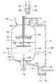
以下、図面に基づき本発明をさらに詳細に説明する。図1は、本発明の飲料および調味だし用抽出装置100の概略断面図である。
Hereinafter, the present invention will be described in more detail with reference to the drawings. FIG. 1 is a schematic cross-sectional view of a beverage and
<抽出室>
抽出室101は、原料中の有効成分を処理液で抽出することにより抽出液を得る室状のスペースであって、飲料および調味だし用抽出装置100の言わば本体部となるものである。この抽出室101は、後述の仕切りフィルタ108により上室部102と下室部103の上下二室に仕切られる。
<Extraction chamber>
The
<上室部>
上室部102は、後述の仕切りフィルタ108により仕切られた前記抽出室101の上側部である。この上室部102には、回転自在に攪拌翼104が支持されており、また処理液注入部105、原料注入部106および通気部115(バルブ122を有する)がそれぞれ付設されている。したがって、この上室部102において、原料(矢印B)と処理液(矢印A)が注入され、これらが攪拌翼104により攪拌されることにより、原料中の有効成分が処理液中に抽出されることになる。なお、図1では、処理液が液面117まで注入された状態を示している。
<Upper room>
The
該攪拌翼104は、回転自在に支持されるものであるが、より好ましくは昇降自在に支持されていることが好適である。これにより、攪拌位置の調節が容易となるからである。
The stirring
また、処理液注入部105、原料注入部106および通気部115の付設位置や形状は、特に限定されない。たとえば、処理液注入部105は、図1に示されているように攪拌翼104の上部に位置し、複数のノズルを有して処理液をシャワー状に注入するような形状のものとすることができる。このような形状のものを採用することにより、後述の仕切りフィルタ108上に均一に処理液を注入することができ、処理液が下室部103に滴下するのを有効に防止することができる。
Further, the attachment positions and shapes of the treatment
また、通気部115は、後述の圧力調節管109が付設される位置に近接させて付設することが好ましい。これら両者の間で良好に通気することができるようにするためである。
Moreover, it is preferable to attach the
<下室部>
下室部103は、後述の仕切りフィルタ108により仕切られた前記抽出室101の下側部である。この下室部103は、処理液が上記処理液注入部105から注入された後攪拌が終了するまでの間、空洞状に維持されるものである。
<Lower chamber>
The
このような下室部103には、抽出された抽出液を排出することができる排出部107が付設されており、該排出部107には該抽出液を装置外に取出す取出し部114が付設されている。したがって、前記上室部102において攪拌により有効成分が抽出された抽出液は、該攪拌終了後に上室部102からこの空洞状の下室部103に滴下し、この下室部103において排出部107に送られ取出し部114から取出されることになる。
Such a
ここで、下室部103における空洞状または空洞状態という表現は、真空であったり、抽出液が全く滴下していない状態のみを意味するものではなく、上室部102から滴下してくる抽出液を受け入れるのに充分なスペースを保持している状態を意味している。図1では、上室部102から滴下してきた処理液が液面118の高さまで一部溜まっており、液面118から仕切りフィルタ108までの間が空洞状となっている。
Here, the expression of a hollow shape or a hollow state in the
なお、この下室部103は、排出部107と連結し、バルブ110の開放操作で抽出液(処理液)を取出し部114から取出すことができる。また、液面センサ116(液体に浮かぶフロート120を有し、このフロートの位置により液面の高さを検知するもの)を付設することもでき、このセンサの作用により上記バルブ110の開放操作を調節したり、上記処理液注入部105からの処理液の注入量や後述の気体注入部112からの気体注入量を調節することによって、下室部103の空洞状態を保持することができる。
The
また、この下室部103は、上記上室部102と着脱することが可能なものとすることもでき、この場合該下室部103は図1に示したように取付け部111により上室部102に接続することができる。
Further, the
<処理液>
本発明における処理液は、原料から有効成分を抽出する溶媒となるものであって、その抽出後においては抽出液の溶媒となるものである。このような処理液としては、好ましくは水または熱水を用いることができる。しかし、飲食用に供されるものである限り、これらのみに限られるものではなく、たとえば脱酸素水、磁気水、アルコール等を使用することもできる。
<Processing liquid>
The treatment liquid in the present invention serves as a solvent for extracting an active ingredient from a raw material, and serves as a solvent for the extraction liquid after the extraction. As such a treatment liquid, water or hot water can be preferably used. However, as long as it is used for eating and drinking, it is not limited to these. For example, deoxygenated water, magnetic water, alcohol, etc. can be used.
このような処理液として特に優れているのは熱水であり、70℃以上、好ましくは90℃以上の熱水を用いることができる。このような熱水を用いることにより、下室部103の温度調節(すなわち気体の膨張による圧力調節)ができるとともに後述の仕切りフィルタ108との間で適度な表面張力が発生し、攪拌が終了するまでの間下室部103への抽出液の滴下を有効に防止することができる。
Hot water is particularly excellent as such a treatment liquid, and hot water at 70 ° C. or higher, preferably 90 ° C. or higher can be used. By using such hot water, the temperature of the lower chamber 103 (that is, pressure adjustment by gas expansion) can be adjusted, and an appropriate surface tension is generated between the
<原料>
本発明で用いる原料としては、その有効成分により飲料および調味だし用の原料となるものであればいずれのものも使用することができる。たとえば、それ自体が粒状物であるかまたは微粉や粉末を含む、コーヒー、茶、果実、鰹節、昆布、炒子等を挙げることができるが、これらのみに限られるものではない。
<Raw material>
As the raw material used in the present invention, any material can be used as long as it becomes a raw material for beverages and seasonings by its active ingredients. Examples include, but are not limited to, coffee, tea, fruit, bonito, kelp, fried egg, etc., which are themselves granular or contain fine powder or powder.
<仕切りフィルタ>
本発明の仕切りフィルタ108は、前記抽出室101を上室部102と下室部103の上下二室に仕切る作用を有するとともに、攪拌終了後において原料に含まれる粒状物が堆積する際のベース層となるものである。仮にこの仕切りフィルタがなければ、攪拌終了後原料中の粒状物は抽出室の底部に直接堆積し、この堆積層を通過させて抽出液を取出すには非常な困難を伴なうことになる。これに対して該仕切りフィルタ108を設けると、抽出液は攪拌終了後にこのフィルタ上に形成される粒状物の堆積層と該仕切りフィルタ108とを容易に通過して、下室部103へと容易に滴下することができ、もって抽出液の清澄度の向上と製造効率の向上の両者に資するものとなる。
<Partition filter>
The
このような仕切りフィルタ108は、金網で構成されていることが好ましいが、有孔板、ウェッジワイヤースクリーン等表面張力の作用を生じる濾過材であれば使用することができる。また、仕切りフィルタ108のメッシュは、40〜150メッシュが好ましく、特に仕切りフィルタ108が金網である場合、そのメッシュは、50〜100メッシュ、好ましくは50〜80メッシュ、さらに好ましくは50〜60メッシュである。このような大きさのメッシュを有していることにより、前記処理液との間に表面張力が発生し、下室部の圧力(空洞容積)の減少を防止する後述の手段と相俟って下室部を空洞状に維持することができることとなる。
Such a
該仕切りフィルタ108のメッシュが150メッシュを超えると、攪拌終了後の抽出液の滴下に長時間を要し製造効率を著しく低下することになる。一方、40メッシュ未満の場合には処理液との間で適度な表面張力を得ることができなくなり、結果的に処理液が下室部103に滴下することになるので下室部103を空洞状に維持することができなくなる。
When the mesh of the
<圧力調節管および気体注入部>
本発明の圧力調節管109は、前記排出部107と前記上室部102とを接続させ、前記上室部102および下室部103内の圧力を調節する作用(下室部103を空洞状に保持する作用)を有するものである。このような圧力調節管109は、接続部113において排出部107に接続される。
<Pressure control tube and gas injection part>
The
また、このような圧力調節管109の少なくとも一部は、図1に示すように、上室部102との接続側が高くなるように水平方向に対して0.5〜30°の勾配を持つような状態で配置されていることが好ましい。該勾配は、より好ましくは1〜10°、さらに好ましくは1〜5°である。該圧力調節管109が、このような勾配を有することにより、その勾配状態にある箇所において後述の気体注入部112が接続されることにより、該気体注入部112から注入される気体の作用を有効に発現させることが可能となる。
In addition, as shown in FIG. 1, at least a part of the
一方、圧力調節管109と上室部102との接続は、該上室部102中の処理液が該上室部102から流出しないように上室部102の上部において接続することが好ましい。
On the other hand, the
一方、圧縮空気や窒素、二酸化炭素等の気体(矢印C)を注入する気体注入部112は、圧力調節管109に付設されており、その付設箇所は前記のような0.5〜30°の勾配状態にある圧力調節管109に対して接続されていることが好ましい。気体注入部112をこのような位置に付設することにより、気体注入部112から圧縮空気のような気体を少量注入した場合、該気体は圧力調節管109の勾配に従って上室部102との接続側に流れ、かつ上室部102との接続部の方向に向かって該圧力調節管109を気泡121状になって上昇することとなり、このように注入された気体が上室部102との接続側に気泡状となって上昇することにより、その際に生じる圧力の影響で前記下室部103からの気体(空気)の排出部107側への流出を防止する作用を示し、もって前記下室部103内の圧力(空洞容積)の減少を防止することが可能となる。
On the other hand, the
このため、前記圧力調節管109の勾配が0.5°未満の場合には、気体注入部112から注入された気体を上室部102との接続側に有効に流入させることができなくなり、また30°を超える場合には、注入された気体の上室部102との接続側への流入速度が速くなりすぎ、前記のような圧力が有効に得られず前記下室部103からの気体の流出を有効に防止し得なくなる場合がある。
For this reason, when the gradient of the
さらに、該気体注入部112をこのような位置に付設したことにより、該気体注入部112から注入された該気体が前記103側に流入する場合においても、該気体は圧力調節管109と排出部107を介して下室部103内に注入されることとなるため、このような気体を下室部103に直接導入する場合に比べ、前記仕切りフィルタ108の振動を有効に防止することができる。すなわち、前記仕切りフィルタ108が注入された気体により振動すると、表面張力のバランスが崩れ、処理液がその振動により下室部103へ滴下することになるが、この振動を防止したことによりその滴下を有効に防止することが可能となった。
Furthermore, by providing the
以下、さらにこの圧力調節管109と気体注入部112とによる圧力調節作用(下室部103の空洞容積の減少を防止する作用)について説明する。
Hereinafter, a pressure adjusting action (an action for preventing a decrease in the cavity volume of the lower chamber 103) by the
まず、処理液が下室部103に滴下しないためには、以下の関係式(1)を満足することが必要になる。すなわち、
P1+G<P2+H・・・(1)
ここで、上記式(1)中、P1は上室部102の圧力(空洞部の圧力)、P2は下室部103の圧力(空洞部の圧力)、Gは仕切りフィルタ上にかかる処理液と原料との重量圧、Hは処理液と仕切りフィルタ間の表面張力をそれぞれ意味する。
First, it is necessary to satisfy the following relational expression (1) so that the treatment liquid does not drop into the
P1 + G <P2 + H (1)
Here, in the above formula (1), P1 is the pressure in the upper chamber portion 102 (pressure in the cavity portion), P2 is the pressure in the lower chamber portion 103 (pressure in the cavity portion), and G is the treatment liquid on the partition filter. The weight pressure with the raw material, H means the surface tension between the treatment liquid and the partition filter.
上記関係式(1)において、Gは処理液と原料の使用量により決定され、またHは仕切りフィルタのメッシュと処理液の種類および温度により決定される。したがって、GおよびHは条件により容易に変動するため、操作の利便性および確実性の観点から、P1およびP2を調節することがより有効な手段となる。そして、このP1およびP2を調節するのがこの圧力調節管109および気体注入部112の作用である。
In the above relational expression (1), G is determined by the amount of processing liquid and raw material used, and H is determined by the partition filter mesh and the type and temperature of the processing liquid. Therefore, since G and H easily vary depending on conditions, adjusting P1 and P2 is a more effective means from the viewpoint of convenience of operation and certainty. The
すなわち、バルブ110を閉じた状態で処理液注入部105より処理液を上室部102に注入すると、少量の処理液が下室部103に滴下する。そして、このように下室部103に滴下した少量の処理液は、排出部107を通り圧力調節管109に流入し、液面119の高さまで圧力調節管109を満たす。
That is, when the processing liquid is injected into the
一方、これと同時的に気体注入部112から注入された気体は、処理液で満たされた圧力調節管109中を上室部102との接続側に向かって気泡121となって上昇するとともに、下室部103から気体(空気)が排出部107および圧力調節管109側へ流入するのを防止する。
On the other hand, the gas injected from the
このようにして、圧力調節管109中の液面119の高さを有する処理液の水頭圧と、気体注入部112から注入される気体の作用(気泡となって上昇する際に生じる圧力)とにより、下室部103の圧力P2(空洞容積)の減少は防止されることになる。
In this way, the head pressure of the treatment liquid having the height of the
そして、このように減少を防止された圧力P2と前記仕切りフィルタによる表面張力Hとが相俟って、前記式(1)が成立し処理液の下室部103内への滴下を有効に防止することができる。
Then, the pressure P2 thus prevented from decreasing and the surface tension H by the partition filter combine to effectively prevent the treatment liquid from dropping into the
なお、この場合、下室部103内の気体の温度は、熱水である処理液の影響により上昇し、これにより気体の体積が膨張することによって圧力P2を高めることができる。
In this case, the temperature of the gas in the
一方、攪拌終了後においては、バルブ110を開放することにより下室部103内の圧力P2を下げるとともに、通気部115より加圧した気体を上室部102に注入することにより上室部102の圧力P1を高める。この際、圧力調節管109のバルブ127を閉じておくことにより、上室部102の圧力の上昇が下室部103に及ぶのを有効に防止することができ、上室部102と下室部103の圧力差を大きくすることができる。これにより、抽出液の下室部103への滴下をさらに助長することが可能になる(すなわち、前記式(1)において左辺の方を大きくする)。
On the other hand, after the stirring is finished, the pressure P2 in the
さらに、高濃度な抽出液を得るために高温および高圧下で抽出する場合は、通気部115から圧縮空気などの気体を注入することを除き、基本的に前記と同様の操作を行なうことにより下室部103を空洞状に保持したまま抽出することができる。
Furthermore, when extracting at a high temperature and high pressure in order to obtain a highly concentrated extract, the operation is basically performed by performing the same operation as described above except that a gas such as compressed air is injected from the
すなわち、圧力調節管109は、前記の通り該上室部102の上部において接続されており、高温および高圧による圧力P1の上昇分はこの圧力調節管109を通じて接続部113および排出部107を介して下室部103にまで伝播し、圧力P2も上昇することとなる。このため、結果的に抽出室101全体が高温および高圧状態に保たれ、下室部103を空洞状に保持しつつ高温および高圧下での抽出が可能となる。
That is, the
以上のようにして、上記上室部と下室部の圧力P1、P2は、気体注入部112から注入される気体の作用および圧力調節管109の液面高さ119による水頭圧、および前記仕切りフィルタ108による表面張力Hとの相乗作用により前記式(1)の関係が保たれる。そして、この関係の下、処理液は上室部102において攪拌されている間下室部103に滴下することが有効に防止され、もって下室部103は前記の通り空洞状に維持される。そして、攪拌終了後においては、原料中の粒状物が静置により粒子径の大きなものから順に該仕切りフィルタ108上に堆積し、これらの堆積物が精密濾過層のような作用を奏し得ることになる。したがって、処理液(抽出液)がこの堆積物と該仕切りフィルタを通過して下室部103へと滴下することにより、極めて清澄度の高い抽出液を極めて高い製造効率の下に得ることができることとなる。
As described above, the pressures P1 and P2 of the upper chamber portion and the lower chamber portion are the effects of the gas injected from the
<その他>
本発明の飲料および調味だし用抽出装置100の上室部102には、圧縮空気導入部123(バルブ125を有する)および低圧スチーム導入部124(バルブ126を有する)を設けることができる。
<Others>
The
これにより、仕切りフィルタ108上に堆積しているポーラス状の堆積物に対して、低圧スチーム導入部124より低圧スチーム(矢印D)を通過させると、該堆積層が保有する水分をさらに効率良く排出させることができる。また、この低圧スチームを通過させることにより該堆積層の温度が上昇し、その後に圧縮空気導入部123より圧縮空気(矢印E)を導入すると、該堆積層はその保有熱により水分がさらに蒸発するとともに温度も低下する。
As a result, when the low-pressure steam (arrow D) is passed through the low-pressure
その後、さらに攪拌翼104により該堆積層を攪拌すると、該堆積層を解砕した状態で排出することができる。これにより、その後の搬送や後処理をさらに容易に行なえるようになる。
Thereafter, when the deposited layer is further stirred by the
なお、該堆積層の水分の含有量を極力低くすることで、腐敗を抑えることができるとともに、乾燥処理する場合の熱量を大幅に削減することができる。 It should be noted that by reducing the water content of the deposited layer as much as possible, it is possible to suppress spoilage and to greatly reduce the amount of heat in the drying process.
以下、実施例を挙げて本発明をより詳細に説明するが、本発明はこれらに限定されるものではない。 EXAMPLES Hereinafter, although an Example is given and this invention is demonstrated in detail, this invention is not limited to these.
<実施例1>
仕切りフィルタ108として0.19m2の面積を有する50メッシュの金網を付設した飲料および調味だし用抽出装置100(抽出室101の容量130l)の処理液注入部105より、処理液として90℃の熱水を注入した。なお、このとき排出部107のバルブ110は閉止状態とした。
<Example 1>
A 90 ° C. heat as a processing liquid is obtained from the processing
上記熱水の一部は、仕切りフィルタ108を通過し下室部103に滴下し、その後排出部107を通じて圧力調節管109にまで流入した。その液面119は、上室部102の液面117とほぼ同じ高さとなった。
Part of the hot water passed through the
一方、上記のように熱水を注入する前から、気体注入部112より少量の圧縮空気を注入し続けた。該気体注入部112が付設されている圧力調節管109は、上室部102との接続側が高くなるように3°の勾配を持つように配置されており、このため注入された圧縮空気は上室部102との接続側に流入し、気泡121となって圧力調節管109を上昇し、上室部102の通気部115を通じて系外へ排出された。
On the other hand, a small amount of compressed air was continuously injected from the
前記のように、熱水が下室部103へと滴下するのは、前記式(1)で左辺の方が大きくなるためであるが、圧力調節管109の液面119の上昇により水頭圧が上昇するとともに上記気体注入部112から注入される圧縮空気の作用(気泡となって上昇する際に生じる圧力)により、下室部103の圧力P2が減少するのが防止され(空洞容積の減少が抑制され)、熱水の滴下が防止されて下室部103の空洞状態は保持される。
As described above, the hot water is dripped into the
熱水の注入量が100kgになったとき、熱水の注入を停止した。その後、攪拌翼104を40rpmの速度で回転させながら、原料注入部106より鰹節(粒状のもの)を徐々に投入し、合計10kgの鰹節を原料として投入した。
When the amount of hot water injected reached 100 kg, the hot water injection was stopped. After that, while rotating the
なお、この場合の上室部102の圧力P1は0MPa(ゲージ圧)であり、下室部103の圧力P2は0.005MPa(ゲージ圧)であり、原料と処理液との重量圧Gは0.0055MPa(ゲージ圧)であった。また下室部103に取付けた液面センサ116により下室部103が空洞状に保持されていることを確認した。
In this case, the pressure P1 in the
また、処理液と仕切りフィルタ間の表面張力Hは、以下の状況により約0.0005MPa(ゲージ圧)以上であることを確認した。すなわち、上記のように熱水供給の進行により上室部102の液面117が上昇するとともに、下室部103への滴下が生じはじめる。滴下した熱水は、排出部107を通り、圧力調節管109に流入する。一方、気体注入部112より注入した少量の圧縮空気は圧力調節管109の熱水中を気泡121状となって上昇する。
Further, it was confirmed that the surface tension H between the treatment liquid and the partition filter was about 0.0005 MPa (gauge pressure) or more under the following conditions. That is, as described above, the
そして、熱水供給が更に進み上室部102の液面117も更に上昇するが、下室部103に設置した液面センサ116は液面118の上昇を検知せず空洞状態を示し、下室部103は空洞状態に維持される。
The hot water supply further advances and the
またこのとき、圧力調節管109の液面119の高さと上室部102の液面117の高さとは、ほぼ同一の高さを示す。この状態は、下室部103の上部、すなわち仕切りフィルタ108の下面に空気が溜まり、下室部103の底部に溜まる熱水は排出部107を通り圧力調節管109を液面119の高さまで満たし、また気体注入部112より注入した少量の圧縮空気は圧力調節管109の熱水中を気泡121状に上昇する際、下室部103の空気を加圧状態に保つことを示す。
At this time, the height of the
以上の状態を維持するのは、仕切りフィルタ108の金網目に生じる水膜(処理液である熱水による膜)の表面張力によるものであると考えられ、上室部102の圧力P1と重量圧Gによる下室部103への熱水の滴下を防止するとともに、下室部103に溜まる空気の放出も防ぐ。したがって、前記式(1)の条件が具備されていることが確認できた。
It is considered that the above state is maintained by the surface tension of the water film (film of hot water that is the processing liquid) generated in the metal mesh of the
その後20分間攪拌を続けた後、該攪拌を停止し、1分間静置させた。静置後、仕切りフィルタ108上(上室部102側)には、原料である鰹節に含まれていた粒状物が粒子径の大きいものから順に堆積していることが観察された。なお、該観察は、該仕切りフィルタ108上に堆積していた抽出粕を観察することにより行なった。
Thereafter, stirring was continued for 20 minutes, and then the stirring was stopped and allowed to stand for 1 minute. After standing, it was observed that the particulate matter contained in the koji koji, which is the raw material, was deposited on the partition filter 108 (on the
次いで、バルブ110を開放状態とすると下室部103の圧力P2が低下すると同時に、鰹節の有効成分を抽出した抽出液が上室部102から粒状物の堆積層および仕切りフィルタ108を通過して、下室部103へと滴下し、排出部107から排出され、バルブ110を通して取出し部114から取出された。この取出された抽出液を目視観察すると、粒状物、特に微粉や粉末の混入が全くなく、極めて清澄度の高いものであった。
Next, when the
<実施例2>
実施例1で用いた仕切りフィルタに代えて、60メッシュの金網を用いることを除き、他は全て実施例1と同様にして抽出液を得た。このようにして得られた抽出液は、実施例1のものと同様に極めて優れた清澄度を有していた。
<Example 2>
An extract was obtained in the same manner as in Example 1 except that a 60-mesh wire mesh was used in place of the partition filter used in Example 1. The extract obtained in this manner had a very good clarity as in Example 1.
<実施例3>
実施例1で用いた仕切りフィルタに代えて、140メッシュの金網を用いることを除き、他は全て実施例1と同様にして抽出液を得た。このようにして得られた抽出液は、実施例1のものと同様に極めて優れた清澄度を有していた。
<Example 3>
An extract was obtained in the same manner as in Example 1 except that a 140-mesh wire mesh was used instead of the partition filter used in Example 1. The extract obtained in this manner had a very good clarity as in Example 1.
<比較例1>
実施例1で用いた仕切りフィルタに代えて、30メッシュの金網を用いることを除き、他は全て実施例1と同様にして抽出液を得た。このようにして得られた抽出液には、微粉が多数混入しており極めて低い清澄度を有し商品価値を喪失していた。
<Comparative Example 1>
An extract was obtained in the same manner as in Example 1 except that a 30-mesh wire mesh was used instead of the partition filter used in Example 1. The extract thus obtained contained a large number of fine powders, had a very low clarity, and lost commercial value.
<比較例2>
実施例1で用いた仕切りフィルタに代えて、160メッシュの金網を用いることを除き、他は全て実施例1と同様にして抽出液を得た。しかし、得られた抽出液は、極めて少量であるにもかかわらず、排出するのに30分以上の時間を要した。これに対して、実施例1の抽出液の量は約90lであるにもかかわらず、排出に要した時間は6分であった。したがって、この比較例のものは極めて悪い製造効率を有するものであった。
<Comparative example 2>
An extract was obtained in the same manner as in Example 1 except that a 160-mesh wire mesh was used in place of the partition filter used in Example 1. However, although the obtained extract was very small, it took 30 minutes or more to be discharged. On the other hand, although the amount of the extract of Example 1 was about 90 l, the time required for discharging was 6 minutes. Therefore, this comparative example had extremely poor production efficiency.
<比較例3>
気体注入部112を通じての気体の注入を一切行なわないことを除き、他は全て実施例1と同様にして抽出液を得た。得られた抽出液には、微粉が多数混入しており清澄度を高めるための後工程(濾過工程)を要した。
<Comparative Example 3>
An extract was obtained in the same manner as in Example 1 except that no gas was injected through the
これは、下室部103の空洞状が維持されず、処理液とともに原料の微粉が攪拌時に下室部103に多量に侵入したためと考えられる。これにより、下室部103の空洞状態を維持するためには、処理液と仕切りフィルタ間の表面張力Hだけではなく、気体注入部112から注入された気体が圧力調節管109を気泡状となって上昇する際の圧力により下室部103の圧力P2を維持する必要があることがわかる。
This is presumably because the hollow shape of the
今回開示された実施の形態および実施例はすべての点で例示であって制限的なものではないと考えられるべきである。本発明の範囲は上記した説明ではなくて特許請求の範囲によって示され、特許請求の範囲と均等の意味および範囲内でのすべての変更が含まれることが意図される。 It should be understood that the embodiments and examples disclosed herein are illustrative and non-restrictive in every respect. The scope of the present invention is defined by the terms of the claims, rather than the description above, and is intended to include any modifications within the scope and meaning equivalent to the terms of the claims.
100 飲料および調味だし用抽出装置、101 抽出室、102 上室部、103 下室部、104 攪拌翼、105 処理液注入部、106 原料注入部、107 排出部、108 仕切りフィルタ、109 圧力調節管、110,122,125,126,127 バルブ、111 取付け部、112 気体注入部、113 接続部、114 取出し部、115 通気部、116 液面センサ、117,118,119 液面、120 フロート、121 気泡、123 圧縮空気導入部、124 低圧スチーム導入部。
DESCRIPTION OF
Claims (5)
前記仕切りフィルタのメッシュは40〜150メッシュであり、
前記排出部と前記上室部にはこれら両者を接続させ、前記抽出室内の圧力を調節するための圧力調節管が付設されており、
前記圧力調節管には気体を注入する気体注入部が付設されていることを特徴とする、飲料および調味だし用抽出装置。 An extraction chamber that obtains an extract by extracting an active ingredient in the raw material with a processing solution, a partition filter that divides the extraction chamber into two upper and lower chambers, an upper chamber portion and a lower chamber portion, and is freely rotatable in the upper chamber portion A supported stirring blade, a processing liquid injection part capable of injecting a processing liquid into the upper chamber part, a raw material injection part capable of injecting a raw material into the upper chamber part, and A beverage and seasoning extraction device having a discharge part that can be discharged from a chamber part, and a take-out part that can take out the extract from the discharge part,
The partition filter mesh is 40-150 mesh,
The discharge part and the upper chamber part are both connected to each other, and a pressure adjusting pipe for adjusting the pressure in the extraction chamber is attached,
A beverage and seasoning extraction device, wherein a gas injection part for injecting a gas is attached to the pressure control pipe.
前記下室部は、処理液が注入された後攪拌が終了するまでの間、空洞状に維持されるとともに、
前記原料中の粒状物は、攪拌終了後に処理液を静置すると前記仕切りフィルタの上室部側に粒子径の大きなものから順に堆積すること、を特徴とする飲料および調味だし用抽出方法。 An extraction method using the beverage according to claim 1 and a seasoning extractor,
The lower chamber is maintained in a hollow shape until the stirring is finished after the treatment liquid is injected,
The extraction method for beverages and seasonings, characterized in that the granular materials in the raw material are deposited in order from the particles having the largest particle size on the upper chamber side of the partition filter when the treatment liquid is allowed to stand after completion of stirring.
Priority Applications (1)
| Application Number | Priority Date | Filing Date | Title |
|---|---|---|---|
| JP2003278376A JP3693664B2 (en) | 2003-07-23 | 2003-07-23 | Beverage and seasoning extraction apparatus and extraction method |
Applications Claiming Priority (1)
| Application Number | Priority Date | Filing Date | Title |
|---|---|---|---|
| JP2003278376A JP3693664B2 (en) | 2003-07-23 | 2003-07-23 | Beverage and seasoning extraction apparatus and extraction method |
Publications (2)
| Publication Number | Publication Date |
|---|---|
| JP2005040387A true JP2005040387A (en) | 2005-02-17 |
| JP3693664B2 JP3693664B2 (en) | 2005-09-07 |
Family
ID=34264801
Family Applications (1)
| Application Number | Title | Priority Date | Filing Date |
|---|---|---|---|
| JP2003278376A Expired - Fee Related JP3693664B2 (en) | 2003-07-23 | 2003-07-23 | Beverage and seasoning extraction apparatus and extraction method |
Country Status (1)
| Country | Link |
|---|---|
| JP (1) | JP3693664B2 (en) |
Cited By (12)
| Publication number | Priority date | Publication date | Assignee | Title |
|---|---|---|---|---|
| KR100691423B1 (en) | 2006-04-07 | 2007-03-12 | 이상민 | Electric herb extractor having rotary type agitation device |
| KR100936409B1 (en) | 2008-03-25 | 2010-01-12 | 박용묵 | A nutche filter inspectable filtering extract |
| EP2446786A2 (en) * | 2009-06-26 | 2012-05-02 | Amorepacific Corporation | Positive and negative extraction device and extraction method |
| CN103055533A (en) * | 2012-07-13 | 2013-04-24 | 桂林市振达生物科技有限责任公司 | High-efficiency traditional Chinese medicine extracting tank |
| CN105126384A (en) * | 2015-09-23 | 2015-12-09 | 西安森兰科贸有限责任公司 | Plant extraction filter and extraction filter system |
| JP2016029937A (en) * | 2014-07-30 | 2016-03-07 | 日本洗浄機株式会社 | Apparatus for producing soup stock |
| JP2016042841A (en) * | 2014-08-25 | 2016-04-04 | 日本洗浄機株式会社 | Soup stock production device and method |
| JP2016042842A (en) * | 2014-08-25 | 2016-04-04 | 日本洗浄機株式会社 | Soup stock production device and method |
| JP2016220550A (en) * | 2015-05-27 | 2016-12-28 | アサヒ飲料株式会社 | Method for manufacturing container-packed coffee drink, container-packed coffee drink, and method for improving taste of container-packed coffee drink |
| KR20210097462A (en) * | 2020-01-30 | 2021-08-09 | (주)세준에프앤비 | Agitated extractor for food contatining starch |
| KR20210108256A (en) * | 2020-02-25 | 2021-09-02 | 김보미 | Vacuum extraction and enrichment system for food |
| KR102564690B1 (en) * | 2022-03-18 | 2023-08-08 | 주식회사 에코위더스 | Smart induction cooking device and system including the device |
Citations (2)
| Publication number | Priority date | Publication date | Assignee | Title |
|---|---|---|---|---|
| JPH11221153A (en) * | 1998-02-06 | 1999-08-17 | Asahi Inryo Kk | Method and device for extracting tea drink |
| JP2002177147A (en) * | 2000-12-12 | 2002-06-25 | Izumi Food Machinery Co Ltd | Beverage extraction device |
-
2003
- 2003-07-23 JP JP2003278376A patent/JP3693664B2/en not_active Expired - Fee Related
Patent Citations (2)
| Publication number | Priority date | Publication date | Assignee | Title |
|---|---|---|---|---|
| JPH11221153A (en) * | 1998-02-06 | 1999-08-17 | Asahi Inryo Kk | Method and device for extracting tea drink |
| JP2002177147A (en) * | 2000-12-12 | 2002-06-25 | Izumi Food Machinery Co Ltd | Beverage extraction device |
Cited By (15)
| Publication number | Priority date | Publication date | Assignee | Title |
|---|---|---|---|---|
| KR100691423B1 (en) | 2006-04-07 | 2007-03-12 | 이상민 | Electric herb extractor having rotary type agitation device |
| KR100936409B1 (en) | 2008-03-25 | 2010-01-12 | 박용묵 | A nutche filter inspectable filtering extract |
| EP2446786A2 (en) * | 2009-06-26 | 2012-05-02 | Amorepacific Corporation | Positive and negative extraction device and extraction method |
| EP2446786A4 (en) * | 2009-06-26 | 2015-01-07 | Amorepacific Corp | Positive and negative extraction device and extraction method |
| CN103055533A (en) * | 2012-07-13 | 2013-04-24 | 桂林市振达生物科技有限责任公司 | High-efficiency traditional Chinese medicine extracting tank |
| JP2016029937A (en) * | 2014-07-30 | 2016-03-07 | 日本洗浄機株式会社 | Apparatus for producing soup stock |
| JP2016042841A (en) * | 2014-08-25 | 2016-04-04 | 日本洗浄機株式会社 | Soup stock production device and method |
| JP2016042842A (en) * | 2014-08-25 | 2016-04-04 | 日本洗浄機株式会社 | Soup stock production device and method |
| JP2016220550A (en) * | 2015-05-27 | 2016-12-28 | アサヒ飲料株式会社 | Method for manufacturing container-packed coffee drink, container-packed coffee drink, and method for improving taste of container-packed coffee drink |
| CN105126384A (en) * | 2015-09-23 | 2015-12-09 | 西安森兰科贸有限责任公司 | Plant extraction filter and extraction filter system |
| KR20210097462A (en) * | 2020-01-30 | 2021-08-09 | (주)세준에프앤비 | Agitated extractor for food contatining starch |
| KR102371536B1 (en) | 2020-01-30 | 2022-03-08 | (주)세준에프앤비 | Agitated extractor for food contatining starch |
| KR20210108256A (en) * | 2020-02-25 | 2021-09-02 | 김보미 | Vacuum extraction and enrichment system for food |
| KR102392009B1 (en) * | 2020-02-25 | 2022-04-29 | 김보미 | Vacuum extraction and enrichment system for food |
| KR102564690B1 (en) * | 2022-03-18 | 2023-08-08 | 주식회사 에코위더스 | Smart induction cooking device and system including the device |
Also Published As
| Publication number | Publication date |
|---|---|
| JP3693664B2 (en) | 2005-09-07 |
Similar Documents
| Publication | Publication Date | Title |
|---|---|---|
| JP3693664B2 (en) | Beverage and seasoning extraction apparatus and extraction method | |
| JP5865265B2 (en) | Beverage extractor | |
| EP1231842B1 (en) | Methods and systems for forming concentrated consumable extracts | |
| RU2584111C2 (en) | Beverage preparation method and system and beverage preparation cartridge | |
| RU2546426C2 (en) | Portion capsule for beverage preparation with portion capsule | |
| EP2444339A1 (en) | A capsule for preparation of a beverage | |
| US9961917B2 (en) | Brewing system | |
| KR20100135785A (en) | A beverage cartridge | |
| JP2010500100A5 (en) | ||
| CA2513719A1 (en) | Cartridge and method for the preparation of beverages | |
| JP2010075705A (en) | Brewing device for coffee and method for producing coffee beverage with brewing device | |
| US20180007926A1 (en) | System and method of cold brewing coffee | |
| US20060174779A1 (en) | Coffee maker | |
| JP6541419B2 (en) | Solid-liquid extraction device and solid-liquid extraction method | |
| JP4240264B2 (en) | Manufacturing method of industrial espresso coffee | |
| EP3297450B1 (en) | Process for producing barley tea | |
| JP4404585B2 (en) | Method for producing coffee liquid | |
| EP1787523A2 (en) | Methods and systems for forming concentrated consumable extracts | |
| TW202247892A (en) | Extraction cell | |
| JP4440014B2 (en) | Coffee products | |
| JP2005117997A (en) | Mass production coffee beverage, and method and device for extracting the same |
Legal Events
| Date | Code | Title | Description |
|---|---|---|---|
| A977 | Report on retrieval |
Free format text: JAPANESE INTERMEDIATE CODE: A971007 Effective date: 20050525 |
|
| TRDD | Decision of grant or rejection written | ||
| A01 | Written decision to grant a patent or to grant a registration (utility model) |
Free format text: JAPANESE INTERMEDIATE CODE: A01 Effective date: 20050531 |
|
| A61 | First payment of annual fees (during grant procedure) |
Free format text: JAPANESE INTERMEDIATE CODE: A61 Effective date: 20050621 |
|
| R150 | Certificate of patent or registration of utility model |
Free format text: JAPANESE INTERMEDIATE CODE: R150 |
|
| FPAY | Renewal fee payment (event date is renewal date of database) |
Free format text: PAYMENT UNTIL: 20080701 Year of fee payment: 3 |
|
| FPAY | Renewal fee payment (event date is renewal date of database) |
Free format text: PAYMENT UNTIL: 20090701 Year of fee payment: 4 |
|
| FPAY | Renewal fee payment (event date is renewal date of database) |
Free format text: PAYMENT UNTIL: 20100701 Year of fee payment: 5 |
|
| FPAY | Renewal fee payment (event date is renewal date of database) |
Free format text: PAYMENT UNTIL: 20110701 Year of fee payment: 6 |
|
| FPAY | Renewal fee payment (event date is renewal date of database) |
Free format text: PAYMENT UNTIL: 20110701 Year of fee payment: 6 |
|
| FPAY | Renewal fee payment (event date is renewal date of database) |
Free format text: PAYMENT UNTIL: 20120701 Year of fee payment: 7 |
|
| FPAY | Renewal fee payment (event date is renewal date of database) |
Free format text: PAYMENT UNTIL: 20120701 Year of fee payment: 7 |
|
| S531 | Written request for registration of change of domicile |
Free format text: JAPANESE INTERMEDIATE CODE: R313531 |
|
| FPAY | Renewal fee payment (event date is renewal date of database) |
Free format text: PAYMENT UNTIL: 20120701 Year of fee payment: 7 |
|
| R350 | Written notification of registration of transfer |
Free format text: JAPANESE INTERMEDIATE CODE: R350 |
|
| FPAY | Renewal fee payment (event date is renewal date of database) |
Free format text: PAYMENT UNTIL: 20120701 Year of fee payment: 7 |
|
| FPAY | Renewal fee payment (event date is renewal date of database) |
Free format text: PAYMENT UNTIL: 20130701 Year of fee payment: 8 |
|
| R250 | Receipt of annual fees |
Free format text: JAPANESE INTERMEDIATE CODE: R250 |
|
| LAPS | Cancellation because of no payment of annual fees |