JP2005018355A - Onboard electronic toll collection unit - Google Patents
Onboard electronic toll collection unit Download PDFInfo
- Publication number
- JP2005018355A JP2005018355A JP2003181296A JP2003181296A JP2005018355A JP 2005018355 A JP2005018355 A JP 2005018355A JP 2003181296 A JP2003181296 A JP 2003181296A JP 2003181296 A JP2003181296 A JP 2003181296A JP 2005018355 A JP2005018355 A JP 2005018355A
- Authority
- JP
- Japan
- Prior art keywords
- temperature
- storage medium
- measured
- unit
- automatic toll
- Prior art date
- Legal status (The legal status is an assumption and is not a legal conclusion. Google has not performed a legal analysis and makes no representation as to the accuracy of the status listed.)
- Pending
Links
Images


Abstract
Description
【0001】
【発明の属する技術分野】
本発明は、自動料金収受車載器に関し、詳しくは、無線通信によって高速道路等の有料道路の料金収受を行う自動料金収受システム(Electronic Toll Collection System、「ETC」ともいう。)を構成するETC車載器に関するものである。
【0002】
【従来の技術】
従来、無線通信によって高速道路等の有料道路の料金収受を行う自動料金収受車載器が知られている(例えば、特許文献1参照。)。
【0003】
図13に示す特許文献1に開示されたDSRC車載器(自動料金収受車載器)900は、ETCで採用される狭域通信(Dedicated Short Range Communications、「DSRC」ともいう。)を行うものである。DSRC車載器900は、ICカード10を収納するICカード収納部910と、ICカード10の電極部に接続されるコンタクト部920と、回路基板930に配設された温度センサ940、950と、温度センサ940、950によって計測された温度がICカード10の耐熱温度範囲を逸脱した場合に警報を発する警報手段960、970とを備えている。
【0004】
前述のように構成された、DSRC車載器900においては、ICカード収納部910に収容されたICカード10の温度が耐熱温度を超えた場合に、警報手段960、970を介して警報が発せられる。
【0005】
【特許文献1】
特開2000−276625号公報(第5頁、第1−2図)
【0006】
【発明が解決しようとする課題】
しかしながら、このような従来のDSRC車載器900は、ICカード収納部910に収容されたICカード10等の記録媒体の温度変化による変形や破壊を防止することができないといった問題があった。
【0007】
本発明は、このような問題を解決するためになされたもので、収容された記録媒体の温度変化による変形や破壊を防止することができる自動料金収受車載器を提供するものである。
【0008】
【課題を解決するための手段】
本発明の自動料金収受車載器は、記憶媒体を収容する記憶媒体収容手段と、前記記憶媒体収容手段に収容された記憶媒体付近の温度を計測する温度計測手段と、前記記憶媒体収容手段に収容された記憶媒体の温度を変化させる温度変化手段と、前記温度計測手段によって計測された計測温度に応じて前記温度変化手段の作動状態を調節する作動状態調節手段とを備えた構成を有している。
この構成により、記憶媒体収容手段に収容された記録媒体付近の温度に応じて、温度変化手段によって記録媒体の温度を変化させるため、収容された記録媒体の温度変化による変形や破壊を防止することができる。
【0009】
また、本発明の自動料金収受車載器は、前記温度変化手段が、前記記憶媒体収容手段に収容された記憶媒体を冷却する冷却装置よりなる構成を有している。
この構成により、記憶媒体収容手段に収容された記憶媒体付近の温度に応じて、温度変化手段によって記憶媒体を冷却するため、収容された記憶媒体の温度変化による変形や破壊を防止することができる。
【0010】
また、本発明の自動料金収受車載器は、前記冷却装置が、前記記憶媒体収容手段に収容された記憶媒体に向けて送風する冷却ファンを有している。
この構成により、記憶媒体収容手段に収容された記憶媒体付近の温度に応じて、冷却ファンによって記憶媒体を冷却するため、収容された記憶媒体の温度変化による変形や破壊を防止することができる。
【0011】
また、本発明の自動料金収受車載器は、前記作動状態調節手段による作動状態の調節が、前記計測温度が予め定められた冷却温度以上になった場合には、前記温度変化手段を作動させ、前記計測温度が前記冷却温度未満になった場合には、前記温度変化手段を停止させるよう行われる構成を有している。
この構成により、記憶媒体収容手段に収容された記憶媒体付近の温度が所定の冷却温度以上になった場合には、温度変化手段によって記憶媒体を冷却するため、収容された記録媒体の温度変化による変形や破壊を防止することができる。
【0012】
また、本発明の自動料金収受車載器は、前記温度変化手段は、前記記憶媒体収容手段に収容された記憶媒体を加熱する加熱装置よりなる構成を有している。
この構成により、記憶媒体収容手段に収容された記憶媒体付近の温度に応じて、温度変化手段によって記憶媒体を加熱するため、収容された記憶媒体の温度変化による変形や破壊を防止することができる。
【0013】
また、本発明の自動料金収受車載器は、前記加熱装置が、前記記憶媒体収容手段に収容された記憶媒体に向けて熱を放射するヒータを有している。
この構成により、記憶媒体収容手段に収容された記憶媒体付近の温度に応じて、ヒータによって記憶媒体を加熱するため、収容された記憶媒体の温度変化による変形や破壊を防止することができる。
【0014】
また、本発明の自動料金収受車載器は、前記作動状態調節手段による作動状態の調節が、前記計測温度が予め定められた加熱温度以下になった場合には、前記温度変化手段を作動させ、前記計測温度が前記加熱温度を超過した場合には、前記温度変化手段を停止させるよう行われる構成を有している。
この構成により、記憶媒体収容手段に収容された記憶媒体付近の温度が所定の加熱温度以下になった場合には、温度変化手段によって記憶媒体を加熱するため、収容された記録媒体の温度変化による変形や破壊を防止することができる。
【0015】
また、本発明の自動料金収受車載器は、前記温度変化手段が、ペルチェ素子を有している。
この構成により、記憶媒体収容手段に収容された記憶媒体付近の温度に応じて、ペルチェ素子によって記憶媒体を冷却または加熱するため、収容された記憶媒体の温度変化による変形や破壊を防止することができる。
【0016】
また、本発明の自動料金収受車載器は、前記作動状態調節手段による作動状態の調節が、前記計測温度が予め定められた冷却温度以上になった場合には、前記記憶媒体収容手段に収容された記憶媒体側の面から吸熱するよう前記ペルチェ素子を作動させ、前記計測温度が前記冷却温度未満になった場合には、前記ペルチェ素子を停止させるよう行われる構成を有している。
この構成により、記憶媒体収容手段に収容された記憶媒体付近の温度が所定の冷却温度以上になった場合には、ペルチェ素子によって記憶媒体を冷却するため、収容された記録媒体の温度変化による変形や破壊を防止することができる。
【0017】
また、本発明の自動料金収受車載器は、前記作動状態調節手段による作動状態の調節が、前記計測温度が予め定められた加熱温度以下になった場合には、前記記憶媒体収容手段に収容された記憶媒体側の面から放熱するよう前記ペルチェ素子を作動させ、前記計測温度が前記冷却温度を超過した場合には、前記ペルチェ素子を停止させるよう行われる構成を有している。
この構成により、記憶媒体収容手段に収容された記憶媒体付近の温度が所定の加熱温度以下になった場合には、ペルチェ素子によって記憶媒体を加熱するため、収容された記録媒体の温度変化による変形や破壊を防止することができる。
【0018】
また、本発明の自動料金収受車載器は、記憶媒体を収容する記憶媒体収容手段と、前記記憶媒体収容手段に収容された記憶媒体付近の温度を計測する温度計測手段と、前記記憶媒体収容手段に収容された記憶媒体を排出する媒体排出手段と、前記温度計測手段によって計測された計測温度に応じて前記媒体排出手段を作動させる排出作動手段とを備えた構成を有している。
この構成により、記憶媒体収容手段に収容された記憶媒体付近の温度に応じて、媒体排出手段によって記録媒体を排出するため、収容された記録媒体の温度変化による変形や破壊を防止することができる。
【0019】
また、本発明の自動料金収受車載器は、前記記憶媒体収容手段に収容された記憶媒体を排出する媒体排出手段と、前記温度計測手段によって計測された計測温度に応じて前記媒体排出手段を作動させる排出作動手段とを備えた構成を有している。
この構成により、記憶媒体収容手段に収容された記憶媒体付近の温度に応じて、媒体排出手段によって記録媒体を排出するため、収容された記録媒体の温度変化による変形や破壊を冷却または加熱によって防止できなかった場合に対処することができる。
【0020】
また、本発明の自動料金収受車載器は、前記排出作動手段による前記媒体排出手段の作動が、前記計測温度が予め定められた許容温度範囲外に達した際に行われる構成を有している。
この構成により、記憶媒体収容手段に収容された記憶媒体付近の温度が所定の許容温度範囲外に達した場合には、媒体排出手段によって記録媒体を排出するため、収容された記録媒体の温度変化による変形や破壊を防止することができる。
【0021】
また、本発明の自動料金収受車載器は、前記媒体排出手段が弾性体を有し、前記媒体排出手段による記憶媒体の排出が前記弾性体の反発力を以って行われる構成を有している。
この構成により、記憶媒体収容手段に収容された記憶媒体付近の温度が所定の許容温度範囲外に達した場合には、弾性体の反発力によって記録媒体を排出するため、収容された記録媒体の温度変化による変形や破壊を防止することができる。
【0022】
【発明の実施の形態】
以下、本発明の実施の形態について、図面を参照して説明する。なお、以下に説明する本発明の実施の形態は、本発明の自動料金収受車載器をETC車載器に適用し、ETC車載器に収容される記録媒体としてICカードを適用した例を示している。
【0023】
(第1の実施の形態)
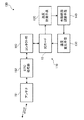
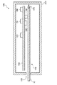
図1は、本発明の第1の実施の形態のETC車載器100の断面図であり、図2は、ETC車載器100の構成を示すブロック図である。
【0024】
ETC車載器100は、ICカード10を収容する記憶媒体収容手段110と、記憶媒体収容手段110に収容されたICカード10付近の温度を計測する温度計測手段120と、記憶媒体収容手段110に収容されたICカード10を冷却する温度変化手段130と、温度計測手段120によって計測された計測温度に応じて温度変化手段130の作動状態を調節する作動状態調節手段140とを備えている。
【0025】
筐体190に固定された回路基盤150には、温度計測手段120、作動状態調節手段140、路測機と無線通信するためのアンテナ151、ETCに関する処理を行うETC処理部152、およびICカード10との間で情報を送受信するコンタクト部160等が例えば図1に示すように配置されている。
【0026】
記憶媒体収容手段110は、筐体190に形成されたICカード挿入口193より挿入されるICカード10を着脱自在に収容するようになっている。記憶媒体収容手段110にICカード10が収容された際には、コンタクト部160を介してICカード10との間で情報が送受信されるようになっている。
【0027】
温度計測手段120は、記憶媒体収容手段110に収容されたICカード10付近、例えば、コンタクト部160近傍の回路基盤150上に配置される。温度計測手段120は、サーミスタや熱電対等の温度センサを有し、温度センサによって計測された計測温度を表す計測温度情報を作動状態調節手段140に出力するようになっている。
【0028】
温度変化手段130は、筐体190に固定されており、記憶媒体収容手段110に収容されたICカード10を冷却する冷却装置によって構成されている。本実施の形態において、温度変化手段130を構成する冷却装置は、筐体190に形成された吸気口191より吸気した空気をICカード10に向けて送風する冷却ファンを有している。
【0029】
なお、筐体190に吸気口191を形成する場合には、吸気口191には、防塵フィルタ192を設けることが望ましい。また、冷却ファンによって吸気された空気を排気するICカード挿入口193にも防塵フィルタを設ける場合には、ICカード10の挿入および排出を妨げないように十分な間隙を設けるようにする。
【0030】
温度計測手段120によって出力された計測温度情報は、作動状態調節手段140に入力されるようになっており、作動状態調節手段140は、入力された計測温度情報に応じて温度変化手段130の作動状態を調節するようになっている。
【0031】
具体的には、作動状態調節手段140は、予め定められた冷却温度を記憶しており、温度計測手段120によって出力された計測温度情報に示される計測温度が、温度変化手段130を構成する冷却ファンが停止しているときに冷却温度以上になった場合には、温度変化手段130を構成する冷却ファンを作動させ、冷却ファンが作動しているときに冷却温度未満になった場合には、冷却ファンを停止させるよう冷却ファンの駆動電源の供給を調整するようになっている。
【0032】
なお、作動状態調節手段140は、計測温度と冷却温度との差分温度に応じて冷却ファンの駆動電源の供給を調整するようにし、冷却ファンの回転速度および作動間欠時間の少なくとも一方を調整するようにしてもよい。
【0033】
また、作動状態調節手段140は、計測温度の時間推移に応じて冷却ファンの駆動電源の供給を調整するようにし、冷却ファンの回転速度および作動間欠時間の少なくとも一方を調整するようにしてもよい。
【0034】
また、作動状態調節手段140は、冷却ファンの作動および停止を単に切り替える場合には、計測温度が冷却温度以上か否かによって電流をオンオフするサーモスタットによって温度計測手段120と一体に構成してもよい。
【0035】
以下、図面を参照してETC車載器100の動作を説明する。
図3は、本発明の第1の実施の形態のETC車載器100の動作を示すフローチャートである。
【0036】
まず、記憶媒体収容手段110に収容されたICカード10付近の温度が温度計測手段120によって計測される(S110)。次に、温度計測手段120によって計測された計測温度が予め定められた冷却温度以上であるか否かが作動状態調節手段140によって判断される(S120)。
【0037】
計測温度が冷却温度以上と判断され、かつ温度変化手段130を構成する冷却ファンが停止している場合(S130)には、冷却ファンを作動させるよう冷却ファンの駆動電源の供給が作動状態調節手段140によって調節される(S140)。
【0038】
一方、計測温度が冷却温度未満と判断され、かつ冷却ファンが作動している場合(S150)には、冷却ファンを停止させるよう冷却ファンの駆動電源の供給が作動状態調節手段140によって調節される(S160)。
【0039】
以上説明したように、本発明の第1の実施の形態のETC車載器100は、記憶媒体収容手段110に収容されたICカード10付近の温度が所定の冷却温度以上になった場合には、温度変化手段130によってICカード10を冷却するため、収容されたICカード10の温度変化による変形や破壊を防止することができる。
【0040】
(第2の実施の形態)
図4は、本発明の第2の実施の形態のETC車載器200の断面図であり、図5は、ETC車載器200の構成を示すブロック図である。
【0041】
ETC車載器200は、ICカード10を収容する記憶媒体収容手段110と、記憶媒体収容手段110に収容されたICカード10付近の温度を計測する温度計測手段120と、記憶媒体収容手段110に収容されたICカード10を加熱する温度変化手段230と、温度計測手段120によって計測された計測温度に応じて温度変化手段230の作動状態を調節する作動状態調節手段240とを備えている。
【0042】
なお、本発明の第2の実施の形態に係るETC車載器200においては、本発明の第1の実施の形態に係るETC車載器100の構成要素と同一の構成要素に本発明の第1の実施の形態に係るETC車載器100の構成要素と同一の符号を付して、その説明を省略する。
【0043】
温度変化手段230は、筐体290に固定されており、記憶媒体収容手段110に収容されたICカード10を加熱する加熱装置によって構成されている。本実施の形態において、温度変化手段230を構成する加熱装置は、ICカード10に向けて熱を放射するヒータを有している。
【0044】
温度計測手段120によって出力された計測温度情報は、作動状態調節手段240に入力されるようになっており、作動状態調節手段240は、入力された計測温度情報に応じて温度変化手段230の作動状態を調節するようになっている。
【0045】
具体的には、作動状態調節手段240は、予め定められた加熱温度を記憶しており、温度計測手段120によって出力された計測温度情報に示される計測温度が、温度変化手段230を構成するヒータが停止しているときに加熱温度以下になった場合には、ヒータを作動させ、ヒータが作動しているときに加熱温度を超えた場合には、ヒータを停止させるようヒータの駆動電源の供給を調整するようになっている。
【0046】
なお、作動状態調節手段240は、計測温度と加熱温度との差分温度に応じてヒータの駆動電源の供給を調整するようにし、ヒータの加熱温度および加熱間欠時間の少なくとも一方を調整するようにしてもよい。
【0047】
また、作動状態調節手段240は、計測温度の時間推移に応じてヒータの駆動電源の供給を調整するようにし、ヒータの加熱温度および加熱間欠時間の少なくとも一方を調整するようにしてもよい。
【0048】
また、作動状態調節手段240は、ヒータの作動および停止を単に切り替える場合には、計測温度が加熱温度以下か否かによって電流をオンオフするサーモスタットによって温度計測手段120と一体に構成するようにしてもよい。
【0049】
以下、図面を参照してETC車載器200の動作を説明する。
図6は、本発明の第2の実施の形態のETC車載器200の動作を示すフローチャートである。
【0050】
まず、記憶媒体収容手段110に収容されたICカード10付近の温度が温度計測手段120によって計測される(S210)。次に、温度計測手段120によって計測された計測温度が予め定められた加熱温度以下であるか否かが作動状態調節手段240によって判断される(S220)。
【0051】
計測温度が加熱温度以下と判断され、かつ温度変化手段230を構成するヒータが停止している場合(S230)には、ヒータを作動させるようヒータの駆動電源の供給が作動状態調節手段240によって調節される(S240)。
【0052】
一方、計測温度が加熱温度を超えていると判断され、かつヒータが作動している場合(S250)には、ヒータを停止させるようヒータの駆動電源の供給が作動状態調節手段240によって調節される(S260)。
【0053】
以上説明したように、本発明の第2の実施の形態のETC車載器200は、記憶媒体収容手段110に収容されたICカード10付近の温度が所定の加熱温度以下になった場合には、温度変化手段230によってICカード10を加熱するため、収容されたICカード10の温度変化による変形や破壊を防止することができる。
【0054】
なお、本発明は、本発明の第1の実施の形態のETC車載器100と本発明の第2の実施の形態のETC車載器200を組み合わせることによって、ICカード10の過熱および過冷却による変形や破壊を防止することができる。以下に説明する、本発明の第3の実施の形態のETC車載器300は、ICカード10の過熱および過冷却による変形や破壊を防止するために冷却ファンおよびヒータに代えてペルチェ素子を用いるものである。
【0055】
(第3の実施の形態)
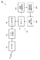
図7は、本発明の第3の実施の形態のETC車載器300の断面図であり、図8は、ETC車載器300の構成を示すブロック図である。
【0056】
ETC車載器300は、ICカード10を収容する記憶媒体収容手段110と、記憶媒体収容手段110に収容されたICカード10付近の温度を計測する温度計測手段120と、記憶媒体収容手段110に収容されたICカード10を冷却または加熱する温度変化手段330と、温度計測手段120によって計測された計測温度に応じて温度変化手段330の作動状態を調節する作動状態調節手段340とを備えている。
【0057】
なお、本発明の第3の実施の形態に係るETC車載器300においては、本発明の第2の実施の形態に係るETC車載器200の構成要素と同一の構成要素に本発明の第2の実施の形態に係るETC車載器200の構成要素と同一の符号を付して、その説明を省略する。
【0058】
温度変化手段330は、筐体290に固定されており、記憶媒体収容手段110に収容されたICカード10を冷却および加熱するペルチェ素子によって構成されている。
【0059】
温度計測手段120によって出力された計測温度情報は、作動状態調節手段340に入力されるようになっており、作動状態調節手段340は、入力された計測温度情報に応じて温度変化手段330の作動状態を調節するようになっている。
【0060】
具体的には、作動状態調節手段340は、予め定められた冷却温度および加熱温度を記憶しており、温度計測手段120によって出力された計測温度情報に示される計測温度が、温度変化手段330を構成するペルチェ素子が停止しているときに冷却温度以上または加熱温度以下になった場合には、ペルチェ素子を作動させ、ペルチェ素子が作動しているときに計測温度が冷却温度未満から加熱温度を超える範囲になった場合には、ペルチェ素子を停止させるようペルチェ素子の通電を調整するようになっている。
【0061】
ここで、作動状態調節手段340は、計測温度が冷却温度以上になった場合と計測温度が加熱温度以下になった場合とにおいてに正負逆の電流がペルチェ素子に流れるよう通電を調整するようになっている。なお、ペルチェ素子において、記憶媒体収容手段110に収容されたICカード10側の面を冷却する電流の方向を正方向、加熱する電流の方向を逆方向とする。
【0062】
なお、作動状態調節手段340は、計測温度と冷却温度または加熱温度との差分温度に応じてペルチェ素子の通電を調整するようにし、ペルチェ素子に流す電流または電圧、および通電間欠時間の少なくとも1つを調整するようにしてもよい。
【0063】
また、作動状態調節手段340は、計測温度の時間推移に応じてペルチェ素子の通電を調整するようにし、ペルチェ素子に流す電流または電圧、および通電間欠時間の少なくとも1つを調整するようにしてもよい。
【0064】
また、作動状態調節手段340は、ペルチェ素子の作動および停止を単に切り替える場合には、計測温度が冷却温度以上か否かによって電流をオンオフするサーモスタットと計測温度が加熱温度以上か否かによって電流をオンオフするサーモスタットとによって温度計測手段120と一体に構成するようにしてもよい。
【0065】
以下、図面を参照してETC車載器300の動作を説明する。
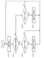
図9は、本発明の第3の実施の形態のETC車載器300の動作を示すフローチャートである。
【0066】
まず、記憶媒体収容手段110に収容されたICカード10付近の温度が温度計測手段120によって計測される(S310)。次に、温度計測手段120によって計測された計測温度が予め定められた冷却温度以上であるか否かが作動状態調節手段340によって判断される(S320)。
【0067】
計測温度が冷却温度以上と判断され、かつ温度変化手段330を構成するペルチェ素子の通電が正方向ではない場合(S330)には、ペルチェ素子に正方向の電流が流れるようペルチェ素子の通電が作動状態調節手段340によって調節される(S340)。
【0068】
一方、計測温度が加熱温度を超えていると判断された場合には、温度計測手段120によって計測された計測温度が予め定められた加熱温度以下であるか否かが作動状態調節手段340によって判断される(S350)。
【0069】
計測温度が加熱温度以下と判断され、かつペルチェ素子の通電が逆方向ではない場合(S360)には、ペルチェ素子に逆方向の電流が流れるようペルチェ素子の通電が作動状態調節手段340によって調節される(S370)。一方、計測温度が加熱温度を超えていると判断され、かつペルチェ素子への通電が停止していない場合(S380)には、ペルチェ素子の通電が停止するよう作動状態調節手段340によって調節される(S390)。
【0070】
以上説明したように、本発明の第3の実施の形態のETC車載器300は、記憶媒体収容手段110に収容されたICカード10付近の温度が所定の冷却温度以上または加熱温度以下になった場合には、温度変化手段330によってICカード10を冷却または加熱するため、収容されたICカード10の熱による変形や破壊を防止することができる。
【0071】
なお、本発明は、ICカード10の冷却または加熱のいずれか一方の効果を得るために、作動状態調節手段340の構成を簡略化してもよい。作動状態調節手段340の構成を簡略化した場合については、本発明の第3の実施の形態の説明に基づいて容易に実施できるため、その説明を省略する。
【0072】
(第4の実施の形態)
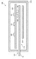
図10は、本発明の第4の実施の形態のETC車載器400の断面図であり、図11は、ETC車載器400の構成を示すブロック図である。
【0073】
ETC車載器400は、ICカード10を収容する記憶媒体収容手段110と、記憶媒体収容手段110に収容されたICカード10付近の温度を計測する温度計測手段120と、記憶媒体収容手段110に収容されたICカード10を排出する媒体排出手段470と、温度計測手段120によって計測された計測温度に応じて媒体排出手段470を作動させる排出作動手段480とを備えている。
【0074】
なお、本発明の第4の実施の形態に係るETC車載器400においては、本発明の第2の実施の形態に係るETC車載器200の構成要素と同一の構成要素に本発明の第2の実施の形態に係るETC車載器200の構成要素と同一の符号を付して、その説明を省略する。
【0075】
媒体排出手段470は、記憶媒体収容手段110にICカード10が収容された際にICカード10の端部と当接する当接部と、一端を当接部に固定され、他端を筐体290に固定された1つ以上のバネ等による弾性体によって構成され、当接部がICカード10の挿入方向に変移するようになっている。
【0076】
媒体排出手段470は、記憶媒体収容手段110に収容されたICカード10がコンタクト部160と情報の送受信が可能となる位置でICカード10をラッチするようになっている。このラッチは、排出作動手段480によって解除可能になっており、ラッチが解除された際にICカード10は、弾性体の反発力を以って筐体290から排出されるようになっている。
【0077】
温度計測手段120によって出力された計測温度情報は、排出作動手段480に入力されるようになっており、排出作動手段480は、入力された計測温度情報に応じて媒体排出手段470を作動させるようになっている。
【0078】
具体的には、排出作動手段480は、予め定められた許容温度範囲を記憶しており、温度計測手段120によって出力された計測温度情報に示される計測温度が、許容温度範囲外に達した場合には、媒体排出手段470のラッチを解除するようになっている。
【0079】
以下、図面を参照してETC車載器400の動作を説明する。
図12は、本発明の第4の実施の形態のETC車載器400の動作を示すフローチャートである。
【0080】
まず、記憶媒体収容手段110に収容されたICカード10付近の温度が温度計測手段120によって計測される(S410)。次に、温度計測手段120によって計測された計測温度が予め定められた許容温度範囲外に達したか否かが排出作動手段480によって判断される(S420)。
【0081】
計測温度が許容温度範囲外に達したと判断された場合には、媒体排出手段470が排出作動手段480によって作動され(S430)、記憶媒体収容手段110に収容されたICカード10が媒体排出手段470によって筐体290から排出される(S440)。
【0082】
以上説明したように、本発明の第4の実施の形態のETC車載器400は、記憶媒体収容手段110に収容されたICカード10付近の温度が所定の許容温度範囲外に達した場合には、媒体排出手段470によってICカード10を排出するため、収容されたICカード10の温度変化による変形や破壊を防止することができる。
【0083】
なお、本発明は、ICカード10の冷却または加熱のいずれか一方の効果を得るために、排出作動手段480の構成を簡略化してもよい。排出作動手段480の構成を簡略化した場合については、本発明の第4の実施の形態の説明に基づいて容易に実施できるため、その説明を省略する。
【0084】
また、本発明は、本発明の第4の実施の形態のETC車載器400と本発明の第1の実施の形態のETC車載器100乃至本発明の第3の実施の形態のETC車載器300の何れかとを単に組み合わせることによって、ICカード10の温度変化による変形や破壊をより防止することができる。
【0085】
【発明の効果】
以上説明したように、本発明は、収容された記録媒体の温度変化による変形や破壊を防止することができる自動料金収受車載器を提供することができるものである。
【図面の簡単な説明】
【図1】本発明の第1の実施の形態のETC車載器の断面図
【図2】本発明の第1の実施の形態のETC車載器の構成を示すブロック図
【図3】本発明の第1の実施の形態のETC車載器の動作を示すフローチャート
【図4】本発明の第2の実施の形態のETC車載器の断面図
【図5】本発明の第2の実施の形態のETC車載器の構成を示すブロック図
【図6】本発明の第2の実施の形態のETC車載器の動作を示すフローチャート
【図7】本発明の第3の実施の形態のETC車載器の断面図
【図8】本発明の第3の実施の形態のETC車載器の構成を示すブロック図
【図9】本発明の第3の実施の形態のETC車載器の動作を示すフローチャート
【図10】本発明の第4の実施の形態のETC車載器の断面図
【図11】本発明の第4の実施の形態のETC車載器の構成を示すブロック図
【図12】本発明の第4の実施の形態のETC車載器の動作を示すフローチャート
【図13】従来のDSRC車載器の断面図
【符号の説明】
10 ICカード
100、200、300、400 ETC車載器
110 記憶媒体収容手段
120 温度計測手段
130、230、330 温度変化手段
140、240、340 作動状態調節手段
150 回路基盤
151 アンテナ
152 ETC処理部
160、920 コンタクト部
190、290 筐体
191 吸気口
192 防塵フィルタ
193 ICカード挿入口
470 媒体排出手段
480 排出作動手段
900 DSRC車載器
910 ICカード収納部
930 回路基板
940、950 温度センサ
960、970 警報手段[0001]
BACKGROUND OF THE INVENTION
The present invention relates to an automatic toll collection vehicle-mounted device, and more specifically, an ETC on-vehicle vehicle that constitutes an automatic toll collection system (Electronic Toll Collection System, also referred to as “ETC”) that collects toll collection on a toll road such as an expressway by wireless communication. It is about a vessel.
[0002]
[Prior art]
2. Description of the Related Art Conventionally, an automatic toll collection vehicle-mounted device that collects tolls on a toll road such as an expressway by wireless communication is known (see, for example, Patent Document 1).
[0003]
A DSRC vehicle-mounted device (automatic toll collection vehicle-mounted device) 900 disclosed in Patent Document 1 shown in FIG. 13 performs narrow-area communication (also referred to as Dedicated Short Range Communications, “DSRC”) employed in ETC. . The DSRC vehicle-mounted
[0004]
In the DSRC in-
[0005]
[Patent Document 1]
JP 2000-276625 A (5th page, Fig. 1-2)
[0006]
[Problems to be solved by the invention]
However, such a conventional DSRC in-
[0007]
The present invention has been made to solve such a problem, and provides an automatic toll collecting vehicle-mounted device that can prevent deformation and destruction of a stored recording medium due to a temperature change.
[0008]
[Means for Solving the Problems]
The automatic toll collecting vehicle-mounted device of the present invention is stored in a storage medium storage unit that stores a storage medium, a temperature measurement unit that measures the temperature in the vicinity of the storage medium stored in the storage medium storage unit, and the storage medium storage unit. A temperature change means for changing the temperature of the storage medium, and an operation state adjustment means for adjusting the operation state of the temperature change means according to the measured temperature measured by the temperature measurement means. Yes.
With this configuration, since the temperature of the recording medium is changed by the temperature changing means according to the temperature in the vicinity of the recording medium accommodated in the storage medium accommodating means, it is possible to prevent deformation and destruction due to the temperature change of the accommodated recording medium. Can do.
[0009]
In the automatic toll collecting vehicle-mounted device according to the present invention, the temperature changing unit includes a cooling device that cools the storage medium stored in the storage medium storage unit.
With this configuration, since the storage medium is cooled by the temperature changing unit in accordance with the temperature in the vicinity of the storage medium stored in the storage medium storage unit, it is possible to prevent deformation and destruction due to the temperature change of the stored storage medium. .
[0010]
Moreover, the automatic toll collection vehicle-mounted device of the present invention has a cooling fan that blows air toward the storage medium stored in the storage medium storage means by the cooling device.
With this configuration, the storage medium is cooled by the cooling fan in accordance with the temperature in the vicinity of the storage medium accommodated in the storage medium accommodation means, so that deformation or destruction due to a temperature change of the accommodated storage medium can be prevented.
[0011]
In addition, the automatic toll collecting vehicle-mounted device of the present invention operates the temperature changing unit when the adjustment of the operation state by the operation state adjustment unit is equal to or higher than a predetermined cooling temperature, When the measured temperature becomes lower than the cooling temperature, the temperature changing unit is stopped.
With this configuration, when the temperature in the vicinity of the storage medium stored in the storage medium storage unit becomes equal to or higher than a predetermined cooling temperature, the storage medium is cooled by the temperature change unit. Deformation and destruction can be prevented.
[0012]
Moreover, the automatic toll collecting vehicle-mounted device of the present invention has a configuration in which the temperature changing means is a heating device that heats the storage medium accommodated in the storage medium accommodation means.
With this configuration, since the storage medium is heated by the temperature changing unit in accordance with the temperature in the vicinity of the storage medium stored in the storage medium storage unit, it is possible to prevent deformation and destruction due to the temperature change of the stored storage medium. .
[0013]
In the automatic toll collecting vehicle-mounted device of the present invention, the heating device has a heater that radiates heat toward the storage medium stored in the storage medium storage means.
With this configuration, since the storage medium is heated by the heater in accordance with the temperature in the vicinity of the storage medium stored in the storage medium storage means, it is possible to prevent deformation and destruction due to a temperature change of the stored storage medium.
[0014]
Further, the automatic toll collecting vehicle-mounted device of the present invention operates the temperature changing means when the adjustment of the operating state by the operating state adjusting means is less than or equal to a predetermined heating temperature, When the measured temperature exceeds the heating temperature, the temperature changing means is configured to stop.
With this configuration, when the temperature in the vicinity of the storage medium accommodated in the storage medium accommodation means becomes equal to or lower than a predetermined heating temperature, the storage medium is heated by the temperature change means, so that the temperature change of the accommodated recording medium Deformation and destruction can be prevented.
[0015]
In the automatic toll collecting vehicle-mounted device of the present invention, the temperature changing means has a Peltier element.
With this configuration, since the storage medium is cooled or heated by the Peltier element in accordance with the temperature in the vicinity of the storage medium stored in the storage medium storage means, it is possible to prevent deformation and destruction due to a temperature change of the stored storage medium. it can.
[0016]
The automatic toll collecting vehicle-mounted device of the present invention is housed in the storage medium housing means when the operation state adjustment by the operation state adjustment means is performed when the measured temperature is equal to or higher than a predetermined cooling temperature. The Peltier element is operated so as to absorb heat from the surface on the storage medium side, and when the measured temperature becomes lower than the cooling temperature, the Peltier element is stopped.
With this configuration, when the temperature in the vicinity of the storage medium stored in the storage medium storage means exceeds a predetermined cooling temperature, the storage medium is cooled by the Peltier element. And destruction can be prevented.
[0017]
The automatic toll collecting vehicle-mounted device of the present invention is accommodated in the storage medium accommodating means when the adjustment of the operation state by the operation state adjusting means is less than a predetermined heating temperature. The Peltier element is operated to dissipate heat from the surface on the storage medium side, and the Peltier element is stopped when the measured temperature exceeds the cooling temperature.
With this configuration, when the temperature in the vicinity of the storage medium stored in the storage medium storage means becomes equal to or lower than the predetermined heating temperature, the storage medium is heated by the Peltier element. And destruction can be prevented.
[0018]
Further, the automatic toll collecting vehicle-mounted device of the present invention includes a storage medium storage unit that stores a storage medium, a temperature measurement unit that measures a temperature in the vicinity of the storage medium stored in the storage medium storage unit, and the storage medium storage unit A medium discharge means for discharging the storage medium stored in the storage medium, and a discharge operation means for operating the medium discharge means in accordance with the measured temperature measured by the temperature measurement means.
With this configuration, since the recording medium is ejected by the medium ejecting means in accordance with the temperature in the vicinity of the storage medium accommodated in the storage medium accommodating means, it is possible to prevent deformation and destruction due to a temperature change of the accommodated recording medium. .
[0019]
The automatic toll collecting vehicle-mounted device of the present invention operates a medium discharge means for discharging the storage medium stored in the storage medium storage means, and the medium discharge means according to the measured temperature measured by the temperature measurement means. And a discharge operating means.
With this configuration, since the recording medium is ejected by the medium ejecting means in accordance with the temperature in the vicinity of the storage medium accommodated in the storage medium accommodating means, deformation or destruction due to temperature change of the accommodated recording medium is prevented by cooling or heating. If it is not possible, you can deal with it.
[0020]
Moreover, the automatic toll collecting vehicle-mounted device of the present invention has a configuration in which the operation of the medium discharge means by the discharge operation means is performed when the measured temperature reaches outside a predetermined allowable temperature range. .
With this configuration, when the temperature in the vicinity of the storage medium stored in the storage medium storage means reaches a predetermined allowable temperature range, the recording medium is discharged by the medium discharge means. Can prevent deformation and destruction.
[0021]
Moreover, the automatic toll collection vehicle-mounted device of the present invention has a configuration in which the medium discharge means has an elastic body, and the storage medium is discharged by the medium discharge means by the repulsive force of the elastic body. Yes.
With this configuration, when the temperature in the vicinity of the storage medium stored in the storage medium storage means reaches outside the predetermined allowable temperature range, the recording medium is discharged by the repulsive force of the elastic body. Deformation and destruction due to temperature change can be prevented.
[0022]
DETAILED DESCRIPTION OF THE INVENTION
Embodiments of the present invention will be described below with reference to the drawings. The embodiment of the present invention described below shows an example in which the automatic toll collecting in-vehicle device of the present invention is applied to an ETC on-vehicle device, and an IC card is applied as a recording medium accommodated in the ETC on-vehicle device. .
[0023]
(First embodiment)
FIG. 1 is a cross-sectional view of the ETC on-
[0024]
The ETC vehicle-mounted
[0025]
The
[0026]
The storage medium accommodating means 110 is configured to detachably accommodate the
[0027]
The
[0028]
The temperature changing means 130 is fixed to the
[0029]
In the case where the
[0030]
The measured temperature information output by the
[0031]
Specifically, the operating
[0032]
The operating
[0033]
Further, the operating
[0034]
In addition, the operating
[0035]
Hereinafter, the operation of the ETC vehicle-mounted
FIG. 3 is a flowchart showing the operation of the ETC on-
[0036]
First, the temperature near the
[0037]
When the measured temperature is determined to be equal to or higher than the cooling temperature and the cooling fan constituting the
[0038]
On the other hand, when it is determined that the measured temperature is lower than the cooling temperature and the cooling fan is operating (S150), the operation
[0039]
As described above, the ETC in-
[0040]
(Second Embodiment)
FIG. 4 is a cross-sectional view of the ETC vehicle-mounted
[0041]
The ETC vehicle-mounted
[0042]
In addition, in the ETC
[0043]
The
[0044]
The measured temperature information output by the
[0045]
Specifically, the operating
[0046]
The operating state adjusting means 240 adjusts the supply of the heater drive power according to the difference temperature between the measured temperature and the heating temperature, and adjusts at least one of the heater heating temperature and the heating intermittent time. Also good.
[0047]
Further, the operating state adjusting means 240 may adjust the supply of the driving power of the heater according to the time transition of the measured temperature, and may adjust at least one of the heating temperature of the heater and the intermittent heating time.
[0048]
In addition, the operating
[0049]
Hereinafter, the operation of the ETC vehicle-mounted
FIG. 6 is a flowchart showing the operation of the ETC on-
[0050]
First, the temperature measuring means 120 measures the temperature near the
[0051]
When it is determined that the measured temperature is equal to or lower than the heating temperature, and the heater that constitutes the
[0052]
On the other hand, when it is determined that the measured temperature exceeds the heating temperature and the heater is operating (S250), the operating state adjusting means 240 adjusts the supply of the heater drive power to stop the heater. (S260).
[0053]
As described above, the ETC in-
[0054]
In the present invention, the ETC on-
[0055]
(Third embodiment)
FIG. 7 is a cross-sectional view of the ETC vehicle-mounted
[0056]
The ETC vehicle-mounted
[0057]
In addition, in the ETC
[0058]
The temperature changing means 330 is fixed to the
[0059]
The measured temperature information output by the
[0060]
Specifically, the operating
[0061]
Here, the operating state adjusting means 340 adjusts the energization so that positive and negative currents flow through the Peltier element when the measured temperature is equal to or higher than the cooling temperature and when the measured temperature is equal to or lower than the heating temperature. It has become. In the Peltier element, the direction of the current for cooling the surface on the side of the
[0062]
The operating state adjusting means 340 adjusts the energization of the Peltier element according to the difference temperature between the measured temperature and the cooling temperature or the heating temperature, and at least one of the current or voltage flowing through the Peltier element and the energization intermittent time. May be adjusted.
[0063]
Further, the operating state adjusting means 340 adjusts the energization of the Peltier element according to the time transition of the measured temperature, and adjusts at least one of the current or voltage flowing through the Peltier element and the energization intermittent time. Good.
[0064]
Further, when the operation state adjusting means 340 simply switches between the operation and stop of the Peltier element, the operation state adjusting means 340 changes the current depending on whether the measured temperature is equal to or higher than the cooling temperature and whether the measured temperature is equal to or higher than the heating temperature. You may make it comprise integrally with the temperature measurement means 120 by the thermostat to turn on and off.
[0065]
Hereinafter, the operation of the ETC vehicle-mounted
FIG. 9 is a flowchart illustrating an operation of the ETC on-
[0066]
First, the temperature near the
[0067]
When it is determined that the measured temperature is equal to or higher than the cooling temperature and the energization of the Peltier element constituting the temperature changing means 330 is not in the positive direction (S330), the energization of the Peltier element is activated so that a positive current flows in the Peltier element. It is adjusted by the state adjusting means 340 (S340).
[0068]
On the other hand, when it is determined that the measured temperature exceeds the heating temperature, the operating
[0069]
If it is determined that the measured temperature is equal to or lower than the heating temperature and the energization of the Peltier element is not in the reverse direction (S360), the energization of the Peltier element is adjusted by the operating state adjusting means 340 so that the reverse current flows in the Peltier element. (S370). On the other hand, when it is determined that the measured temperature exceeds the heating temperature and energization to the Peltier element is not stopped (S380), the operating
[0070]
As described above, in the ETC in-
[0071]
In the present invention, in order to obtain either effect of cooling or heating of the
[0072]
(Fourth embodiment)
FIG. 10 is a cross-sectional view of the ETC vehicle-mounted
[0073]
The ETC vehicle-mounted
[0074]
In addition, in the ETC
[0075]
The medium discharge means 470 is fixed to the contact portion that contacts the end portion of the
[0076]
The medium ejecting means 470 latches the
[0077]
The measured temperature information output by the
[0078]
Specifically, the
[0079]
Hereinafter, the operation of the ETC vehicle-mounted
FIG. 12 is a flowchart showing the operation of the ETC vehicle-mounted
[0080]
First, the temperature measuring means 120 measures the temperature near the
[0081]
If it is determined that the measured temperature has exceeded the allowable temperature range, the medium discharge means 470 is operated by the discharge operation means 480 (S430), and the
[0082]
As described above, the ETC vehicle-mounted
[0083]
In the present invention, the configuration of the discharge operation means 480 may be simplified in order to obtain either effect of cooling or heating the
[0084]
The present invention also relates to the ETC on-
[0085]
【The invention's effect】
As described above, the present invention can provide an automatic toll collecting vehicle-mounted device that can prevent deformation and destruction due to temperature change of a stored recording medium.
[Brief description of the drawings]
FIG. 1 is a cross-sectional view of an ETC vehicle-mounted device according to a first embodiment of the present invention.
FIG. 2 is a block diagram showing a configuration of the ETC on-vehicle device according to the first embodiment of this invention.
FIG. 3 is a flowchart showing the operation of the ETC on-vehicle device according to the first embodiment of this invention.
FIG. 4 is a cross-sectional view of an ETC vehicle-mounted device according to a second embodiment of the present invention.
FIG. 5 is a block diagram showing a configuration of an ETC on-vehicle device according to a second embodiment of the present invention.
FIG. 6 is a flowchart showing the operation of the ETC on-vehicle device according to the second embodiment of this invention.
FIG. 7 is a sectional view of an ETC vehicle-mounted device according to a third embodiment of the present invention.
FIG. 8 is a block diagram showing a configuration of an ETC on-vehicle device according to a third embodiment of the present invention.
FIG. 9 is a flowchart showing the operation of the on-board ETC device according to the third embodiment of the present invention.
FIG. 10 is a sectional view of an ETC vehicle-mounted device according to a fourth embodiment of the present invention.
FIG. 11 is a block diagram showing a configuration of an ETC on-vehicle device according to a fourth embodiment of the present invention.
FIG. 12 is a flowchart showing the operation of the ETC on-vehicle device according to the fourth embodiment of the present invention.
FIG. 13 is a sectional view of a conventional DSRC OBE
[Explanation of symbols]
10 IC card
100, 200, 300, 400 ETC OBE
110 Storage medium accommodation means
120 Temperature measurement means
130, 230, 330 Temperature changing means
140, 240, 340 Operating state adjusting means
150 circuit board
151 Antenna
152 ETC processing part
160, 920 Contact part
190,290 housing
191 Air intake
192 Dustproof filter
193 IC card slot
470 Medium discharge means
480 Discharge actuation means
900 DSRC OBE
910 IC card compartment
930 circuit board
940, 950 Temperature sensor
960, 970 Alarm means
Claims (14)
前記記憶媒体収容手段に収容された記憶媒体付近の温度を計測する温度計測手段と、
前記記憶媒体収容手段に収容された記憶媒体の温度を変化させる温度変化手段と、
前記温度計測手段によって計測された計測温度に応じて前記温度変化手段の作動状態を調節する作動状態調節手段とを備えたことを特徴とする自動料金収受車載器。Storage medium storage means for storing the storage medium;
Temperature measuring means for measuring the temperature in the vicinity of the storage medium stored in the storage medium storing means;
Temperature changing means for changing the temperature of the storage medium accommodated in the storage medium accommodating means;
An automatic toll collecting vehicle-mounted device comprising: an operating state adjusting unit that adjusts an operating state of the temperature changing unit in accordance with a measured temperature measured by the temperature measuring unit.
前記記憶媒体収容手段に収容された記憶媒体付近の温度を計測する温度計測手段と、
前記記憶媒体収容手段に収容された記憶媒体を排出する媒体排出手段と、
前記温度計測手段によって計測された計測温度に応じて前記媒体排出手段を作動させる排出作動手段とを備えたことを特徴とする自動料金収受車載器。Storage medium storage means for storing the storage medium;
Temperature measuring means for measuring the temperature in the vicinity of the storage medium stored in the storage medium storing means;
Medium discharge means for discharging the storage medium stored in the storage medium storage means;
An automatic toll collecting vehicle-mounted device comprising: a discharge operation unit that operates the medium discharge unit according to the measured temperature measured by the temperature measurement unit.
前記温度計測手段によって計測された計測温度に応じて前記媒体排出手段を作動させる排出作動手段とを備えたことを特徴とする請求項1乃至請求項10の何れかに記載の自動料金収受車載器。Medium discharge means for discharging the storage medium stored in the storage medium storage means;
11. The automatic toll collecting vehicle-mounted device according to claim 1, further comprising a discharge operation unit that operates the medium discharge unit in accordance with a measured temperature measured by the temperature measurement unit. .
Priority Applications (1)
| Application Number | Priority Date | Filing Date | Title |
|---|---|---|---|
| JP2003181296A JP2005018355A (en) | 2003-06-25 | 2003-06-25 | Onboard electronic toll collection unit |
Applications Claiming Priority (1)
| Application Number | Priority Date | Filing Date | Title |
|---|---|---|---|
| JP2003181296A JP2005018355A (en) | 2003-06-25 | 2003-06-25 | Onboard electronic toll collection unit |
Publications (1)
| Publication Number | Publication Date |
|---|---|
| JP2005018355A true JP2005018355A (en) | 2005-01-20 |
Family
ID=34182047
Family Applications (1)
| Application Number | Title | Priority Date | Filing Date |
|---|---|---|---|
| JP2003181296A Pending JP2005018355A (en) | 2003-06-25 | 2003-06-25 | Onboard electronic toll collection unit |
Country Status (1)
| Country | Link |
|---|---|
| JP (1) | JP2005018355A (en) |
Cited By (2)
| Publication number | Priority date | Publication date | Assignee | Title |
|---|---|---|---|---|
| JP2008121988A (en) * | 2006-11-13 | 2008-05-29 | Toshiba Corp | Cooker |
| JP2015529964A (en) * | 2013-04-22 | 2015-10-08 | ▲華▼▲為▼▲終▼端有限公司 | Device for preventing deformation of communication card |
-
2003
- 2003-06-25 JP JP2003181296A patent/JP2005018355A/en active Pending
Cited By (2)
| Publication number | Priority date | Publication date | Assignee | Title |
|---|---|---|---|---|
| JP2008121988A (en) * | 2006-11-13 | 2008-05-29 | Toshiba Corp | Cooker |
| JP2015529964A (en) * | 2013-04-22 | 2015-10-08 | ▲華▼▲為▼▲終▼端有限公司 | Device for preventing deformation of communication card |
Similar Documents
| Publication | Publication Date | Title |
|---|---|---|
| JP4513816B2 (en) | Temperature control mechanism and vehicle | |
| TWI221811B (en) | Thermal inkjet printer having enhanced heat removal capability and method of assembling the printer | |
| JP6210105B2 (en) | Battery device | |
| JP2009511361A (en) | Selectable controllable heating and cleaning system | |
| WO2000059034A1 (en) | A cooling unit for an integrated circuit package | |
| KR20060101671A (en) | Secondary battery module | |
| JP2004502144A5 (en) | ||
| US11577695B2 (en) | Movable body | |
| KR101647912B1 (en) | Device for electrically heating fluid for a motor vehicle, and related heating and/or air-conditioning apparatus | |
| JP2008011233A (en) | Photographic apparatus | |
| US20200094782A1 (en) | Imaging system | |
| CN110166737B (en) | Vehicle exterior monitoring device | |
| JP2013528765A (en) | Electric heating device and corresponding heater | |
| CN101305857B (en) | Drying system for a hair removing device | |
| JP2005018355A (en) | Onboard electronic toll collection unit | |
| US11509800B2 (en) | On-board camera device | |
| US7775708B2 (en) | Device for thermal coupling | |
| EP1052757A2 (en) | Charge control apparatus for a battery pack | |
| JP2007109536A (en) | Temperature detection device | |
| EP0988981A2 (en) | A method and apparatus for erasing printed data from a rewritable card | |
| EP3952055A1 (en) | Vehicle provided with a wireless charger for mobile phones | |
| JP3228076B2 (en) | Automotive electronics | |
| CA2201049A1 (en) | Auxiliary electrical heater for heating the interior of a motor vehicle | |
| ES2787127T3 (en) | Management procedure of a thermal printer, device and corresponding program | |
| US20170187906A1 (en) | Image pickup apparatus with forced air-cooling structure |