【0001】
【発明の属する技術分野】
本発明は、複写機、プリンタ、ファクシミリ等の画像形成装置、詳しくは中間転写体を備えた画像形成装置に関するものである。
【0002】
【従来の技術】
従来における中間転写型の画像形成装置として、例えば特許文献1から、静電潜像に応じたトナー像を形成載置する感光体ドラムと、この感光体ドラム上のトナー像を中間的に転写する中間転写ベルトと、この中間転写ベルトに対して感光体ドラム上のトナー像を転写させる一次転写装置と、中間転写ベルト上に転写されたトナー像を用紙に一括して二次転写させる二次転写装置とを備えた構成のものが知られている。
【特許文献1】
特開平5−323704号公報
【0003】
上記中間転写ベルトは多層構造となっており、ベース層を例えば伸びの少ないフッ素樹脂やPVDシート、ポリイミド系樹脂でつくり、表面をフッ素系樹脂等の平滑性のよいコート層で被って成っている。
【0004】
この中間転写ベルトを安定走行させるために従来からベルト端部に付けられたガイド部材をローラ片側端部にベルト寄り力により接触させ、回転させることが行われている。ベルトに外乱が生じない様な装置では、ベルトは寄り力によって一方向に寄って安定走行することが可能である。しかしながら、ベルトに外部からクリーニングブラシや転写ローラといった一定速度で回転する部材が接離する装置においては、回転部材の接触によってベルトの寄りが乱される現象が発生している。
【0005】
ベルトの寄りが乱れると、中間転写ベルト上に重ね合わされる画像位置がずれ、画像ズレが発生し、さらにひどい場合には、ベルトのローラへの乗り上げが発生する。
【0006】
回転する部材の接触によってベルトの寄りが乱されないようにするためには、回転部材の回転軸とベルトを張架したローラとの平行度が高精度に保たれていることが重要であり、従来は個々の部品精度によって平行度を出してベルトの乗り上げといった問題を防止してきた。
【0007】
【発明が解決しようとする課題】
しかし、近年の高画質化要求から画像解像度が上がり、僅かな外乱によって生じる微小な画像位置ズレも無視できないようになってきている。回転部材の当接によって僅かな外乱も生じさせない様にするためには、部品精度向上では限界がある。特に、機械の構造上もしくはメンテナンス性から中間転写ユニットと外部から接触する回転部材は別のユニットになることが多く、無調整で相互の平行度を出すことは困難である。
【0008】
そこで本発明は、例えば中間転写ベルトが掛け回されたローラ部材と外部から接触する回転駆動部材の回転軸の平行度を調整することにより、回転駆動部材の接触によってもベルト寄りに影響を与えず、画像ズレが無い良好な画像を得ることを課題とするものである。
【0009】
【課題を解決するための手段】
上記課題は、本発明により、少なくとも2本のローラにて張架される無端状のベルト部材と、該ベルト部材を駆動する駆動手段と、上記ベルト部材に接離する回転駆動部材を具備する画像形成装置において、上記回転駆動部材の回転軸と無端状ベルト部材を張架するローラとの平行度を調整可能としたことにより解決される。
【0010】
上記回転駆動部材のベルト部材への接触時の、離間時に対するベルト部材変位方向を検出可能な手段を有していれば、好適である。検出されたベルト部材の変位方向情報に基づき、回転駆動部材の回転軸と無端状ベルト部材を張架するローラ部材との平行度を自動的に調整できれば、一層効果的である。
【0011】
【発明の実施の形態】
以下、本発明を図示の例に基づいて詳細に説明する。
図1は、本発明の一例を示すもので、タンデム型間接転写方式の電子写真装置である。図中符号100は複写装置本体、200はそれを載せる給紙テーブル、300は複写装置本体100上に取り付けるスキャナ、400はさらにその上に取り付ける原稿自動搬送装置(ADF)である。
【0012】
複写装置本体100には、中央に、無端ベルト状の中間転写体10が設けられる。中間転写体10は、ベース層を例えば伸びの少ないフッ素樹脂としたり、伸びの大きなゴム材料に帆布など伸びにくい材料を組み合わせて構成して、その上に弾性層を設ける。弾性層は、例えばフッ素系ゴムやアクリロニトリル−ブタジエン共重合ゴムなどでつくる。その弾性層の表面は、例えばフッ素系樹脂をコーティングして平滑性のよいコート層で被われる。
【0013】
そして、図示例では中間転写体10を3つの支持ローラ14、15、16に掛け回して図中時計回りに回転搬送可能とする。この例では、3つのなかで第2の支持ローラ15の左側に、画像転写後に中間転写体10上に残留する残留トナーを除去する中間転写体クリーニング装置17を設けている。また3つのローラ中、第1の支持ローラ14と第2の支持ローラ15間に張り渡した中間転写体10上には、その搬送方向に沿って、ブラック・イエロー・マゼンタ・シアンの4つの画像形成手段18を横に並べて配置してタンデム画像形成装置20を構成している。そのタンデム画像形成装置20の上には、さらに露光装置21を設けている。
【0014】
一方、中間転写体10を挟んでタンデム画像形成装置20と反対の側には、2次転写装置22を備えている。2次転写装置22は、図示例では、2つのローラ23間に、無端ベルトである2次転写ベルト24を掛け渡し、中間転写体10を介して第3の支持ローラ16に押し当てて配置され、中間転写体10上の画像をシートに転写する。この2次転写装置としては、2次転写ローラを用いるものがよく知られている。2次転写装置22は、画像転写後のシートをこの定着装置25へと搬送するシート搬送機能も備えている。もちろん、2次転写装置22として、転写ローラを用いるものもあり(図2)、非接触のチャージャを配置する場合もあるが、それらの場合は、このシート搬送機能を併せ備えることは難しくなる。
【0015】
2次転写装置22の横には、シート上の転写画像を定着する定着装置25を設けている。定着装置25は、無端ベルトである定着ベルト26に加圧ローラ27を押し当てて構成されている。
【0016】
なお、図示例では、このような2次転写装置22および定着装置25の下に、上述したタンデム画像形成装置20と平行に、シートの両面に画像を記録すべくシートを反転するシート反転装置28も備えている。
【0017】
このカラー電子写真装置を用いてコピーをとる場合について説明する。まず原稿自動搬送装置400の原稿台30上に原稿をセットする。あるいは、原稿自動搬送装置400を開いてスキャナ300のコンタクトガラス32上に原稿をセットし、原稿自動搬送装置400を閉じてそれで押さえる。そして、不図示のスタートスイッチを押すと、原稿自動搬送装置400に原稿をセットしたときは、原稿を搬送してコンタクトガラス32上へと移動した後、他方コンタクトガラス32上に原稿をセットしたときは、直ちにスキャナ300を駆動し、第1走行体33および第2走行体34を走行する。そして、第1走行体33で光源から光を発射するとともに原稿面からの反射光をさらに反射して第2走行体34に向け、第2走行体34のミラーで反射して結像レンズ35を通して読取りセンサ36に入れ、原稿内容を読み取る。
【0018】
一方、スタートスイッチを押すことで、不図示の駆動モータで支持ローラ14、15、16の1つを回転駆動して他の2つの支持ローラを従動回転し、中間転写体10を回転搬送するようになる。同時に、個々の画像形成手段18でその感光体40を回転して各感光体40上にそれぞれ、ブラック・イエロー・マゼンタ・シアンの単色画像を形成する。そして、中間転写体10の搬送とともに、それら単色画像を順次転写して中間転写体10上に合成カラー画像を形成する。
【0019】
またスタートスイッチを押すことで、給紙テーブル200の給紙ローラ42の1つを選択回転し、ペーパーバンク43に多段に備えられた給紙カセット44の1つからシートを繰り出し、分離ローラ45で1枚ずつ分離して給紙路46に入れ、搬送ローラ47で搬送して複写機本体100内の給紙路48に導き、レジストローラ49に突き当てて止める。または、給紙ローラ50を回転して手差しトレイ51上のシートを繰り出し、分離ローラ52で1枚ずつ分離して手差し給紙路53に入れ、同じくレジストローラ49に突き当てて止める。
【0020】
そして、中間転写体10上の合成カラー画像にタイミングを合わせてレジストローラ49を回転し、中間転写体10と2次転写装置22との間にシートを送り込み、2次転写装置22で転写してシート上にカラー画像を記録する。画像転写後のシートは、2次転写装置22で搬送して定着装置25へと送り込み、定着装置25で熱と圧力とを加えて転写画像を定着して後、切換爪55で切り換えて排出ローラ56で排出し、排紙トレイ57上にスタックする。または、切換爪55で切り換えてシート反転装置28に入れ、そこで反転して再び転写位置へと導き、裏面にも画像を記録して後、排出ローラ56で排紙トレイ57上に排出する。一方、画像転写後の中間転写体10は、中間転写体クリーニング装置17で、画像転写後に中間転写体10上に残留する残留トナーを除去し、タンデム画像形成装置20による再度の画像形成に備えられる。
【0021】
ここで、レジストローラ49は一般的には接地されて使用されることが多いが,シートの紙粉除去のためにバイアスを印加することも可能である。例えば,導電性ゴムローラを用いバイアスを印加する。径φ18で、表面を1mm厚みの導電性NBRゴムとする場合、電気抵抗はゴム材の体積抵抗で10E9Ωcm程度であり、印加電圧として、トナーを転写する側(表側)に−800V程度の電圧を印加し、紙裏面側は+200V程度の電圧を印加する。一般的に中間転写方式は紙粉が感光体にまで移動しづらいため,紙粉転写を考慮する必要が少なくアースになっていても良い。また、印加電圧として、DCバイアスが印加されているが、これはシートをより均一帯電させるためDCオフセット成分を有したAC電圧でもよい。
【0022】
このようにバイアスを印加したレジストローラ49を通過した後の紙表面は,若干マイナス側に帯電している。よって、中間転写体10からシートへの転写では、レジストローラ49に電圧を印加しなかった場合に比べて転写条件が変わり転写条件を変更する場合がある。
【0023】
以下に本発明の構成について詳細に説明する。無端状のベルト部材に接離する回転駆動部材の回転軸と上記無端状ベルト部材を張架するローラ部材との平行度を調整可能とする装置では、画像形成装置に用いられているベルト部材(中間転写ベルト、紙転写ベルト、搬送ベルト等)全般について、ベルトのローラへの乗り上げを防止し、ベルトの走行安定性に効果があると考えられるが、特に中間転写ベルト上で画像ズレを発生させないためには、構成される個々の部品精度の管理のみで得られる精度(平行度)以上の高精度が必要になる可能性があるため、以下では中間転写ベルトに対し本発明を用いた例で説明することにする。
【0024】
図2は、中間転写部の概略構成図である。中間転写ベルト10には、クリーニング装置17内に配された潤滑剤塗布用のブラシローラ70や紙転写用の二次転写ローラ71が当接している。それぞれの部材は中間転写ベルト10とは別に駆動を有しており、中間転写ベルトへの当接時に一定速度で能動的に回転する。これら回転部材は、クリーニング性や長寿命化の観点より中間転写ベルトから離間する構造を有し得、ベルトに潤滑剤を塗布する時(ブラシローラ70)や、紙への転写を行う時(二次転写ローラ71)のみ中間転写ベルト10に外側から当接させる。
【0025】
一方、中間転写ベルト10を安定走行させるために、中間転写ベルトに付けられた寄り止めガイドをローラ片側端部に突き当てて(片側に寄せて)走行させる方式が広く用いられている。ベルトの寄り方向はベルトを駆動させるための駆動ローラの寄り力によって決められる。しかし、ブラシローラ70や転写ローラ71がベルト外方から当接する場合、中間転写ベルト10を張架支持したローラとブラシローラ70や転写ローラ71の回転軸が完全に平行でないと、図3に示すように、回転部材からベルトが受ける力が分解されて、ベルトの寄り方向に一部力が働くことになる。このような力が働くと中間転写ベルトがずれるため、中間転写ベルトの蛇行を引き起こし、最悪の場合にはベルトのローラへの乗り上げを引き起こす可能性がある。従来は、回転する部材の接触によってベルトの寄りが乱されないように、構成される個々の部品精度によって回転部材の回転軸とベルトを張架したローラとの平行度を高精度に保ち、ベルトの乗り上げといった問題を防止してきた。しかし、個々の部品精度を管理しても、得られる平行度には限界があるため、回転部材の当接によって中間転写ベルトに微小な外乱が生じる。通常、回転駆動部材の当接による中間転写ベルトの主走査方向のズレ量は最大40μm程度であるため、従来はこのズレが問題になることはなかったが、ドット再現性の向上や書き込みドットの小径化といった高画質・高解像度化要求のなかでは無視できなくなってきている。ベルトの僅かな蛇行は、微小な主走査画像ズレを引き起こしてページ内やページ間の色変動となって顕在化する可能性があるためである。
【0026】
そこで図4に示すように、中間転写ベルト10に当接する回転体の回転軸を調整して中間転写ベルト10を張架するローラ(駆動ローラや従動ローラ)と接離する回転部材(ブラシローラや転写ローラ)との平行度を限りなく0に近づけることで、回転部材当接時にベルトが寄り方向に受ける分力は0となりベルト寄りが引き起こされることがなくなる。中間転写ベルト10に接離する回転駆動体の平行度を調整する場合、回転駆動体の動力伝達に必要なギア等の噛合いが変化し、ギアの片当たり等が心配であるが、図4は中間転写ベルト張架ローラと回転駆動ローラの平行度のズレを誇張して描いてあり、通常調整が必要な量は幅で最大0.5mm程度であると考えられる(平行度0.5以上の平行度は個々の部品精度管理にて達成することが可能である)。仮に回転駆動体の駆動入力と反対側を0.5mm移動させた場合、駆動回転体長さ(ベルト幅)を約350mmとすると、駆動側の移動は約0.02mm程度の移動で済むため、ギアの噛合いに問題はない。現在実機で使われているギアの使用条件を考慮すると0.1M(Mはギアのモジュール)程度のシフトはギアの噛合いに対して実用上問題ないと考えられる。
【0027】
図5は2次転写ローラ71に平行度調整を適用した例で、調整機構の概略を説明する。図5においては、2次転写ローラ71は中間転写ベルト10に当接した状態で描かれているが、2次転写ローラ71は図示した支点に対してベルトに接離する構造を有している。2次転写ローラ71の駆動入力ギアのない前側のみに調整機構が取り付けられている。偏心カム72を回転させることによって、調整レバー支点73を軸に調整レバー74が揺動する。それにより、調整レバー74に取り付けられた2次転写ローラ71の手前側軸受が揺動する構造となっている。2次転写ローラ71を調整する幅は最大0.5mm程度であり、調整レバー支点73から2次転写軸受75までの距離より調整レバー支点73から偏心カム72までの距離を大きくした方が高精度な調整が可能である。調整後、2次転写軸受位置が経時的に狂わないようにするため、調整レバー74をネジ等により固定する必要がある。
【0028】
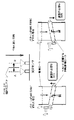
通常、回転駆動体のベルト表面への接離によってベルトが移動する距離は非常に微小で、回転駆動体の調整方向を判定することは難しいが、回転駆動体の接触時および離間時のベルト位置を検出することで、ベルトの調整方向の判定を容易化する。図6に示すように、ベルト上に取り付けられたマークか、またはトナーのパターンを光学センサで検出して、回転駆動体の移動方向を自動的に検出する。図6では、回転駆動部材が離間している時に描かれたパターンが、回転駆動部材の当接によってAまたはBの方向に移動したと仮定して調整が必要な方向を図示している(当然ながら回転駆動部材の当接によってパターンが移動しない場合、調整は不要である)。図6では一例として光学センサを2つ用いて、パターンからの反射強度が強くなった方向にベルトが移動したと判定する方法を示している。本装置により工程出荷時もしくはサービスマンがAかBかの情報に基づき回転駆動体の平行度の調整方向を決定すればよい。
【0029】
平行度調整の自動化を図り、上記のように検出されたベルト移動方向の情報に基づいて図5の偏心カム72をステッピングモータ等で回転させ、最適位置で停止させるようにする。ステッピングモータは電源がオンであればモータ回転軸の保持トルクを有するので、図5の調整レバー74をネジで固定する必要はなくなる。機械の立ち上げ時や、ジョブ間の画像調整中に同時に平行度調整を行うことにより常に画像ズレのない高画質を得ることができる。また、市場で部品を交換した場合に必要となる平行度の再調整にも容易に対応できる。これにより従来、工程やサービスマンの経験による特殊な技能に頼っていた調整が、容易に且つ短時間に行うことができるようになった。
【0030】
【発明の効果】
請求項1の画像形成装置によれば、回転駆動部材の回転軸と無端状ベルト部材を張架するローラとの平行度を調整可能としたので、回転駆動部材のベルトへの当接によって生じるベルト寄りの乱れを防止でき、ベルト寄りとベルト走行性を安定化できる。
【0031】
画像情報に応じたトナー像を担持する像担持体と、該像担持体に対向配置される中間転写体と、上記像担持体上のトナー像を中間転写体上に順次転写する一次転写手段と、中間転写体上に転写保持されたトナー像を記録媒体上に一括転写する二次転写手段と、二次転写後の中間転写体上の残留物を清掃するクリーニング手段とを備え、上記ベルト部材が中間転写体であれば、ベルト走行の安定化を図ることで微小な主走査画像ズレを防止できる。
【0032】
上記回転駆動部材のベルト部材への接触時の、離間時に対するベルト部材変位方向を検出可能な手段を有すれば、平行度調整方向の判定を試行錯誤的でなく容易化できる。そして検出されたベルト部材の変位方向情報に基づき、回転駆動部材の回転軸と無端状ベルト部材を張架するローラ部材との平行度を自動的に調整できれば、容易に且つ短時間に調整可能である。
【図面の簡単な説明】
【図1】本発明に係るタンデム型関節転写方式の画像形成装置の概略構成図である。
【図2】中間転写部の概略構成図である。
【図3】回転駆動部材と張架ローラが完全に平行でないためにベルト寄りが生じることを説明する図である。
【図4】回転駆動部材と張架ローラの平行度を保つために回転駆動体の回転軸を調整する様子を説明する図である。
【図5】2次転写ローラに平行度調整機構を適用した例を示す図である。
【図6】回転駆動体の接触時および離間時のベルト位置を検出する構成を説明する図である。
【符号の説明】
10 中間転写ベルト
71 2次店主アローラ
72 偏心カム
73 調整レバー支点
74 調整レバー
75 ローラ軸受[0001]
BACKGROUND OF THE INVENTION
The present invention relates to an image forming apparatus such as a copying machine, a printer, and a facsimile, and more particularly to an image forming apparatus provided with an intermediate transfer member.
[0002]
[Prior art]
As a conventional intermediate transfer type image forming apparatus, for example, from Patent Document 1, a photosensitive drum on which a toner image corresponding to an electrostatic latent image is formed and mounted, and a toner image on the photosensitive drum are transferred intermediately. An intermediate transfer belt, a primary transfer device for transferring the toner image on the photosensitive drum to the intermediate transfer belt, and a secondary transfer for secondary transfer of the toner images transferred on the intermediate transfer belt to a sheet at once. A configuration having a device is known.
[Patent Document 1]
Japanese Patent Laid-Open No. 5-323704
The intermediate transfer belt has a multilayer structure, and the base layer is made of, for example, a fluorine resin, PVD sheet, or polyimide resin that has little elongation, and the surface is covered with a smooth coat layer such as a fluorine resin. .
[0004]
In order to stably run the intermediate transfer belt, conventionally, a guide member attached to the end of the belt is brought into contact with the end on one side of the roller by a belt shifting force and rotated. In an apparatus in which no disturbance occurs in the belt, the belt can move stably in one direction due to the offset force. However, in a device in which a member that rotates at a constant speed, such as a cleaning brush or a transfer roller, contacts the belt from the outside, a phenomenon occurs in which the deviation of the belt is disturbed by the contact of the rotating member.
[0005]
When the belt misalignment is disturbed, the position of the image superimposed on the intermediate transfer belt is shifted, image misalignment occurs, and in a more severe case, the belt runs on the roller.
[0006]
In order to prevent the belt from being disturbed by the contact of the rotating member, it is important that the parallelism between the rotating shaft of the rotating member and the roller on which the belt is stretched is maintained with high accuracy. Has produced parallelism according to the accuracy of individual parts to prevent problems such as the belt running.
[0007]
[Problems to be solved by the invention]
However, due to the recent demand for higher image quality, the image resolution has increased, and it has become impossible to ignore the slight image misalignment caused by slight disturbance. In order to prevent a slight disturbance from occurring due to the contact of the rotating member, there is a limit in improving the component accuracy. In particular, the rotating member that comes into contact with the intermediate transfer unit from the outside is often a separate unit because of the structure of the machine or maintainability, and it is difficult to achieve parallelism without adjustment.
[0008]
Therefore, the present invention, for example, adjusts the parallelism of the rotation shaft of the rotation drive member that contacts the roller member around which the intermediate transfer belt is wound, so that the contact with the rotation drive member does not affect the belt side. It is an object of the present invention to obtain a good image with no image displacement.
[0009]
[Means for Solving the Problems]
According to the present invention, there is provided an image including an endless belt member stretched by at least two rollers, a driving unit that drives the belt member, and a rotational driving member that contacts and separates from the belt member. In the forming apparatus, the problem is solved by making it possible to adjust the parallelism between the rotation shaft of the rotation driving member and the roller that stretches the endless belt member.
[0010]
It is preferable to have means capable of detecting the direction of displacement of the belt member with respect to the time of separation when the rotational driving member contacts the belt member. It is more effective if the parallelism between the rotation shaft of the rotation driving member and the roller member that stretches the endless belt member can be automatically adjusted based on the detected displacement direction information of the belt member.
[0011]
DETAILED DESCRIPTION OF THE INVENTION
Hereinafter, the present invention will be described in detail based on illustrated examples.
FIG. 1 shows an example of the present invention, which is an electrophotographic apparatus of a tandem indirect transfer system. In the figure, reference numeral 100 is a copying apparatus main body, 200 is a paper feed table on which the copying apparatus is placed, 300 is a scanner mounted on the copying apparatus main body 100, and 400 is an automatic document feeder (ADF) mounted thereon.
[0012]
The copying machine main body 100 is provided with an endless belt-shaped intermediate transfer member 10 at the center. In the intermediate transfer body 10, the base layer is made of, for example, a fluororesin having a small elongation, or a rubber material having a large elongation is combined with a material that is difficult to stretch, such as canvas, and an elastic layer is provided thereon. The elastic layer is made of, for example, fluorine rubber or acrylonitrile-butadiene copolymer rubber. The surface of the elastic layer is covered with, for example, a coating layer having good smoothness by coating with a fluorine resin.
[0013]
In the illustrated example, the intermediate transfer member 10 is wound around three support rollers 14, 15, and 16 so as to be able to rotate and convey clockwise in the drawing. In this example, an intermediate transfer body cleaning device 17 for removing residual toner remaining on the intermediate transfer body 10 after image transfer is provided on the left side of the second support roller 15 among the three. Among the three rollers, four images of black, yellow, magenta, and cyan are formed on the intermediate transfer member 10 stretched between the first support roller 14 and the second support roller 15 along the conveyance direction. The tandem image forming apparatus 20 is configured by arranging the forming units 18 side by side. An exposure device 21 is further provided on the tandem image forming apparatus 20.
[0014]
On the other hand, a secondary transfer device 22 is provided on the side opposite to the tandem image forming apparatus 20 with the intermediate transfer body 10 interposed therebetween. In the illustrated example, the secondary transfer device 22 is arranged by passing a secondary transfer belt 24, which is an endless belt, between two rollers 23 and pressing it against the third support roller 16 via the intermediate transfer body 10. Then, the image on the intermediate transfer body 10 is transferred to a sheet. As this secondary transfer device, one using a secondary transfer roller is well known. The secondary transfer device 22 also has a sheet conveying function for conveying the image-transferred sheet to the fixing device 25. Of course, some secondary transfer devices 22 use transfer rollers (FIG. 2), and a non-contact charger may be arranged, but in those cases, it is difficult to provide this sheet conveying function together.
[0015]
A fixing device 25 for fixing the transferred image on the sheet is provided beside the secondary transfer device 22. The fixing device 25 is configured by pressing a pressure roller 27 against a fixing belt 26 that is an endless belt.
[0016]
In the illustrated example, under such a secondary transfer device 22 and a fixing device 25, a sheet reversing device 28 for reversing the sheet so as to record images on both sides of the sheet in parallel with the tandem image forming device 20 described above. It also has.
[0017]
A case of making a copy using this color electrophotographic apparatus will be described. First, a document is set on the document table 30 of the automatic document feeder 400. Alternatively, the automatic document feeder 400 is opened, a document is set on the contact glass 32 of the scanner 300, and the automatic document feeder 400 is closed and pressed by it. When a start switch (not shown) is pressed, when a document is set on the automatic document feeder 400, the document is transported and moved onto the contact glass 32, and then the document is set on the other contact glass 32. Immediately drives the scanner 300 and travels through the first traveling body 33 and the second traveling body 34. Then, the first traveling body 33 emits light from the light source and further reflects the reflected light from the document surface toward the second traveling body 34, and is reflected by the mirror of the second traveling body 34 and passes through the imaging lens 35. The document is placed in the reading sensor 36 and the original content is read.
[0018]
On the other hand, when the start switch is pressed, one of the support rollers 14, 15 and 16 is rotationally driven by a drive motor (not shown), the other two support rollers are driven to rotate, and the intermediate transfer member 10 is rotated and conveyed. become. At the same time, the individual image forming means 18 rotates the photoconductor 40 to form black, yellow, magenta, and cyan monochrome images on each photoconductor 40. Then, along with the conveyance of the intermediate transfer member 10, these single color images are sequentially transferred to form a composite color image on the intermediate transfer member 10.
[0019]
Also, by pressing the start switch, one of the paper feed rollers 42 of the paper feed table 200 is selectively rotated, and the sheet is fed out from one of the paper feed cassettes 44 provided in the paper bank 43 in multiple stages. The sheets are separated one by one and are put into a paper feed path 46, transported by a transport roller 47, guided to a paper feed path 48 in the copying machine main body 100, and abutted against a registration roller 49 and stopped. Alternatively, the sheet feed roller 50 is rotated to feed out the sheets on the manual feed tray 51, separated one by one by the separation roller 52, put into the manual feed path 53, and abutted against the registration roller 49 and stopped.
[0020]
Then, the registration roller 49 is rotated in synchronization with the composite color image on the intermediate transfer member 10, the sheet is fed between the intermediate transfer member 10 and the secondary transfer device 22, and transferred by the secondary transfer device 22. A color image is recorded on the sheet. The image-transferred sheet is conveyed by the secondary transfer device 22 and sent to the fixing device 25. The fixing device 25 applies heat and pressure to fix the transferred image, and then the switching roller 55 is used to switch the discharge roller. The paper is discharged at 56 and stacked on the paper discharge tray 57. Alternatively, it is switched by the switching claw 55 and put into the sheet reversing device 28, where it is reversed and guided again to the transfer position, and an image is recorded also on the back surface, and then discharged onto the discharge tray 57 by the discharge roller 56. On the other hand, the intermediate transfer body 10 after image transfer is prepared by the intermediate transfer body cleaning device 17 to remove residual toner remaining on the intermediate transfer body 10 after the image transfer, and to be used again for image formation by the tandem image forming apparatus 20. .
[0021]
Here, the registration roller 49 is generally used while being grounded, but it is also possible to apply a bias for removing paper dust from the sheet. For example, a bias is applied using a conductive rubber roller. When a conductive NBR rubber having a diameter of φ18 and a surface of 1 mm in thickness is used, the electric resistance is about 10E9 Ωcm in terms of volume resistance of the rubber material, and a voltage of about −800 V is applied to the toner transfer side (front side) as the applied voltage. Applied, a voltage of about +200 V is applied to the back side of the paper. Generally, in the intermediate transfer system, it is difficult for paper dust to move to the photoconductor, so that it is not necessary to consider paper dust transfer and may be grounded. Further, a DC bias is applied as the applied voltage, but this may be an AC voltage having a DC offset component in order to more uniformly charge the sheet.
[0022]
Thus, the paper surface after passing through the registration roller 49 to which a bias is applied is slightly charged on the negative side. Therefore, in the transfer from the intermediate transfer body 10 to the sheet, there are cases where the transfer conditions are changed and the transfer conditions are changed as compared with the case where no voltage is applied to the registration roller 49.
[0023]
The configuration of the present invention will be described in detail below. In an apparatus capable of adjusting the parallelism between a rotation shaft of a rotary drive member that contacts and separates from an endless belt member and a roller member that stretches the endless belt member, a belt member used in an image forming apparatus ( Intermediate transfer belts, paper transfer belts, transport belts, etc.) are considered to be effective in preventing the belt from running on rollers and improving belt running stability, but do not cause image misalignment especially on the intermediate transfer belt. Therefore, there is a possibility that high accuracy that is higher than the accuracy (parallelism) obtained only by managing the accuracy of each component configured may be required. Therefore, in the following, an example in which the present invention is used for an intermediate transfer belt will be described. I will explain.
[0024]
FIG. 2 is a schematic configuration diagram of the intermediate transfer unit. The intermediate transfer belt 10 is in contact with a brush roller 70 for applying a lubricant and a secondary transfer roller 71 for paper transfer disposed in the cleaning device 17. Each member has a drive separately from the intermediate transfer belt 10, and actively rotates at a constant speed when contacting the intermediate transfer belt. These rotating members may have a structure that is separated from the intermediate transfer belt from the viewpoint of cleaning performance and long life, and when applying lubricant to the belt (brush roller 70) or when transferring to paper (two) Only the next transfer roller 71) is brought into contact with the intermediate transfer belt 10 from the outside.
[0025]
On the other hand, in order to make the intermediate transfer belt 10 run stably, a system is widely used in which a detent guide attached to the intermediate transfer belt is abutted against one end of the roller (closed to one side). The moving direction of the belt is determined by the moving force of the driving roller for driving the belt. However, when the brush roller 70 and the transfer roller 71 abut from the outside of the belt, it is shown in FIG. 3 that the roller supporting the intermediate transfer belt 10 and the rotation axis of the brush roller 70 and the transfer roller 71 are not completely parallel. As described above, the force received by the belt from the rotating member is decomposed, and a part of the force acts in the direction of the belt. If such a force is applied, the intermediate transfer belt is displaced, causing the intermediate transfer belt to meander, and in the worst case, it may cause the belt to run on the roller. Conventionally, the degree of parallelism between the rotating shaft of the rotating member and the roller on which the belt is stretched is maintained with high accuracy by the accuracy of the individual components configured so that the deviation of the belt is not disturbed by the contact of the rotating member. The problem of getting on has been prevented. However, even if the accuracy of individual parts is managed, there is a limit to the degree of parallelism that can be obtained, so that a minute disturbance occurs in the intermediate transfer belt due to the contact of the rotating member. Normally, the amount of misalignment in the main scanning direction of the intermediate transfer belt due to the contact of the rotation drive member is about 40 μm at the maximum, so this misalignment has not been a problem in the past. In the demand for higher image quality and higher resolution such as smaller diameters, it is no longer negligible. This is because the slight meandering of the belt may cause a minute main scanning image shift and may become manifest as color variation within a page or between pages.
[0026]
Therefore, as shown in FIG. 4, a rotating member (a brush roller or a driven roller) that contacts and separates a roller (a driving roller or a driven roller) that stretches the intermediate transfer belt 10 by adjusting a rotation shaft of a rotating member that contacts the intermediate transfer belt 10. By making the parallelism with the transfer roller as close as possible to 0, the component force that the belt receives in the shifting direction when the rotating member comes into contact is 0, and the belt is not shifted. When adjusting the parallelism of the rotary drive body that contacts and separates from the intermediate transfer belt 10, the meshing of the gear and the like necessary for power transmission of the rotary drive body changes, and there is a concern about contact of the gears. Is drawn exaggerating the deviation in parallelism between the intermediate transfer belt stretching roller and the rotation drive roller, and the amount that normally needs to be adjusted is considered to be about 0.5 mm in width (parallelism 0.5 or more). The degree of parallelism can be achieved by individual component accuracy control). If the side opposite to the drive input of the rotary drive body is moved by 0.5 mm, and if the drive rotary body length (belt width) is about 350 mm, the drive side movement is about 0.02 mm. There is no problem with the meshing. Considering the use conditions of gears currently used in actual machines, it is considered that a shift of about 0.1 M (M is a gear module) has no practical problem with gear meshing.
[0027]
FIG. 5 is an example in which parallelism adjustment is applied to the secondary transfer roller 71, and an outline of the adjustment mechanism will be described. In FIG. 5, the secondary transfer roller 71 is illustrated in contact with the intermediate transfer belt 10, but the secondary transfer roller 71 has a structure that contacts and separates the belt with respect to the illustrated fulcrum. . An adjustment mechanism is attached only to the front side of the secondary transfer roller 71 where there is no drive input gear. By rotating the eccentric cam 72, the adjustment lever 74 swings around the adjustment lever fulcrum 73. Thus, the front bearing of the secondary transfer roller 71 attached to the adjustment lever 74 is configured to swing. The width for adjusting the secondary transfer roller 71 is about 0.5 mm at the maximum, and it is more accurate to make the distance from the adjustment lever fulcrum 73 to the eccentric cam 72 larger than the distance from the adjustment lever fulcrum 73 to the secondary transfer bearing 75. Adjustment is possible. After the adjustment, it is necessary to fix the adjustment lever 74 with a screw or the like so that the position of the secondary transfer bearing does not change with time.
[0028]
Normally, the distance that the belt moves due to the contact and separation of the rotational drive body from the belt surface is very small and it is difficult to determine the adjustment direction of the rotational drive body, but the belt position when the rotational drive body is in contact with and separated from the belt surface This facilitates determination of the belt adjustment direction. As shown in FIG. 6, the mark attached to the belt or the toner pattern is detected by an optical sensor, and the moving direction of the rotary drive is automatically detected. FIG. 6 illustrates a direction that needs to be adjusted on the assumption that the pattern drawn when the rotary drive members are separated from each other is moved in the direction A or B by the contact of the rotary drive members. However, if the pattern does not move due to the contact of the rotary drive member, no adjustment is required). FIG. 6 shows a method of using two optical sensors as an example and determining that the belt has moved in the direction in which the reflection intensity from the pattern has increased. The adjustment direction of the parallelism of the rotary drive body may be determined by this apparatus based on the information of whether the process is shipped or the service person is A or B.
[0029]
The parallelism adjustment is automated, and the eccentric cam 72 of FIG. 5 is rotated by a stepping motor or the like based on the information on the belt moving direction detected as described above, and stopped at the optimum position. Since the stepping motor has the holding torque of the motor rotating shaft when the power is on, it is not necessary to fix the adjusting lever 74 of FIG. 5 with a screw. By adjusting the parallelism at the same time when the machine is started up or during image adjustment between jobs, it is possible to always obtain high image quality without image displacement. Moreover, it is possible to easily cope with readjustment of parallelism required when parts are replaced in the market. As a result, adjustments that have conventionally relied on special skills based on the experience of the processes and service personnel can now be performed easily and in a short time.
[0030]
【The invention's effect】
According to the image forming apparatus of the first aspect, since the parallelism between the rotation shaft of the rotation driving member and the roller that stretches the endless belt member can be adjusted, the belt generated by the contact of the rotation driving member with the belt. It is possible to prevent misalignment of the shift and stabilize the belt shift and belt running performance.
[0031]
An image carrier that carries a toner image according to image information; an intermediate transfer member that is disposed opposite the image carrier; and a primary transfer unit that sequentially transfers the toner image on the image carrier onto the intermediate transfer member; The belt member comprising: a secondary transfer unit that collectively transfers a toner image transferred and held on the intermediate transfer member onto a recording medium; and a cleaning unit that cleans residues on the intermediate transfer member after the secondary transfer. If the intermediate transfer member is used, it is possible to prevent a minute main scanning image deviation by stabilizing the belt running.
[0032]
If there is a means capable of detecting the direction of displacement of the belt member relative to the separation when the rotational drive member is in contact with the belt member, the determination of the parallelism adjustment direction can be facilitated without trial and error. If the parallelism between the rotation shaft of the rotation driving member and the roller member that stretches the endless belt member can be automatically adjusted based on the detected displacement direction information of the belt member, it can be adjusted easily and in a short time. is there.
[Brief description of the drawings]
FIG. 1 is a schematic configuration diagram of a tandem joint transfer type image forming apparatus according to the present invention.
FIG. 2 is a schematic configuration diagram of an intermediate transfer unit.
FIG. 3 is a diagram for explaining that a belt shift occurs because a rotation drive member and a tension roller are not completely parallel.
FIG. 4 is a diagram for explaining a state in which the rotation shaft of the rotary drive body is adjusted in order to maintain the parallelism of the rotary drive member and the stretching roller.
FIG. 5 is a diagram illustrating an example in which a parallelism adjusting mechanism is applied to a secondary transfer roller.
FIG. 6 is a diagram illustrating a configuration for detecting a belt position at the time of contact and separation of a rotary drive body.
[Explanation of symbols]
10 Intermediate transfer belt 71 Secondary store owner Aroller 72 Eccentric cam 73 Adjustment lever fulcrum 74 Adjustment lever 75 Roller bearing