JP2005017103A - Device for measuring center position shift, for constructed conduit - Google Patents
Device for measuring center position shift, for constructed conduit Download PDFInfo
- Publication number
- JP2005017103A JP2005017103A JP2003182040A JP2003182040A JP2005017103A JP 2005017103 A JP2005017103 A JP 2005017103A JP 2003182040 A JP2003182040 A JP 2003182040A JP 2003182040 A JP2003182040 A JP 2003182040A JP 2005017103 A JP2005017103 A JP 2005017103A
- Authority
- JP
- Japan
- Prior art keywords
- conduit
- center position
- laid
- measuring device
- laying
- Prior art date
- Legal status (The legal status is an assumption and is not a legal conclusion. Google has not performed a legal analysis and makes no representation as to the accuracy of the status listed.)
- Pending
Links
Images


Landscapes
- Length Measuring Devices By Optical Means (AREA)
Abstract
Description
【0001】
【発明の属する技術分野】
本発明は、敷設導管中心位置ずれ測定装置、特に横穴に敷設された導管の中心位置が、予定軸線に対しその敷設距離位置に応じてどの程度ずれているのかを簡易に測定できるようにした敷設導管中心位置ずれ測定装置に関するものである。
【0002】
【従来の技術】
例えば、下水管の埋設に当たっては、敷設される導管の中心が上下方向にずれていると水が溜まってしまうので、敷設される導管の中心位置、すなわち中心軸の一致が要求される。しかしながら穴の掘削においては、地盤の影響を受け、穴が必ずしも一直線に掘削されるとは限らず、部分的にその中心位置がずれた状態で掘削されることもある。
【0003】
このように穴が部分的にその中心位置がずれた状態で掘削されたときにも、どの位置でどれほどその中心位置が予定軸線からずれているかが予め分かれば、導管を敷設する際、その位置の中心位置のずれを考慮に入れて敷設或いは敷設された導管の修正作業を行うことにより、水が溜まってしまうことのない導管の敷設をすることができる。
【0004】
このように敷設された導管の中心の予定軸線からのずれを測定する従来の測定装置として、レーザ装置等を用いて測定する方法が採られていた。
【0005】
【発明が解決しようとする課題】
しかしながら、従来のようにレーザ装置等は精確に測定することはできるが、装置自体が高価すぎる欠点があった。
【0006】
本発明は、上記の欠点を解決することを目的としており、グラスファイバの先端を所定間隔で、例えば十字形に点灯させた状態で、筒体を導管の内壁面に沿って移動させると共に、管端に設けられた測器でその予定軸線上にあるべきグラスファイバの先端の十字形の点灯位置を求め、敷設導管の管端からの距離位置のその中心のずれを簡易でしかも安価に得られるようにした敷設導管中心位置ずれ測定装置を提供することを目的としている。
【0007】
【課題を解決するための手段】
上記の目的を解決するため、本発明の敷設導管中心位置ずれ測定装置は横穴に敷設された導管の管端に測器を設置し、予定軸線に対する敷設された導管のその中心位置のずれを測定する敷設導管中心位置ずれ測定装置において、敷設された導管内に挿入され移動する筒体と、敷設された導管内径の1/2から筒体外径の1/2を引いた長さを有し、筒体の中心からその径方向放射状に、筒体の外径表面に設けられた複数の脚部と、予め定められた間隔で筒体の径方向放射状に少なくとも4方向に配列され点灯される筒体に設けられた点灯表示手段とを備え、敷設された導管の予定軸線に対するその中心位置のずれが測定されるようにしたことを特徴としている。
【0008】
そして上記脚部は、先端部にエッジ部又はローラを備え、当該エッジ部又はローラで敷設された導管の内径壁面を移動するように構成されている。
【0009】
また上記筒体は、敷設された導管の内径壁面を上記脚部が密着移動するためのスプリングを有する密着用脚部を備え、脚部が敷設された導管の内径壁面の追従密着性を確保するように構成されていてもよい。
【0010】
更に上記筒体は、脚部を自在に交換できる係合手段や長さを自在に可変できる可変手段を備え、脚部の交換や脚部の長さの調整により種々の導管の内径に適応されるようになっている。
【0011】
上記点灯表示手段は、グラスファイバや発光ダイオードが用いられる。
【0012】
移動する筒体は敷設された導管と中心が同一であるので、敷設された導管の予定軸線と筒体に設けられた点灯表示手段の点灯表示とから、敷設された導管の任意位置でのその中心位置のずれが求められる。
【0013】
そして筒体の移動性を良くするため、その外径表面にエッジ部又はローラを有する脚部を設けても、敷設された導管と筒体との同心性は保持され、また長さを異にする脚部の交換或いは脚部の長さの可変によっても、径を異にする敷設導管に対して、任意位置でのその中心位置のずれを求めることができる。
【0014】
【発明の実施の形態】
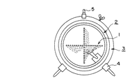
図1は本発明に係る敷設導管中心位置ずれ測定装置の一実施例正面図、図2は図1の右側面図を示している。
【0015】
図1,図2において、敷設導管中心位置ずれ測定装置は、前面に十字形状の点灯表示手段1を有する円筒部2、円筒を形成すると共に円筒部2を収納する円筒状枠体3及び円筒状枠体3に取り付けられた2つの脚部4を備えている。5は持ち運び用の把手を表している。この把手5は測定のとき外される。
【0016】
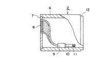
円筒部2は、図3の円筒部の一実施例正面図、図4のその右側面図に示されている様、円筒6の一端にアクリル板等の透明な合成樹脂製円板7が固着されており、円筒6の他端は開口されている。合成樹脂製円板7には、円筒6の中心から放射状に4本、すなわち十字形状に小穴が穿たれ、その中心部を原点にグラスファイバ8の先端が縦方向及び横方向に各々、奇数個一直線状に予め定められた間隔で十字形状に配置固定されている。グラスファイバ8の他端は円筒6の内部の適当な位置に固定された光導入部9に収束され、当該光導入部9に装着された光源10から発する光がグラスファイバ8に導入されるようになっている。
【0017】
光源10は、例えば簡易な懐中電灯などが用いられ、円筒6の開口端側からそのスイッチ部11を回転させるなどでスイッチオンにすることにより、一定間隔で並べられた十字形状の光を合成樹脂製円板7に点灯させることができる。
【0018】
なお、円筒6の開口端側には位置決め用の段差12が設けられている。そして図中のグラスファイバ8の点線はその存在及び接続を模式的に示したもので、図の複雑性を回避するための方便で描かれている。
【0019】
図5は円筒状枠体の一実施例正面図、図6は図5の右側面図を示している。
【0020】
図5,図6において、円筒状枠体3は、環状の前枠13、有底円形状の後枠14及び3個の横フレーム15で構成され、これらはねじ止めにより組み立てられている。すなわち前枠13と後枠14との間に、図6に示されている如く、その頂点に配置された1個の横フレーム15、そして当該頂点に配置された横フレーム15と残りの2個の横フレーム15とで二等辺三角形を構成する形状にして円筒状枠体3が組み立てられている。
【0021】
有底円形状の後枠14の底部には、図4で説明の円筒6に設けられた位置決め用段差12を用いて当該円筒6が嵌め込まれるための窪みが形成されており、合成樹脂製円板7側の面が図6に向かって左側となるように円筒状枠体3に図3、図4図示の円筒部2が嵌め込まれ収納されたとき、当該円筒部2を固定するための蝶ねじ16が、環状の前枠13に設けられている。
【0022】
円筒状枠体3の外径表面には、更に上記二等辺三角形を構成する2個の横フレーム15の位置に、前側に2個、後側に2個の脚部4が、円筒状枠体3の中心から径方向に向かってそれぞれ取り付けられている。当該脚部4は、その先端部にアイススケ−ト靴にもちいられているのと同様のエッジ部17を備えると共に、敷設された導管内径の1/2から円筒状枠体3の外径の1/2を引いた長さを有する。すなわち円筒状枠体3のその中心から脚部4の先端までは、敷設された導管内径の1/2の長さとされる。なお、図1で説明した把手5は頂点に配置された横フレーム15に取り付けられ、運搬に供されている。
【0023】
この様に構成された本発明に係る敷設導管中心位置ずれ測定装置による敷設された導管の予定軸線からの中心のずれの測定の仕方を次の誇張図を用いて説明する。
【0024】
図7は横穴に敷設された導管の予定軸線からの中心位置ずれを測定する一実施例誇張説明図を示している。
【0025】
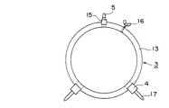
図7においては、水が途中に溜まらないように下向きにわずかに傾斜を持って掘られた横穴に、複数の導管が接続されて敷設されたその一部分の状態を示している。十字線付の望遠鏡18が設置された導管口から、スイッチ部11のオンによりグラスファイバ8の先端が点灯された合成樹脂製円板7を手前側、すなわち十字線付の望遠鏡18側に、図1に示された本発明に係る敷設導管中心位置ずれ測定装置をその脚部4を下側にして導管内に挿入し、例えば敷設された導管の反対側から牽引することにより、敷設された導管内を脚部4のエッジ部17で案内され、図7の左側から右方向に円筒状枠体3を移動させることができる。
【0026】
円筒状枠体3に設けられた脚部4のそれぞれは、当該円筒状枠体3の中心、すなわち円筒部2の中心から脚部4のエッジ部17の先端までの距離が敷設されている導管の内径の1/2であるので、円筒部2の中心は常に敷設されている導管の中心と一致して移動する。この円筒部2の中心は合成樹脂製円板7に配列された十字形状グラスファイバ8の縦横方向の原点のグラスファイバ8に一致している。
【0027】
導管口に設置された十字線付の望遠鏡18の軸L0 を当該導管口の中心に合わせた後、観測者がこの十字線付の望遠鏡18の軸L0 と敷設された導管口から距離Xにある円筒部2の前面に設けられた合成樹脂製円板7の十字形状グラスファイバ8の原点位置の点灯との一致を観測すれば、導管が予定軸線に敷設されていることを示している。しかしながら、図7図示の如く、十字線付の望遠鏡18の軸L0 と十字形状グラスファイバ8の原点とのずれYが観測されたときには、そのずれたグラスファイバ8の点灯位置を読み取ることにより、管端、すなわち導管口からの距離Xにおける中心位置ずれYを求めることができる。つまり導管口からの任意距離Xにおける敷設導管の予定軸線からの中心位置ずれを所望の間隔毎に、また連続的に測定することができる。
【0028】
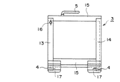
図8は本発明に係る敷設導管中心位置ずれ測定装置の他の実施例正面図、図9は図8の右側面図を示している。
【0029】
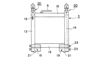
図8,図9において、図1,図2と同じものは同じ符号が付されている。同じ符号が付されているものは、構造、作用が同じであるのでその説明は省略する。図8,図9が図1,図2と異なるところは、脚部19の構造と円筒状枠体3の前後にそれぞれ密着用脚部20が新たに設けられている点である。
【0030】
脚部19はその先端に回転自在のローラ21を備えると共に、スライドロッド22とロックねじ23とを備えている。先端に当該ローラ21を備えた脚部19は、敷設された導管内径の1/2から円筒状枠体3の外径の1/2を引いた長さを有する。すなわち円筒状枠体3の中心から脚部4の先端までは、敷設された導管内径の1/2の長さとされる。脚部19はその先端に回転自在のローラ21を備えているので、円筒状枠体3は敷設された導管内の移動が容易となる。
【0031】
そして2つのロックねじ23または1つのロックねじ23を用いてスライドロッド22を伸縮してロックすることにより、或いは更に長い別のスライドロッド22と交換することにより、円筒状枠体3の中心から脚部4の先端までの距離を自在に伸縮することができ、径を異にする種々の敷設導管に対応することができるようになっている。
【0032】
円筒状枠体3に取り付けられた2つの脚部19とで二等辺三角形をなすその頂点位置に設けられた密着用脚部20は、スプリング24、移動部材25、固定部材26などを備えている。
【0033】
図10に示されている如く、固定部材26は、内部にスプリング24と移動部材25とを収納する穴28が形成されており、そして当該固定部材26は円筒状枠体3の前枠13にねじ27で固着されている。移動部材25は、その先端部が導管の内壁面を押圧すると共に摺動し易い丸みをおびた断面が卵型に形成されると共に、内部にはスプリング24を収納する穴29が設けられ、上記固定部材26の穴28内を自在に摺動する構造を備えている。30は移動部材25に固着された抜け防止用のスライド部材であり、固定部材26に固着されたガイド部材31によって摺動自在に移動できるようになっている。
【0034】
この様な脚部19と密着用脚部20とを備えた円筒状枠体3が、その密着用脚部20を圧縮して敷設された導管内に挿入されると、密着用脚部20内に装着されているスプリング24の弾性力により、当該密着用脚部20の卵型に形成された先端部が導管の内壁面を押圧し、円筒状枠体3に取り付けられた2つの脚部19が、導管の内壁面とより一層密着した状態となる。従って、円筒状枠体3と敷設導管との中心位置の一致が確保され、敷設導管の予定軸線からのずれの観測の精度を向上させることができる。
【0035】
図10に示された密着用脚部20を図1に示された敷設導管中心位置ずれ測定装置に設置してもよいことは言うまでもない。
【0036】
以上の説明では、円筒状枠体3の内部に円筒部2を設け、当該円筒部2の前面に十字形状グラスファイバ8の先端を設けた合成樹脂製円板7を取り付ける構造としているが、十字形状グラスファイバ8の先端を設けた合成樹脂製円板7を円筒状枠体3の前面に直接取り付ける構造とすることもできる。またグラスファイバ8の先端を点灯させるようにしているが、グラスファイバ8に換え、発光ダイオードを用い、各発光ダイオードを点灯させるようになっていてもよい。そしてグラスファイバ8は、円筒部2の中心から径方向放射状に4本の十字形状で説明したが、これを等角度で6本、8本に増やせば、ずれの方向もより正確に測定することができるようになる。
【0037】
【発明の効果】
以上説明した如く、本発明によれば、簡易なグラスファイバと懐中電灯とを用いて簡易に測定ができ、円筒状枠体を敷設された導管内径壁面に沿って追従した形態で移動させることができ、敷設された導管の予定軸線に対するずれ位置をより正確に測定することができる。
【0038】
また脚部を交換することにより、或いは脚部の長さが自由に伸縮することができるので、種々の導管に対して対処できる利点を有する。
【図面の簡単な説明】
【図1】本発明に係る敷設導管中心位置ずれ測定装置の一実施例正面図である。
【図2】図1の右側面図である。
【図3】円筒部の一実施例正面図である。
【図4】図3の右側面図である。
【図5】円筒状枠体の一実施例正面図である。
【図6】図5の右側面図である。
【図7】横穴に敷設された導管の予定軸線からの中心位置ずれを測定する一実施例誇張説明図である。
【図8】本発明に係る敷設導管中心位置ずれ測定装置の他の実施例正面図である。
【図9】図8の右側面図である。
【図10】密着用脚部の一実施例拡大断面図である。
【符号の説明】
1 点灯表示手段
2 円筒部
3 円筒状枠体
4 脚部
6 円筒
7 合成樹脂製円板
8 グラスファイバ
10 光源
13 前枠
14 後枠
15 横フレーム
17 エッジ部
19 脚部
20 密着用脚部
21 ローラ[0001]
BACKGROUND OF THE INVENTION
The present invention is a laying conduit center position measuring apparatus, and more particularly, a laying that can easily measure how much the center position of a conduit laid in a horizontal hole is shifted from a planned axis according to the laying distance position. The present invention relates to a conduit center misalignment measuring apparatus.
[0002]
[Prior art]
For example, when embedding a sewer pipe, water accumulates if the center of the pipe to be laid is shifted in the vertical direction, so that the center position of the pipe to be laid, that is, the center axis must be matched. However, in the excavation of a hole, due to the influence of the ground, the hole is not necessarily excavated in a straight line, and may be excavated with the center position partially shifted.
[0003]
Even when a hole is excavated with its center position partially shifted in this way, if it is known in advance at what position and how much its center position deviates from the planned axis line, when laying a conduit, that position By taking into account the shift of the center position of the pipe, or by performing a correction operation of the pipe that has been laid or laid, it is possible to lay the pipe without causing water to accumulate.
[0004]
As a conventional measuring device for measuring the deviation of the center of the conduit laid in this way from the planned axis, a method of measuring using a laser device or the like has been adopted.
[0005]
[Problems to be solved by the invention]
However, the conventional laser apparatus can accurately measure, but the apparatus itself has a drawback of being too expensive.
[0006]
An object of the present invention is to solve the above-mentioned drawbacks, and while moving the cylindrical body along the inner wall surface of the conduit with the tip of the glass fiber lit at a predetermined interval, for example, in a cross shape, The cross-shaped lighting position of the tip of the glass fiber that should be on the planned axis line is obtained with a measuring instrument provided at the end, and the deviation of the center of the distance position from the pipe end of the laid conduit can be obtained easily and inexpensively. An object of the present invention is to provide an apparatus for measuring the displacement of the center position of a laid conduit.
[0007]
[Means for Solving the Problems]
In order to solve the above-mentioned object, the installed pipe center position deviation measuring device of the present invention installs a measuring instrument at the pipe end of the pipe installed in the horizontal hole, and measures the deviation of the center position of the installed pipe with respect to the planned axis. In the laying conduit center position deviation measuring apparatus, a cylinder that is inserted and moved in the laid conduit, and a length obtained by subtracting ½ of the cylinder outer diameter from ½ of the laid conduit inner diameter, A plurality of legs provided on the outer diameter surface of the cylinder, radially from the center of the cylinder, and cylinders that are arranged and lit in at least four directions radially in the radial direction of the cylinder at predetermined intervals And a lighting display means provided on the body, wherein a deviation of the center position of the laid conduit with respect to a predetermined axis is measured.
[0008]
And the said leg part is equipped with the edge part or roller at the front-end | tip part, and is comprised so that the inner diameter wall surface of the conduit | pipe laid by the said edge part or roller may be moved.
[0009]
Further, the cylindrical body includes a contact leg portion having a spring for allowing the leg portion to move in close contact with an inner wall surface of the laid conduit, and ensures follow-up adhesion of the inner wall surface of the conduit on which the leg portion is laid. It may be configured as follows.
[0010]
Further, the cylindrical body is provided with engaging means for freely changing the leg portion and variable means for freely changing the length, and is adapted to the inner diameters of various conduits by changing the leg portion or adjusting the length of the leg portion. It has become so.
[0011]
As the lighting display means, a glass fiber or a light emitting diode is used.
[0012]
Since the moving cylinder has the same center as that of the laid pipe, from the planned axis of the laid pipe and the lighting display of the lighting display means provided on the cylinder, the pipe at the arbitrary position of the laid pipe is displayed. Deviation of the center position is required.
[0013]
And in order to improve the mobility of the cylindrical body, even if a leg portion having an edge portion or a roller is provided on the outer diameter surface, the concentricity between the laid conduit and the cylindrical body is maintained, and the length is different. The displacement of the center position at an arbitrary position can be obtained for the laying conduits having different diameters also by exchanging the legs or changing the length of the legs.
[0014]
DETAILED DESCRIPTION OF THE INVENTION
FIG. 1 is a front view of an embodiment of a laying conduit center position deviation measuring apparatus according to the present invention, and FIG. 2 is a right side view of FIG.
[0015]
1 and 2, a laying conduit center position deviation measuring device includes a
[0016]
As shown in the front view of one embodiment of the cylindrical portion in FIG. 3 and the right side view in FIG. 4, the
[0017]
As the
[0018]
A
[0019]
FIG. 5 is a front view of an embodiment of a cylindrical frame, and FIG. 6 is a right side view of FIG.
[0020]
5 and 6, the
[0021]
The bottom of the bottomed circular
[0022]
On the outer diameter surface of the
[0023]
A method of measuring the deviation of the center of the laid conduit from the planned axis by the laid conduit center displacement measuring apparatus according to the present invention constructed as described above will be described with reference to the following exaggerated view.
[0024]
FIG. 7 shows an exaggerated explanatory view of an embodiment for measuring a center position deviation from a predetermined axis of a conduit laid in a horizontal hole.
[0025]
FIG. 7 shows a partial state in which a plurality of conduits are connected to a horizontal hole dug with a slight inclination downward so that water does not collect in the middle. From the conduit port where the
[0026]
Each of the
[0027]
After aligning the axis L 0 of the
[0028]
FIG. 8 is a front view of another embodiment of the laying conduit center displacement measuring apparatus according to the present invention, and FIG. 9 is a right side view of FIG.
[0029]
8 and 9, the same components as those in FIGS. 1 and 2 are denoted by the same reference numerals. Components having the same reference numerals have the same structure and operation, and therefore the description thereof is omitted. 8 and 9 are different from FIGS. 1 and 2 in that the structure of the
[0030]
The
[0031]
The
[0032]
The
[0033]
As shown in FIG. 10, the fixing
[0034]
When the
[0035]
Needless to say, the
[0036]
In the above description, the
[0037]
【The invention's effect】
As described above, according to the present invention, measurement can be easily performed using a simple glass fiber and a flashlight, and the cylindrical frame body can be moved in a form following the inner wall surface of the conduit. The displacement position of the installed conduit with respect to the predetermined axis can be measured more accurately.
[0038]
Further, since the leg portion can be exchanged or the length of the leg portion can be freely expanded and contracted, there is an advantage that it is possible to cope with various conduits.
[Brief description of the drawings]
FIG. 1 is a front view of an embodiment of a laying conduit center misalignment measuring apparatus according to the present invention.
FIG. 2 is a right side view of FIG.
FIG. 3 is a front view of an embodiment of a cylindrical portion.
4 is a right side view of FIG. 3. FIG.
FIG. 5 is a front view of an embodiment of a cylindrical frame.
6 is a right side view of FIG. 5. FIG.
FIG. 7 is an exaggerated explanatory view of an embodiment for measuring a center position deviation from a predetermined axis of a conduit laid in a horizontal hole.
FIG. 8 is a front view of another embodiment of the laying conduit center position deviation measuring device according to the present invention.
FIG. 9 is a right side view of FIG.
FIG. 10 is an enlarged cross-sectional view of an embodiment of a contact leg portion.
[Explanation of symbols]
DESCRIPTION OF SYMBOLS 1 Illumination display means 2
Claims (8)
敷設された導管内に挿入され移動する筒体と、
敷設された導管内径の1/2から筒体外径の1/2を引いた長さを有し、筒体の中心からその径方向放射状に、筒体の外径表面に設けられた複数の脚部と、
予め定められた間隔で筒体の径方向放射状に少なくとも4方向に配列され点灯される筒体に設けられた点灯表示手段と
を備え、敷設された導管の予定軸線に対するその中心位置のずれが測定されるようにしたことを特徴とする敷設導管中心位置ずれ測定装置。In the installed conduit center position deviation measuring device that installs a measuring instrument at the tube end of the conduit laid in the horizontal hole and measures the deviation of the center position of the laid conduit with respect to the planned axis line,
A cylinder that is inserted into a laid conduit and moves;
A plurality of legs having a length obtained by subtracting ½ of the outer diameter of the cylinder from ½ of the inner diameter of the laid conduit and radially provided from the center of the cylinder in the radial direction thereof And
Lighting indicator means provided on a cylinder which is arranged and lit in at least four directions radially in the radial direction of the cylinder at predetermined intervals, and the deviation of the center position of the laid conduit with respect to the planned axis is measured A laying conduit center position deviation measuring device characterized by being made.
Priority Applications (1)
| Application Number | Priority Date | Filing Date | Title |
|---|---|---|---|
| JP2003182040A JP2005017103A (en) | 2003-06-26 | 2003-06-26 | Device for measuring center position shift, for constructed conduit |
Applications Claiming Priority (1)
| Application Number | Priority Date | Filing Date | Title |
|---|---|---|---|
| JP2003182040A JP2005017103A (en) | 2003-06-26 | 2003-06-26 | Device for measuring center position shift, for constructed conduit |
Publications (1)
| Publication Number | Publication Date |
|---|---|
| JP2005017103A true JP2005017103A (en) | 2005-01-20 |
Family
ID=34182530
Family Applications (1)
| Application Number | Title | Priority Date | Filing Date |
|---|---|---|---|
| JP2003182040A Pending JP2005017103A (en) | 2003-06-26 | 2003-06-26 | Device for measuring center position shift, for constructed conduit |
Country Status (1)
| Country | Link |
|---|---|
| JP (1) | JP2005017103A (en) |
Cited By (2)
| Publication number | Priority date | Publication date | Assignee | Title |
|---|---|---|---|---|
| CN112067299A (en) * | 2020-09-11 | 2020-12-11 | 中国航发沈阳黎明航空发动机有限责任公司 | Pipe insertion amount measuring device for aeroengine |
| CN114383508A (en) * | 2022-03-24 | 2022-04-22 | 胜利油田胜华实业有限责任公司 | Special multi-functional appurtenance in oil field |
Citations (5)
| Publication number | Priority date | Publication date | Assignee | Title |
|---|---|---|---|---|
| JPS5486065U (en) * | 1977-11-25 | 1979-06-18 | ||
| JPS60169478U (en) * | 1984-04-20 | 1985-11-09 | 日本スピ−ドシヨア株式会社 | Center point display device in the pipeline |
| JPS61149815U (en) * | 1985-03-08 | 1986-09-16 | ||
| JPH01245674A (en) * | 1988-03-25 | 1989-09-29 | Mitsubishi Electric Corp | Master jig for camera position correction |
| JPH06100064B2 (en) * | 1991-10-23 | 1994-12-12 | 株式会社森組 | Propulsion direction detection mechanism in pipe propulsion embedding device |
-
2003
- 2003-06-26 JP JP2003182040A patent/JP2005017103A/en active Pending
Patent Citations (5)
| Publication number | Priority date | Publication date | Assignee | Title |
|---|---|---|---|---|
| JPS5486065U (en) * | 1977-11-25 | 1979-06-18 | ||
| JPS60169478U (en) * | 1984-04-20 | 1985-11-09 | 日本スピ−ドシヨア株式会社 | Center point display device in the pipeline |
| JPS61149815U (en) * | 1985-03-08 | 1986-09-16 | ||
| JPH01245674A (en) * | 1988-03-25 | 1989-09-29 | Mitsubishi Electric Corp | Master jig for camera position correction |
| JPH06100064B2 (en) * | 1991-10-23 | 1994-12-12 | 株式会社森組 | Propulsion direction detection mechanism in pipe propulsion embedding device |
Cited By (3)
| Publication number | Priority date | Publication date | Assignee | Title |
|---|---|---|---|---|
| CN112067299A (en) * | 2020-09-11 | 2020-12-11 | 中国航发沈阳黎明航空发动机有限责任公司 | Pipe insertion amount measuring device for aeroengine |
| CN114383508A (en) * | 2022-03-24 | 2022-04-22 | 胜利油田胜华实业有限责任公司 | Special multi-functional appurtenance in oil field |
| CN114383508B (en) * | 2022-03-24 | 2022-06-03 | 胜利油田胜华实业有限责任公司 | Special multi-functional appurtenance in oil field |
Similar Documents
| Publication | Publication Date | Title |
|---|---|---|
| US8705173B2 (en) | Optical rangefinder and reticle system for variable optical power sighting devices | |
| IN2012DN01103A (en) | ||
| CN105139736A (en) | Spectrometer adjusting demonstrator | |
| BR112018010382A2 (en) | navigation, tracking and guidance system for positioning operating instruments within a patient's body | |
| JP2010528251A5 (en) | ||
| CN103140790A (en) | Sighting device | |
| KR100928662B1 (en) | A multipurpose instrument | |
| JP3178773U (en) | Contact angle meter | |
| JP2005017103A (en) | Device for measuring center position shift, for constructed conduit | |
| KR101556284B1 (en) | System for measuring underground construction based on gps | |
| FR2404867A1 (en) | ALIGNMENT SYSTEM AND OPTICAL INSTRUMENT INCLUDING THIS SYSTEM | |
| ATE384931T1 (en) | DEVICE FOR IMAGING A LINE-SHAPED OPTICAL MARKER | |
| CN116518912B (en) | Pipeline straightness detection device for municipal construction | |
| CN103968777B (en) | Inner surface configuration measurement apparatus | |
| KR101548283B1 (en) | Short Term Boresighting System | |
| JP3128970B2 (en) | Straightness measuring device for small diameter deep holes | |
| CN113085419B (en) | Auxiliary drawing device for teaching | |
| WO2008076878A3 (en) | Apparatus, system and method for optical spectroscopic measurements | |
| CN110470249B (en) | Method for detecting connection offset of long-distance straight pipe | |
| CN217424318U (en) | Concentric calibrator of pipe fitting | |
| CN219369095U (en) | Light beam depth detection device | |
| JP5565812B2 (en) | Liquid detector | |
| CN105326572A (en) | Guide device of surgical laser positioning system and auxiliary tools thereof | |
| CN105066955A (en) | Leveling device and method | |
| CN207112511U (en) | A kind of downhole instrument light compensation device |
Legal Events
| Date | Code | Title | Description |
|---|---|---|---|
| A977 | Report on retrieval |
Free format text: JAPANESE INTERMEDIATE CODE: A971007 Effective date: 20050520 |
|
| A131 | Notification of reasons for refusal |
Free format text: JAPANESE INTERMEDIATE CODE: A131 Effective date: 20050531 |
|
| A02 | Decision of refusal |
Free format text: JAPANESE INTERMEDIATE CODE: A02 Effective date: 20051011 |