JP2005010643A - Digital single-lens reflex camera - Google Patents
Digital single-lens reflex camera Download PDFInfo
- Publication number
- JP2005010643A JP2005010643A JP2003176834A JP2003176834A JP2005010643A JP 2005010643 A JP2005010643 A JP 2005010643A JP 2003176834 A JP2003176834 A JP 2003176834A JP 2003176834 A JP2003176834 A JP 2003176834A JP 2005010643 A JP2005010643 A JP 2005010643A
- Authority
- JP
- Japan
- Prior art keywords
- image
- lens reflex
- reflex camera
- digital single
- exposure
- Prior art date
- Legal status (The legal status is an assumption and is not a legal conclusion. Google has not performed a legal analysis and makes no representation as to the accuracy of the status listed.)
- Pending
Links
Images
Landscapes
- Cameras In General (AREA)
- Indication In Cameras, And Counting Of Exposures (AREA)
- Studio Devices (AREA)
Abstract
【課題】撮影前にシャッタ速度,絞り等の違いによる被写体画像の効果を表示部に表示可能にすることにより、撮影画像と同じ画像を予め確認することができるディジタル一眼レフカメラを提供する。
【解決手段】電子プレビュースイッチ28が操作されると、CPU21はその信号を検知してミラー駆動装置22によりメインミラーなどの反射ミラー系を上昇させ、シャッタを開く。露出モードに従った露光条件で撮像素子13は被写体像を取り込み、画像処理装置14で所定の処理が施され、表示データ処理装置15によって撮影画像と同じ露光条件の画像が表示装置16に表示される。電子プレビュー中に露光条件のパラメータが変更された場合には、そのパラメータで演算された画像が表示される。レリーズ操作がなされるまで、この表示が繰り返される。
【選択図】 図1Provided is a digital single-lens reflex camera capable of previously confirming the same image as a photographed image by making it possible to display the effect of the subject image due to the difference in shutter speed, aperture, etc. on the display unit before photographing.
When an electronic preview switch is operated, a CPU detects the signal and raises a reflecting mirror system such as a main mirror by a mirror driving device to open a shutter. The image sensor 13 captures the subject image under the exposure conditions according to the exposure mode, and the image processing device 14 performs a predetermined process. The display data processing device 15 displays an image with the same exposure conditions as the captured image on the display device 16. The When the parameter of the exposure condition is changed during the electronic preview, an image calculated with the parameter is displayed. This display is repeated until a release operation is performed.
[Selection] Figure 1
Description
【0001】
【発明の属する技術分野】
本発明はディジタル一眼レフカメラ、さらに詳しくいえば、撮影前に画像確認をするプレビュー機能を備えたディジタル一眼レフカメラに関する。
【0002】
【従来の技術】
従来のディジタル一眼レフカメラは、撮影前に絞り,シャッタ速度などの違いによる撮影画像の変化を見ることができない。撮影した画像を確認する場合には、撮影後に撮影画像を表示装置に再生させることとなる。再生した画像が撮影者のイメージする画像と異なる場合には、この画像を破棄し、シャッタ速度,絞りなどを変えて再度撮影を行い、同様に記録画像を再生することができる。
撮影前に撮影画像がどのように写るか確認できるものとして銀塩一眼レフカメラなどのプレビュー機能が存在するが、このプレビュー機能は撮影時の絞り値に絞り込むもので焦点深度しか確認できないものである。また、このプレビュー機能は絞りによって光量が減少するため画像の詳細部の確認は困難であった。
【0003】
一方、撮影後に記録画像を再生して確認を行う方法は、撮影の後に再生操作が必要であり操作上の煩わしさが存在する。また、一旦記録してからの再生であるので、記録媒体の記憶領域を消費するという問題があった。
撮影前に画像を確認するものとしてこの他に特許文献1が提案されている。
この提案は、一眼レフタイプの電子カメラにおいて、光学ファインダとLCD画像表示部にファインダとしての機能を与え、いずれかを選択できるようにするもので、LCD画像表示部をファインダとした場合、ミラーアップして被写体光を撮像素子に入射させLCD画像表示部に表示する。
特許文献1のLCD画像表示機能は被写体の構図,配置などが良いか否かを確認するものであり、実際の撮影画像とは異なる、画素を間引きした画像を表示させている。そのため、実際に撮影する画像と同じ画像をLCD画像表示部で確認することは出来ない。
【特許文献1】
特開2001−222059号公報
【0004】
【発明が解決しようとする課題】
本発明の目的は、ディジタル一眼レフカメラにおいて、撮影前にシャッタ速度,絞り等の違いによる被写体画像の効果を表示部に表示可能にすることにより、撮影画像と同じ画像を予め確認することができるディジタル一眼レフカメラを提供することにある。
【0005】
【課題を解決するための手段】
前記目的を達成するために請求項1記載発明は、撮像素子と、被写体の反射光を前記撮像素子に結像する撮影レンズ系と、前記撮像素子に露光された画像データを表示する表示装置と、撮影の際の被写体像を確認するための光学ファインダと、前記被写体の反射光を前記光学ファインダに導く位置と前記撮像素子へ導くために退避する位置との間を可動する反射ミラー系を備えるディジタル一眼レフカメラにおいて、モード切替スイッチ手段を有し、前記モード切替スイッチ手段により電子プレビューが選択された場合、その選択信号を検知して前記反射ミラー系を前記退避位置まで駆動する駆動手段と、前記反射ミラー系の前記退避状態において、所定の露光条件により前記撮像素子に露光された画像データを、前記表示装置に表示する手段とを有することを特徴とする。
請求項2記載の発明は、前記請求項1記載のディジタル一眼レフカメラにおいて、前記反射ミラー系が前記被写体の反射光を前記光学ファインダに導く位置にあるとき被写体光量が測定可能で、前記反射ミラー系が退避位置に移動したとき測光不能となる測光装置と、前記測光装置から得られた測光値から露光条件を算出する露光条件演算装置と、前記モード切替スイッチ手段により電子プレビューが選択されたとき前記測光装置から得られた測光値を記憶する記憶手段とを備え、前記記憶手段に記憶された測光値によって前記所定の露光条件を算出することを特徴とする。
請求項3記載の発明は、前記請求項2記載のディジタル一眼レフカメラにおいて、前記光学ファインダの接眼部分に外光が該光学ファインダ内に入射することを阻止するアイピースシャッタと、前記アイピースシャッタの開閉を駆動する駆動装置を備え、前記記憶手段は前記モード切替スイッチ手段により電子プレビューが選択されたとき前記アイピースシャッタが閉じてから少なくとも1回以上の測光動作が行われた後にその測光値を記憶することを特徴とする。
請求項4記載の発明は、前記請求項1または2記載のディジタル一眼レフカメラにおいて、露光条件のパラメータを変更するパラメータ変更手段を有し、露光された画像データを所定の間隔で前記表示装置に表示する間に前記パラメータ変更手段によりパラメータが変更された場合、該変更されたパラメータで前記露光条件演算装置により露光条件を演算することを特徴とする。
請求項5記載の発明は、請求項4記載のディジタル一眼レフカメラにおいて、前記露光条件のパラメータは、露光時間,絞り値,露出補正量,プログラムシフト量,増幅率またはホワイトバランスであること特徴とする。
請求項6記載の発明は、請求項1記載のディジタル一眼レフカメラにおいて、マニュアル露出モードを設定可能な手段を有し、前記マニュアル露出モードが設定された場合、該マニュアル露出モードで設定された露光条件を用いることを特徴とする。
【0006】
【作用】
上記構成によれば撮影前に撮影画像と同じ画像を繰り返し表示装置で見ることができ、シャッタ速度,絞り,ゲイン,露出補正量,プログラムシフト量などの効果を画像として確認することができる。また、電子プレビュー開始時のAEロックした状態で表示装置に表示させることができる。さらにマニュアル露出モードでの設定も可能である。
【0007】
【発明の実施の形態】
以下、図面を参照して本発明の実施の形態を詳しく説明する。
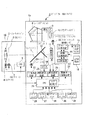
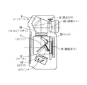
図1は、本発明によるディジタル一眼レフカメラの実施の形態を示す概略図、図2は、カメラ本体機構のレイアウトを説明するための断面図であり、両図には本発明に直接関連する部分のみが記載されている。
ディジタル一眼レフカメラ1は、カメラ本体1aと交換レンズ1bより構成され、交換レンズ1bのカメラ本体1aへの装着によって交換レンズ1b内のCPU6とカメラ本体1a内のCPU21は通信可能となる。
CPU6は、フォーカスレンズ2および絞り3をAFモータ4および絞りモータ5によってそれぞれ駆動制御する。
【0008】
図示しない被写体からの反射光は、交換レンズ1bを通りメインミラー7で反射してフォーカシングスクリーン34(図2参照)上に結像する。フォーカシングスクリーン34上の被写体像はペンタプリズム8で接眼レンズ32に導かれるとともに正立像に変換される。ペンタプリズム8を経由した被写体像の一部は測光センサ9に導かれる。光学ファインダ10に入射した被写体像はアイピースシャッタ11を通過して図示しない撮影者の目に入射する。光学ファインダ10の接眼レンズ32(図2参照)によって撮影者は被写体の正立虚像を観察することができる。
【0009】
一方、メインミラー7に入射する被写体光の一部はサブミラー12まで達し、該サブミラー12で下部に導かれAFモジュール内(図2参照)のAFセンサ19に入射する。測距演算装置20はAFセンサ19からの測距データに基づき被写体までの距離を演算する。CPU21は現在のレンズ位置と被写体までの距離からデフォーカス量を算出し、合焦位置までのレンズ駆動データを導き出し、このデータをCPU6に転送する。CPU6は転送データにしたがってAFモータ4を駆動制御しフォーカスレンズ2を合焦位置にもたらす。
【0010】
測光センサ9からの測光値は露出演算装置25に入力され、該露出演算装置25で露出値が演算される。CPU21はこの露出値によって適正露光量になるように絞り値を決定する。この絞り値データはCPU6に転送され、該CPU6は絞り3が決定された絞り値になるように絞りモータ5を駆動制御する。
通常の撮影では、CPU21はレリーズスイッチ26から撮影信号が入力すると、AEロック処理を行い、撮像素子13をオンしミラー駆動装置22を制御する。ミラー駆動装置22はミラーアップモータ23を駆動してメインミラー7および該メインミラーの裏側に配置されているサブミラー12をミラーボックス上部に退避させる。
【0011】
そしてシャッタ33(図2参照)を開放し、被写体光を撮像素子13上に結像させる。撮像素子制御装置24はCPU21の制御の基に適正露出対応のタイミング(シャッタ速度),ゲイン(ISO感度)を設定し撮像素子13に結像した画像データの電荷を読み出す制御を行う。撮像素子13はプログレッシブタイプのCCDであり、受光窓で受けた電荷は遮光部に移されてから電荷転送されるためシャッタ33が開いている状態でも転送中の光の影響を受けないものである。撮像素子13から読み出された画像データは画像処理装置14で所定の処理が行われ記憶装置17に転送される。記憶装置17はこの画像を一時蓄積し所定のファイル形式で記録媒体18に記録する。
画像処理装置14で処理された画像は、表示データ処理装置15にも送られ、表示用形式に変換処理され表示装置(LCD)16に表示される。
【0012】
撮影者は、この撮影画像を確認し、満足できる画像でない場合、削除することができる。削除は各種設定スイッチ31の操作により行うことができる。CPU21は各種設定スイッチ31より削除指示の信号を受信すると、表示装置16に表示されている撮影画像を記録媒体18より消去する。
なお、撮像素子13からの読み込みが行われると、シャッタ33は閉じ、メインミラー7およびサブミラー12は元の位置に復帰する。
【0013】
電子プレビュー機能を用いた撮影では、CPU21は電子プレビュースイッチ28からプレビュー信号が入力すると、アイピースシャッタ駆動モータ35を制御してアイピースシャッタ11を閉じる。その後、通常撮影と同様に測光センサ9,露出演算装置25により露出演算が行われ、CPU21は、その露出値のAEロック処理を行い撮像素子13をオンし、ミラー駆動装置22を制御してメインミラー7,サブミラー12を退避させシャッタ33の開処理を行う。
CPU21は、撮像素子制御装置24を制御してタイミング(シャッタ速度)およびゲイン(ISO感度)を設定する。
【0014】
そして結像された画像データの電荷を撮像素子13から読み出す制御を行う。撮像素子13から読み出された画像データは画像処理装置14で所定の処理が行われ表示データ処理装置15に送られ、表示用形式に変換処理され、表示装置(LCD)16に表示される。つぎに各種設定の読み込みを行い制御値を演算する。レリーズがなされず,プレビューがオフされない限り,この表示動作が例えば1秒間に3回繰り返される。
【0015】
電子プレビュー機能により、撮影者は、撮影する前に実際にシャッタ速度を順番に変えそれぞれのシャッタ速度での画像を観察することができるため、どのシャッタ速度が希望する画像であるかを予め確認できる。絞りについても順番に絞っていき、画像の焦点深度を確認し、希望する絞りを選択することが可能である。その他にホワイトバランス,露出補正量,プログラムシフト量,増幅率についても同様に確認することができる。
電子プレビュー状態でレリーズスイッチ信号が入力すると、タイミング,ゲイン設定を行い、撮像素子13から画像データを読み出し、画像処理装置14で所定の処理した後、記憶装置17を介して記録媒体18に画像を格納する。
【0016】
フォーカススイッチ27は、フォーカスボタンが押されたとき、フォーカス信号をCPU21に送出するものである。CPU21は測距演算装置20で演算された距離データからデフォーカス量を求め、CPU6を介してAFモータを駆動しフォーカスレンズ2を合焦位置にもたらす。
コマンドダイヤル30は、いわゆる電子ダイヤルで、後述の電子補正設定ボタン42,ISO設定ボタン43およびWB設定ボタン44と組み合わせて各設定などを選択するためのものである。
【0017】
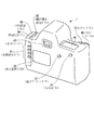
図3は、図1のディジタル一眼レフカメラのスイッチボタン類の配置を説明するための外観図である。
ディジタル一眼レフカメラ1の右上面にはカメラ情報を表示するLEDパネル46,レリーズボタン35が配置され、その前面側にはコマンドダイヤル45が設けられている。左上面には電子補正設定ボタン42,ISO設定ボタン43およびWB設定ボタン44が配置されている。電子補正設定ボタン42を押し、コマンドダイヤル45を操作することにより例えばEV値±0.3,±0.6,±1.0,±1.5・・・に調整可能である。ISO設定ボタン43を押し、コマンドダイヤル45を操作することにより例えばISO50,100,200,400,800・・・に調整可能である。WB設定ボタン44を押し、コマンドダイヤル45を操作することにより例えばAUTO,ストロボ光,蛍光光,8200K・・・に調整可能である。
【0018】
ディジタル一眼レフカメラ1の背面中央付近には表示装置(LCD)39が設けられ,その上部に光学ファインダ40が配置されている。
表示装置(LCD)39の右側には電子プレビューボタン37が配置されている。さらにその右上にフォーカスボタン36が配置されている。各種設定ボタン41は表示装置(LCD)39の左側に配置されている。
【0019】
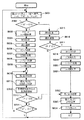
図4は、本発明によるディジタル一眼レフカメラの撮影動作を説明するためのフローチャートである。
以下、撮影シーケンスに従って電子プレビュー機能を用いた撮影と通常撮影の動作の流れを説明する。
撮影者は各種設定ボタン41を用いて露出モードを設定することができる。絞り優先,シャッタ優先,プログラム,マニュアルなどのモードである。絞り優先およびシャッタ優先モードの場合、絞りおよびシャッタ速度をそれぞれマニュアルで選択でき、電子プレビュー中に絞りおよびシャッタ速度を変更したときは、その変更した撮影画像を観察できる。プログラムモードの場合、電子プレビューであるときは、ロックしたAE値に併せてプログラムがシフトする。マニュアルモードの場合は、設定したシャッタ速度,絞りを反映した撮影画像がプレビューできる。
【0020】
CPU21はまず露出モードを読み込み(ステップ(以下「S」という)001)、電子プレビューボタンが押されたか否かを判断する(S002)。
電子プレビューボタン28が押された場合、アイピースシャッタを閉じる処理を行う(S003)。そして測光制御,露出演算を行った(S004,S005)後、AEロック処理を行う(S006)。
ついで、撮像素子オン処理,ミラーアップ処理,シャッタ開処理が行われる(S007〜S009)。
【0021】
CPU21の制御の下、撮像制御装置24は測定された適正露出に対するタイミング(シャッタ速度),ゲイン(ISO感度)を設定し(S010)、露光,転送,LCD表示処理を行う(S011)。つぎに各種設定(パラメータ)の読み込みを行う。例えば、シャッタ速度,絞り値,露出量補正,ISO感度,ホワイトバランスなどを読み込む。このプレビュー状態で、撮影者がパラメータの変更を行えば、その変更値が読み込まれ演算が行われる(S012)。パラメータ変更例としてシャッタ速度優先モードでシャッタ速度1/60秒,絞り8の状態にあった場合、シャッタ速度を1/125秒に変更すれば、絞り値は5.6になる。
【0022】
つぎにレリーズがオンしたか否か判断する(S013)。レリーズがオンであれば、S022〜S024によって撮影が行われる。レリーズがオフであれば,ついでプレビューがオフされたか否かを判断する(S014)。プレビューがオフされた場合には開始位置に戻る。プレビューがオフでない場合にはS010に移行する。レリーズがオフで,プレビューが解除されない限り、S010〜S14のループが繰り返し実行される。撮像素子は上述したようにプログレッシブ方式であるため、転送経路中で新たな電荷が加わわることはなく、誤差なく各画像の電荷を転送することができる。したがって、電子プレビュー中は撮影画像と同じ画像を観察でき、撮影条件を変えることもできる。
【0023】
一方、電子プレビューボタンが押されていない場合、測光制御,露出演算を行い(S015,S016)、つぎにレリーズボタン35が押されたか否か判断する(S017)。レリーズボタン35が押されていない場合、開始位置に戻る。レリーズボタン35が押された場合には、AEロック処理,撮像素子オン処理,ミラーアップ処理,シャッター開処理を行う(S018〜S021)。そしてタイミング,ゲイン設定を行い(S022)、露光後、シャッタを閉じ,転送,記録処理をして撮影画像を記録媒体18に格納する(S023,S024)。
【0024】
【発明の効果】
以上、説明したように本発明によれば、撮影前に撮影画像と同じ画像を繰り返し表示装置で観察でき、シャッタ速度,絞り,ゲイン,露出補正量,プログラムシフト量などの効果を画像として確認することができる。また、電子プレビュー開始時のAEロックした状態で撮影画像を表示装置に表示させることができる。さらにマニュアル露出モードで設定した条件での撮影画像の表示も可能である。
【図面の簡単な説明】
【図1】本発明によるディジタル一眼レフカメラの実施の形態を示す概略図である。
【図2】カメラ本体機構のレイアウトを説明するための断面図である。
【図3】図1のディジタル一眼レフカメラのスイッチボタン類の配置を説明するための外観図である。
【図4】本発明によるディジタル一眼レフカメラの撮影動作を説明するためのフローチャートである。
【符号の説明】
1 ディジタル一眼レフカメラ
2 フォーカスレンズ
3 絞り
4 AFモータ
5 絞りモータ
6,21 CPU
7 メインミラー
8 ペンタプリズム
9 測光センサ
10 光学ファインダ
11 アイピースシャッタ
12 サブミラー
13 撮像素子
14 画像処理装置
15 表示データ処理装置
16 表示装置(LCD)
17 記憶装置
18 記録媒体
19 AFセンサ
20 測距演算装置
22 ミラー駆動装置
23 ミラーアップモータ
24 撮像素子制御装置
25 露出演算装置
26 レリーズスイッチ
27 フォーカススイッチ
28 電子プレビュースイッチ
30 コマンドダイヤル(電子ダイヤル)
31 各種設定スイッチ[0001]
BACKGROUND OF THE INVENTION
The present invention relates to a digital single-lens reflex camera, and more particularly to a digital single-lens reflex camera having a preview function for confirming an image before photographing.
[0002]
[Prior art]
A conventional digital single-lens reflex camera cannot see changes in a photographed image due to differences in aperture, shutter speed, etc. before photographing. When confirming a photographed image, the photographed image is reproduced on the display device after photographing. If the reproduced image is different from the image imaged by the photographer, the recorded image can be reproduced in the same manner by discarding the image and changing the shutter speed, aperture, etc.
There is a preview function such as a silver halide single-lens reflex camera that can confirm how the captured image is captured before shooting, but this preview function is limited to the aperture value at the time of shooting and can only check the depth of focus . In addition, since this preview function reduces the amount of light by the aperture, it is difficult to confirm the detailed portion of the image.
[0003]
On the other hand, the method of reproducing and confirming a recorded image after shooting requires a playback operation after shooting, and there is a troublesome operation. Further, since the reproduction is performed after recording once, there is a problem that the storage area of the recording medium is consumed.
In addition to this, Patent Document 1 has been proposed as a method for confirming an image before photographing.
This proposal gives a function as a finder to the optical viewfinder and LCD image display unit in a single-lens reflex type electronic camera so that either of them can be selected. Then, the subject light enters the image sensor and is displayed on the LCD image display unit.
The LCD image display function of Patent Document 1 is for confirming whether or not the composition and arrangement of a subject are good, and displays an image obtained by thinning out pixels that is different from an actual captured image. For this reason, the same image as that actually taken cannot be confirmed on the LCD image display unit.
[Patent Document 1]
Japanese Patent Laid-Open No. 2001-2222059
[Problems to be solved by the invention]
An object of the present invention is to allow a digital single-lens reflex camera to confirm the same image as a captured image in advance by enabling the display unit to display the effect of the subject image due to a difference in shutter speed, aperture, etc. before shooting. It is to provide a digital single lens reflex camera.
[0005]
[Means for Solving the Problems]
In order to achieve the object, the invention according to claim 1 is an image pickup device, a photographing lens system that forms an image of reflected light of a subject on the image pickup device, and a display device that displays image data exposed to the image pickup device. An optical viewfinder for confirming a subject image at the time of photographing, and a reflection mirror system movable between a position for guiding reflected light of the subject to the optical viewfinder and a position for retracting to guide to the image sensor In the digital single-lens reflex camera, when the electronic preview is selected by the mode changeover switch means, the drive means for detecting the selection signal and driving the reflection mirror system to the retracted position when the mode changeover switch means is selected. In the retracted state of the reflection mirror system, the display device displays image data exposed to the image sensor under a predetermined exposure condition. Characterized in that it has and.
According to a second aspect of the present invention, in the digital single-lens reflex camera according to the first aspect, a subject light amount can be measured when the reflection mirror system is at a position for guiding reflected light of the subject to the optical viewfinder, and the reflection mirror A photometric device that becomes incapable of photometry when the system is moved to the retracted position, an exposure condition calculation device that calculates an exposure condition from a photometric value obtained from the photometric device, and an electronic preview selected by the mode changeover switch means Storage means for storing a photometric value obtained from the photometric device, and calculating the predetermined exposure condition from the photometric value stored in the storage means.
According to a third aspect of the present invention, in the digital single-lens reflex camera according to the second aspect, an eyepiece shutter that blocks external light from entering the eyepiece portion of the optical finder and the opening and closing of the eyepiece shutter. And the storage means stores the photometric value after at least one photometric operation has been performed after the eyepiece shutter is closed when the electronic preview is selected by the mode changeover switch means. It is characterized by that.
According to a fourth aspect of the present invention, in the digital single-lens reflex camera according to the first or second aspect of the present invention, the digital single-lens reflex camera includes a parameter changing unit that changes a parameter of an exposure condition. When the parameter is changed by the parameter changing means during the display, the exposure condition calculation device calculates the exposure condition using the changed parameter.
According to a fifth aspect of the present invention, in the digital single-lens reflex camera according to the fourth aspect, the exposure condition parameter is an exposure time, an aperture value, an exposure correction amount, a program shift amount, an amplification factor, or a white balance. To do.
According to a sixth aspect of the present invention, in the digital single-lens reflex camera according to the first aspect, there is provided means capable of setting a manual exposure mode, and when the manual exposure mode is set, the exposure set in the manual exposure mode. It is characterized by using conditions.
[0006]
[Action]
According to the above configuration, the same image as the photographed image can be repeatedly viewed on the display device before photographing, and effects such as shutter speed, aperture, gain, exposure correction amount, and program shift amount can be confirmed as an image. Further, it can be displayed on the display device in an AE locked state at the start of the electronic preview. Furthermore, manual exposure mode can also be set.
[0007]
DETAILED DESCRIPTION OF THE INVENTION
Hereinafter, embodiments of the present invention will be described in detail with reference to the drawings.
FIG. 1 is a schematic view showing an embodiment of a digital single-lens reflex camera according to the present invention, and FIG. 2 is a cross-sectional view for explaining the layout of the camera body mechanism, both of which are directly related to the present invention. Only listed.
The digital single-lens reflex camera 1 is composed of a
The CPU 6 controls the driving of the focus lens 2 and the diaphragm 3 by the
[0008]
Reflected light from a subject (not shown) passes through the interchangeable lens 1b and is reflected by the
[0009]
On the other hand, part of the subject light incident on the
[0010]
The photometric value from the photometric sensor 9 is input to the
In normal shooting, when a shooting signal is input from the
[0011]
Then, the shutter 33 (see FIG. 2) is opened, and the subject light is imaged on the image sensor 13. The image
The image processed by the
[0012]
The photographer can confirm the photographed image and delete it if the image is not satisfactory. Deletion can be performed by operating various setting switches 31. When the
When reading from the image sensor 13 is performed, the shutter 33 is closed and the
[0013]
In photographing using the electronic preview function, when a preview signal is input from the
The
[0014]
Then, control is performed to read out the charge of the imaged image data from the image sensor 13. Image data read from the image sensor 13 is subjected to predetermined processing by the
[0015]
The electronic preview function allows the photographer to check in advance which shutter speed is the desired image because the shutter speed can be actually changed in order before the image is taken and the images at the respective shutter speeds can be observed. . It is also possible to reduce the aperture in order, confirm the depth of focus of the image, and select the desired aperture. In addition, the white balance, exposure correction amount, program shift amount, and amplification factor can be confirmed in the same manner.
When a release switch signal is input in the electronic preview state, timing and gain are set, image data is read from the image sensor 13, subjected to predetermined processing by the
[0016]
The
The
[0017]
FIG. 3 is an external view for explaining the arrangement of switch buttons of the digital single-lens reflex camera of FIG.
An
[0018]
A display device (LCD) 39 is provided near the center of the back surface of the digital single-lens reflex camera 1, and an optical viewfinder 40 is disposed on the display device (LCD) 39.
On the right side of the display device (LCD) 39, an
[0019]
FIG. 4 is a flowchart for explaining the photographing operation of the digital single lens reflex camera according to the present invention.
Hereinafter, the flow of operations using the electronic preview function and normal shooting according to the shooting sequence will be described.
The photographer can set the exposure mode using various setting buttons 41. Aperture priority, shutter priority, program, manual, etc. modes. In the aperture priority mode and the shutter priority mode, the aperture and shutter speed can be selected manually, and when the aperture and shutter speed are changed during electronic preview, the changed captured image can be observed. In the case of the program mode, in the electronic preview, the program shifts in accordance with the locked AE value. In the manual mode, a shot image reflecting the set shutter speed and aperture can be previewed.
[0020]
The
When the
Next, image sensor ON processing, mirror up processing, and shutter opening processing are performed (S007 to S009).
[0021]
Under the control of the
[0022]
Next, it is determined whether or not the release is turned on (S013). If the release is on, shooting is performed in S022 to S024. If the release is off, then it is determined whether the preview is off (S014). If the preview is turned off, it returns to the start position. If the preview is not off, the process proceeds to S010. Unless the release is off and the preview is not canceled, the loop of S010 to S14 is repeatedly executed. As described above, since the image sensor is a progressive method, a new charge is not added in the transfer path, and the charge of each image can be transferred without error. Therefore, during the electronic preview, the same image as the captured image can be observed, and the shooting conditions can be changed.
[0023]
On the other hand, if the electronic preview button is not pressed, photometry control and exposure calculation are performed (S015, S016), and it is then determined whether the release button 35 is pressed (S017). When the release button 35 is not pressed, the process returns to the start position. When the release button 35 is pressed, AE lock processing, image sensor on processing, mirror up processing, and shutter opening processing are performed (S018 to S021). Then, the timing and gain are set (S022), and after exposure, the shutter is closed, the transfer and recording processes are performed, and the photographed image is stored in the recording medium 18 (S023, S024).
[0024]
【The invention's effect】
As described above, according to the present invention, the same image as the photographed image can be repeatedly observed on the display device before photographing, and effects such as shutter speed, aperture, gain, exposure correction amount, and program shift amount are confirmed as an image. be able to. In addition, the captured image can be displayed on the display device in an AE locked state at the start of the electronic preview. Furthermore, it is possible to display a photographed image under the conditions set in the manual exposure mode.
[Brief description of the drawings]
FIG. 1 is a schematic view showing an embodiment of a digital single-lens reflex camera according to the present invention.
FIG. 2 is a cross-sectional view for explaining a layout of a camera body mechanism.
3 is an external view for explaining an arrangement of switch buttons of the digital single-lens reflex camera of FIG. 1. FIG.
FIG. 4 is a flowchart for explaining a photographing operation of the digital single-lens reflex camera according to the present invention.
[Explanation of symbols]
DESCRIPTION OF SYMBOLS 1 Digital single-lens reflex camera 2 Focus lens 3
7 Main mirror 8 Penta prism 9 Photometric sensor 10 Optical viewfinder 11
31 Various setting switches
Claims (6)
モード切替スイッチ手段を有し、
前記モード切替スイッチ手段により電子プレビューが選択された場合、その選択信号を検知して前記反射ミラー系を前記退避位置まで駆動する駆動手段と、
前記反射ミラー系の前記退避状態において、所定の露光条件により前記撮像素子に露光された画像データを、前記表示装置に表示する手段と、
を有することを特徴とするディジタル一眼レフカメラ。An image sensor, a display device that displays image data exposed to the image sensor, an optical finder for confirming a subject image at the time of shooting, a position for guiding reflected light of the subject to the optical finder, and the imaging In a digital single-lens reflex camera provided with a reflective mirror system that can move between a retracted position for guiding to an element,
Having mode changeover switch means,
When electronic preview is selected by the mode changeover switch means, driving means for detecting the selection signal and driving the reflection mirror system to the retracted position;
Means for displaying, on the display device, image data exposed to the imaging device under a predetermined exposure condition in the retracted state of the reflecting mirror system;
A digital single-lens reflex camera characterized by comprising:
前記反射ミラー系が前記被写体の反射光を前記光学ファインダに導く位置にあるとき被写体光量が測定可能で、前記反射ミラー系が退避位置に移動したとき測光不能となる測光装置と、
前記測光装置から得られた測光値から露光条件を算出する露光条件演算装置と、
前記モード切替スイッチ手段により電子プレビューが選択されたとき前記測光装置から得られた測光値を記憶する記憶手段とを備え、
前記記憶手段に記憶された測光値によって前記所定の露光条件を算出することを特徴とするディジタル一眼レフカメラ。The digital single-lens reflex camera according to claim 1,
A photometric device capable of measuring a subject light amount when the reflecting mirror system is at a position for guiding reflected light of the subject to the optical viewfinder, and disabling photometry when the reflecting mirror system is moved to a retracted position;
An exposure condition calculation device for calculating an exposure condition from a photometric value obtained from the photometric device;
Storage means for storing a photometric value obtained from the photometric device when an electronic preview is selected by the mode changeover switch means;
The digital single-lens reflex camera characterized in that the predetermined exposure condition is calculated from a photometric value stored in the storage means.
前記光学ファインダの接眼部分に外光が該光学ファインダ内に入射することを阻止するアイピースシャッタと、
前記アイピースシャッタの開閉を駆動する駆動装置を備え、
前記記憶手段は前記モード切替スイッチ手段により電子プレビューが選択されたとき前記アイピースシャッタが閉じてから少なくとも1回以上の測光動作が行われた後にその測光値を記憶することを特徴とするディジタル一眼レフカメラ。The digital single-lens reflex camera according to claim 2,
An eyepiece shutter that prevents outside light from entering the eyepiece portion of the optical viewfinder;
A driving device for driving opening and closing of the eyepiece shutter;
The storage unit stores a photometric value after at least one photometric operation is performed after the eyepiece shutter is closed when an electronic preview is selected by the mode changeover switch unit. camera.
露光条件のパラメータを変更するパラメータ変更手段を有し、
露光された画像データを所定の間隔で前記表示装置に表示する間に前記パラメータ変更手段によりパラメータが変更された場合、該変更されたパラメータで前記露光条件演算装置により露光条件を演算することを特徴とするディジタル一眼レフカメラ。The digital single-lens reflex camera according to claim 1 or 2,
Having parameter changing means for changing parameters of exposure conditions;
When the parameter is changed by the parameter changing unit while the exposed image data is displayed on the display device at a predetermined interval, the exposure condition calculation device calculates the exposure condition using the changed parameter. A digital single-lens reflex camera.
前記露光条件のパラメータは、露光時間,絞り値,露出補正量,プログラムシフト量,増幅率またはホワイトバランスであること特徴とするディジタル一眼レフカメラ。The digital single-lens reflex camera according to claim 4,
The digital single-lens reflex camera according to claim 1, wherein the parameter of the exposure condition is exposure time, aperture value, exposure correction amount, program shift amount, amplification factor, or white balance.
マニュアル露出モードを設定可能な手段を有し、
前記マニュアル露出モードが設定された場合、該マニュアル露出モードで設定された露光条件を用いることを特徴とするディジタル一眼レフカメラ。The digital single-lens reflex camera according to claim 1,
It has means that can set the manual exposure mode,
A digital single-lens reflex camera using the exposure condition set in the manual exposure mode when the manual exposure mode is set.
Priority Applications (1)
| Application Number | Priority Date | Filing Date | Title |
|---|---|---|---|
| JP2003176834A JP2005010643A (en) | 2003-06-20 | 2003-06-20 | Digital single-lens reflex camera |
Applications Claiming Priority (1)
| Application Number | Priority Date | Filing Date | Title |
|---|---|---|---|
| JP2003176834A JP2005010643A (en) | 2003-06-20 | 2003-06-20 | Digital single-lens reflex camera |
Publications (1)
| Publication Number | Publication Date |
|---|---|
| JP2005010643A true JP2005010643A (en) | 2005-01-13 |
Family
ID=34099598
Family Applications (1)
| Application Number | Title | Priority Date | Filing Date |
|---|---|---|---|
| JP2003176834A Pending JP2005010643A (en) | 2003-06-20 | 2003-06-20 | Digital single-lens reflex camera |
Country Status (1)
| Country | Link |
|---|---|
| JP (1) | JP2005010643A (en) |
Cited By (8)
| Publication number | Priority date | Publication date | Assignee | Title |
|---|---|---|---|---|
| US7440692B2 (en) | 2005-05-20 | 2008-10-21 | Olympus Imaging Corp. | Digital camera |
| JP2009111844A (en) * | 2007-10-31 | 2009-05-21 | Fujifilm Corp | Imaging device |
| US7583892B2 (en) | 2005-06-08 | 2009-09-01 | Olympus Imaging Corp. | Finder device and camera |
| US20090262207A1 (en) * | 2006-06-20 | 2009-10-22 | Naoto Yumiki | Camera system |
| US7609960B2 (en) | 2005-05-31 | 2009-10-27 | Olympus Imaging Corp. | Finder device and camera |
| JP2012244532A (en) * | 2011-05-23 | 2012-12-10 | Canon Inc | Imaging apparatus and control method |
| US8345141B2 (en) | 2005-12-07 | 2013-01-01 | Panasonic Corporation | Camera system, camera body, interchangeable lens unit, and imaging method |
| KR101533275B1 (en) * | 2008-06-17 | 2015-07-02 | 삼성전자주식회사 | Photographing apparatus |
-
2003
- 2003-06-20 JP JP2003176834A patent/JP2005010643A/en active Pending
Cited By (12)
| Publication number | Priority date | Publication date | Assignee | Title |
|---|---|---|---|---|
| US7440692B2 (en) | 2005-05-20 | 2008-10-21 | Olympus Imaging Corp. | Digital camera |
| US7609960B2 (en) | 2005-05-31 | 2009-10-27 | Olympus Imaging Corp. | Finder device and camera |
| US7583892B2 (en) | 2005-06-08 | 2009-09-01 | Olympus Imaging Corp. | Finder device and camera |
| US8345141B2 (en) | 2005-12-07 | 2013-01-01 | Panasonic Corporation | Camera system, camera body, interchangeable lens unit, and imaging method |
| US20090262207A1 (en) * | 2006-06-20 | 2009-10-22 | Naoto Yumiki | Camera system |
| CN102062989A (en) * | 2006-06-20 | 2011-05-18 | 松下电器产业株式会社 | Camera system |
| JP2012124915A (en) * | 2006-06-20 | 2012-06-28 | Panasonic Corp | Camera system |
| US9007507B2 (en) | 2006-06-20 | 2015-04-14 | Panasonic Intellectual Property Management Co., Ltd. | Camera system for adjusting displayed image according to an aperture value |
| JP2009111844A (en) * | 2007-10-31 | 2009-05-21 | Fujifilm Corp | Imaging device |
| US8130308B2 (en) | 2007-10-31 | 2012-03-06 | Fujifilm Corporation | Image capture device capable of improved image capturing in electronic viewfinder mode |
| KR101533275B1 (en) * | 2008-06-17 | 2015-07-02 | 삼성전자주식회사 | Photographing apparatus |
| JP2012244532A (en) * | 2011-05-23 | 2012-12-10 | Canon Inc | Imaging apparatus and control method |
Similar Documents
| Publication | Publication Date | Title |
|---|---|---|
| US7872684B2 (en) | Camera capable of correcting information for focusing control, using information stored in storage section of mounted lens apparatus | |
| US8035726B2 (en) | Digital camera and focus control method | |
| JP4235424B2 (en) | Camera and camera system | |
| JP4395334B2 (en) | Digital camera | |
| JP2005010643A (en) | Digital single-lens reflex camera | |
| JP2008242230A (en) | Imaging apparatus, imaging system, and imaging method | |
| CN101473641A (en) | Camera system | |
| JP4060953B2 (en) | Electronic camera | |
| JP2000047315A (en) | Camera | |
| JP2010136097A (en) | Camera apparatus and camera system | |
| JP2010147612A (en) | Camera and camera system | |
| JPH0654253A (en) | camera | |
| JP2004109831A (en) | Optical equipment | |
| JP2005033393A (en) | Digital single-lens reflex camera | |
| JP2904736B2 (en) | Video camera with integrated still camera | |
| JPH11231409A (en) | Camera used for silver-salt photographing and also electronic image pickup | |
| JP3420996B2 (en) | camera | |
| JPH08248510A (en) | Automatic focusing device for compound camera | |
| JP5463657B2 (en) | camera | |
| JP2852223B2 (en) | Video camera with integrated still camera | |
| JPH0436508B2 (en) | ||
| JPH08251466A (en) | Automatic focusing device for compound camera | |
| JP4780877B2 (en) | Electronic camera and control method | |
| JP2005045393A (en) | Digital single-lens reflex camera | |
| JP2005136654A (en) | camera |
Legal Events
| Date | Code | Title | Description |
|---|---|---|---|
| A621 | Written request for application examination |
Free format text: JAPANESE INTERMEDIATE CODE: A621 Effective date: 20051214 |
|
| A131 | Notification of reasons for refusal |
Free format text: JAPANESE INTERMEDIATE CODE: A131 Effective date: 20081224 |
|
| A521 | Request for written amendment filed |
Free format text: JAPANESE INTERMEDIATE CODE: A523 Effective date: 20090216 |
|
| A521 | Request for written amendment filed |
Free format text: JAPANESE INTERMEDIATE CODE: A523 Effective date: 20090216 |
|
| A131 | Notification of reasons for refusal |
Free format text: JAPANESE INTERMEDIATE CODE: A131 Effective date: 20090512 |
|
| A521 | Request for written amendment filed |
Free format text: JAPANESE INTERMEDIATE CODE: A523 Effective date: 20090708 |
|
| A02 | Decision of refusal |
Free format text: JAPANESE INTERMEDIATE CODE: A02 Effective date: 20090804 |