JP2005006188A - Crc computation method and crc computing unit - Google Patents
Crc computation method and crc computing unit Download PDFInfo
- Publication number
- JP2005006188A JP2005006188A JP2003169574A JP2003169574A JP2005006188A JP 2005006188 A JP2005006188 A JP 2005006188A JP 2003169574 A JP2003169574 A JP 2003169574A JP 2003169574 A JP2003169574 A JP 2003169574A JP 2005006188 A JP2005006188 A JP 2005006188A
- Authority
- JP
- Japan
- Prior art keywords
- crc
- division
- polynomial
- multiplication
- remainder
- Prior art date
- Legal status (The legal status is an assumption and is not a legal conclusion. Google has not performed a legal analysis and makes no representation as to the accuracy of the status listed.)
- Abandoned
Links
Images


Landscapes
- Detection And Correction Of Errors (AREA)
- Error Detection And Correction (AREA)
Abstract
Description
【0001】
【発明の属する技術分野】
この発明は、デジタル情報の誤りを検出するCRC(Cyclic Redundancy Check)演算に関するCRC演算方法およびCRC演算装置に関する。
【0002】
【従来の技術】
CRC符号は、情報系列i(x)の生成多項式g(x)による剰余を情報系列に付加して生成する。nビットのCRC検査ビットを付加するにはn次の生成多項式g(x)を用意し、i(x)のg(x)による剰余v(x)を求め、v(x)を検査ビットとして付加する。
【0003】
誤り検出を行う場合には、i(x)・xn+v(x)に対応する受信多項式f(x)の生成多項式g(x)による剰余z(x)を求める。受信多項式r(x)に誤りがなければ、r(x)=i(x)・xn+v(x)は生成多項式g(x)で割り切れて、剰余z(x)は0となり、誤りがあれば割り切れず0とならないことから、誤りを検出することが可能となる(例えば、非特許文献1参照)。
【0004】
CRC検査ビット生成および検査を行うCRC演算は生成多項式に基づく除算であるから、シフトレジスタを用いて構成することができる。また、データ多項式を複数ビットずつ並列に読み出し、演算することで演算を高速化することが可能である。
【0005】
従来のCRC演算の並列化による高速化方法が、特許文献1に記載されている。その基本的な演算方法は、並列入力したデータに対し予めデータ多項式の次数を調整するべき乗を乗じ、その結果を除算して、剰余を加算することで並列化を実現している。例えば、多項式を式(1)で展開し、f1(x)およびf3(x)にx32を乗算しておいて、夫々の生成多項式g(x)による剰余を求め、夫々を加算する。予め乗算をしてから除算を行うことに特徴がある。
【数1】

【非特許文献1】
「符号理論」電子情報通信学会(p.118)
【特許文献1】
特開平8−330976号公報
【0007】
【発明が解決しようとする課題】
従来のCRC演算は、受信多項式を高次より順に除算回路へ入力していくために、処理するのに符号長分のステップ数を要し、遅延時間が大きいという問題があった。また、複数ある受信多項式ブロックに対し除算を行う場合に、受信多項式の高次から除算を行う必要があるため、低次の受信多項式ブロックは高次の演算が終了しなければ開始できない。そのため、受信信号に対するCRC演算を行う処理遅延は、全符号に対する除算分だけ要していた。
【0008】
そこで、CRC演算を並列化し演算を高速化する方法が提案されているが、受信多項式ブロックに予め乗算してから除算処理を行う方法であって、並列化した1ブロックが大きくなる場合に、メモリ等の制約からデータに乗算を行うことが困難であることから、分割する1ブロックの大きさに制限が加わり、1ブロックの大きさが変化する場合などに対応することも困難である。逆に1ブロックを小さくした場合には、符号長が長い場合に並列化数が増え、回路規模が大きくなってしまう。また、CRC演算を行う多項式が1ビットずつ並列に入力される場合などは、読み出すデータ・サイズ単位まで情報を保持する必要もある。
【0009】
また、ターボ符号とCRC符号の連接符号を用い、複数の受信多項式がある場合に、ターボ復号演算の最後にデータ多項式の並べ替えをする必要があり、全データに対する復号が完了しなければCRC演算を開始できない。仮に復号順序を入れ替えたターボ復号を適用したとしても、受信多項式が複数ある場合には低次の受信多項式に対する除算は高次の演算終了を待たなければならず、全符号に対する除算分だけの処理時間を要するという課題があった。
【0010】
この発明は以上のような課題を解消するためになされたもので、並列入力されるデータに対するCRC生成多項式に基づく除算操作を、夫々の入力データに並列に行った後、次数調整の乗算と加算を行うことで演算の高速化を図ることを目的とする。
【0011】
【課題を解決するための手段】
この発明に係るCRC演算方法では、受信多項式が複数ブロックに分割されて並列に入力され、CRCの生成多項式に基づいた除算操作を夫々の受信多項式に対し並列に行い、当該除算操作の結果に受信多項式ブロックの次数を調整する乗算を行った後、当該乗算結果の夫々を加算し、受信多項式に対するCRC結果を得るものである。
【0012】
この発明に係るCRC演算方法では、受信多項式を複数の受信多項式ブロックに分割して、CRCの生成多項式に基づいた除算操作を並列に行い、当該除算操作の結果に受信多項式ブロックの次数を調整する乗算を行った後、当該乗算結果の夫々を加算して、全受信多項式に対するCRC結果を得るものである。
【0013】
この発明に係るCRC演算装置では、並列に入力される受信データに対応して、CRCの生成多項式に基づいた複数の除算回路と、剰余の次数を調整する乗算を行う乗算器と、加算を行う加算器とを備えるものである。
【0014】
この発明に係るCRC演算方法は、情報系列が複数ブロックに分割されて並列に入力され、CRCの生成多項式に基づいた除算操作を夫々の情報系列ブロックに対し並列に行い、当該除算操作の結果に情報系列ブロックの次数を調整する乗算を行った後、当該乗算結果の夫々を加算し、CRC検査ビットを生成するものである。
【0015】
この発明に係るCRC演算方法は、情報系列を複数ブロックに分割して、CRCの生成多項式に基づいた除算操作を並列に行い、当該除算操作の剰余に各ブロックの次数を合わせる乗算と加算を行うことで、CRC検査ビットを得るものである。
【0016】
この発明に係るCRC演算装置は、情報系列を複数ブロックに分割する分割処理手段と、CRCの生成多項式に基づいた複数の除算手段と、剰余の次数を調整する乗算を行う乗算手段と、前記乗算手段による乗算結果の加算を行う加算手段とを備えるものである。
【0017】
【発明の実施の形態】
以下、この発明の実施の一形態を説明する。
実施の形態1.
この発明に係る実施の形態1について、図1および図2を参照して説明する。なお、図1は実施の形態1に係るCRC演算装置1の回路構成を示す図であり、図2はこのCRC演算装置1の動作を示すブロック図である。
【0018】
この発明のCRC演算方法によるCRC演算の並列化は、以下に示す多項式の除算方法に基づいている。CRC演算で求めるべき値は多項式f(x)に対する生成多項式g(x)による剰余z(x)であり、式(2)で表すことができる。
【数2】
【数3】
式(3)は多項式f(x)をm分割したと見ることもでき、分割された1ブロックの大きさはNである。さらに、多項式ブロックfi(x)とべき乗xNの生成多項式g(x)による剰余を式(4)、式(5)で表すと
【数4】
【数6】
式(7)より、分割した多項式ブロックの各剰余zi(x)に次数を調整するy(x)の乗算を行い、それらを加算すれば、全多項式f(x)の生成多項式g(x)の剰余z(x)を得ることがわかる。
【0021】
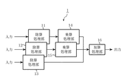
つぎに、上述したことをCRC演算に適用し、具体例について述べる。実施の形態1は並列入力した受信データに対し、除算を並列に行うことを目的としている。図1に示すCRC演算装置1は、受信多項式の入力が3つ並列した場合の構成例で、入力した各受信多項式に対し、CRC生成多項式に基づいた除算を行う除算処理部11、12、13、夫々の除算結果である剰余に対し、受信多項式の次数を調整する乗算を行う乗算処理部14、15、次数調整を行った剰余の加算を行う加算処理部16を備えている。
【0022】
実施の形態1のCRC演算装置1は、入力された複数の受信多項式ブロックに対し、夫々に並列に除算処理を行い、その結果に乗算および加算を行うことで、CRC演算結果を得るCRC演算装置である。なお、各除算処理部11〜13を構成する除算回路はシフトレジスタで構成し、乗算処理部14、15を構成する乗算器は排他的論理和回路を用いた生成多項式を法とするGF(2)上の乗算回路を備えている。
【0023】
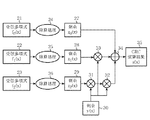
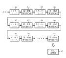
次にCRC演算装置1の動作について説明する。図2はCRC演算装置1の動作を示すブロック図であり、例として符号が3分割されている場合を示している。この動作は大略次の4つの行程で行われる。
【0024】
第一行程.
分割された受信多項式f0(x)21、f1(x)22、f2(x)23を、本CRC演算装置1に並列に入力する。各受信多項式f0(x)21、f1(x)22、f2(x)23と、全受信多項式の関係は式(3)で表されるものである。
【0025】
第二行程.
各受信多項式f0(x)21、f1(x)22、f2(x)23を夫々の高次から順に除算回路に入力することで、除算処理24、25、26を並列に行う。各受信多項式ブロックのデータを全て入力し終えた時点で、各除算処理24〜25の回路を構成するシフトレジスタの状態は、各ブロックの生成多項式g(x)による剰余を示しており、結果は式(4)で示す剰余zi(x)〔z0(x)27、z1(x)28、z2(x)29〕として読み出す。
【0026】
第三行程.
第二行程で求めた剰余zi(x)に対し、次数を合わせるためにy(x)30との乗算処理31、32、33を式(7)に従って行う。y(x)30は受信多項式の1ブロックの大きさNが決まれば求めることができるので、予め計算しておく。
【0027】
本来、シフトレジスタでfi(x)・xi・Nの生成多項式g(x)による剰余を求める場合に、(i+1)N回のクロックを要するが、第二行程の演算ではN回分の演算しか行っていないため、剰余zi(x)は要求している次数まで除算が進んでいない。そこで、xNの生成多項式g(x)による剰余である、式(5)に示すy(x)30を、生成多項式g(x)を法としてGF(2)上で、剰余zi(x)に乗算することで、シフトレジスタによる残りの演算をした結果と同じ結果を得ることができる。シフトレジスタによる演算がi・N回足りなければy(x)30を剰余zi(x)にi回乗算することで、すべての次数を調整することができる。
【0028】
第四行程.
最後に、第三行程で行ったすべての乗算の結果を、式(7)に示すように加算処理34を行えば、式(2)に示すCRC演算結果35であるz(x)を得ることができる。
【0029】
以上説明したように、この実施の形態1によれば、除算処理を分割して並列に行うことにより、低次の受信多項式ブロックは高次ブロックの除算の終了を待つ必要がなく、処理を高速化し、各復号において受信多項式が高次より順に出力されるならば、各結果を逐次除算回路に入力することで、復号と同時にCRC演算を行うことも可能にする効果がある。
【0030】
また、各受信多項式ブロックに対し、先に除算を行ってから乗算を行うために、乗算は生成多項式の次数未満の多項式の乗算となり、各受信多項式ブロックの大きさが大きい場合や変化する場合などにも大きなメモリや回路を必要とせず、回路規模を小さくできる効果がある。
【0031】
実施の形態2.
この発明に係る実施の形態2について、図3および図4を参照して説明する。なお、図3は実施の形態2に係るCRC演算装置2の回路構成を示す図であり、図4はこのCRC演算装置2の動作を示すブロック図である。
【0032】
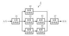
実施の形態2は実施の形態1とは異なり、受信多項式を分割することでCRC演算を並列化することを目的としている。図3は実施の形態2のCRC演算装置2を示しており、受信多項式を3分割した場合の構成例である。受信多項式を式(3)に従って複数ブロックに分割する分割処理部41と、CRC生成多項式に基づいた除算を行う除算処理部42、43、44と、除算結果である剰余に対し、次数調整の乗算を行う乗算処理部45、46と、それらの加算を行う加算処理部47を備えている。実施の形態2は、入力された受信多項式を複数ブロックに分割し、夫々に除算処理を行い、結果に乗算および加算を行うことで、CRC結果を得るCRC演算装置である。
【0033】
なお、受信多項式を分割する際にはメモリから読み出すアドレスを分割に応じて制御し、各除算処理部42〜44の除算回路はシフトレジスタで構成し、乗算器は排他的論理和回路を用いた生成多項式を法とするGF(2)上の乗算回路を備えている。
【0034】
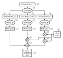
次にCRC演算装置2の動作について説明する。図4はCRC演算装置2の動作を示すブロック図であり、例として符号が3分割されている場合を示している。この動作は大略次の5つの行程で行われる。
【0035】
第一行程.
複数の除算回路を備えた装置に受信多項式f(x)51を入力し、除算回路の個数と同数となるように式(3)に応じて分割処理52をする。
【0036】
第二行程.
分割された受信多項式f0(x)53、f1(x)54、f2(x)55を、夫々の除算回路に並列に入力する。
【0037】
第三行程.
各受信多項式f0(x)53、f1(x)54、f2(x)55を夫々の高次から順に除算回路に入力することで、各除算処理56、57、58を並列に行う。各受信多項式ブロックのデータを全て入力し終えた時点で、各除算処理56〜58の回路を構成するシフトレジスタの状態は、各ブロックの生成多項式g(x)による剰余を示しており、結果は式(4)で示す剰余zi(x)〔z0(x)59、z1(x)60、z2(x)61〕として読み出す。
【0038】
第四行程.
第三行程で求めた剰余zi(x)に対し、次数を合わせるためにy(x)62との乗算処理63、64、65を式(7)に従って行う。y(x)62は受信多項式の1ブロックの大きさNが決まれば求めることができるので、予め計算しておく。
【0039】
本来、シフトレジスタでfi(x)・xi・Nの生成多項式g(x)による剰余を求める場合に、(i+1)N回のクロックを要するが、第三行程の演算ではN回分の演算しか行っていないため、剰余zi(x)は要求している次数まで除算が進んでいない。そこで、xNの生成多項式g(x)による剰余である、式(5)に示すy(x)62を、生成多項式g(x)を法としてGF(2)上で、剰余zi(x)に乗算することで、シフトレジスタによる残りの演算をした結果と同じ結果を得ることができる。シフトレジスタによる演算がi・N回足りなければy(x)62を剰余zi(x)にi回乗算することで、すべての次数を調整することができる。
【0040】
第五行程.
最後に、第四行程で行ったすべての乗算の結果を、式(7)に示すように加算処理66を行えば、式(2)に示すCRC演算結果67であるz(x)を得ることができる。
【0041】
以上説明したように、この実施の形態2によれば、入力された受信多項式を分割して除算を行い、分割された低次の受信多項式ブロックに関するCRC演算を高次の演算が終わるのを待つ必要がないことから、演算を高速処理できる効果がある。
【0042】
実施の形態3.
この発明に係る実施の形態3について、図5〜図7を参照して説明する。なお、図5は実施の形態3に係るCRC演算装置3の回路構成を示す図であり、図6はこのCRC演算装置3で用いるターボ復号部の構成を示す図であり、図7はこのCRC演算装置3の動作を示す図である。
【0043】
実施の形態3のCRC演算装置3は、複数ある受信系列に対しターボ復号を並列に行って、その後CRCで残留誤りを検出する場合に演算の高速化を目的としている。図5はCRC演算装置3の構成図で、2つに並列化した場合を例に示しており、ターボ復号を行うターボ復号部71、72と、CRC生成多項式に基づく除算を行う除算処理部73、74と、各除算結果に次数調整の乗算を行う乗算処理部75と、それらの加算を行う加算処理部76を備えている。
【0044】
なお、除算処理部73、74を構成する除算回路はシフトレジスタで構成し、乗算器は排他的論理和回路を用いた生成多項式を法とするGF(2)上の乗算回路を備えている。
【0045】
また、ターボ復号には復号演算順序を入れ替えたターボ復号方法を用いれば、さらに高速に演算処理することができる。順序を入れ替えたターボ復号とは、インターリーブした受信系列の尤度を計算する第二要素復号器の演算を先に、インターリーブしていない受信系列の尤度を計算する第一要素復号器の演算を後から行い、各要素復号器における情報ビット数nに対するパスメトリック計算を、時点nから1に向かう後向きパスメトリック計算を先に、時点1からnに向かう前向きパスメトリック計算を後から行うターボ復号方法である。
【0046】
このターボ復号方法は、図6に示す通り、まず、入力データをインターリーバ81でインターリーブしてから第二要素復号器84で復号し、次にデインターリーバ87でデインターリーブして第一要素復号器89で復号する。この処理を第一要素復号器91まで行うことで、ターボ復号の繰り返し演算の最終回がインターリーブされていない状態の時点1からnに向かってパスメトリックを計算するために、復号結果が受信多項式の高次より出力されることである。こうすることで、復号結果は受信多項式の高次より降順に出力されることとなり、結果を随時CRC演算部92へ入力することが可能となる。
【0047】
なお、図6において、第二要素復号器84〜86の記号「%」はインターリーブした系列の復号処理を表し、第一要素復号器89〜91の記号「♯」はインターリーブされていない系列の復号処理を表し、記号「%」および「♯」に続く数字はターボ復号繰り返し数を表す。例えば♯2はターボ復号繰り返しが2回目で、インターリーブされていない系列の復号処理を表している。
【0048】
次にCRC演算装置3の動作について説明する。図7はCRC演算装置3の動作を示すブロック図であり、例として2分割されている場合を示している。この動作は大略次の4つの行程で行われる。
【0049】
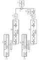
第一行程.
受信系列を第一ターボ復号器101、および第二ターボ復号器102に入力して、並列に復号を行う。順序を入れ替えたターボ復号方法を用いている場合には、復号結果は受信多項式f0(x)103、f1(x)104の高次より降順に復号結果が1ビットずつ出力される。
【0050】
第二行程.
第一行程で高次より1ビットずつ出力される受信多項式f0(x)103、f1(x)104を夫々除算回路105、除算回路106に随時、入力することで、各除算を並列処理する。さらにターボ復号結果をすぐに除算回路に入力することから、ターボ復号の最終回と除算も並列化することができる。ターボ復号が終わり、各受信多項式ブロックを全て入力し終えた時点で、各除算回路105、106を構成するシフトレジスタの状態は、各ブロックの生成多項式g(x)による剰余を示している。つぎに式(4)に示す剰余zi(x)〔z0(x)107、z1(x)108〕を読み出す。
【0051】
第三行程.
第二行程で求めた剰余zi(x)に対し、次数を合わせるためにy(x)109との乗算処理110を式(7)に従って行う。y(x)109は受信多項式の1ブロックの大きさNが決まれば求めることができるので、予め計算しておく。
【0052】
本来、シフトレジスタでfi(x)・xi・Nの生成多項式g(x)による剰余を求める場合に、(i+1)N回のクロックを要するが、第二行程の演算ではN回分の演算しか行っていないため、剰余zi(x)は要求している次数まで除算が進んでいない。そこで、xNの生成多項式g(x)による剰余である、式(5)に示すy(x)109を、生成多項式g(x)を法としてGF(2)上で、剰余zi(x)に乗算することで、シフトレジスタによる残りの演算をした結果と同じ結果を得ることができる。シフトレジスタによる演算がi・N回足りなければy(x)109を剰余zi(x)にi回乗算することで、すべての次数を調整することができる。
【0053】
第四行程.
最後に、第三行程で行ったすべての乗算の結果を、式(7)に示すように加算処理111を行えば、式(2)に示すCRC演算結果112であるz(x)を得ることができる。
【0054】
以上説明したように、この実施の形態3によれば、並列化したCRC演算と復号順序を入れ替えたターボ復号方法を組み合わせることで、複数入力の受信多項式に対し、ターボ復号最終回のインターリーブしていない場合の復号とCRC演算が同時に行えることになり、CRC演算による遅延時間を大幅に削減可能で、ターボ復号終了後、次数調整の乗算と加算による遅延時間のみでCRC結果を得ることができ、演算を高速処理できる効果がある。
【0055】
実施の形態4.
この発明に係る実施の形態4について、図8〜図10を参照して説明する。なお、図8は実施の形態4に係るCRC演算装置4の構成を示すブロック図であり、図9は図8に示すCRC結果算出部の構成を示す図であり、図10はこのCRC演算装置4の動作の流れを示すフローチャートである。
【0056】
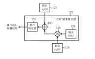
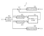
実施の形態4のCRC演算装置4は、図8および図9に示すように、複数ある受信系列に対しターボ復号を並列に行いながらCRC演算を行い、ターボ復号繰り返し回数を制御する場合である。CRC演算装置4は2つに並列化した場合を例に示しており、ターボ復号を行う第一ターボ復号器121、および第二ターボ復号器122で構成する。また、第一ターボ復号器121の出力からCRC生成多項式に基づいて剰余z0(x)125を算出する除算回路123、第二ターボ復号器122の出力から剰余z1(x)126を算出する除算回路124が備わり、さらに、剰余z1(x)126に次数調整の乗算処理129を行い、この処理結果と剰余z0(x)125を加算処理130してCRC結果を算出し、このCRC結果に基づいて誤り判定を行うCRC結果算出部127が備わる。CRC結果算出部127には誤り判定部131が備わり、誤り判定部131によってCRC結果から誤りの有無を判定し、判定後ターボ復号繰り返し演算の制御信号を出すものである。
【0057】
ターボ復号には順序を入れ替えたターボ復号を適用すると、処理をさらに高速化することができる。順序を入れ替えたターボ復号とは、インターリーブした受信系列の尤度を計算する第二要素復号器84の演算を先に、インターリーブしていない受信系列の尤度を計算する第一要素復号器89の演算を後から行い、第二要素復号器84、および第一要素復号器89における情報ビット数nに対するパスメトリック計算を、時点nから1に向かう後向きパスメトリック計算を先に、時点1からnに向かう前向きパスメトリック計算を後から行うターボ復号方法である。
【0058】
なお、CRC結果算出部127はCRC演算結果から、誤りの有無を判定して繰り返し制御信号を出す。繰り返し制御信号はターボ復号繰り返し演算に反映され、誤りがなければ復号を止め、あれば繰り返し復号を続ける。また、除算回路123、および除算回路124はシフトレジスタで構成し、CRC結果算出部127は乗算器として排他的論理和回路を用いた生成多項式を法とするGF(2)上の乗算回路を備えている。
【0059】
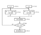
次にCRC演算装置4の動作について説明する。図10はCRC演算装置4の動作の流れを示すフローチャートであり、例として2分割されている場合を示している。この動作は大略次の4つの行程で行われる。
【0060】
第一行程.
受信系列を第一ターボ復号器121と第二ターボ復号器122に夫々入力する(ステップST101、ステップST102)。
【0061】
第二行程.
つぎに第一ターボ復号器121による復号とCRC演算の一部である除算を行い(ステップST103)、第二ターボ復号器122による復号とCRC演算の一部である除算を行う(ステップST104)。復号と除算は同時に行うため、図10のフローチャートでは合わせて記している。また、ステップST103とステップST104は同時に行われる。
【0062】
第一ターボ復号器121と第二ターボ復号器122では、まずインターリーブした状態の復号を行い、次にインターリーブされていない状態の復号を行う。インターリーブされていない状態の復号結果は、受信多項式の高次より降順に出力されるため、その結果を随時、除算回路123、除算回路124へ入力する。復号結果を随時除算回路へ入力することで除算とターボ復号を並列に行うことができ、復号が終了すれば除算も終了することになる。
【0063】
第三行程.
除算回路123、124を構成するシフトレジスタの状態は、各ブロックの生成多項式g(x)による剰余を示しており、その結果、式(4)で表すに示すzi(x)[z0(x)125、z1(x)126]を読み出し、CRC結果算出部127へ入力する。CRC結果算出部127では、第二行程で求めた各除算結果zi(x)に対し、剰余の次数を合わせるために式(5)で示すy(x)128との乗算と加算を行ってCRC結果を算出し(ステップST105)、誤り判定部131で誤りの有無を判断して(ステップST106)、ターボ復号繰り返し演算の制御信号を出す。この間に要する処理時間は乗算と加算、誤りを判定する数クロックのみである。なお、y(x)128は1つの受信多項式ブロックの大きさNが決まれば、求めることができるので、予め計算しておく。
【0064】
本来、シフトレジスタでfi(x)・xi・Nの生成多項式g(x)による剰余を求める場合に、(i+1)N回のクロックを要するが、第二行程の演算ではN回分の演算しか行っていないため、剰余zi(x)は要求している次数まで除算が進んでいない。そこで、xNの生成多項式g(x)による剰余である、式(5)に示すy(x)128を、生成多項式g(x)を法としてGF(2)上で、剰余zi(x)に乗算することで、シフトレジスタによる残りの演算をした結果と同じ結果を得ることができる。シフトレジスタによる演算がi・N回足りなければy(x)128を剰余zi(x)にi回乗算することで、すべての次数を調整することができる。
【0065】
第四行程.
ステップST106で誤りがあればステップST103、ステップST104からターボ復号を繰り返し、一方、誤りがなければ復号結果を出力する(ステップST107)。なお、繰り返しの最大回数を設定しておき、繰り返し演算を所定回数で打ち切るようにしておいてもよい。
【0066】
以上説明したように、この実施の形態4によれば、ターボ復号繰り返し回数をCRC演算結果から制御する場合に、CRC演算並列化と復号順序を入れ替えたターボ復号方法を組み合わせることにより、CRC演算による遅延時間を受信多項式ブロックの次数を調整する乗算と加算および誤り判定のみにし、従来よりも短い遅延時間で繰り返し回数制御を行うことが可能となり、制御を高速にできる効果がある。
【0067】
実施の形態5.
この発明に係る実施の形態5について、図11および図12を参照して説明する。なお、図11は実施の形態5に係るCRC演算装置5の回路構成を示す図であり、図12はこのCRC演算装置5の動作を示すブロック図である。
【0068】
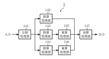
実施の形態5のCRC演算装置5は、高速にCRC検査ビットを得ることを目的としている。図11は実施の形態5のCRC演算装置5の構成を示しており、3分割した場合の例であって、情報系列を式(3)に従って複数ブロックに分割する分割処理部141、CRC生成多項式による除算を行う除算処理部142、143、144、式(7)に従い剰余の次数を調整する乗算を行う乗算処理部145、146、それらの加算を行う加算処理部147を備えている。情報系列を入力して分割し、夫々の情報系列に対し除算を並列に処理して、乗算、加算を行うことでCRC検査ビットを生成するCRC演算装置である。
【0069】
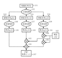
次にCRC演算装置5の動作について説明する。図12はCRC演算装置5を示すブロック図であり、例として3分割した場合を示している。この動作は大略次の5つの行程で行われる。
【0070】
第一行程.
複数の除算回路を備えた装置に情報系列f(x)151を入力し、除算回路の個数と同数に式(3)に応じて分割処理152する。
【0071】
第二行程.
分割された情報系列ブロックf0(x)153、f1(x)154、f2(x)155を、夫々の情報系列ブロックの高次より順に入力する。
【0072】
第三行程.
各情報系列ブロックf0(x)153、f1(x)154、f2(x)155を夫々の高次から順に除算回路に入力することで、各除算処理156、157、158を並列に行う。各情報系列ブロックのデータを全て入力し終えた時点で、各除算処理156〜158の回路を構成するシフトレジスタの状態は、各ブロックの生成多項式g(x)による剰余を示しており、結果は式(4)で示す剰余zi(x)〔z0(x)159、z1(x)160、z2(x)161〕として読み出す。
【0073】
第四行程.
第三行程で求めた剰余zi(x)に対し、次数を合わせるためにy(x)162との乗算処理163、164、165を式(7)に従って行う。y(x)162は情報系列ブロックの1ブロックの大きさNが決まれば求めることができるので、予め計算しておく。
【0074】
本来、シフトレジスタでfi(x)・xi・Nの生成多項式g(x)による剰余を求める場合に、(i+1)N回のクロックを要するが、第三行程の演算ではN回分の演算しか行っていないため、剰余zi(x)は要求している次数まで除算が進んでいない。そこで、xNの生成多項式g(x)による剰余である、式(5)に示すy(x)162を、生成多項式g(x)を法としてGF(2)上で、剰余zi(x)に乗算することで、シフトレジスタによる残りの演算をした結果と同じ結果を得ることができる。シフトレジスタによる演算がi・N回足りなければy(x)162を剰余zi(x)にi回乗算することで、すべての次数を調整することができる。
【0075】
第五行程.
最後に、第四行程で行ったすべての乗算の結果を、式(7)に示すように加算処理166を行えば、CRC検査ビット167であるz(x)を得ることができる。
【0076】
以上説明したように、この実施の形態5によれば、CRC検査ビットを付加する処理を分割して並列化して行うことにより、演算を高速処理できる効果がある。
【0077】
実施の形態6.
この発明に係る実施の形態6について、図13〜図15を参照して説明する。なお、図13は実施の形態6に係るCRC演算装置6の回路構成を示す図であり、図14は図13のCRC検査ビット生成部の構成を示す図であり、図15はこのCRC演算装置6の一部を示す構成図である。
【0078】
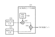
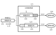
実施の形態6は、情報系列からCRC検査ビットを生成し、CRC検査ビットを付加した情報系列に対して符号分割を行い、分割された夫々の系列に対して別々にターボ符号化する場合を仮定している。実施の形態6のCRC演算装置6は上記の場合に、CRC検査ビット生成および符号化の処理を高速化することを目的としている。図13は実施の形態6の構成図を示しており、情報系列を符号分割の規則に従って分割する分割処理部171と、各分割符号に対し除算を行う除算処理部172、除算処理部173と、除算結果に対し乗算と加算を行ってCRC検査ビットを生成するCRC検査ビット生成部174と、ターボ符号化するターボ符号化部175、ターボ符号化部176を備えている。このCRC演算装置6は情報系列を符号分割の規則に従って分割し、除算を並列して行い、剰余からCRC検査ビットを算出して付加するCRC演算装置である。なお、除算処理部172、173の除算回路はシフトレジスタで構成し、乗算器は排他的論理和回路を用いた生成多項式を法とするGF(2)上の乗算回路を備えている。
【0079】
次にCRC演算装置6の動作について説明する。ここでは、例として2分割されている場合を示している。この動作は大略次の4つの行程で行われる。
【0080】
第一行程.
まず、図13に示すように情報系列を分割処理部171に入力し、符号分割の規則に従って分割処理を行う。本来、CRC検査ビットを付加してから符号分割を行うため、図15に示すようにCRC検査ビット長を含めた大きさで分割する必要がある。このときに、符号分割における調整ビット196は付加しておき、CRC検査ビット193は空けておくことになる。
【0081】
図15に示す分割処理部171は情報長nの情報系列191が入力されると、CRC検査ビット193長を考慮した、除算処理部172の除算回路194に入力される情報系列ブロックf0(x)となる情報系列192と、調整ビット196が付加され、除算処理部173の除算回路197に入力される情報系列ブロックf1(x)となる情報系列195とに分割される。
【0082】
第二行程.
第一行程で分割された各情報系列ブロックf0(x)、f1(x)を夫々除算処理部172、除算処理部173へ入力して、各除算を並列処理し、式(4)に示す剰余zi(x)〔z0(x)、z1(x)〕を求める。この場合、f0(x)の除算はCRC検査ビット分だけ早く終える。
【0083】
第三行程.
第二行程で求めた剰余zi(x)を図14に示すCRC検査ビット生成部174に入力し、CRC検査ビット193を求める。CRC検査ビット生成部174では、まず剰余の次数を合わせるためにy(x)181との乗算処理182を式(7)に従って行う。y(x)181は情報系列ブロックの1ブロックの大きさNが決まれば求めることができるので、予め計算しておく。
【0084】
本来、シフトレジスタでfi(x)・xi・Nの生成多項式g(x)による剰余を求める場合に、(i+1)N回のクロックを要するが、第二行程の演算ではN回分の演算しか行っていないため、剰余zi(x)は要求している次数まで除算が進んでいない。そこで、xNの生成多項式g(x)による剰余である、式(5)に示すy(x)181を、生成多項式g(x)を法としてGF(2)上で、剰余zi(x)に乗算することで、シフトレジスタによる残りの演算をした結果と同じ結果を得ることができる。シフトレジスタによる演算がi・N回足りなければy(x)181を剰余zi(x)にi回乗算することで、すべての次数を調整することができる。
【0085】
第四行程.
最後に第三行程で得た、CRC検査ビット193を付加した情報系列ブロックf0(x)をターボ符号化部175で符号化を行い、調整ビット196を付加した情報系列ブロックf1(x)をターボ符号化部176で符号化を行って出力する。SW177はCRC検査ビット生成部174の結果に基づいて情報系列ブロックf0(x)の符号化を制御する。
【0086】
以上説明したように、この実施の形態6によれば、CRC演算を並列化して行うことで、CRC検査ビット生成処理を高速化することができ、本来CRC演算を並列化するために必要であった情報系列の分割処理を符号分割処理で行うことにより、CRC並列化のための分割処理がなくなり、演算を高速処理できる効果がある。
【0087】
実施の形態7.
この発明に係る実施の形態7について、図16および図17を参照して説明する。なお、図16は実施の形態7に係るCRC演算装置7の回路構成を示す図であり、図17はこのCRC演算装置7の一部を示す構成図である。
【0088】
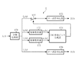
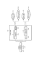
実施の形態7は、情報系列からCRC検査ビットを生成し、CRC検査ビットを付加した情報系列に対して符号分割を行い、分割された夫々の系列に対して別々に畳込み符号化する場合を仮定している。実施の形態7のCRC演算装置7は上記の場合に、CRC検査ビット生成および符号化の処理を高速化することを目的としている。図16は実施の形態7の構成図を示しており、情報系列を符号分割の規則に従って分割する分割処理部201と、各分割符号に対し除算を行う除算処理部202、除算処理部203と、除算結果に対し乗算と加算を行ってCRC検査ビットを生成するCRC検査ビット生成部204と、畳込み符号化する畳込み符号化部205、畳込み符号化部206を備えている。CRC演算装置は情報系列を符号分割の規則に従って分割し、除算を並列して行い、剰余からCRC検査ビットを算出して付加するCRC演算装置である。
【0089】
なお、各除算処理部202、203の除算回路はシフトレジスタで構成し、乗算器は排他的論理和回路を用いた生成多項式を法とするFG(2)上の乗算回路を備えている。
【0090】
次にCRC演算装置7の動作について説明する。ここでは、例として2分割されている場合を示している。この動作は大略次の4つの行程で行われる。
【0091】
第一行程.
まず、図16に示すように情報系列を分割処理部201に入力し、符号分割の規則に従って分割処理を行う。本来、CRC検査ビットを付加してから符号分割を行うため、図17に示すようにCRC検査ビット長を含めた大きさで分割する必要がある。このときに、符号分割における調整ビット196は付加しておき、CRC検査ビット193は空けておくことになる。
【0092】
図17に示す分割処理部201は情報長nの情報系列211が入力されると、CRC検査ビット213長を考慮した、除算処理部202の除算回路214に入力される情報系列ブロックf0(x)となる情報系列212と、調整ビット217が付加され、除算処理部203の除算回路218に入力される情報系列ブロックf1(x)となる情報系列216とに分割される。
【0093】
第二行程.
第一行程で分割された式(3)で示す各情報系列ブロックf0(x)、f1(x)を夫々除算処理部202、除算処理部203へ入力して、各除算を並列処理し、式(4)に示す剰余zi(x)〔z0(x)、z1(x)〕を求める。この場合、f0(x)の除算はCRC検査ビット分だけ早く終える。
【0094】
また、除算回路214、218へ入力したビットは夫々同時に畳込み符号器215、畳込み符号器219へ入力し、除算と並列して畳込み符号化を行う。ただし、f0(x)におけるCRC検査ビット部分の畳込み符号化は、次の第三行程の処理を終えてから、CRC検査ビットを入力して行う。
【0095】
第三行程.
第二行程で求めた剰余zi(x)からCRC検査ビット213を求めるが、これは実施の形態6で図14を参照して説明したことと同様である。
【0096】
本来、シフトレジスタでfi(x)・xi・Nの生成多項式g(x)による剰余を求める場合に、(i+1)N回のクロックを要するが、第二行程の演算ではN回分の演算しか行っていないため、剰余zi(x)は要求している次数まで除算が進んでいない。そこで、xNの生成多項式g(x)による剰余である、式(5)に示すy(x)を、生成多項式g(x)を法としてGF(2)上で、剰余zi(x)に乗算することで、シフトレジスタによる残りの演算をした結果と同じ結果を得ることができる。シフトレジスタによる演算がi・N回足りなければy(x)を剰余zi(x)にi回乗算することで、すべての次数を調整することができる。全情報系列f(x)に対する剰余を得るために、第三行程で行った全ての乗算結果の加算を式(7)に従って行えば、CRC検査ビットであるz(x)を得ることができる。
【0097】
第四行程.
最後にCRC検査ビット213を付加した情報系列ブロックf0(x)を畳込み符号化部205の畳込み符号器215で符号化を行い、調整ビット217を付加した情報系列ブロックf1(x)を畳込み符号化部206の畳込み符号器219で符号化を行って出力する。SW207はCRC検査ビット生成部204の結果に基づいて多項式f0(x)の符号化を制御する。
【0098】
以上説明したように、この実施の形態7によれば、符号分割のある場合のCRC演算と畳込み符号化を並列して行うことで、CRC演算による遅延時間が削減し、CRC演算並列化のための分割処理を符号分割処理で行うことで、CRC演算並列化のための分割処理がなくなり、符号化処理を高速処理できるという効果がある。
【0099】
【発明の効果】
以上のように、この発明によれば、除算処理を分割して並列に行うことにより、低次の受信多項式ブロックは高次ブロックの除算の終了を待つ必要がなく、処理を高速化することが可能であり、また、回路規模を小さくできる効果がある。
【図面の簡単な説明】
【図1】本発明の実施の形態1に係るCRC演算装置の回路構成を示す図である。
【図2】本発明の実施の形態1に係るCRC演算装置の動作を示すブロック図である。
【図3】本発明の実施の形態2に係るCRC演算装置の回路構成を示す図である。
【図4】本発明の実施の形態2に係るCRC演算装置の動作を示すブロック図である。
【図5】本発明の実施の形態3に係るCRC演算装置の回路構成を示す図である。
【図6】本発明の実施の形態3に係るCRC演算装置で用いるターボ復号部の構成を示す図である。
【図7】本発明の実施の形態3に係るCRC演算装置の動作を示すブロック図である。
【図8】本発明の実施の形態4に係るCRC演算装置の構成を示すブロック図である。
【図9】図8のCRC結果算出部の構成を示す図である。
【図10】本発明の実施の形態4に係るCRC演算装置の動作の流れ示すフローチャートである。
【図11】本発明の実施の形態5に係るCRC演算装置の回路構成を示す図である。
【図12】本発明の実施の形態5に係るCRC演算装置の動作を示すブロック図である。
【図13】本発明の実施の形態6に係るCRC演算装置の回路構成を示す図である。
【図14】図13のCRC検査ビット生成部の構成を示す図である。
【図15】本発明の実施の形態6に係るCRC演算装置の一部を示す構成図である。
【図16】本発明の実施の形態7に係るCRC演算装置の回路構成を示す図である。
【図17】本発明の実施の形態7に係るCRC演算装置の一部を示す構成図である。
【符号の説明】
1,2,3,4,5,6,7 CRC演算装置、11,12,13,42,43,44,73,74,142,143,144,172,173,202,203 除算処理部、14,15,45,46,75,145,146 乗算処理部、16,47,76,147 加算処理部、21,53,103 受信多項式f0(x)、22,54,104 受信多項式f1(x)、23,55 受信多項式f2(x)、24,25,26,56,57,58,156,157,158除算処理、27,59,107,125,159 剰余z0(x)、28,60,108,126,160 剰余z1(x)、29,61,161 剰余z2(x)、30,62,109,128,162,181 剰余y(x)、31,32,33,63,64,65,110,129,163,164,165,182 乗算処理、34,66,111,130,166,183 加算処理、35,67,112 CRC演算結果z(x)、41,141,171,201 分割処理部、51 受信多項式f(x)、52,152 分割処理、71,72ターボ復号部、81,82,83 インターリーバ、84,85,86 第二要素復号器、87,88 デインターリーバ、89,90,91 第一要素復号器、92 CRC演算部、101,121 第一ターボ復号器、102,122第二ターボ復号器、105,106,123,124,194,197,214,218 除算回路、127 CRC結果算出部、131 誤り判定部、151 情報系列f(x)、153 情報系列f0(x)、154 情報系列f1(x)、155 情報系列f2(x)、167 CRC検査ビット、174,204 CRC検査ビット生成部、175,176 タ−ボ符号化部、177,207 SW、191,192,195,211,212,216 情報系列、193,213 CRC検査ビット用マージン、196,217 調整ビット、205,206 畳込み符号化部、215,219 畳込み符号器。[0001]
BACKGROUND OF THE INVENTION
The present invention relates to a CRC calculation method and a CRC calculation device related to CRC (Cyclic Redundancy Check) calculation for detecting an error in digital information.
[0002]
[Prior art]
The CRC code is generated by adding a remainder of the information sequence i (x) by the generating polynomial g (x) to the information sequence. To add an n-bit CRC check bit, an n-th generation polynomial g (x) is prepared, a remainder v (x) of g (x) of i (x) is obtained, and v (x) is used as a check bit. Append.
[0003]
When performing error detection, i (x) · x n The remainder z (x) is obtained from the generating polynomial g (x) of the receiving polynomial f (x) corresponding to + v (x). If there is no error in the reception polynomial r (x), r (x) = i (x) · x n + V (x) is divisible by the generator polynomial g (x), and the remainder z (x) is 0. If there is an error, it is not divisible and 0, so it is possible to detect an error (for example, non-patent Reference 1).
[0004]
Since the CRC operation for generating and checking the CRC check bits is division based on a generator polynomial, it can be configured using a shift register. Further, it is possible to speed up the calculation by reading and calculating the data polynomial in a plurality of bits in parallel.
[0005]
A conventional speeding-up method by parallelizing CRC operations is described in
[Expression 1]
[Non-Patent Document 1]
"Code Theory" IEICE (p.118)
[Patent Document 1]
JP-A-8-330976
[0007]
[Problems to be solved by the invention]
In the conventional CRC calculation, since the reception polynomial is input to the division circuit in order from the higher order, the number of steps for the code length is required for processing, and there is a problem that the delay time is large. Further, when division is performed on a plurality of reception polynomial blocks, it is necessary to perform division from a higher order of the reception polynomial, and therefore, a lower order reception polynomial block cannot be started unless the higher order calculation is completed. Therefore, the processing delay for performing the CRC operation on the received signal is required for the division for all the codes.
[0008]
Therefore, a method has been proposed in which CRC operations are parallelized to increase the operation speed, but this is a method of multiplying a received polynomial block in advance and then performing a division process. Since it is difficult to multiply the data due to restrictions such as the above, it is difficult to cope with a case where the size of one block to be divided is limited and the size of one block changes. Conversely, when one block is made small, the number of parallelization increases when the code length is long, and the circuit scale becomes large. Further, when a polynomial for performing CRC calculation is input in parallel bit by bit, it is necessary to hold information up to the data size unit to be read.
[0009]
In addition, when a concatenated code of a turbo code and a CRC code is used and there are a plurality of reception polynomials, it is necessary to rearrange the data polynomial at the end of the turbo decoding operation. If decoding for all data is not completed, the CRC operation is performed. Cannot start. Even if turbo decoding with a reversed decoding order is applied, if there are multiple reception polynomials, division for low-order reception polynomials must wait for the completion of high-order computation, and only the division for all codes is processed. There was a problem of taking time.
[0010]
The present invention has been made to solve the above-described problems. After performing a division operation based on a CRC generator polynomial on data input in parallel to each input data, multiplication and addition of degree adjustment are performed. The purpose of this is to speed up the computation.
[0011]
[Means for Solving the Problems]
In the CRC calculation method according to the present invention, the reception polynomial is divided into a plurality of blocks and input in parallel, and a division operation based on the CRC generation polynomial is performed in parallel on each reception polynomial, and the result of the division operation is received. After performing multiplication for adjusting the order of the polynomial block, each of the multiplication results is added to obtain a CRC result for the reception polynomial.
[0012]
In the CRC calculation method according to the present invention, the reception polynomial is divided into a plurality of reception polynomial blocks, division operations based on the CRC generation polynomial are performed in parallel, and the order of the reception polynomial block is adjusted to the result of the division operation. After multiplication, each of the multiplication results is added to obtain a CRC result for all reception polynomials.
[0013]
In the CRC calculation apparatus according to the present invention, a plurality of division circuits based on a CRC generation polynomial, a multiplier that performs multiplication for adjusting the order of the remainder, and addition are performed in accordance with received data input in parallel And an adder.
[0014]
In the CRC calculation method according to the present invention, an information sequence is divided into a plurality of blocks and input in parallel, and a division operation based on a CRC generator polynomial is performed on each information sequence block in parallel, and the result of the division operation is obtained. After performing multiplication for adjusting the order of the information sequence block, each of the multiplication results is added to generate a CRC check bit.
[0015]
In the CRC calculation method according to the present invention, an information sequence is divided into a plurality of blocks, division operations based on a CRC generator polynomial are performed in parallel, and multiplication and addition are performed to match the degree of each block to the remainder of the division operation. Thus, a CRC check bit is obtained.
[0016]
A CRC calculation apparatus according to the present invention includes a division processing unit that divides an information sequence into a plurality of blocks, a plurality of division units based on a CRC generator polynomial, a multiplication unit that performs multiplication for adjusting a degree of a remainder, and the multiplication Adding means for adding multiplication results by the means.
[0017]
DETAILED DESCRIPTION OF THE INVENTION
An embodiment of the present invention will be described below.
[0018]
The parallelization of CRC calculation by the CRC calculation method of the present invention is based on the following polynomial division method. The value to be obtained by the CRC calculation is a remainder z (x) by the generator polynomial g (x) with respect to the polynomial f (x) and can be expressed by Expression (2).
[Expression 2]
[Equation 3]
Expression (3) can also be regarded as dividing the polynomial f (x) into m, and the size of one divided block is N. Furthermore, the polynomial block f i (X) and power x N When the remainder by the generator polynomial g (x) is expressed by Equation (4) and Equation (5)
[Expression 4]
[Formula 6]
From equation (7), each remainder z of the divided polynomial block i It can be seen that the remainder z (x) of the generator polynomial g (x) of the total polynomial f (x) is obtained by multiplying (x) by y (x) for adjusting the order and adding them.
[0021]
Next, the above will be applied to CRC calculation, and a specific example will be described. The first embodiment is intended to perform division on received data input in parallel in parallel. The
[0022]
The
[0023]
Next, the operation of the
[0024]
First step.
Divided reception polynomial f 0 (X) 21, f 1 (X) 22, f 2 (X) 23 is input to the
[0025]
Second stroke.
Each receiving polynomial f 0 (X) 21, f 1 (X) 22, f 2 (X) 23 is input to the division circuit in order from each higher order, whereby
[0026]
Third process.
Remainder z obtained in the second process i In order to match the degree to (x), multiplication processes 31, 32, and 33 with y (x) 30 are performed according to equation (7). Since y (x) 30 can be obtained if the size N of one block of the reception polynomial is determined, it is calculated in advance.
[0027]
Originally f is a shift register i (X) x i ・ N (I + 1) N clocks are required to obtain the remainder using the generator polynomial g (x), but the remainder z has only N computations, so the remainder z i In (x), the division has not progressed to the requested order. So x N Y (x) 30 shown in the equation (5), which is a remainder of the generator polynomial g (x), is represented on the GF (2) modulo the generator polynomial g (x). i By multiplying (x), it is possible to obtain the same result as the result of the remaining calculation by the shift register. If the operation by the shift register is not i · N times, y (x) 30 is the remainder z i All orders can be adjusted by multiplying (x) i times.
[0028]
Fourth process.
Finally, if all the multiplication results performed in the third step are subjected to
[0029]
As described above, according to the first embodiment, the division process is divided and performed in parallel, so that the low-order reception polynomial block does not need to wait for the completion of the division of the high-order block, and the process is performed at high speed. If the reception polynomial is output in order from the higher order in each decoding, it is possible to perform CRC calculation simultaneously with decoding by inputting each result to the sequential division circuit.
[0030]
In addition, since each reception polynomial block is first divided and then multiplied, multiplication is performed by a polynomial less than the order of the generator polynomial, and the size of each reception polynomial block is large or changes. In addition, there is an effect that the circuit scale can be reduced without requiring a large memory or circuit.
[0031]
A second embodiment according to the present invention will be described with reference to FIGS. 3 is a diagram showing a circuit configuration of the
[0032]
The second embodiment is different from the first embodiment in that the CRC calculation is parallelized by dividing the reception polynomial. FIG. 3 shows the
[0033]
When dividing the reception polynomial, the address read from the memory is controlled according to the division, the division circuit of each division processing unit 42 to 44 is configured by a shift register, and the multiplier uses an exclusive OR circuit. A multiplication circuit on GF (2) modulo the generator polynomial is provided.
[0034]
Next, the operation of the
[0035]
First step.
A receiving polynomial f (x) 51 is input to an apparatus having a plurality of division circuits, and
[0036]
Second stroke.
Divided reception polynomial f 0 (X) 53, f 1 (X) 54, f 2 (X) 55 is input in parallel to the respective divider circuits.
[0037]
Third process.
Each receiving polynomial f 0 (X) 53, f 1 (X) 54, f 2 By inputting (x) 55 to the division circuit in order from each higher order, each
[0038]
Fourth process.
Remainder z obtained in the third process i In order to match the order to (x), multiplication processes 63, 64, and 65 with y (x) 62 are performed according to equation (7). Since y (x) 62 can be obtained if the size N of one block of the reception polynomial is determined, it is calculated in advance.
[0039]
Originally f is a shift register i (X) x i ・ N (I + 1) N clocks are required to obtain the remainder using the generator polynomial g (x), but since the operation in the third step only performs N operations, the remainder z i In (x), the division has not progressed to the requested order. So x N Y (x) 62 shown in the equation (5), which is a remainder of the generator polynomial g (x), is represented on the GF (2) modulo the generator polynomial g (x). i By multiplying (x), it is possible to obtain the same result as the result of the remaining calculation by the shift register. If the operation by the shift register is not i · N times, y (x) 62 is the remainder z i All orders can be adjusted by multiplying (x) i times.
[0040]
5th process.
Finally, if all the multiplication results performed in the fourth step are subjected to
[0041]
As described above, according to the second embodiment, the received reception polynomial is divided and divided, and the CRC calculation related to the divided low-order reception polynomial block is waited for the completion of the high-order calculation. Since it is not necessary, there is an effect that processing can be performed at high speed.
[0042]
Embodiment 3 FIG.
Embodiment 3 according to the present invention will be described with reference to FIGS. 5 is a diagram illustrating a circuit configuration of the CRC calculation device 3 according to the third embodiment, FIG. 6 is a diagram illustrating a configuration of a turbo decoding unit used in the CRC calculation device 3, and FIG. FIG. 6 is a diagram illustrating an operation of the arithmetic device 3.
[0043]
The CRC calculation device 3 according to the third embodiment aims at speeding up calculation when turbo decoding is performed in parallel on a plurality of received sequences and a residual error is detected by CRC thereafter. FIG. 5 is a configuration diagram of the CRC calculation device 3 and shows an example in which two are parallelized.
[0044]
The division circuit constituting the
[0045]
In addition, if a turbo decoding method in which the decoding calculation order is changed is used for turbo decoding, calculation processing can be performed at higher speed. The turbo decoding whose order has been changed is the operation of the first element decoder for calculating the likelihood of the non-interleaved received sequence, first the operation of the second element decoder for calculating the likelihood of the interleaved received sequence. A turbo decoding method which is performed later, and performs path metric calculation for the number of information bits n in each element decoder, first performing backward path metric calculation from time point n to 1, and later performing forward path metric calculation from
[0046]
In this turbo decoding method, as shown in FIG. 6, first, input data is interleaved by an
[0047]
In FIG. 6, the symbol “%” of the
[0048]
Next, the operation of the CRC calculation device 3 will be described. FIG. 7 is a block diagram showing the operation of the CRC calculation device 3, and shows a case where it is divided into two as an example. This operation is generally performed in the following four steps.
[0049]
First step.
The received sequence is input to the
[0050]
Second stroke.
Reception polynomial f that is output bit by bit from the higher order in the first step 0 (X) 103, f 1 (X) 104 is input to the
[0051]
Third process.
Remainder z obtained in the second process i In order to match the degree to (x),
[0052]
Originally f is a shift register i (X) x i ・ N (I + 1) N clocks are required to obtain the remainder using the generator polynomial g (x), but the remainder z has only N computations, so the remainder z i In (x), the division has not progressed to the requested order. So x N Y (x) 109 shown in the equation (5), which is a remainder by the generator polynomial g (x) of, modulo the generator polynomial g (x) on GF (2), and the remainder z i By multiplying (x), it is possible to obtain the same result as the result of the remaining calculation by the shift register. If the operation by the shift register is not i · N times, y (x) 109 is the remainder z i All orders can be adjusted by multiplying (x) i times.
[0053]
Fourth process.
Finally, if all the results of multiplication performed in the third step are subjected to
[0054]
As described above, according to the third embodiment, by combining a parallel CRC calculation and a turbo decoding method in which the decoding order is switched, a multi-input reception polynomial is interleaved in the final round of turbo decoding. When there is no decoding, the CRC calculation can be performed at the same time, the delay time by the CRC calculation can be greatly reduced, and after the turbo decoding is finished, the CRC result can be obtained only by the delay time by the multiplication and addition of the order adjustment, There is an effect that processing can be performed at high speed.
[0055]
Embodiment 4 FIG.
Embodiment 4 according to the present invention will be described with reference to FIGS. 8 is a block diagram showing the configuration of the CRC calculation device 4 according to Embodiment 4, FIG. 9 is a diagram showing the configuration of the CRC result calculation unit shown in FIG. 8, and FIG. 10 is this CRC calculation device. 4 is a flowchart showing a flow of operation of FIG.
[0056]
As shown in FIGS. 8 and 9, the CRC calculation device 4 according to the fourth embodiment is a case in which CRC calculation is performed while turbo decoding is performed in parallel on a plurality of received sequences to control the number of turbo decoding iterations. The CRC calculation device 4 is shown as an example in which the CRC calculation device 4 is parallelized, and includes a
[0057]
If turbo decoding with a reversed order is applied to turbo decoding, the processing can be further speeded up. The turbo decoding whose order has been changed is that the operation of the
[0058]
The CRC
[0059]
Next, the operation of the CRC calculation device 4 will be described. FIG. 10 is a flowchart showing the flow of the operation of the CRC arithmetic unit 4, and shows a case where it is divided into two as an example. This operation is generally performed in the following four steps.
[0060]
First step.
The received sequence is input to
[0061]
Second stroke.
Next, decoding by the
[0062]
The
[0063]
Third process.
The state of the shift register that constitutes the
[0064]
Originally f is a shift register i (X) x i ・ N (I + 1) N clocks are required to obtain the remainder using the generator polynomial g (x), but the remainder z has only N computations, so the remainder z i In (x), the division has not progressed to the requested order. So x N Y (x) 128 shown in the equation (5), which is a remainder of the generator polynomial g (x), is represented on the GF (2) modulo the generator polynomial g (x). i By multiplying (x), it is possible to obtain the same result as the result of the remaining calculation by the shift register. If the operation by the shift register is not i · N times, y (x) 128 is the remainder z i All orders can be adjusted by multiplying (x) i times.
[0065]
Fourth process.
If there is an error in step ST106, the turbo decoding is repeated from step ST103 and step ST104. On the other hand, if there is no error, the decoding result is output (step ST107). Note that the maximum number of repetitions may be set, and the repetition calculation may be terminated at a predetermined number of times.
[0066]
As described above, according to the fourth embodiment, when the number of iterations of turbo decoding is controlled from the CRC calculation result, the CRC calculation is performed by combining the CRC calculation parallelization and the turbo decoding method in which the decoding order is switched. The delay time is limited only to multiplication, addition and error determination for adjusting the order of the reception polynomial block, and it is possible to perform the number of repetitions control with a delay time shorter than the conventional one, and there is an effect that the control can be performed at high speed.
[0067]
Embodiment 5 FIG.
Embodiment 5 according to the present invention will be described with reference to FIGS. FIG. 11 is a diagram showing a circuit configuration of the CRC calculation device 5 according to the fifth embodiment, and FIG. 12 is a block diagram showing an operation of the CRC calculation device 5.
[0068]
The CRC computing device 5 according to the fifth embodiment is intended to obtain CRC check bits at high speed. FIG. 11 shows the configuration of the CRC calculation device 5 according to the fifth embodiment, which is an example in the case of division into three, a
[0069]
Next, the operation of the CRC calculation device 5 will be described. FIG. 12 is a block diagram showing the CRC calculation device 5, and shows a case where it is divided into three as an example. This operation is generally performed in the following five steps.
[0070]
First step.
The information series f (x) 151 is input to a device having a plurality of division circuits, and the division processing 152 is performed according to the equation (3) to the same number as the number of division circuits.
[0071]
Second stroke.
Divided information sequence block f 0 (X) 153, f 1 (X) 154, f 2 (X) 155 is input in order from the higher order of each information sequence block.
[0072]
Third process.
Each information series block f 0 (X) 153, f 1 (X) 154, f 2 (X) Each
[0073]
Fourth process.
Remainder z obtained in the third process i In order to match the order to (x),
[0074]
Originally f is a shift register i (X) x i ・ N (I + 1) N clocks are required to obtain the remainder using the generator polynomial g (x), but since the operation in the third step only performs N operations, the remainder z i In (x), the division has not progressed to the requested order. So x N Y (x) 162 shown in the equation (5), which is a remainder of the generator polynomial g (x), is represented on the GF (2) modulo the generator polynomial g (x). i By multiplying (x), it is possible to obtain the same result as the result of the remaining calculation by the shift register. If the operation by the shift register is not i · N times, y (x) 162 is the remainder z i All orders can be adjusted by multiplying (x) i times.
[0075]
5th process.
Finally, if all the multiplication results performed in the fourth step are subjected to
[0076]
As described above, according to the fifth embodiment, the processing for adding the CRC check bit is divided and performed in parallel, so that the operation can be processed at high speed.
[0077]
Embodiment 6 FIG.
Embodiment 6 according to the present invention will be described with reference to FIGS. 13 is a diagram illustrating a circuit configuration of the CRC calculation device 6 according to the sixth embodiment, FIG. 14 is a diagram illustrating a configuration of the CRC check bit generation unit in FIG. 13, and FIG. 15 is a diagram illustrating the CRC calculation device. 6 is a configuration diagram showing a part of FIG.
[0078]
In the sixth embodiment, it is assumed that CRC check bits are generated from an information sequence, code division is performed on the information sequence to which the CRC check bit is added, and each divided sequence is separately turbo-encoded. is doing. The CRC computing device 6 of the sixth embodiment aims to speed up the CRC check bit generation and encoding processing in the above case. FIG. 13 shows a configuration diagram of the sixth embodiment. A
[0079]
Next, the operation of the CRC calculation device 6 will be described. Here, the case where it is divided into two is shown as an example. This operation is generally performed in the following four steps.
[0080]
First step.
First, as shown in FIG. 13, an information series is input to the
[0081]
When the
[0082]
Second stroke.
Each information sequence block f divided in the first step 0 (X), f 1 (X) is input to the
[0083]
Third process.
Remainder z obtained in the second process i (X) is input to the CRC check
[0084]
Originally f is a shift register i (X) x i ・ N (I + 1) N clocks are required to obtain the remainder using the generator polynomial g (x), but the remainder z has only N computations, so the remainder z i In (x), the division has not progressed to the requested order. So x N Y (x) 181 shown in the equation (5), which is a remainder by the generator polynomial g (x) of, and a remainder z on GF (2) modulo the generator polynomial g (x) i By multiplying (x), it is possible to obtain the same result as the result of the remaining calculation by the shift register. If the operation by the shift register is not i · N times, y (x) 181 is the remainder z i All orders can be adjusted by multiplying (x) i times.
[0085]
Fourth process.
Finally, information sequence block f with
[0086]
As described above, according to the sixth embodiment, the CRC check bit generation process can be speeded up by performing the CRC calculation in parallel, which is originally necessary for parallelizing the CRC calculation. By performing the information sequence division processing by code division processing, there is no division processing for CRC parallelization, and there is an effect that computation can be performed at high speed.
[0087]
Embodiment 7 FIG.
A seventh embodiment according to the present invention will be described with reference to FIGS. 16 is a diagram showing a circuit configuration of the CRC calculation device 7 according to the seventh embodiment, and FIG. 17 is a configuration diagram showing a part of the CRC calculation device 7.
[0088]
In the seventh embodiment, a CRC check bit is generated from an information sequence, code division is performed on the information sequence to which the CRC check bit is added, and convolutional coding is separately performed on each divided sequence. Assumes. The CRC computing device 7 of the seventh embodiment aims to speed up the CRC check bit generation and encoding processing in the above case. FIG. 16 shows a configuration diagram of Embodiment 7, in which a
[0089]
Note that the division circuit of each
[0090]
Next, the operation of the CRC calculation device 7 will be described. Here, the case where it is divided into two is shown as an example. This operation is generally performed in the following four steps.
[0091]
First step.
First, as shown in FIG. 16, an information series is input to the
[0092]
When the
[0093]
Second stroke.
Each information series block f shown by Formula (3) divided | segmented at the 1st process 0 (X), f 1 (X) is input to the
[0094]
The bits input to the division circuits 214 and 218 are simultaneously input to the convolutional encoder 215 and the convolutional encoder 219, respectively, and are subjected to convolutional encoding in parallel with the division. Where f 0 The convolutional encoding of the CRC check bit part in (x) is performed by inputting the CRC check bit after finishing the processing of the next third step.
[0095]
Third process.
Remainder z obtained in the second process i The
[0096]
Originally f is a shift register i (X) x i ・ N (I + 1) N clocks are required to obtain the remainder using the generator polynomial g (x), but the remainder z has only N computations, so the remainder z i In (x), the division has not progressed to the requested order. So x N Y (x) shown in Expression (5), which is a remainder from the generator polynomial g (x), is represented on GF (2) modulo the generator polynomial g (x), and the remainder z i By multiplying (x), it is possible to obtain the same result as the result of the remaining calculation by the shift register. If the operation by the shift register is not i · N times, y (x) is the remainder z i All orders can be adjusted by multiplying (x) i times. In order to obtain the remainder for all information series f (x), if all the multiplication results performed in the third step are added according to equation (7), z (x) which is a CRC check bit can be obtained.
[0097]
Fourth process.
Information sequence block f with
[0098]
As described above, according to the seventh embodiment, by performing CRC calculation and convolutional coding in the case of code division in parallel, the delay time by CRC calculation is reduced, and CRC calculation parallelization is performed. By performing the division processing for the code division processing, there is no division processing for CRC calculation parallelization, and the coding processing can be performed at high speed.
[0099]
【The invention's effect】
As described above, according to the present invention, the division process is divided and performed in parallel, so that the low-order reception polynomial block does not need to wait for the completion of the division of the high-order block, and the processing can be speeded up. This is possible and has the effect of reducing the circuit scale.
[Brief description of the drawings]
FIG. 1 is a diagram showing a circuit configuration of a CRC calculation apparatus according to a first embodiment of the present invention.
FIG. 2 is a block diagram showing an operation of the CRC calculation apparatus according to the first embodiment of the present invention.
FIG. 3 is a diagram showing a circuit configuration of a CRC calculation apparatus according to a second embodiment of the present invention.
FIG. 4 is a block diagram showing an operation of a CRC calculation apparatus according to
FIG. 5 is a diagram showing a circuit configuration of a CRC calculation apparatus according to a third embodiment of the present invention.
FIG. 6 is a diagram showing a configuration of a turbo decoding unit used in a CRC calculation apparatus according to Embodiment 3 of the present invention.
FIG. 7 is a block diagram showing an operation of a CRC calculation apparatus according to Embodiment 3 of the present invention.
FIG. 8 is a block diagram showing a configuration of a CRC calculation apparatus according to Embodiment 4 of the present invention.
FIG. 9 is a diagram illustrating a configuration of a CRC result calculation unit in FIG. 8;
FIG. 10 is a flowchart showing a flow of operation of the CRC calculation apparatus according to the fourth embodiment of the present invention.
FIG. 11 is a diagram showing a circuit configuration of a CRC calculation apparatus according to a fifth embodiment of the present invention.
FIG. 12 is a block diagram showing an operation of the CRC calculation apparatus according to the fifth embodiment of the present invention.
FIG. 13 is a diagram showing a circuit configuration of a CRC calculation apparatus according to a sixth embodiment of the present invention.
14 is a diagram illustrating a configuration of a CRC check bit generation unit in FIG. 13;
FIG. 15 is a configuration diagram showing a part of a CRC calculation apparatus according to a sixth embodiment of the present invention.
FIG. 16 is a diagram showing a circuit configuration of a CRC calculation apparatus according to a seventh embodiment of the present invention.
FIG. 17 is a configuration diagram showing a part of a CRC calculation apparatus according to a seventh embodiment of the present invention.
[Explanation of symbols]
1, 2, 3, 4, 5, 6, 7 CRC arithmetic unit, 11, 12, 13, 42, 43, 44, 73, 74, 142, 143, 144, 172, 173, 202, 203 Division processing unit, 14, 15, 45, 46, 75, 145, 146 Multiplication processing unit, 16, 47, 76, 147 Addition processing unit, 21, 53, 103 Reception polynomial f 0 (X), 22, 54, 104 Reception polynomial f 1 (X), 23,55 Reception polynomial f 2 (X), 24, 25, 26, 56, 57, 58, 156, 157, 158 division processing, 27, 59, 107, 125, 159 remainder z 0 (X), 28, 60, 108, 126, 160 Remainder z 1 (X), 29, 61, 161 Remainder z 2 (X), 30, 62, 109, 128, 162, 181 Remainder y (x), 31, 32, 33, 63, 64, 65, 110, 129, 163, 164, 165, 182 Multiplication processing, 34, 66 , 111, 130, 166, 183 addition processing, 35, 67, 112 CRC calculation result z (x), 41, 141, 171, 201 division processing unit, 51 reception polynomial f (x), 52, 152 division processing, 71 , 72 turbo decoding unit, 81, 82, 83 interleaver, 84, 85, 86 second element decoder, 87, 88 deinterleaver, 89, 90, 91 first element decoder, 92 CRC calculation unit, 101, 121 1st turbo decoder, 102, 122 2nd turbo decoder, 105, 106, 123, 124, 194, 197, 214, 218 Division circuit, 127 CRC result calculation Department, 131 error determination section, 151 information sequence f (x), 153 information sequence f 0 (X), 154 information series f 1 (X) 155 information series f 2 (X), 167 CRC check bit, 174, 204 CRC check bit generation unit, 175, 176 Turbo coding unit, 177, 207 SW, 191, 192, 195, 211, 212, 216 Information series, 193, 213 CRC check bit margin, 196, 217 adjustment bit, 205, 206 convolutional coding unit, 215, 219 convolutional encoder.
Claims (9)
Priority Applications (1)
| Application Number | Priority Date | Filing Date | Title |
|---|---|---|---|
| JP2003169574A JP2005006188A (en) | 2003-06-13 | 2003-06-13 | Crc computation method and crc computing unit |
Applications Claiming Priority (1)
| Application Number | Priority Date | Filing Date | Title |
|---|---|---|---|
| JP2003169574A JP2005006188A (en) | 2003-06-13 | 2003-06-13 | Crc computation method and crc computing unit |
Publications (1)
| Publication Number | Publication Date |
|---|---|
| JP2005006188A true JP2005006188A (en) | 2005-01-06 |
Family
ID=34094674
Family Applications (1)
| Application Number | Title | Priority Date | Filing Date |
|---|---|---|---|
| JP2003169574A Abandoned JP2005006188A (en) | 2003-06-13 | 2003-06-13 | Crc computation method and crc computing unit |
Country Status (1)
| Country | Link |
|---|---|
| JP (1) | JP2005006188A (en) |
Cited By (8)
| Publication number | Priority date | Publication date | Assignee | Title |
|---|---|---|---|---|
| JP2008160663A (en) * | 2006-12-26 | 2008-07-10 | Fujitsu Ltd | Division method for information bit string and its device |
| WO2009019763A1 (en) * | 2007-08-07 | 2009-02-12 | Fujitsu Limited | Error detection device, and error correction/error detection decoding device and method |
| JP2010068429A (en) * | 2008-09-12 | 2010-03-25 | Nec Corp | Cyclic code calculation processing circuit |
| US7890835B2 (en) | 2005-09-12 | 2011-02-15 | Samsung Electronics Co., Ltd. | Cyclic redundancy check circuit and communication system having the same for multi-channel communication |
| US8321777B2 (en) | 2006-12-28 | 2012-11-27 | Samsung Electronics Co., Ltd. | Cyclic redundancy check code generating circuit, semiconductor memory device, and method of driving semiconductor memory device |
| US8700971B2 (en) | 2006-08-22 | 2014-04-15 | Panasonic Corporation | Parallel residue arithmetic operation unit and parallel residue arithmetic operating method |
| US9524206B2 (en) | 2014-08-28 | 2016-12-20 | Fujitsu Limited | Decoding device and error detection method |
| CN117097440A (en) * | 2023-10-18 | 2023-11-21 | 苏州联讯仪器股份有限公司 | CRC (cyclic redundancy check) method for Ethernet packet |
-
2003
- 2003-06-13 JP JP2003169574A patent/JP2005006188A/en not_active Abandoned
Cited By (11)
| Publication number | Priority date | Publication date | Assignee | Title |
|---|---|---|---|---|
| US7890835B2 (en) | 2005-09-12 | 2011-02-15 | Samsung Electronics Co., Ltd. | Cyclic redundancy check circuit and communication system having the same for multi-channel communication |
| US8700971B2 (en) | 2006-08-22 | 2014-04-15 | Panasonic Corporation | Parallel residue arithmetic operation unit and parallel residue arithmetic operating method |
| JP2008160663A (en) * | 2006-12-26 | 2008-07-10 | Fujitsu Ltd | Division method for information bit string and its device |
| US8321777B2 (en) | 2006-12-28 | 2012-11-27 | Samsung Electronics Co., Ltd. | Cyclic redundancy check code generating circuit, semiconductor memory device, and method of driving semiconductor memory device |
| US8966338B2 (en) | 2006-12-28 | 2015-02-24 | Samsung Electronics Co., Ltd. | Cyclic redundancy check code generating circuit, semiconductor memory device, and method of driving semiconductor memory device |
| WO2009019763A1 (en) * | 2007-08-07 | 2009-02-12 | Fujitsu Limited | Error detection device, and error correction/error detection decoding device and method |
| JP2010068429A (en) * | 2008-09-12 | 2010-03-25 | Nec Corp | Cyclic code calculation processing circuit |
| US8402353B2 (en) | 2008-09-12 | 2013-03-19 | Nec Corporation | Cyclic code processing circuit, network interface card, and cyclic code processing method |
| US9524206B2 (en) | 2014-08-28 | 2016-12-20 | Fujitsu Limited | Decoding device and error detection method |
| CN117097440A (en) * | 2023-10-18 | 2023-11-21 | 苏州联讯仪器股份有限公司 | CRC (cyclic redundancy check) method for Ethernet packet |
| CN117097440B (en) * | 2023-10-18 | 2024-03-15 | 苏州联讯仪器股份有限公司 | CRC (cyclic redundancy check) method for Ethernet packet |
Similar Documents
| Publication | Publication Date | Title |
|---|---|---|
| JP4643957B2 (en) | Method for calculating the CRC of a message | |
| KR101211433B1 (en) | Appratus and method of high speed quasi-cyclic low density parity check code having low complexity | |
| US20020007474A1 (en) | Turbo-code decoding unit and turbo-code encoding/decoding unit | |
| JP2005218098A (en) | Reed-solomon decoder circuit of a forward directional chain search system | |
| JP5126230B2 (en) | Error detection method | |
| WO2007034870A1 (en) | Decoding device, and receiving device | |
| JP4976397B2 (en) | Parallel residue computing unit and parallel residue computing method | |
| US8261176B2 (en) | Polynomial division | |
| US20050149832A1 (en) | Methods and apparatus for coding and decoding data using reed-solomon codes | |
| US20170250710A1 (en) | Method and device for calculating a crc code in parallel | |
| JP2005006188A (en) | Crc computation method and crc computing unit | |
| CN1636324A (en) | Chien search cell for an error-correcting decoder | |
| US9065482B1 (en) | Circuit for forward error correction encoding of data blocks | |
| CN108809323B (en) | Method and device for generating cyclic redundancy check code | |
| JP2001127645A (en) | Error correction method and error correction device | |
| US6662336B1 (en) | Error correction method and apparatus | |
| CN110022158B (en) | Decoding method and device | |
| CN108347250B (en) | Fast coding method and apparatus suitable for small amount of redundant Reed-Solomon codes | |
| JP5248300B2 (en) | Error correction decoding apparatus and error correction decoding method | |
| US9287898B2 (en) | Method and circuit for shortening latency of Chien'S search algorithm for BCH codewords | |
| Zhang et al. | Low-power high-efficiency architecture for low-complexity chase soft-decision Reed–Solomon decoding | |
| TWI523437B (en) | Encoding and syndrome computing co-design circuit for bch code and method for deciding the same | |
| CN110504975B (en) | CRC parallel coding and decoding method and coder-decoder based on same | |
| US6704901B1 (en) | Runtime programmable Reed-Solomon decoder | |
| JPH1032497A (en) | Error evaluation polynomial coefficient computing device |
Legal Events
| Date | Code | Title | Description |
|---|---|---|---|
| A621 | Written request for application examination |
Free format text: JAPANESE INTERMEDIATE CODE: A621 Effective date: 20060124 |
|
| A521 | Written amendment |
Free format text: JAPANESE INTERMEDIATE CODE: A821 Effective date: 20071019 |
|
| RD02 | Notification of acceptance of power of attorney |
Free format text: JAPANESE INTERMEDIATE CODE: A7422 Effective date: 20071019 |
|
| RD04 | Notification of resignation of power of attorney |
Free format text: JAPANESE INTERMEDIATE CODE: A7424 Effective date: 20071019 |
|
| A977 | Report on retrieval |
Free format text: JAPANESE INTERMEDIATE CODE: A971007 Effective date: 20080502 |
|
| A131 | Notification of reasons for refusal |
Free format text: JAPANESE INTERMEDIATE CODE: A131 Effective date: 20080513 |
|
| A762 | Written abandonment of application |
Free format text: JAPANESE INTERMEDIATE CODE: A762 Effective date: 20080612 |