JP2005004944A - Optical recording medium and recording/reproducing method and device thereof - Google Patents
Optical recording medium and recording/reproducing method and device thereof Download PDFInfo
- Publication number
- JP2005004944A JP2005004944A JP2004028603A JP2004028603A JP2005004944A JP 2005004944 A JP2005004944 A JP 2005004944A JP 2004028603 A JP2004028603 A JP 2004028603A JP 2004028603 A JP2004028603 A JP 2004028603A JP 2005004944 A JP2005004944 A JP 2005004944A
- Authority
- JP
- Japan
- Prior art keywords
- layer
- recording
- information
- information layer
- recording medium
- Prior art date
- Legal status (The legal status is an assumption and is not a legal conclusion. Google has not performed a legal analysis and makes no representation as to the accuracy of the status listed.)
- Pending
Links
- 230000003287 optical effect Effects 0.000 title claims abstract description 170
- 238000000034 method Methods 0.000 title claims description 51
- 239000000758 substrate Substances 0.000 claims abstract description 115
- 239000010410 layer Substances 0.000 claims description 546
- 230000008859 change Effects 0.000 claims description 53
- 239000000463 material Substances 0.000 claims description 46
- 239000002355 dual-layer Substances 0.000 claims description 22
- 229910052782 aluminium Inorganic materials 0.000 claims description 12
- 229910052718 tin Inorganic materials 0.000 claims description 10
- 229910045601 alloy Inorganic materials 0.000 claims description 9
- 239000000956 alloy Substances 0.000 claims description 9
- 230000008033 biological extinction Effects 0.000 claims description 7
- 229910052804 chromium Inorganic materials 0.000 claims description 7
- 229910052745 lead Inorganic materials 0.000 claims description 7
- 229910052709 silver Inorganic materials 0.000 claims description 7
- 229910052732 germanium Inorganic materials 0.000 claims description 6
- 229910052710 silicon Inorganic materials 0.000 claims description 6
- 229910052717 sulfur Inorganic materials 0.000 claims description 6
- 229910052715 tantalum Inorganic materials 0.000 claims description 6
- 229910052720 vanadium Inorganic materials 0.000 claims description 6
- 229910052738 indium Inorganic materials 0.000 claims description 5
- 229910052757 nitrogen Inorganic materials 0.000 claims description 5
- 229910052733 gallium Inorganic materials 0.000 claims description 4
- 229910052758 niobium Inorganic materials 0.000 claims description 4
- 229910052760 oxygen Inorganic materials 0.000 claims description 4
- 239000002356 single layer Substances 0.000 claims description 4
- 229910052726 zirconium Inorganic materials 0.000 claims description 4
- 229910052697 platinum Inorganic materials 0.000 claims description 3
- 229910052797 bismuth Inorganic materials 0.000 claims description 2
- 238000004040 coloring Methods 0.000 abstract 1
- 239000010408 film Substances 0.000 description 62
- 239000011241 protective layer Substances 0.000 description 60
- 239000012071 phase Substances 0.000 description 50
- 239000000975 dye Substances 0.000 description 47
- 238000009792 diffusion process Methods 0.000 description 31
- 238000002834 transmittance Methods 0.000 description 30
- 229920005989 resin Polymers 0.000 description 25
- 239000011347 resin Substances 0.000 description 25
- 229910052751 metal Inorganic materials 0.000 description 23
- 239000002184 metal Substances 0.000 description 23
- 238000004544 sputter deposition Methods 0.000 description 22
- 230000000694 effects Effects 0.000 description 19
- 230000008569 process Effects 0.000 description 19
- 229910004298 SiO 2 Inorganic materials 0.000 description 17
- -1 phthalocyanine compound Chemical class 0.000 description 17
- 230000035945 sensitivity Effects 0.000 description 17
- 238000002310 reflectometry Methods 0.000 description 14
- XLOMVQKBTHCTTD-UHFFFAOYSA-N Zinc monoxide Chemical compound [Zn]=O XLOMVQKBTHCTTD-UHFFFAOYSA-N 0.000 description 13
- 239000013522 chelant Substances 0.000 description 13
- 238000001953 recrystallisation Methods 0.000 description 13
- 238000002844 melting Methods 0.000 description 11
- 230000008018 melting Effects 0.000 description 11
- 239000000203 mixture Substances 0.000 description 11
- 230000015572 biosynthetic process Effects 0.000 description 10
- 230000000052 comparative effect Effects 0.000 description 10
- 239000013078 crystal Substances 0.000 description 10
- 238000009826 distribution Methods 0.000 description 10
- 230000017525 heat dissipation Effects 0.000 description 10
- 150000001875 compounds Chemical class 0.000 description 9
- 230000007423 decrease Effects 0.000 description 9
- 239000007789 gas Substances 0.000 description 9
- 238000001816 cooling Methods 0.000 description 8
- 150000004767 nitrides Chemical class 0.000 description 8
- 238000010521 absorption reaction Methods 0.000 description 7
- 230000004888 barrier function Effects 0.000 description 7
- 238000005229 chemical vapour deposition Methods 0.000 description 7
- 238000002425 crystallisation Methods 0.000 description 7
- 230000008025 crystallization Effects 0.000 description 7
- 238000004519 manufacturing process Methods 0.000 description 7
- 238000003860 storage Methods 0.000 description 7
- 238000007740 vapor deposition Methods 0.000 description 7
- 239000011701 zinc Substances 0.000 description 7
- 239000011787 zinc oxide Substances 0.000 description 7
- 229910006404 SnO 2 Inorganic materials 0.000 description 6
- 150000002739 metals Chemical class 0.000 description 6
- 125000000217 alkyl group Chemical group 0.000 description 5
- 238000011156 evaluation Methods 0.000 description 5
- 229910052737 gold Inorganic materials 0.000 description 5
- 238000007733 ion plating Methods 0.000 description 5
- 238000005268 plasma chemical vapour deposition Methods 0.000 description 5
- 229920005668 polycarbonate resin Polymers 0.000 description 5
- 239000004431 polycarbonate resin Substances 0.000 description 5
- 229910052725 zinc Inorganic materials 0.000 description 5
- 229910018072 Al 2 O 3 Inorganic materials 0.000 description 4
- 239000000654 additive Substances 0.000 description 4
- 230000000996 additive effect Effects 0.000 description 4
- 125000003545 alkoxy group Chemical group 0.000 description 4
- 125000003118 aryl group Chemical group 0.000 description 4
- 239000012298 atmosphere Substances 0.000 description 4
- 238000000576 coating method Methods 0.000 description 4
- 229910052802 copper Inorganic materials 0.000 description 4
- 238000000354 decomposition reaction Methods 0.000 description 4
- 238000000313 electron-beam-induced deposition Methods 0.000 description 4
- RKJUIXBNRJVNHR-UHFFFAOYSA-N indolenine group Chemical group N1=CCC2=CC=CC=C12 RKJUIXBNRJVNHR-UHFFFAOYSA-N 0.000 description 4
- 229910010272 inorganic material Inorganic materials 0.000 description 4
- 230000001678 irradiating effect Effects 0.000 description 4
- 150000001247 metal acetylides Chemical class 0.000 description 4
- 229910052759 nickel Inorganic materials 0.000 description 4
- PXHVJJICTQNCMI-UHFFFAOYSA-N nickel Substances [Ni] PXHVJJICTQNCMI-UHFFFAOYSA-N 0.000 description 4
- 238000010791 quenching Methods 0.000 description 4
- BOLDJAUMGUJJKM-LSDHHAIUSA-N renifolin D Natural products CC(=C)[C@@H]1Cc2c(O)c(O)ccc2[C@H]1CC(=O)c3ccc(O)cc3O BOLDJAUMGUJJKM-LSDHHAIUSA-N 0.000 description 4
- 239000007790 solid phase Substances 0.000 description 4
- 239000000126 substance Substances 0.000 description 4
- 125000001424 substituent group Chemical group 0.000 description 4
- ANRHNWWPFJCPAZ-UHFFFAOYSA-M thionine Chemical compound [Cl-].C1=CC(N)=CC2=[S+]C3=CC(N)=CC=C3N=C21 ANRHNWWPFJCPAZ-UHFFFAOYSA-M 0.000 description 4
- 238000001771 vacuum deposition Methods 0.000 description 4
- ZWEHNKRNPOVVGH-UHFFFAOYSA-N 2-Butanone Chemical compound CCC(C)=O ZWEHNKRNPOVVGH-UHFFFAOYSA-N 0.000 description 3
- 125000003903 2-propenyl group Chemical group [H]C([*])([H])C([H])=C([H])[H] 0.000 description 3
- CSCPPACGZOOCGX-UHFFFAOYSA-N Acetone Chemical compound CC(C)=O CSCPPACGZOOCGX-UHFFFAOYSA-N 0.000 description 3
- UHOVQNZJYSORNB-UHFFFAOYSA-N Benzene Chemical compound C1=CC=CC=C1 UHOVQNZJYSORNB-UHFFFAOYSA-N 0.000 description 3
- YMWUJEATGCHHMB-UHFFFAOYSA-N Dichloromethane Chemical compound ClCCl YMWUJEATGCHHMB-UHFFFAOYSA-N 0.000 description 3
- RTZKZFJDLAIYFH-UHFFFAOYSA-N Diethyl ether Chemical compound CCOCC RTZKZFJDLAIYFH-UHFFFAOYSA-N 0.000 description 3
- LFQSCWFLJHTTHZ-UHFFFAOYSA-N Ethanol Chemical compound CCO LFQSCWFLJHTTHZ-UHFFFAOYSA-N 0.000 description 3
- XEKOWRVHYACXOJ-UHFFFAOYSA-N Ethyl acetate Chemical compound CCOC(C)=O XEKOWRVHYACXOJ-UHFFFAOYSA-N 0.000 description 3
- OKKJLVBELUTLKV-UHFFFAOYSA-N Methanol Chemical compound OC OKKJLVBELUTLKV-UHFFFAOYSA-N 0.000 description 3
- ZMXDDKWLCZADIW-UHFFFAOYSA-N N,N-Dimethylformamide Chemical compound CN(C)C=O ZMXDDKWLCZADIW-UHFFFAOYSA-N 0.000 description 3
- 229910004541 SiN Inorganic materials 0.000 description 3
- 239000012790 adhesive layer Substances 0.000 description 3
- 238000000137 annealing Methods 0.000 description 3
- 229910002056 binary alloy Inorganic materials 0.000 description 3
- 229910052791 calcium Inorganic materials 0.000 description 3
- 229910052799 carbon Inorganic materials 0.000 description 3
- 238000010586 diagram Methods 0.000 description 3
- 229920001971 elastomer Polymers 0.000 description 3
- 150000002148 esters Chemical class 0.000 description 3
- 150000002222 fluorine compounds Chemical class 0.000 description 3
- 125000005843 halogen group Chemical group 0.000 description 3
- 239000011147 inorganic material Substances 0.000 description 3
- 239000011229 interlayer Substances 0.000 description 3
- 229910052749 magnesium Inorganic materials 0.000 description 3
- VLKZOEOYAKHREP-UHFFFAOYSA-N n-Hexane Chemical compound CCCCCC VLKZOEOYAKHREP-UHFFFAOYSA-N 0.000 description 3
- IEQIEDJGQAUEQZ-UHFFFAOYSA-N phthalocyanine Chemical compound N1C(N=C2C3=CC=CC=C3C(N=C3C4=CC=CC=C4C(=N4)N3)=N2)=C(C=CC=C2)C2=C1N=C1C2=CC=CC=C2C4=N1 IEQIEDJGQAUEQZ-UHFFFAOYSA-N 0.000 description 3
- 239000005060 rubber Substances 0.000 description 3
- YKENVNAJIQUGKU-UHFFFAOYSA-N tetraazaporphin Chemical compound C=1C(C=N2)=NC2=NC(NN2)=NC2=CC(C=C2)=NC2=CC2=NC=1C=C2 YKENVNAJIQUGKU-UHFFFAOYSA-N 0.000 description 3
- 239000010409 thin film Substances 0.000 description 3
- 125000000391 vinyl group Chemical group [H]C([*])=C([H])[H] 0.000 description 3
- 229920002554 vinyl polymer Polymers 0.000 description 3
- JYEUMXHLPRZUAT-UHFFFAOYSA-N 1,2,3-triazine Chemical group C1=CN=NN=C1 JYEUMXHLPRZUAT-UHFFFAOYSA-N 0.000 description 2
- XNWFRZJHXBZDAG-UHFFFAOYSA-N 2-METHOXYETHANOL Chemical compound COCCO XNWFRZJHXBZDAG-UHFFFAOYSA-N 0.000 description 2
- UJOBWOGCFQCDNV-UHFFFAOYSA-N 9H-carbazole Chemical compound C1=CC=C2C3=CC=CC=C3NC2=C1 UJOBWOGCFQCDNV-UHFFFAOYSA-N 0.000 description 2
- 239000004925 Acrylic resin Substances 0.000 description 2
- 229910001316 Ag alloy Inorganic materials 0.000 description 2
- 229910017083 AlN Inorganic materials 0.000 description 2
- XKRFYHLGVUSROY-UHFFFAOYSA-N Argon Chemical compound [Ar] XKRFYHLGVUSROY-UHFFFAOYSA-N 0.000 description 2
- IJGRMHOSHXDMSA-UHFFFAOYSA-N Atomic nitrogen Chemical compound N#N IJGRMHOSHXDMSA-UHFFFAOYSA-N 0.000 description 2
- OKTJSMMVPCPJKN-UHFFFAOYSA-N Carbon Chemical compound [C] OKTJSMMVPCPJKN-UHFFFAOYSA-N 0.000 description 2
- 229910052684 Cerium Inorganic materials 0.000 description 2
- HEDRZPFGACZZDS-UHFFFAOYSA-N Chloroform Chemical compound ClC(Cl)Cl HEDRZPFGACZZDS-UHFFFAOYSA-N 0.000 description 2
- IAZDPXIOMUYVGZ-UHFFFAOYSA-N Dimethylsulphoxide Chemical compound CS(C)=O IAZDPXIOMUYVGZ-UHFFFAOYSA-N 0.000 description 2
- KRHYYFGTRYWZRS-UHFFFAOYSA-M Fluoride anion Chemical compound [F-] KRHYYFGTRYWZRS-UHFFFAOYSA-M 0.000 description 2
- 229910000618 GeSbTe Inorganic materials 0.000 description 2
- KFZMGEQAYNKOFK-UHFFFAOYSA-N Isopropanol Chemical compound CC(C)O KFZMGEQAYNKOFK-UHFFFAOYSA-N 0.000 description 2
- 229930192627 Naphthoquinone Natural products 0.000 description 2
- 229910052779 Neodymium Inorganic materials 0.000 description 2
- 239000006087 Silane Coupling Agent Substances 0.000 description 2
- NINIDFKCEFEMDL-UHFFFAOYSA-N Sulfur Chemical group [S] NINIDFKCEFEMDL-UHFFFAOYSA-N 0.000 description 2
- UCKMPCXJQFINFW-UHFFFAOYSA-N Sulphide Chemical compound [S-2] UCKMPCXJQFINFW-UHFFFAOYSA-N 0.000 description 2
- WYURNTSHIVDZCO-UHFFFAOYSA-N Tetrahydrofuran Chemical compound C1CCOC1 WYURNTSHIVDZCO-UHFFFAOYSA-N 0.000 description 2
- ATJFFYVFTNAWJD-UHFFFAOYSA-N Tin Chemical compound [Sn] ATJFFYVFTNAWJD-UHFFFAOYSA-N 0.000 description 2
- AZWHFTKIBIQKCA-UHFFFAOYSA-N [Sn+2]=O.[O-2].[In+3] Chemical compound [Sn+2]=O.[O-2].[In+3] AZWHFTKIBIQKCA-UHFFFAOYSA-N 0.000 description 2
- 239000000853 adhesive Substances 0.000 description 2
- 230000001070 adhesive effect Effects 0.000 description 2
- 125000003277 amino group Chemical group 0.000 description 2
- 238000005280 amorphization Methods 0.000 description 2
- 150000001450 anions Chemical class 0.000 description 2
- 229910052787 antimony Inorganic materials 0.000 description 2
- XXLJGBGJDROPKW-UHFFFAOYSA-N antimony;oxotin Chemical compound [Sb].[Sn]=O XXLJGBGJDROPKW-UHFFFAOYSA-N 0.000 description 2
- 239000002216 antistatic agent Substances 0.000 description 2
- 125000003710 aryl alkyl group Chemical group 0.000 description 2
- 125000004429 atom Chemical group 0.000 description 2
- CUFNKYGDVFVPHO-UHFFFAOYSA-N azulene Chemical compound C1=CC=CC2=CC=CC2=C1 CUFNKYGDVFVPHO-UHFFFAOYSA-N 0.000 description 2
- 125000003178 carboxy group Chemical group [H]OC(*)=O 0.000 description 2
- 239000011248 coating agent Substances 0.000 description 2
- 239000002131 composite material Substances 0.000 description 2
- 239000000470 constituent Substances 0.000 description 2
- 230000007797 corrosion Effects 0.000 description 2
- 238000005260 corrosion Methods 0.000 description 2
- JHIVVAPYMSGYDF-UHFFFAOYSA-N cyclohexanone Chemical compound O=C1CCCCC1 JHIVVAPYMSGYDF-UHFFFAOYSA-N 0.000 description 2
- 238000001514 detection method Methods 0.000 description 2
- 229910003460 diamond Inorganic materials 0.000 description 2
- 239000010432 diamond Substances 0.000 description 2
- OVTCUIZCVUGJHS-UHFFFAOYSA-N dipyrrin Chemical compound C=1C=CNC=1C=C1C=CC=N1 OVTCUIZCVUGJHS-UHFFFAOYSA-N 0.000 description 2
- 239000002270 dispersing agent Substances 0.000 description 2
- 239000006023 eutectic alloy Substances 0.000 description 2
- 239000003063 flame retardant Substances 0.000 description 2
- 125000000623 heterocyclic group Chemical group 0.000 description 2
- 229920000554 ionomer Polymers 0.000 description 2
- 150000002500 ions Chemical class 0.000 description 2
- 229910052742 iron Inorganic materials 0.000 description 2
- 125000000468 ketone group Chemical group 0.000 description 2
- 229910052746 lanthanum Inorganic materials 0.000 description 2
- 230000031700 light absorption Effects 0.000 description 2
- 239000007788 liquid Substances 0.000 description 2
- 229910052744 lithium Inorganic materials 0.000 description 2
- 239000000314 lubricant Substances 0.000 description 2
- 238000001755 magnetron sputter deposition Methods 0.000 description 2
- 229910052748 manganese Inorganic materials 0.000 description 2
- 238000005259 measurement Methods 0.000 description 2
- 239000000155 melt Substances 0.000 description 2
- 150000002736 metal compounds Chemical class 0.000 description 2
- 125000001434 methanylylidene group Chemical group [H]C#[*] 0.000 description 2
- UAEPNZWRGJTJPN-UHFFFAOYSA-N methylcyclohexane Chemical compound CC1CCCCC1 UAEPNZWRGJTJPN-UHFFFAOYSA-N 0.000 description 2
- 229910003465 moissanite Inorganic materials 0.000 description 2
- VMGAPWLDMVPYIA-HIDZBRGKSA-N n'-amino-n-iminomethanimidamide Chemical compound N\N=C\N=N VMGAPWLDMVPYIA-HIDZBRGKSA-N 0.000 description 2
- LKKPNUDVOYAOBB-UHFFFAOYSA-N naphthalocyanine Chemical compound N1C(N=C2C3=CC4=CC=CC=C4C=C3C(N=C3C4=CC5=CC=CC=C5C=C4C(=N4)N3)=N2)=C(C=C2C(C=CC=C2)=C2)C2=C1N=C1C2=CC3=CC=CC=C3C=C2C4=N1 LKKPNUDVOYAOBB-UHFFFAOYSA-N 0.000 description 2
- 150000002791 naphthoquinones Chemical class 0.000 description 2
- 229920005615 natural polymer Polymers 0.000 description 2
- 125000002560 nitrile group Chemical group 0.000 description 2
- 125000000449 nitro group Chemical group [O-][N+](*)=O 0.000 description 2
- 239000003960 organic solvent Substances 0.000 description 2
- 239000012782 phase change material Substances 0.000 description 2
- YNPNZTXNASCQKK-UHFFFAOYSA-N phenanthrene Chemical compound C1=CC=C2C3=CC=CC=C3C=CC2=C1 YNPNZTXNASCQKK-UHFFFAOYSA-N 0.000 description 2
- 239000004033 plastic Substances 0.000 description 2
- 229920003023 plastic Polymers 0.000 description 2
- 239000004014 plasticizer Substances 0.000 description 2
- 229920006122 polyamide resin Polymers 0.000 description 2
- 229920001296 polysiloxane Polymers 0.000 description 2
- 125000003373 pyrazinyl group Chemical group 0.000 description 2
- PBMFSQRYOILNGV-UHFFFAOYSA-N pyridazine Chemical group C1=CC=NN=C1 PBMFSQRYOILNGV-UHFFFAOYSA-N 0.000 description 2
- 125000000714 pyrimidinyl group Chemical group 0.000 description 2
- 230000000171 quenching effect Effects 0.000 description 2
- XSCHRSMBECNVNS-UHFFFAOYSA-N quinoxaline Chemical compound N1=CC=NC2=CC=CC=C21 XSCHRSMBECNVNS-UHFFFAOYSA-N 0.000 description 2
- 229910052761 rare earth metal Inorganic materials 0.000 description 2
- 229910052711 selenium Inorganic materials 0.000 description 2
- 229910010271 silicon carbide Inorganic materials 0.000 description 2
- 239000002904 solvent Substances 0.000 description 2
- 239000003381 stabilizer Substances 0.000 description 2
- 239000011593 sulfur Substances 0.000 description 2
- 239000004094 surface-active agent Substances 0.000 description 2
- 229910052714 tellurium Inorganic materials 0.000 description 2
- VZGDMQKNWNREIO-UHFFFAOYSA-N tetrachloromethane Chemical compound ClC(Cl)(Cl)Cl VZGDMQKNWNREIO-UHFFFAOYSA-N 0.000 description 2
- 150000003568 thioethers Chemical class 0.000 description 2
- 229910052719 titanium Inorganic materials 0.000 description 2
- 238000001947 vapour-phase growth Methods 0.000 description 2
- OYQCBJZGELKKPM-UHFFFAOYSA-N zinc indium(3+) oxygen(2-) Chemical compound [O-2].[Zn+2].[O-2].[In+3] OYQCBJZGELKKPM-UHFFFAOYSA-N 0.000 description 2
- UOCLXMDMGBRAIB-UHFFFAOYSA-N 1,1,1-trichloroethane Chemical compound CC(Cl)(Cl)Cl UOCLXMDMGBRAIB-UHFFFAOYSA-N 0.000 description 1
- SCYULBFZEHDVBN-UHFFFAOYSA-N 1,1-Dichloroethane Chemical compound CC(Cl)Cl SCYULBFZEHDVBN-UHFFFAOYSA-N 0.000 description 1
- RYHBNJHYFVUHQT-UHFFFAOYSA-N 1,4-Dioxane Chemical compound C1COCCO1 RYHBNJHYFVUHQT-UHFFFAOYSA-N 0.000 description 1
- OCJBOOLMMGQPQU-UHFFFAOYSA-N 1,4-dichlorobenzene Chemical compound ClC1=CC=C(Cl)C=C1 OCJBOOLMMGQPQU-UHFFFAOYSA-N 0.000 description 1
- NBUKAOOFKZFCGD-UHFFFAOYSA-N 2,2,3,3-tetrafluoropropan-1-ol Chemical compound OCC(F)(F)C(F)F NBUKAOOFKZFCGD-UHFFFAOYSA-N 0.000 description 1
- RNFJDJUURJAICM-UHFFFAOYSA-N 2,2,4,4,6,6-hexaphenoxy-1,3,5-triaza-2$l^{5},4$l^{5},6$l^{5}-triphosphacyclohexa-1,3,5-triene Chemical compound N=1P(OC=2C=CC=CC=2)(OC=2C=CC=CC=2)=NP(OC=2C=CC=CC=2)(OC=2C=CC=CC=2)=NP=1(OC=1C=CC=CC=1)OC1=CC=CC=C1 RNFJDJUURJAICM-UHFFFAOYSA-N 0.000 description 1
- ZNQVEEAIQZEUHB-UHFFFAOYSA-N 2-ethoxyethanol Chemical compound CCOCCO ZNQVEEAIQZEUHB-UHFFFAOYSA-N 0.000 description 1
- VHMICKWLTGFITH-UHFFFAOYSA-N 2H-isoindole Chemical compound C1=CC=CC2=CNC=C21 VHMICKWLTGFITH-UHFFFAOYSA-N 0.000 description 1
- KHXKYJYWAPRBDH-UHFFFAOYSA-L 3h-dithiole-3-carboxylate;nickel(2+) Chemical compound [Ni+2].[O-]C(=O)C1SSC=C1.[O-]C(=O)C1SSC=C1 KHXKYJYWAPRBDH-UHFFFAOYSA-L 0.000 description 1
- RSWGJHLUYNHPMX-UHFFFAOYSA-N Abietic-Saeure Natural products C12CCC(C(C)C)=CC2=CCC2C1(C)CCCC2(C)C(O)=O RSWGJHLUYNHPMX-UHFFFAOYSA-N 0.000 description 1
- 229920000178 Acrylic resin Polymers 0.000 description 1
- 229910000763 AgInSbTe Inorganic materials 0.000 description 1
- 229910020366 ClO 4 Inorganic materials 0.000 description 1
- XDTMQSROBMDMFD-UHFFFAOYSA-N Cyclohexane Chemical compound C1CCCCC1 XDTMQSROBMDMFD-UHFFFAOYSA-N 0.000 description 1
- 229910052691 Erbium Inorganic materials 0.000 description 1
- 229910052689 Holmium Inorganic materials 0.000 description 1
- FXHOOIRPVKKKFG-UHFFFAOYSA-N N,N-Dimethylacetamide Chemical compound CN(C)C(C)=O FXHOOIRPVKKKFG-UHFFFAOYSA-N 0.000 description 1
- CTQNGGLPUBDAKN-UHFFFAOYSA-N O-Xylene Chemical compound CC1=CC=CC=C1C CTQNGGLPUBDAKN-UHFFFAOYSA-N 0.000 description 1
- 229910002665 PbTe Inorganic materials 0.000 description 1
- 229920002319 Poly(methyl acrylate) Polymers 0.000 description 1
- XBDQKXXYIPTUBI-UHFFFAOYSA-M Propionate Chemical compound CCC([O-])=O XBDQKXXYIPTUBI-UHFFFAOYSA-M 0.000 description 1
- WTKZEGDFNFYCGP-UHFFFAOYSA-N Pyrazole Chemical compound C=1C=NNC=1 WTKZEGDFNFYCGP-UHFFFAOYSA-N 0.000 description 1
- JUJWROOIHBZHMG-UHFFFAOYSA-N Pyridine Chemical group C1=CC=NC=C1 JUJWROOIHBZHMG-UHFFFAOYSA-N 0.000 description 1
- KHPCPRHQVVSZAH-HUOMCSJISA-N Rosin Natural products O(C/C=C/c1ccccc1)[C@H]1[C@H](O)[C@@H](O)[C@@H](O)[C@@H](CO)O1 KHPCPRHQVVSZAH-HUOMCSJISA-N 0.000 description 1
- 229910018286 SbF 6 Inorganic materials 0.000 description 1
- 229910018321 SbTe Inorganic materials 0.000 description 1
- 229910005642 SnTe Inorganic materials 0.000 description 1
- 239000002174 Styrene-butadiene Substances 0.000 description 1
- FZWLAAWBMGSTSO-UHFFFAOYSA-N Thiazole Chemical group C1=CSC=N1 FZWLAAWBMGSTSO-UHFFFAOYSA-N 0.000 description 1
- 229910010413 TiO 2 Inorganic materials 0.000 description 1
- 229910052769 Ytterbium Inorganic materials 0.000 description 1
- KXKVLQRXCPHEJC-UHFFFAOYSA-N acetic acid trimethyl ester Natural products COC(C)=O KXKVLQRXCPHEJC-UHFFFAOYSA-N 0.000 description 1
- 125000002252 acyl group Chemical group 0.000 description 1
- 150000001298 alcohols Chemical class 0.000 description 1
- 229920006271 aliphatic hydrocarbon resin Polymers 0.000 description 1
- 125000003342 alkenyl group Chemical group 0.000 description 1
- 125000004453 alkoxycarbonyl group Chemical group 0.000 description 1
- 229920000180 alkyd Polymers 0.000 description 1
- 125000004414 alkyl thio group Chemical group 0.000 description 1
- 125000005336 allyloxy group Chemical group 0.000 description 1
- 230000004075 alteration Effects 0.000 description 1
- 150000001408 amides Chemical class 0.000 description 1
- 230000003321 amplification Effects 0.000 description 1
- 125000002490 anilino group Chemical group [H]N(*)C1=C([H])C([H])=C([H])C([H])=C1[H] 0.000 description 1
- PYKYMHQGRFAEBM-UHFFFAOYSA-N anthraquinone Natural products CCC(=O)c1c(O)c2C(=O)C3C(C=CC=C3O)C(=O)c2cc1CC(=O)OC PYKYMHQGRFAEBM-UHFFFAOYSA-N 0.000 description 1
- 150000004056 anthraquinones Chemical class 0.000 description 1
- 229910052786 argon Inorganic materials 0.000 description 1
- 229910052785 arsenic Inorganic materials 0.000 description 1
- QVGXLLKOCUKJST-UHFFFAOYSA-N atomic oxygen Chemical compound [O] QVGXLLKOCUKJST-UHFFFAOYSA-N 0.000 description 1
- IOJUPLGTWVMSFF-UHFFFAOYSA-N benzothiazole Chemical group C1=CC=C2SC=NC2=C1 IOJUPLGTWVMSFF-UHFFFAOYSA-N 0.000 description 1
- 229910052790 beryllium Inorganic materials 0.000 description 1
- MTAZNLWOLGHBHU-UHFFFAOYSA-N butadiene-styrene rubber Chemical compound C=CC=C.C=CC1=CC=CC=C1 MTAZNLWOLGHBHU-UHFFFAOYSA-N 0.000 description 1
- 229910052793 cadmium Inorganic materials 0.000 description 1
- 150000001721 carbon Chemical group 0.000 description 1
- 239000012461 cellulose resin Substances 0.000 description 1
- 229910052798 chalcogen Inorganic materials 0.000 description 1
- 150000004770 chalcogenides Chemical class 0.000 description 1
- 150000001787 chalcogens Chemical class 0.000 description 1
- MVPPADPHJFYWMZ-UHFFFAOYSA-N chlorobenzene Chemical compound ClC1=CC=CC=C1 MVPPADPHJFYWMZ-UHFFFAOYSA-N 0.000 description 1
- 125000000113 cyclohexyl group Chemical group [H]C1([H])C([H])([H])C([H])([H])C([H])(*)C([H])([H])C1([H])[H] 0.000 description 1
- 230000006378 damage Effects 0.000 description 1
- 238000013461 design Methods 0.000 description 1
- 230000006866 deterioration Effects 0.000 description 1
- 229940117389 dichlorobenzene Drugs 0.000 description 1
- 238000007598 dipping method Methods 0.000 description 1
- 239000006185 dispersion Substances 0.000 description 1
- 238000001035 drying Methods 0.000 description 1
- 238000010894 electron beam technology Methods 0.000 description 1
- 239000003822 epoxy resin Substances 0.000 description 1
- 150000002170 ethers Chemical class 0.000 description 1
- 239000011521 glass Substances 0.000 description 1
- 229910052735 hafnium Inorganic materials 0.000 description 1
- 229910052736 halogen Inorganic materials 0.000 description 1
- 125000005842 heteroatom Chemical group 0.000 description 1
- 229930195733 hydrocarbon Natural products 0.000 description 1
- 150000002430 hydrocarbons Chemical class 0.000 description 1
- 125000004435 hydrogen atom Chemical group [H]* 0.000 description 1
- 125000002883 imidazolyl group Chemical group 0.000 description 1
- 230000001771 impaired effect Effects 0.000 description 1
- 230000006872 improvement Effects 0.000 description 1
- 235000019239 indanthrene blue RS Nutrition 0.000 description 1
- UHOKSCJSTAHBSO-UHFFFAOYSA-N indanthrone blue Chemical compound C1=CC=C2C(=O)C3=CC=C4NC5=C6C(=O)C7=CC=CC=C7C(=O)C6=CC=C5NC4=C3C(=O)C2=C1 UHOKSCJSTAHBSO-UHFFFAOYSA-N 0.000 description 1
- 239000011261 inert gas Substances 0.000 description 1
- 230000002401 inhibitory effect Effects 0.000 description 1
- 238000011423 initialization method Methods 0.000 description 1
- 150000002484 inorganic compounds Chemical class 0.000 description 1
- ZLTPDFXIESTBQG-UHFFFAOYSA-N isothiazole Chemical group C=1C=NSC=1 ZLTPDFXIESTBQG-UHFFFAOYSA-N 0.000 description 1
- 150000002576 ketones Chemical class 0.000 description 1
- 238000003475 lamination Methods 0.000 description 1
- 239000002932 luster Substances 0.000 description 1
- 229910044991 metal oxide Inorganic materials 0.000 description 1
- 150000004706 metal oxides Chemical class 0.000 description 1
- 229910052752 metalloid Inorganic materials 0.000 description 1
- 150000002738 metalloids Chemical class 0.000 description 1
- GYNNXHKOJHMOHS-UHFFFAOYSA-N methyl-cycloheptane Natural products CC1CCCCCC1 GYNNXHKOJHMOHS-UHFFFAOYSA-N 0.000 description 1
- 238000002156 mixing Methods 0.000 description 1
- 239000005445 natural material Substances 0.000 description 1
- 239000000025 natural resin Substances 0.000 description 1
- 125000004433 nitrogen atom Chemical group N* 0.000 description 1
- 238000003199 nucleic acid amplification method Methods 0.000 description 1
- 239000011368 organic material Substances 0.000 description 1
- 239000001301 oxygen Substances 0.000 description 1
- 229910052763 palladium Inorganic materials 0.000 description 1
- 238000005191 phase separation Methods 0.000 description 1
- XDJOIMJURHQYDW-UHFFFAOYSA-N phenalene Chemical compound C1=CC(CC=C2)=C3C2=CC=CC3=C1 XDJOIMJURHQYDW-UHFFFAOYSA-N 0.000 description 1
- 239000001007 phthalocyanine dye Substances 0.000 description 1
- 239000000088 plastic resin Substances 0.000 description 1
- 229920001084 poly(chloroprene) Polymers 0.000 description 1
- 229920000515 polycarbonate Polymers 0.000 description 1
- 239000004417 polycarbonate Substances 0.000 description 1
- 229920006289 polycarbonate film Polymers 0.000 description 1
- 229920000647 polyepoxide Polymers 0.000 description 1
- 229920001225 polyester resin Polymers 0.000 description 1
- 239000004645 polyester resin Substances 0.000 description 1
- 229920000642 polymer Polymers 0.000 description 1
- 239000002861 polymer material Substances 0.000 description 1
- 229920000098 polyolefin Polymers 0.000 description 1
- 229920005990 polystyrene resin Polymers 0.000 description 1
- 238000003825 pressing Methods 0.000 description 1
- 238000012545 processing Methods 0.000 description 1
- 239000000047 product Substances 0.000 description 1
- 230000001737 promoting effect Effects 0.000 description 1
- 125000003226 pyrazolyl group Chemical group 0.000 description 1
- WVIICGIFSIBFOG-UHFFFAOYSA-N pyrylium Chemical class C1=CC=[O+]C=C1 WVIICGIFSIBFOG-UHFFFAOYSA-N 0.000 description 1
- 230000005855 radiation Effects 0.000 description 1
- 238000005546 reactive sputtering Methods 0.000 description 1
- 230000009467 reduction Effects 0.000 description 1
- 230000003252 repetitive effect Effects 0.000 description 1
- 238000007761 roller coating Methods 0.000 description 1
- 238000005204 segregation Methods 0.000 description 1
- 239000004065 semiconductor Substances 0.000 description 1
- 238000004088 simulation Methods 0.000 description 1
- 238000007711 solidification Methods 0.000 description 1
- 238000004528 spin coating Methods 0.000 description 1
- 238000005507 spraying Methods 0.000 description 1
- YYGNTYWPHWGJRM-AAJYLUCBSA-N squalene group Chemical group CC(C)=CCC\C(\C)=C\CC\C(\C)=C\CC\C=C(/C)\CC\C=C(/C)\CCC=C(C)C YYGNTYWPHWGJRM-AAJYLUCBSA-N 0.000 description 1
- 229910052712 strontium Inorganic materials 0.000 description 1
- 239000011115 styrene butadiene Substances 0.000 description 1
- 229920003048 styrene butadiene rubber Polymers 0.000 description 1
- 150000003462 sulfoxides Chemical class 0.000 description 1
- 239000013589 supplement Substances 0.000 description 1
- OCGWQDWYSQAFTO-UHFFFAOYSA-N tellanylidenelead Chemical compound [Pb]=[Te] OCGWQDWYSQAFTO-UHFFFAOYSA-N 0.000 description 1
- 230000002123 temporal effect Effects 0.000 description 1
- YLQBMQCUIZJEEH-UHFFFAOYSA-N tetrahydrofuran Natural products C=1C=COC=1 YLQBMQCUIZJEEH-UHFFFAOYSA-N 0.000 description 1
- 238000005979 thermal decomposition reaction Methods 0.000 description 1
- 230000003685 thermal hair damage Effects 0.000 description 1
- 229920005992 thermoplastic resin Polymers 0.000 description 1
- 229920001187 thermosetting polymer Polymers 0.000 description 1
- QHGNHLZPVBIIPX-UHFFFAOYSA-N tin(II) oxide Inorganic materials [Sn]=O QHGNHLZPVBIIPX-UHFFFAOYSA-N 0.000 description 1
- OGIDPMRJRNCKJF-UHFFFAOYSA-N titanium oxide Inorganic materials [Ti]=O OGIDPMRJRNCKJF-UHFFFAOYSA-N 0.000 description 1
- KHPCPRHQVVSZAH-UHFFFAOYSA-N trans-cinnamyl beta-D-glucopyranoside Natural products OC1C(O)C(O)C(CO)OC1OCC=CC1=CC=CC=C1 KHPCPRHQVVSZAH-UHFFFAOYSA-N 0.000 description 1
- 229910052723 transition metal Inorganic materials 0.000 description 1
- 150000003624 transition metals Chemical class 0.000 description 1
- 125000001425 triazolyl group Chemical group 0.000 description 1
- AAAQKTZKLRYKHR-UHFFFAOYSA-N triphenylmethane Chemical compound C1=CC=CC=C1C(C=1C=CC=CC=1)C1=CC=CC=C1 AAAQKTZKLRYKHR-UHFFFAOYSA-N 0.000 description 1
- 229910052721 tungsten Inorganic materials 0.000 description 1
- XLYOFNOQVPJJNP-UHFFFAOYSA-N water Substances O XLYOFNOQVPJJNP-UHFFFAOYSA-N 0.000 description 1
- 239000001018 xanthene dye Substances 0.000 description 1
- 150000003732 xanthenes Chemical class 0.000 description 1
- 239000008096 xylene Substances 0.000 description 1
- 229910052727 yttrium Inorganic materials 0.000 description 1
Images


Classifications
-
- G—PHYSICS
- G11—INFORMATION STORAGE
- G11B—INFORMATION STORAGE BASED ON RELATIVE MOVEMENT BETWEEN RECORD CARRIER AND TRANSDUCER
- G11B7/00—Recording or reproducing by optical means, e.g. recording using a thermal beam of optical radiation by modifying optical properties or the physical structure, reproducing using an optical beam at lower power by sensing optical properties; Record carriers therefor
- G11B7/24—Record carriers characterised by shape, structure or physical properties, or by the selection of the material
- G11B7/241—Record carriers characterised by shape, structure or physical properties, or by the selection of the material characterised by the selection of the material
- G11B7/242—Record carriers characterised by shape, structure or physical properties, or by the selection of the material characterised by the selection of the material of recording layers
- G11B7/243—Record carriers characterised by shape, structure or physical properties, or by the selection of the material characterised by the selection of the material of recording layers comprising inorganic materials only, e.g. ablative layers
- G11B7/2433—Metals or elements of groups 13, 14, 15 or 16 of the Periodic System, e.g. B, Si, Ge, As, Sb, Bi, Se or Te
-
- G—PHYSICS
- G11—INFORMATION STORAGE
- G11B—INFORMATION STORAGE BASED ON RELATIVE MOVEMENT BETWEEN RECORD CARRIER AND TRANSDUCER
- G11B7/00—Recording or reproducing by optical means, e.g. recording using a thermal beam of optical radiation by modifying optical properties or the physical structure, reproducing using an optical beam at lower power by sensing optical properties; Record carriers therefor
- G11B7/24—Record carriers characterised by shape, structure or physical properties, or by the selection of the material
- G11B7/2403—Layers; Shape, structure or physical properties thereof
- G11B7/24035—Recording layers
- G11B7/24038—Multiple laminated recording layers
-
- G—PHYSICS
- G11—INFORMATION STORAGE
- G11B—INFORMATION STORAGE BASED ON RELATIVE MOVEMENT BETWEEN RECORD CARRIER AND TRANSDUCER
- G11B7/00—Recording or reproducing by optical means, e.g. recording using a thermal beam of optical radiation by modifying optical properties or the physical structure, reproducing using an optical beam at lower power by sensing optical properties; Record carriers therefor
- G11B7/24—Record carriers characterised by shape, structure or physical properties, or by the selection of the material
- G11B7/2407—Tracks or pits; Shape, structure or physical properties thereof
- G11B7/24073—Tracks
- G11B7/24079—Width or depth
-
- G—PHYSICS
- G11—INFORMATION STORAGE
- G11B—INFORMATION STORAGE BASED ON RELATIVE MOVEMENT BETWEEN RECORD CARRIER AND TRANSDUCER
- G11B7/00—Recording or reproducing by optical means, e.g. recording using a thermal beam of optical radiation by modifying optical properties or the physical structure, reproducing using an optical beam at lower power by sensing optical properties; Record carriers therefor
- G11B7/24—Record carriers characterised by shape, structure or physical properties, or by the selection of the material
- G11B7/241—Record carriers characterised by shape, structure or physical properties, or by the selection of the material characterised by the selection of the material
- G11B7/242—Record carriers characterised by shape, structure or physical properties, or by the selection of the material characterised by the selection of the material of recording layers
- G11B7/244—Record carriers characterised by shape, structure or physical properties, or by the selection of the material characterised by the selection of the material of recording layers comprising organic materials only
- G11B7/246—Record carriers characterised by shape, structure or physical properties, or by the selection of the material characterised by the selection of the material of recording layers comprising organic materials only containing dyes
-
- G—PHYSICS
- G11—INFORMATION STORAGE
- G11B—INFORMATION STORAGE BASED ON RELATIVE MOVEMENT BETWEEN RECORD CARRIER AND TRANSDUCER
- G11B7/00—Recording or reproducing by optical means, e.g. recording using a thermal beam of optical radiation by modifying optical properties or the physical structure, reproducing using an optical beam at lower power by sensing optical properties; Record carriers therefor
- G11B7/24—Record carriers characterised by shape, structure or physical properties, or by the selection of the material
- G11B7/241—Record carriers characterised by shape, structure or physical properties, or by the selection of the material characterised by the selection of the material
- G11B7/242—Record carriers characterised by shape, structure or physical properties, or by the selection of the material characterised by the selection of the material of recording layers
- G11B7/243—Record carriers characterised by shape, structure or physical properties, or by the selection of the material characterised by the selection of the material of recording layers comprising inorganic materials only, e.g. ablative layers
- G11B2007/24302—Metals or metalloids
- G11B2007/24308—Metals or metalloids transition metal elements of group 11 (Cu, Ag, Au)
-
- G—PHYSICS
- G11—INFORMATION STORAGE
- G11B—INFORMATION STORAGE BASED ON RELATIVE MOVEMENT BETWEEN RECORD CARRIER AND TRANSDUCER
- G11B7/00—Recording or reproducing by optical means, e.g. recording using a thermal beam of optical radiation by modifying optical properties or the physical structure, reproducing using an optical beam at lower power by sensing optical properties; Record carriers therefor
- G11B7/24—Record carriers characterised by shape, structure or physical properties, or by the selection of the material
- G11B7/241—Record carriers characterised by shape, structure or physical properties, or by the selection of the material characterised by the selection of the material
- G11B7/242—Record carriers characterised by shape, structure or physical properties, or by the selection of the material characterised by the selection of the material of recording layers
- G11B7/243—Record carriers characterised by shape, structure or physical properties, or by the selection of the material characterised by the selection of the material of recording layers comprising inorganic materials only, e.g. ablative layers
- G11B2007/24302—Metals or metalloids
- G11B2007/2431—Metals or metalloids group 13 elements (B, Al, Ga, In)
-
- G—PHYSICS
- G11—INFORMATION STORAGE
- G11B—INFORMATION STORAGE BASED ON RELATIVE MOVEMENT BETWEEN RECORD CARRIER AND TRANSDUCER
- G11B7/00—Recording or reproducing by optical means, e.g. recording using a thermal beam of optical radiation by modifying optical properties or the physical structure, reproducing using an optical beam at lower power by sensing optical properties; Record carriers therefor
- G11B7/24—Record carriers characterised by shape, structure or physical properties, or by the selection of the material
- G11B7/241—Record carriers characterised by shape, structure or physical properties, or by the selection of the material characterised by the selection of the material
- G11B7/242—Record carriers characterised by shape, structure or physical properties, or by the selection of the material characterised by the selection of the material of recording layers
- G11B7/243—Record carriers characterised by shape, structure or physical properties, or by the selection of the material characterised by the selection of the material of recording layers comprising inorganic materials only, e.g. ablative layers
- G11B2007/24302—Metals or metalloids
- G11B2007/24312—Metals or metalloids group 14 elements (e.g. Si, Ge, Sn)
-
- G—PHYSICS
- G11—INFORMATION STORAGE
- G11B—INFORMATION STORAGE BASED ON RELATIVE MOVEMENT BETWEEN RECORD CARRIER AND TRANSDUCER
- G11B7/00—Recording or reproducing by optical means, e.g. recording using a thermal beam of optical radiation by modifying optical properties or the physical structure, reproducing using an optical beam at lower power by sensing optical properties; Record carriers therefor
- G11B7/24—Record carriers characterised by shape, structure or physical properties, or by the selection of the material
- G11B7/241—Record carriers characterised by shape, structure or physical properties, or by the selection of the material characterised by the selection of the material
- G11B7/242—Record carriers characterised by shape, structure or physical properties, or by the selection of the material characterised by the selection of the material of recording layers
- G11B7/243—Record carriers characterised by shape, structure or physical properties, or by the selection of the material characterised by the selection of the material of recording layers comprising inorganic materials only, e.g. ablative layers
- G11B2007/24302—Metals or metalloids
- G11B2007/24314—Metals or metalloids group 15 elements (e.g. Sb, Bi)
-
- G—PHYSICS
- G11—INFORMATION STORAGE
- G11B—INFORMATION STORAGE BASED ON RELATIVE MOVEMENT BETWEEN RECORD CARRIER AND TRANSDUCER
- G11B7/00—Recording or reproducing by optical means, e.g. recording using a thermal beam of optical radiation by modifying optical properties or the physical structure, reproducing using an optical beam at lower power by sensing optical properties; Record carriers therefor
- G11B7/24—Record carriers characterised by shape, structure or physical properties, or by the selection of the material
- G11B7/241—Record carriers characterised by shape, structure or physical properties, or by the selection of the material characterised by the selection of the material
- G11B7/242—Record carriers characterised by shape, structure or physical properties, or by the selection of the material characterised by the selection of the material of recording layers
- G11B7/243—Record carriers characterised by shape, structure or physical properties, or by the selection of the material characterised by the selection of the material of recording layers comprising inorganic materials only, e.g. ablative layers
- G11B2007/24302—Metals or metalloids
- G11B2007/24316—Metals or metalloids group 16 elements (i.e. chalcogenides, Se, Te)
-
- G—PHYSICS
- G11—INFORMATION STORAGE
- G11B—INFORMATION STORAGE BASED ON RELATIVE MOVEMENT BETWEEN RECORD CARRIER AND TRANSDUCER
- G11B7/00—Recording or reproducing by optical means, e.g. recording using a thermal beam of optical radiation by modifying optical properties or the physical structure, reproducing using an optical beam at lower power by sensing optical properties; Record carriers therefor
- G11B7/24—Record carriers characterised by shape, structure or physical properties, or by the selection of the material
- G11B7/241—Record carriers characterised by shape, structure or physical properties, or by the selection of the material characterised by the selection of the material
- G11B7/242—Record carriers characterised by shape, structure or physical properties, or by the selection of the material characterised by the selection of the material of recording layers
- G11B7/243—Record carriers characterised by shape, structure or physical properties, or by the selection of the material characterised by the selection of the material of recording layers comprising inorganic materials only, e.g. ablative layers
- G11B2007/24318—Non-metallic elements
- G11B2007/2432—Oxygen
-
- G—PHYSICS
- G11—INFORMATION STORAGE
- G11B—INFORMATION STORAGE BASED ON RELATIVE MOVEMENT BETWEEN RECORD CARRIER AND TRANSDUCER
- G11B7/00—Recording or reproducing by optical means, e.g. recording using a thermal beam of optical radiation by modifying optical properties or the physical structure, reproducing using an optical beam at lower power by sensing optical properties; Record carriers therefor
- G11B7/24—Record carriers characterised by shape, structure or physical properties, or by the selection of the material
- G11B7/241—Record carriers characterised by shape, structure or physical properties, or by the selection of the material characterised by the selection of the material
- G11B7/242—Record carriers characterised by shape, structure or physical properties, or by the selection of the material characterised by the selection of the material of recording layers
- G11B7/243—Record carriers characterised by shape, structure or physical properties, or by the selection of the material characterised by the selection of the material of recording layers comprising inorganic materials only, e.g. ablative layers
- G11B2007/24318—Non-metallic elements
- G11B2007/24322—Nitrogen
-
- G—PHYSICS
- G11—INFORMATION STORAGE
- G11B—INFORMATION STORAGE BASED ON RELATIVE MOVEMENT BETWEEN RECORD CARRIER AND TRANSDUCER
- G11B7/00—Recording or reproducing by optical means, e.g. recording using a thermal beam of optical radiation by modifying optical properties or the physical structure, reproducing using an optical beam at lower power by sensing optical properties; Record carriers therefor
- G11B7/24—Record carriers characterised by shape, structure or physical properties, or by the selection of the material
- G11B7/241—Record carriers characterised by shape, structure or physical properties, or by the selection of the material characterised by the selection of the material
- G11B7/252—Record carriers characterised by shape, structure or physical properties, or by the selection of the material characterised by the selection of the material of layers other than recording layers
- G11B7/257—Record carriers characterised by shape, structure or physical properties, or by the selection of the material characterised by the selection of the material of layers other than recording layers of layers having properties involved in recording or reproduction, e.g. optical interference layers or sensitising layers or dielectric layers, which are protecting the recording layers
- G11B2007/25705—Record carriers characterised by shape, structure or physical properties, or by the selection of the material characterised by the selection of the material of layers other than recording layers of layers having properties involved in recording or reproduction, e.g. optical interference layers or sensitising layers or dielectric layers, which are protecting the recording layers consisting essentially of inorganic materials
- G11B2007/25706—Record carriers characterised by shape, structure or physical properties, or by the selection of the material characterised by the selection of the material of layers other than recording layers of layers having properties involved in recording or reproduction, e.g. optical interference layers or sensitising layers or dielectric layers, which are protecting the recording layers consisting essentially of inorganic materials containing transition metal elements (Zn, Fe, Co, Ni, Pt)
-
- G—PHYSICS
- G11—INFORMATION STORAGE
- G11B—INFORMATION STORAGE BASED ON RELATIVE MOVEMENT BETWEEN RECORD CARRIER AND TRANSDUCER
- G11B7/00—Recording or reproducing by optical means, e.g. recording using a thermal beam of optical radiation by modifying optical properties or the physical structure, reproducing using an optical beam at lower power by sensing optical properties; Record carriers therefor
- G11B7/24—Record carriers characterised by shape, structure or physical properties, or by the selection of the material
- G11B7/241—Record carriers characterised by shape, structure or physical properties, or by the selection of the material characterised by the selection of the material
- G11B7/252—Record carriers characterised by shape, structure or physical properties, or by the selection of the material characterised by the selection of the material of layers other than recording layers
- G11B7/257—Record carriers characterised by shape, structure or physical properties, or by the selection of the material characterised by the selection of the material of layers other than recording layers of layers having properties involved in recording or reproduction, e.g. optical interference layers or sensitising layers or dielectric layers, which are protecting the recording layers
- G11B2007/25705—Record carriers characterised by shape, structure or physical properties, or by the selection of the material characterised by the selection of the material of layers other than recording layers of layers having properties involved in recording or reproduction, e.g. optical interference layers or sensitising layers or dielectric layers, which are protecting the recording layers consisting essentially of inorganic materials
- G11B2007/25708—Record carriers characterised by shape, structure or physical properties, or by the selection of the material characterised by the selection of the material of layers other than recording layers of layers having properties involved in recording or reproduction, e.g. optical interference layers or sensitising layers or dielectric layers, which are protecting the recording layers consisting essentially of inorganic materials containing group 13 elements (B, Al, Ga)
-
- G—PHYSICS
- G11—INFORMATION STORAGE
- G11B—INFORMATION STORAGE BASED ON RELATIVE MOVEMENT BETWEEN RECORD CARRIER AND TRANSDUCER
- G11B7/00—Recording or reproducing by optical means, e.g. recording using a thermal beam of optical radiation by modifying optical properties or the physical structure, reproducing using an optical beam at lower power by sensing optical properties; Record carriers therefor
- G11B7/24—Record carriers characterised by shape, structure or physical properties, or by the selection of the material
- G11B7/241—Record carriers characterised by shape, structure or physical properties, or by the selection of the material characterised by the selection of the material
- G11B7/252—Record carriers characterised by shape, structure or physical properties, or by the selection of the material characterised by the selection of the material of layers other than recording layers
- G11B7/257—Record carriers characterised by shape, structure or physical properties, or by the selection of the material characterised by the selection of the material of layers other than recording layers of layers having properties involved in recording or reproduction, e.g. optical interference layers or sensitising layers or dielectric layers, which are protecting the recording layers
- G11B2007/25705—Record carriers characterised by shape, structure or physical properties, or by the selection of the material characterised by the selection of the material of layers other than recording layers of layers having properties involved in recording or reproduction, e.g. optical interference layers or sensitising layers or dielectric layers, which are protecting the recording layers consisting essentially of inorganic materials
- G11B2007/2571—Record carriers characterised by shape, structure or physical properties, or by the selection of the material characterised by the selection of the material of layers other than recording layers of layers having properties involved in recording or reproduction, e.g. optical interference layers or sensitising layers or dielectric layers, which are protecting the recording layers consisting essentially of inorganic materials containing group 14 elements except carbon (Si, Ge, Sn, Pb)
-
- G—PHYSICS
- G11—INFORMATION STORAGE
- G11B—INFORMATION STORAGE BASED ON RELATIVE MOVEMENT BETWEEN RECORD CARRIER AND TRANSDUCER
- G11B7/00—Recording or reproducing by optical means, e.g. recording using a thermal beam of optical radiation by modifying optical properties or the physical structure, reproducing using an optical beam at lower power by sensing optical properties; Record carriers therefor
- G11B7/24—Record carriers characterised by shape, structure or physical properties, or by the selection of the material
- G11B7/241—Record carriers characterised by shape, structure or physical properties, or by the selection of the material characterised by the selection of the material
- G11B7/252—Record carriers characterised by shape, structure or physical properties, or by the selection of the material characterised by the selection of the material of layers other than recording layers
- G11B7/257—Record carriers characterised by shape, structure or physical properties, or by the selection of the material characterised by the selection of the material of layers other than recording layers of layers having properties involved in recording or reproduction, e.g. optical interference layers or sensitising layers or dielectric layers, which are protecting the recording layers
- G11B2007/25705—Record carriers characterised by shape, structure or physical properties, or by the selection of the material characterised by the selection of the material of layers other than recording layers of layers having properties involved in recording or reproduction, e.g. optical interference layers or sensitising layers or dielectric layers, which are protecting the recording layers consisting essentially of inorganic materials
- G11B2007/25715—Record carriers characterised by shape, structure or physical properties, or by the selection of the material characterised by the selection of the material of layers other than recording layers of layers having properties involved in recording or reproduction, e.g. optical interference layers or sensitising layers or dielectric layers, which are protecting the recording layers consisting essentially of inorganic materials containing oxygen
-
- G—PHYSICS
- G11—INFORMATION STORAGE
- G11B—INFORMATION STORAGE BASED ON RELATIVE MOVEMENT BETWEEN RECORD CARRIER AND TRANSDUCER
- G11B7/00—Recording or reproducing by optical means, e.g. recording using a thermal beam of optical radiation by modifying optical properties or the physical structure, reproducing using an optical beam at lower power by sensing optical properties; Record carriers therefor
- G11B7/24—Record carriers characterised by shape, structure or physical properties, or by the selection of the material
- G11B7/241—Record carriers characterised by shape, structure or physical properties, or by the selection of the material characterised by the selection of the material
- G11B7/252—Record carriers characterised by shape, structure or physical properties, or by the selection of the material characterised by the selection of the material of layers other than recording layers
- G11B7/257—Record carriers characterised by shape, structure or physical properties, or by the selection of the material characterised by the selection of the material of layers other than recording layers of layers having properties involved in recording or reproduction, e.g. optical interference layers or sensitising layers or dielectric layers, which are protecting the recording layers
- G11B2007/25705—Record carriers characterised by shape, structure or physical properties, or by the selection of the material characterised by the selection of the material of layers other than recording layers of layers having properties involved in recording or reproduction, e.g. optical interference layers or sensitising layers or dielectric layers, which are protecting the recording layers consisting essentially of inorganic materials
- G11B2007/25718—Record carriers characterised by shape, structure or physical properties, or by the selection of the material characterised by the selection of the material of layers other than recording layers of layers having properties involved in recording or reproduction, e.g. optical interference layers or sensitising layers or dielectric layers, which are protecting the recording layers consisting essentially of inorganic materials containing halides (F, Cl, Br, l)
-
- G—PHYSICS
- G11—INFORMATION STORAGE
- G11B—INFORMATION STORAGE BASED ON RELATIVE MOVEMENT BETWEEN RECORD CARRIER AND TRANSDUCER
- G11B7/00—Recording or reproducing by optical means, e.g. recording using a thermal beam of optical radiation by modifying optical properties or the physical structure, reproducing using an optical beam at lower power by sensing optical properties; Record carriers therefor
- G11B7/24—Record carriers characterised by shape, structure or physical properties, or by the selection of the material
- G11B7/241—Record carriers characterised by shape, structure or physical properties, or by the selection of the material characterised by the selection of the material
- G11B7/242—Record carriers characterised by shape, structure or physical properties, or by the selection of the material characterised by the selection of the material of recording layers
- G11B7/244—Record carriers characterised by shape, structure or physical properties, or by the selection of the material characterised by the selection of the material of recording layers comprising organic materials only
- G11B7/246—Record carriers characterised by shape, structure or physical properties, or by the selection of the material characterised by the selection of the material of recording layers comprising organic materials only containing dyes
- G11B7/2463—Record carriers characterised by shape, structure or physical properties, or by the selection of the material characterised by the selection of the material of recording layers comprising organic materials only containing dyes azulene
-
- G—PHYSICS
- G11—INFORMATION STORAGE
- G11B—INFORMATION STORAGE BASED ON RELATIVE MOVEMENT BETWEEN RECORD CARRIER AND TRANSDUCER
- G11B7/00—Recording or reproducing by optical means, e.g. recording using a thermal beam of optical radiation by modifying optical properties or the physical structure, reproducing using an optical beam at lower power by sensing optical properties; Record carriers therefor
- G11B7/24—Record carriers characterised by shape, structure or physical properties, or by the selection of the material
- G11B7/241—Record carriers characterised by shape, structure or physical properties, or by the selection of the material characterised by the selection of the material
- G11B7/242—Record carriers characterised by shape, structure or physical properties, or by the selection of the material characterised by the selection of the material of recording layers
- G11B7/244—Record carriers characterised by shape, structure or physical properties, or by the selection of the material characterised by the selection of the material of recording layers comprising organic materials only
- G11B7/246—Record carriers characterised by shape, structure or physical properties, or by the selection of the material characterised by the selection of the material of recording layers comprising organic materials only containing dyes
- G11B7/2467—Record carriers characterised by shape, structure or physical properties, or by the selection of the material characterised by the selection of the material of recording layers comprising organic materials only containing dyes azo-dyes
-
- G—PHYSICS
- G11—INFORMATION STORAGE
- G11B—INFORMATION STORAGE BASED ON RELATIVE MOVEMENT BETWEEN RECORD CARRIER AND TRANSDUCER
- G11B7/00—Recording or reproducing by optical means, e.g. recording using a thermal beam of optical radiation by modifying optical properties or the physical structure, reproducing using an optical beam at lower power by sensing optical properties; Record carriers therefor
- G11B7/24—Record carriers characterised by shape, structure or physical properties, or by the selection of the material
- G11B7/241—Record carriers characterised by shape, structure or physical properties, or by the selection of the material characterised by the selection of the material
- G11B7/242—Record carriers characterised by shape, structure or physical properties, or by the selection of the material characterised by the selection of the material of recording layers
- G11B7/244—Record carriers characterised by shape, structure or physical properties, or by the selection of the material characterised by the selection of the material of recording layers comprising organic materials only
- G11B7/246—Record carriers characterised by shape, structure or physical properties, or by the selection of the material characterised by the selection of the material of recording layers comprising organic materials only containing dyes
- G11B7/247—Record carriers characterised by shape, structure or physical properties, or by the selection of the material characterised by the selection of the material of recording layers comprising organic materials only containing dyes methine or polymethine dyes
-
- G—PHYSICS
- G11—INFORMATION STORAGE
- G11B—INFORMATION STORAGE BASED ON RELATIVE MOVEMENT BETWEEN RECORD CARRIER AND TRANSDUCER
- G11B7/00—Recording or reproducing by optical means, e.g. recording using a thermal beam of optical radiation by modifying optical properties or the physical structure, reproducing using an optical beam at lower power by sensing optical properties; Record carriers therefor
- G11B7/24—Record carriers characterised by shape, structure or physical properties, or by the selection of the material
- G11B7/241—Record carriers characterised by shape, structure or physical properties, or by the selection of the material characterised by the selection of the material
- G11B7/242—Record carriers characterised by shape, structure or physical properties, or by the selection of the material characterised by the selection of the material of recording layers
- G11B7/244—Record carriers characterised by shape, structure or physical properties, or by the selection of the material characterised by the selection of the material of recording layers comprising organic materials only
- G11B7/246—Record carriers characterised by shape, structure or physical properties, or by the selection of the material characterised by the selection of the material of recording layers comprising organic materials only containing dyes
- G11B7/248—Record carriers characterised by shape, structure or physical properties, or by the selection of the material characterised by the selection of the material of recording layers comprising organic materials only containing dyes porphines; azaporphines, e.g. phthalocyanines
-
- G—PHYSICS
- G11—INFORMATION STORAGE
- G11B—INFORMATION STORAGE BASED ON RELATIVE MOVEMENT BETWEEN RECORD CARRIER AND TRANSDUCER
- G11B7/00—Recording or reproducing by optical means, e.g. recording using a thermal beam of optical radiation by modifying optical properties or the physical structure, reproducing using an optical beam at lower power by sensing optical properties; Record carriers therefor
- G11B7/24—Record carriers characterised by shape, structure or physical properties, or by the selection of the material
- G11B7/241—Record carriers characterised by shape, structure or physical properties, or by the selection of the material characterised by the selection of the material
- G11B7/242—Record carriers characterised by shape, structure or physical properties, or by the selection of the material characterised by the selection of the material of recording layers
- G11B7/244—Record carriers characterised by shape, structure or physical properties, or by the selection of the material characterised by the selection of the material of recording layers comprising organic materials only
- G11B7/249—Record carriers characterised by shape, structure or physical properties, or by the selection of the material characterised by the selection of the material of recording layers comprising organic materials only containing organometallic compounds
- G11B7/2492—Record carriers characterised by shape, structure or physical properties, or by the selection of the material characterised by the selection of the material of recording layers comprising organic materials only containing organometallic compounds neutral compounds
-
- G—PHYSICS
- G11—INFORMATION STORAGE
- G11B—INFORMATION STORAGE BASED ON RELATIVE MOVEMENT BETWEEN RECORD CARRIER AND TRANSDUCER
- G11B7/00—Recording or reproducing by optical means, e.g. recording using a thermal beam of optical radiation by modifying optical properties or the physical structure, reproducing using an optical beam at lower power by sensing optical properties; Record carriers therefor
- G11B7/24—Record carriers characterised by shape, structure or physical properties, or by the selection of the material
- G11B7/241—Record carriers characterised by shape, structure or physical properties, or by the selection of the material characterised by the selection of the material
- G11B7/252—Record carriers characterised by shape, structure or physical properties, or by the selection of the material characterised by the selection of the material of layers other than recording layers
- G11B7/253—Record carriers characterised by shape, structure or physical properties, or by the selection of the material characterised by the selection of the material of layers other than recording layers of substrates
- G11B7/2531—Record carriers characterised by shape, structure or physical properties, or by the selection of the material characterised by the selection of the material of layers other than recording layers of substrates comprising glass
-
- G—PHYSICS
- G11—INFORMATION STORAGE
- G11B—INFORMATION STORAGE BASED ON RELATIVE MOVEMENT BETWEEN RECORD CARRIER AND TRANSDUCER
- G11B7/00—Recording or reproducing by optical means, e.g. recording using a thermal beam of optical radiation by modifying optical properties or the physical structure, reproducing using an optical beam at lower power by sensing optical properties; Record carriers therefor
- G11B7/24—Record carriers characterised by shape, structure or physical properties, or by the selection of the material
- G11B7/241—Record carriers characterised by shape, structure or physical properties, or by the selection of the material characterised by the selection of the material
- G11B7/252—Record carriers characterised by shape, structure or physical properties, or by the selection of the material characterised by the selection of the material of layers other than recording layers
- G11B7/253—Record carriers characterised by shape, structure or physical properties, or by the selection of the material characterised by the selection of the material of layers other than recording layers of substrates
- G11B7/2533—Record carriers characterised by shape, structure or physical properties, or by the selection of the material characterised by the selection of the material of layers other than recording layers of substrates comprising resins
- G11B7/2534—Record carriers characterised by shape, structure or physical properties, or by the selection of the material characterised by the selection of the material of layers other than recording layers of substrates comprising resins polycarbonates [PC]
-
- G—PHYSICS
- G11—INFORMATION STORAGE
- G11B—INFORMATION STORAGE BASED ON RELATIVE MOVEMENT BETWEEN RECORD CARRIER AND TRANSDUCER
- G11B7/00—Recording or reproducing by optical means, e.g. recording using a thermal beam of optical radiation by modifying optical properties or the physical structure, reproducing using an optical beam at lower power by sensing optical properties; Record carriers therefor
- G11B7/24—Record carriers characterised by shape, structure or physical properties, or by the selection of the material
- G11B7/241—Record carriers characterised by shape, structure or physical properties, or by the selection of the material characterised by the selection of the material
- G11B7/252—Record carriers characterised by shape, structure or physical properties, or by the selection of the material characterised by the selection of the material of layers other than recording layers
- G11B7/257—Record carriers characterised by shape, structure or physical properties, or by the selection of the material characterised by the selection of the material of layers other than recording layers of layers having properties involved in recording or reproduction, e.g. optical interference layers or sensitising layers or dielectric layers, which are protecting the recording layers
- G11B7/2572—Record carriers characterised by shape, structure or physical properties, or by the selection of the material characterised by the selection of the material of layers other than recording layers of layers having properties involved in recording or reproduction, e.g. optical interference layers or sensitising layers or dielectric layers, which are protecting the recording layers consisting essentially of organic materials
- G11B7/2575—Record carriers characterised by shape, structure or physical properties, or by the selection of the material characterised by the selection of the material of layers other than recording layers of layers having properties involved in recording or reproduction, e.g. optical interference layers or sensitising layers or dielectric layers, which are protecting the recording layers consisting essentially of organic materials resins
-
- G—PHYSICS
- G11—INFORMATION STORAGE
- G11B—INFORMATION STORAGE BASED ON RELATIVE MOVEMENT BETWEEN RECORD CARRIER AND TRANSDUCER
- G11B7/00—Recording or reproducing by optical means, e.g. recording using a thermal beam of optical radiation by modifying optical properties or the physical structure, reproducing using an optical beam at lower power by sensing optical properties; Record carriers therefor
- G11B7/24—Record carriers characterised by shape, structure or physical properties, or by the selection of the material
- G11B7/241—Record carriers characterised by shape, structure or physical properties, or by the selection of the material characterised by the selection of the material
- G11B7/252—Record carriers characterised by shape, structure or physical properties, or by the selection of the material characterised by the selection of the material of layers other than recording layers
- G11B7/257—Record carriers characterised by shape, structure or physical properties, or by the selection of the material characterised by the selection of the material of layers other than recording layers of layers having properties involved in recording or reproduction, e.g. optical interference layers or sensitising layers or dielectric layers, which are protecting the recording layers
- G11B7/2578—Record carriers characterised by shape, structure or physical properties, or by the selection of the material characterised by the selection of the material of layers other than recording layers of layers having properties involved in recording or reproduction, e.g. optical interference layers or sensitising layers or dielectric layers, which are protecting the recording layers consisting essentially of inorganic materials
-
- G—PHYSICS
- G11—INFORMATION STORAGE
- G11B—INFORMATION STORAGE BASED ON RELATIVE MOVEMENT BETWEEN RECORD CARRIER AND TRANSDUCER
- G11B7/00—Recording or reproducing by optical means, e.g. recording using a thermal beam of optical radiation by modifying optical properties or the physical structure, reproducing using an optical beam at lower power by sensing optical properties; Record carriers therefor
- G11B7/24—Record carriers characterised by shape, structure or physical properties, or by the selection of the material
- G11B7/241—Record carriers characterised by shape, structure or physical properties, or by the selection of the material characterised by the selection of the material
- G11B7/252—Record carriers characterised by shape, structure or physical properties, or by the selection of the material characterised by the selection of the material of layers other than recording layers
- G11B7/258—Record carriers characterised by shape, structure or physical properties, or by the selection of the material characterised by the selection of the material of layers other than recording layers of reflective layers
- G11B7/259—Record carriers characterised by shape, structure or physical properties, or by the selection of the material characterised by the selection of the material of layers other than recording layers of reflective layers based on silver
Abstract
Description
本発明は、光ビームの照射により情報の記録、再生が行われる光記録媒体であって、特に大容量、高密度記録可能な片面2層型の光記録媒体及びその記録再生方法と装置に関する。 The present invention relates to an optical recording medium on which information is recorded and reproduced by irradiation with a light beam, and more particularly to a single-sided, double-layer type optical recording medium capable of high-capacity and high-density recording, and a recording / reproducing method and apparatus therefor.
一般にコンパクトディスク(CD)やDVDでは、凹ピットの底部及び鏡面部からの光の干渉により生じる反射率変化を利用して、2値信号の記録及びトラッキング信号の検出を行っている。近年、CDと再生互換性(互換性)のある媒体として、有機色素膜を記録層とした追記型のコンパクトディスク(CD−R)や相変化型の書換え可能なコンパクトディスク(CD−RW:CD−Rewritable)が広く使用されつつあり、DVDについても追記可能なDVDや相変化型の書換え可能なDVDが各種提案されている。
従来の有機色素薄膜を記録層とする光記録媒体においては、有機色素薄膜にフタロシアニン化合物を使用したもの、シアニン系色素を使用したもの、或いはフェナレン系色素、ナフトキノン系色素などを使用したものが知られている。
基板上に有機色素、金属反射層、UV樹脂保護層を順次積層した追記コンパクトディスク型(CD−R)光記録媒体は、CD規格を満足するため高い反射率を必要とし、そのため再生波長域(770〜830nm)に高い屈折率を有し且つ安定性の高い有機色素の開発が必要であった(DVDの追記型であるDVD±Rは再生波長が630〜680nm)。
これまで、CD−R及びDVD±Rは、シアニン色素、フタロシアニン色素、アゾ金属キレート色素などを記録材料として用い金属反射層を組み合わせた数多くの提案がなされている。
In general, in a compact disc (CD) or DVD, a binary signal is recorded and a tracking signal is detected using a change in reflectance caused by light interference from the bottom and mirror surface of a concave pit. In recent years, write-once compact discs (CD-R) using organic dye films as recording layers and phase-changeable rewritable compact discs (CD-RW: CD) as media that are compatible with CD playback. -Rewritable) is being widely used, and various types of DVDs that can be additionally written to DVDs and phase-changeable rewritable DVDs have been proposed.
Conventional optical recording media using an organic dye thin film as a recording layer include those using a phthalocyanine compound, a cyanine dye, a phenalene dye, a naphthoquinone dye, etc. It has been.
A write-once compact disc (CD-R) optical recording medium in which an organic dye, a metal reflective layer, and a UV resin protective layer are sequentially laminated on a substrate requires high reflectivity in order to satisfy the CD standard. It was necessary to develop an organic dye having a high refractive index (770-830 nm) and a high stability (DVD ± R, a DVD write-once type, has a reproduction wavelength of 630-680 nm).
Until now, CD-R and DVD ± R have been proposed in many ways by using a cyanine dye, a phthalocyanine dye, an azo metal chelate dye or the like as a recording material and combining metal reflective layers.
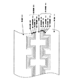
光ディスクには信号記録用のグルーブ・ランドと呼ばれる凹凸形状からなる案内溝が形成されており、記録再生を行うためのレーザー光を照射する側(基板側)から見て、遠くなる方向に凹形状にくぼんでいる側をランドと呼び、近くなる方向に凸形状に出っ張っている側をグルーブと呼ぶ。記録再生可能な案内溝のピッチ(トラックピッチ)によって、記録できる容量が決定される。例えばDVD+Rでは、グルーブにのみ情報を記録するグルーブ記録方式をとり、記録容量が4.7GBではトラックピッチが0.74μmである。
最近では、1枚の光ディスクの記憶容量を増加させるため、複数データ層システムが提案されている。2枚又はそれ以上のデータ層を有する光ディスクでは、レンズの焦点を変更することによって様々な層にアクセスすることができる。
特許文献1〜2には、有機色素層を用いた片面2層型の追記型ディスクについて記載されているが、情報層は有機色素層1層のみの繰り返しであり、反射率やDVD等との互換性を考慮した層構成ではない。
特許文献3〜4には片面2層型の追記型ディスクが記載されているが、これは記録層に無機材料を用いており、コストの面で問題がある。
また、これらの公知文献では、溝形状、プッシュプル値について全く触れていない。
An optical disk has a groove with a concave and convex shape called a groove land for signal recording, and is concave in a direction far from the laser irradiation side (substrate side) for recording and reproduction. The indented side is called a land, and the side protruding in a convex shape is called a groove. The recordable capacity is determined by the pitch (track pitch) of the guide grooves that can be recorded and reproduced. For example, DVD + R employs a groove recording method in which information is recorded only in the groove, and the track pitch is 0.74 μm when the recording capacity is 4.7 GB.
Recently, multiple data layer systems have been proposed to increase the storage capacity of a single optical disk. In an optical disc having two or more data layers, various layers can be accessed by changing the focal point of the lens.
Patent Documents 3 to 4 describe a single-sided, dual-layer write-once disc, but this uses an inorganic material for the recording layer, which is problematic in terms of cost.
In addition, these known documents do not mention the groove shape and push-pull value at all.
一方、相変化型の書換え可能なCD、DVDは、非晶質と結晶状態の屈折率差によって生じる反射率差及び位相差変化を利用して記録情報信号の検出を行う。通常の相変化型光記録媒体は、基板上に下部保護層、相変化型記録層、上部保護層、反射層を設けた構造を有し(これらを纏めて情報層と呼ぶ)、これら情報層の多重干渉を利用して反射率差及び位相差を制御し、CDやDVDとの互換性を持たせることができる。CD−RWにおいては、反射率を15〜25%程度に落とした範囲内ではCDと記録信号及び溝信号の互換性が確保でき、反射率の低さをカバーする増幅系を付加したCDドライブでは再生が可能である。
なお、相変化型光記録媒体は消去と再記録過程を1つの集束光ビームの強度変調のみによって行うことができるため、CD−RWや書換え可能DVD(DVD+RW、DVD−RWなど)等の相変化型光記録媒体において、記録とは記録と消去を同時に行うオーバーライト記録を含む。相変化を利用した情報の記録には、結晶、非晶質又はそれらの混合状態を用いることができ、複数の結晶相を用いることもできるが、現在実用化されている書き換え可能な相変化型光記録媒体は、未記録・消去状態を結晶状態とし、非晶質のマークを形成して記録するのが一般的である。
On the other hand, rewritable CDs and DVDs of phase change type detect a recording information signal by utilizing a reflectance difference and a phase difference change caused by a difference in refractive index between an amorphous state and a crystalline state. A normal phase change optical recording medium has a structure in which a lower protective layer, a phase change recording layer, an upper protective layer, and a reflective layer are provided on a substrate (collectively referred to as an information layer). Thus, it is possible to control the reflectivity difference and the phase difference by using multiple interferences, and to have compatibility with CDs and DVDs. In the CD-RW, the compatibility of the CD with the recording signal and the groove signal can be ensured within the range where the reflectance is reduced to about 15 to 25%, and the CD drive with the amplification system covering the low reflectance is added. Playback is possible.
Since phase change optical recording media can be erased and rerecorded only by intensity modulation of a single focused light beam, phase changes such as CD-RW and rewritable DVD (DVD + RW, DVD-RW, etc.) In the type optical recording medium, recording includes overwrite recording in which recording and erasing are performed simultaneously. For recording information using phase change, crystal, amorphous or a mixed state thereof can be used, and a plurality of crystal phases can be used. In general, an optical recording medium is recorded by forming an amorphous mark in an unrecorded / erased state in a crystalline state.
相変化型記録層の材料としてはカルコゲン元素、即ちS、Se、Teを含むカルコゲナイド系合金を用いることが多い。例えば、GeTe−Sb2Te3疑似二元合金を主成分とするGeSbTe系、InTe−Sb2Te3疑似二元合金を主成分とするInSbTe系、Sb0.7Te0.3共晶合金を主成分とするAgInSbTe系、GeSbTe系などである。特に、CD−RWなどの相変化型光記録媒体に広く用いられている材料の1つであるSb−Te共晶合金系記録材料は、GeTe−Sb2Te3疑似二元化合物系記録材料と比べて消去比が優れ且つ高感度であるために、記録マークのアモルファス部の輪郭が明確であるという点で優れたものとして知られている。
光ディスクには信号記録用のグルーブ・ランドと呼ばれる凹凸形状からなる案内溝が形成されており、記録再生を行うためのレーザー光を照射する側(基板側)から見て、遠くなる方向に凹形状に窪んでいる側をランドと呼び、近くなる方向に凸形状に出っ張っている側をグルーブと呼ぶ。記録容量は、記録再生可能な案内溝のピッチによって決定される。例えばDVD+RWでは、グルーブのみに情報を記録するグルーブ記録方式をとり、記録容量が4.7GBではトラックピッチが0.74μmである。また、グルーブとランドの両方に記録するランド・グルーブ記録方式も知られており、DVD−RAMはこの方式をとっている。
As a material for the phase change recording layer, a chalcogen element, that is, a chalcogenide alloy containing S, Se, or Te is often used. For example, a GeSbTe system mainly composed of GeTe-Sb 2 Te 3 pseudo binary alloy, an InSbTe system mainly composed of InTe-Sb 2 Te 3 pseudo binary alloy, and an Sb 0.7 Te 0.3 eutectic alloy. Examples thereof include an AgInSbTe system and a GeSbTe system. In particular, an Sb—Te eutectic alloy-based recording material, which is one of materials widely used for phase-change optical recording media such as CD-RW, is a GeTe—Sb 2 Te 3 pseudo binary compound-based recording material. Since the erasure ratio is superior and the sensitivity is higher than that, it is known that the contour of the amorphous portion of the recording mark is clear.
An optical disk has a groove with a concave and convex shape called a groove land for signal recording, and is concave in a direction far from the laser irradiation side (substrate side) for recording and reproduction. The side that is recessed in the direction is called a land, and the side that protrudes in a direction close to it is called a groove. The recording capacity is determined by the pitch of guide grooves that can be recorded and reproduced. For example, DVD + RW employs a groove recording method in which information is recorded only in the groove, and the track pitch is 0.74 μm when the recording capacity is 4.7 GB. Further, a land / groove recording method for recording on both the groove and the land is also known, and the DVD-RAM adopts this method.
光ディスクの記録密度を上げるためには、記録面内の密度を上げる他に、情報記録層の数を増やすことも考えられる。例えば、近年規格化及び商品化されたDVDは2層の情報記録層を有しており、ディスクの一方の側から、2層の情報記録層が読み出し可能な再生専用の光ディスクである。最近では、記録再生型のDVDとして、2層の情報記録層を持つ光ディスクが開発され、報告されている(例えば、特許文献7、8)。しかしながら未だ商品として実用化に至っていない。
片面2層型光ディスクの手前側に位置する情報層(第1情報層と呼ぶ)は、奥側の情報層(第2情報層と呼ぶ)の記録・再生のために、レーザー光の50%前後を透過させなければならない。また、感度よく記録するためには、第1情報層は40%前後レーザー光を吸収する必要がある。以上のことから、規格によると、追記型DVDの反射率は、例えばDVD+Rで45〜85%であり、書き換え型DVDの反射率は、例えばDVD+RWで30%以下であるが、片面2層型光ディスクの第1情報層では更に反射率が小さくなってしまうので、トラッキングが不安定になる恐れがある。一方、第2情報層も、第2情報層で反射された信号が、第1情報層で吸収されてしまうので、受光素子に届く割合は50%前後になってしまい、反射率が低下してしまうことは容易に想像がつく。
In order to increase the recording density of the optical disc, it is conceivable to increase the number of information recording layers in addition to increasing the density in the recording surface. For example, a DVD that has been standardized and commercialized in recent years has two information recording layers, and is a read-only optical disc from which two information recording layers can be read from one side of the disc. Recently, an optical disc having two information recording layers has been developed and reported as a recording / reproducing DVD (for example,
The information layer (referred to as the first information layer) located on the front side of the single-sided, dual-layer type optical disc is approximately 50% of the laser light for recording / reproduction of the information layer on the back side (referred to as the second information layer). Must be transparent. Further, in order to record with high sensitivity, the first information layer needs to absorb about 40% of laser light. From the above, according to the standard, the reflectivity of write-once DVD is 45 to 85% for DVD + R, for example, and the reflectivity of rewritable DVD is 30% or less for DVD + RW, for example. In the first information layer, since the reflectance is further reduced, tracking may be unstable. On the other hand, in the second information layer, the signal reflected by the second information layer is absorbed by the first information layer, so that the ratio reaching the light receiving element is about 50%, and the reflectance is lowered. It is easy to imagine.
以上のことから、片面2層型光ディスクでは、反射率、透過率及び吸収率をバランスよく設計する必要があるが、これには溝形状が大きく関係することが分った。また、後述するように、溝形状に大きく影響される片面2層型光ディスクのプッシュプル値の最適な範囲を本発明者等は見出した。プッシュプル信号は、光検出器の受光素子を半径方向に2分割した場合において、各々の出力をI1、I2としたとき、次の式で表される。式中、ppはピーク対ピーク、maxは最大値、minは最小値である。
(I1−I2)pp/[{(I1+I2)max+(I1+I2)min}/2]
追記型の片面2層型光ディスクが、例えば特許文献5〜6などに提案されているが、各層の光学特性を最適にし、かつ安定にトラッキングしながら良好に記録・再生するといった課題は考慮されておらず、プッシュプルについての記載はない。また、書き換え型の片面2層型光ディスクが特許文献7〜8に提案されているが、特許文献7には、溝形状に関する記載は一切なく、特許文献8には、案内溝の幅については規定されているものの、溝深さ、プッシュプル値については触れられていない。
From the above, in a single-sided dual-layer type optical disc, it is necessary to design the reflectivity, transmittance, and absorptance in a well-balanced manner. Further, as will be described later, the present inventors have found an optimum range of the push-pull value of the single-sided, double-layered optical disk that is greatly influenced by the groove shape. The push-pull signal is expressed by the following equation when the outputs of the photodetector are divided into two in the radial direction and the respective outputs are I1 and I2. In the formula, pp is peak-to-peak, max is a maximum value, and min is a minimum value.
(I1-I2) pp / [{(I1 + I2) max + (I1 + I2) min} / 2]
Write-once, single-sided, dual-layer optical discs have been proposed in, for example,
本発明は、上述のごとき実情に鑑みてなされたもので、安定にトラッキングでき、各情報層に対して良好に記録・再生を行なうことのできる片面2層型の追記型光記録媒体及び相変化型光記録媒体、並びにそれらの記録再生方法と装置の提供を目的とする。 The present invention has been made in view of the above circumstances, and is a single-sided dual-layer write-once optical recording medium and a phase change that can be stably tracked and can be recorded / reproduced with respect to each information layer satisfactorily. It is an object of the present invention to provide a type optical recording medium, and a recording and reproducing method and apparatus thereof.
本発明者等は、前記従来技術の問題点を解決するために鋭意検討を重ねた結果、次のような解決手段を見出した。即ち、上記課題は、次の1)〜11)の発明(以下、本発明1〜11という)によって解決される。
1) 第1基板と第2基板の間に第1情報層、中間層、第2情報層とが順次設けられ、各情報層は有機色素からなる追記型記録層を有し、かつ、記録トラックに沿ってグルーブが形成されており、第1基板から波長λのレーザー光を入射して光強度の2値以上の変調により情報の記録・再生を行なう片面2層光記録媒体であって、第1基板の屈折率をn1、中間層の屈折率をn2、第1情報層のグルーブの深さd1、グルーブの幅w1、トラックピッチp1、第2情報層のグルーブの深さd2、グルーブの幅w2、トラックピッチp2として、次の要件を満たすことを特徴とする光記録媒体。
4λ/16n1≦d1≦7λ/16n1
λ/16n2≦d2≦3λ/16n2、又は4λ/16n2≦d2≦7λ/16n2
0.2≦w1/p1≦0.55
0.2≦w2/p2≦0.55
2) 第1情報層の記録前のプッシュプル値をPP1、第2情報層の記録前のプッシュプル値をPP2として、次の要件を満たすことを特徴とする1)記載の光記録媒体。
0.30≦PP1≦0.70
0.25≦PP2≦0.60
0.6≦PP1/PP2≦1.4
3) 波長λの波長域の光に対する記録層単層での屈折率nが1.5≦n≦3.0で、消衰係数kが、0.02≦k≦0.2であることを特徴とする1)又2)記載の光記録媒体。
4) 未記録部での反射率が、18〜30%であることを特徴とする1)〜3)の何れかに記載の光記録媒体。
5) 第1基板と第2基板の間に第1情報層、中間層、第2情報層とが順次設けられ、各情報層は相変化記録材料からなる記録層を有し、かつ、記録トラックに沿ってグルーブが形成されており、第1基板から波長λのレーザー光を入射して光強度の2値以上の変調により情報の記録・再生を行なう片面2層光記録媒体であって、第1基板の屈折率をn1、中間層の屈折率をn2、第1情報層のグルーブの深さd1、グルーブの幅w1、トラックピッチp1、第2情報層のグルーブの深さd2、グルーブの幅w2、トラックピッチp2として、次の要件を満たすことを特徴とする光記録媒体。
λ/16n1≦d1≦3λ/16n1
λ/16n2≦d2≦3λ/16n2
0.2≦w1/p1≦0.6
0.2≦w2/p2≦0.6
6) 第1情報層の記録前のプッシュプル値をPP1、第2情報層の記録前のプッシュプル値をPP2として、次の要件を満たすことを特徴とする5)記載の光記録媒体。
0.30≦PP1≦0.70
0.25≦PP2≦0.60
0.6≦PP1/PP2≦1.4
7) 相変化記録層は、M1w(SbzTe100−z)100−w(w、zは原子%、0≦w<15、50<z<90、M1はIn,Ga,Ge,Sn,Si,Zr,Nb,Ta,V,Ag,Al,Pt,Pb,Cr,Co,O,S,Nからなる群より選ばれる少なくとも1種)で示される合金からなることを特徴とする5)又は6)記載の光記録媒体。
8) 相変化記録層は(Ge−M2)xSbyTe3+x(x、yは原子%、2≦x<22、2≦y≦4、M2はSn,Bi,Pbからなる群より選ばれる少なくとも1種)で示される合金であることを特徴とする5)又は6)記載の光記録媒体。
9) DPD信号が0.3以上であることを特徴とする1)〜8)の何れかに記載の光記録媒体。
10) 1)〜9)の何れかに記載の2層光記録媒体の各情報層に対し、波長350〜700nmの前記レーザー光を入射させて情報の記録・再生を行なうことを特徴とする光記録媒体の記録再生方法。
11) 1)〜9)の何れかに記載の2層光記録媒体の記録再生を行なう装置であって、波長350〜700nmのレーザー光を発生させる光源と、各情報層に基板側から入射した前記レーザー光によってマークを形成及び検出するための層認識手段及び層切り替え手段とを備えたことを特徴とする光記録媒体の記録再生装置。
As a result of intensive studies to solve the problems of the prior art, the present inventors have found the following solution. That is, the said subject is solved by the following invention of 1) -11) (henceforth this invention 1-11).
1) A first information layer, an intermediate layer, and a second information layer are sequentially provided between the first substrate and the second substrate, each information layer has a write-once recording layer made of an organic dye, and a recording track A single-sided, dual-layer optical recording medium on which information is recorded / reproduced by modulating a light intensity of at least two values when a laser beam having a wavelength λ is incident from a first substrate. The refractive index of one substrate is n 1 , the refractive index of the intermediate layer is n 2 , the groove depth d 1 of the first information layer, the groove width w 1 , the track pitch p 1 , and the groove depth of the second information layer. An optical recording medium satisfying the following requirements as d 2 , groove width w 2 , and track pitch p 2 .
4λ / 16n 1 ≦ d 1 ≦ 7λ / 16n 1
λ / 16n 2 ≦ d 2 ≦ 3λ / 16n 2 , or 4λ / 16n 2 ≦ d 2 ≦ 7λ / 16n 2
0.2 ≦ w 1 / p 1 ≦ 0.55
0.2 ≦ w 2 / p 2 ≦ 0.55
2) The optical recording medium according to 1), wherein the push pull value before recording of the first information layer is PP1 and the push pull value before recording of the second information layer is PP2, and satisfies the following requirements.
0.30 ≦ PP1 ≦ 0.70
0.25 ≦ PP2 ≦ 0.60
0.6 ≦ PP1 / PP2 ≦ 1.4
3) The refractive index n of the recording layer single layer for light in the wavelength range of wavelength λ is 1.5 ≦ n ≦ 3.0, and the extinction coefficient k is 0.02 ≦ k ≦ 0.2. An optical recording medium as described in 1) or 2).
4) The optical recording medium according to any one of 1) to 3), wherein a reflectance at an unrecorded portion is 18 to 30%.
5) A first information layer, an intermediate layer, and a second information layer are sequentially provided between the first substrate and the second substrate, each information layer has a recording layer made of a phase change recording material, and a recording track A single-sided, dual-layer optical recording medium on which information is recorded / reproduced by modulating a light intensity of at least two values when a laser beam having a wavelength λ is incident from a first substrate. The refractive index of one substrate is n 1 , the refractive index of the intermediate layer is n 2 , the groove depth d 1 of the first information layer, the groove width w 1 , the track pitch p 1 , and the groove depth of the second information layer. An optical recording medium satisfying the following requirements as d 2 , groove width w 2 , and track pitch p 2 .
λ / 16n 1 ≦ d 1 ≦ 3λ / 16n 1
λ / 16n 2 ≦ d 2 ≦ 3λ / 16n 2
0.2 ≦ w 1 / p 1 ≦ 0.6
0.2 ≦ w 2 / p 2 ≦ 0.6
6) The optical recording medium according to 5), wherein the push-pull value before recording of the first information layer is PP1 and the push-pull value before recording of the second information layer is PP2, and satisfies the following requirements.
0.30 ≦ PP1 ≦ 0.70
0.25 ≦ PP2 ≦ 0.60
0.6 ≦ PP1 / PP2 ≦ 1.4
7) M1w (SbzTe100-z) 100-w (w, z is atomic%, 0 ≦ w <15, 50 <z <90, M1 is In, Ga, Ge, Sn, Si, Zr) Nb, Ta, V, Ag, Al, Pt, Pb, Cr, Co, O, S, N)), or 5) or 6). The optical recording medium described.
8) The phase change recording layer is (Ge-M2) xSbyTe3 + x (x and y are atomic%, 2≤x <22, 2≤y≤4, M2 is at least 1 selected from the group consisting of Sn, Bi, Pb) The optical recording medium according to 5) or 6), wherein the optical recording medium is an alloy represented by Species).
9) The optical recording medium according to any one of 1) to 8), wherein the DPD signal is 0.3 or more.
10) Light that records and reproduces information by making the laser beam having a wavelength of 350 to 700 nm incident on each information layer of the two-layer optical recording medium according to any one of 1) to 9) A recording / reproducing method of a recording medium.
11) An apparatus for recording / reproducing the two-layer optical recording medium according to any one of 1) to 9), wherein the light source generates a laser beam having a wavelength of 350 to 700 nm, and enters each information layer from the substrate side. A recording / reproducing apparatus for an optical recording medium, comprising: a layer recognizing unit and a layer switching unit for forming and detecting a mark by the laser beam.
以下、上記本発明について詳しく説明する。
光学溝の読み取りはヘッド又はピックアップと一体的に移動する光スポットの反射光を受光する光ディスクの半径方向に2分割されたサーボ用光検出器により行われ、その第一の光検出部の出力I1と第2の光検出部の出力I2とが信号処理回路において演算処理される。
ビームの焦点位置がトラッキング中心からずれるとプッシュプル信号出力はそれに対応した曲線を示す。DVD+R、DVD+RWの規格では記録前のプッシュプル信号強度はそれぞれ0.30〜0.60、0.28〜0.56の範囲となっている。
しかし、第1情報層、第2情報層のプッシュプル信号強度が共に上記範囲になるようなディスクではモジュレーションの低下、繰り返し記録によるジッタの悪化、第2情報層の感度不足などが生じる。その理由は必ずしも明らかでないが、プッシュプル信号強度は溝形状により大きく影響を受けるので、恐らく溝形状と関係があると考えられる。溝深さが比較的浅い場合は、溝が浅くなるとプッシュプル信号強度は小さくなる。
Hereinafter, the present invention will be described in detail.
The reading of the optical groove is performed by a servo photodetector that is divided into two in the radial direction of the optical disk that receives the reflected light of the light spot that moves integrally with the head or the pickup, and the output I1 of the first light detector. And the output I2 of the second light detection unit are processed in the signal processing circuit.
When the focal position of the beam deviates from the tracking center, the push-pull signal output shows a corresponding curve. In the DVD + R and DVD + RW standards, the push-pull signal intensity before recording is in the range of 0.30 to 0.60 and 0.28 to 0.56, respectively.
However, in a disc in which the push-pull signal intensities of the first information layer and the second information layer are both in the above range, the modulation is lowered, the jitter is deteriorated due to repeated recording, and the sensitivity of the second information layer is insufficient. The reason for this is not necessarily clear, but the push-pull signal intensity is greatly influenced by the groove shape, and is probably related to the groove shape. When the groove depth is relatively shallow, the push-pull signal intensity decreases as the groove becomes shallower.
溝が浅すぎるとモジュレーションが取れなくなり、また隣接するトラックからの影響によりジッタが増加してしまい、溝が深すぎると反射率が低下したり、繰り返し記録によるジッタの増加が激しくなる。溝幅については、幅が広すぎるとやはりモジュレーションが取れなくなるし、繰り返し記録によるジッタの増加が激しい。幅が狭すぎるとトラッキングが不安定になってしまい、特に第1情報層で溝幅を狭くしすぎると、反射率と透過率のバランスが崩れてしまい、透過率が減少してしまうといった不具合が生じる。
そこで検討した結果、記録再生特性の優れた片面2層光ディスクとするには、レーザー光の波長をλnm、第1基板の屈折率をn1、中間層の屈折率をn2、第1情報層のグルーブの深さd1、グルーブの幅w1、トラックピッチp1、第2情報層のグルーブの深さd2、グルーブの幅w2、トラックピッチp2として、
追記型光記録媒体の場合には、次の要件を満たす必要があり、
4λ/16n1≦d1≦7λ/16n1
λ/16n2≦d2≦3λ/16n2、又は4λ/16n1≦d1≦7λ/16n1
0.2≦w1/p1≦0.55
0.2≦w2/p2≦0.55
相変化型光記録媒体の場合には、次の要件を満たす必要があることが分った。
λ/16n1≦d1≦3λ/16n1
λ/16n2≦d2≦3λ/16n2
0.2≦w1/p1≦0.6
0.2≦w2/p2≦0.6
If the groove is too shallow, modulation cannot be obtained, and jitter increases due to the influence from adjacent tracks. If the groove is too deep, the reflectivity decreases and the jitter increases repetitively. As for the groove width, if the width is too wide, the modulation cannot be obtained, and the increase in jitter due to repeated recording is severe. If the width is too narrow, tracking will become unstable. In particular, if the groove width is too narrow in the first information layer, the balance between reflectance and transmittance will be lost and the transmittance will be reduced. Arise.
As a result of the examination, in order to obtain a single-sided dual-layer optical disc with excellent recording / reproduction characteristics, the wavelength of the laser beam is λ nm, the refractive index of the first substrate is n 1 , the refractive index of the intermediate layer is n 2 , and the first information layer Groove depth d 1 , groove width w 1 , track pitch p 1 , groove depth d 2 of second information layer, groove width w 2 , track pitch p 2 ,
For write-once optical recording media, the following requirements must be met:
4λ / 16n 1 ≦ d 1 ≦ 7λ / 16n 1
λ / 16n 2 ≦ d 2 ≦ 3λ / 16n 2 , or 4λ / 16n 1 ≦ d 1 ≦ 7λ / 16n 1
0.2 ≦ w 1 / p 1 ≦ 0.55
0.2 ≦ w 2 / p 2 ≦ 0.55
It has been found that the following requirements must be satisfied in the case of a phase change type optical recording medium.
λ / 16n 1 ≦ d 1 ≦ 3λ / 16n 1
λ / 16n 2 ≦ d 2 ≦ 3λ / 16n 2
0.2 ≦ w 1 / p 1 ≦ 0.6
0.2 ≦ w 2 / p 2 ≦ 0.6
また、プッシュプル信号強度は、第1情報層の記録前のプッシュプル値をPP1、第2情報層の記録前のプッシュプル値をPP2として、次の要件を満たすとき総合的に優れた記録特性が得られた。
0.30≦PP1≦0.70
0.25≦PP2≦0.60
0.6≦PP1/PP2≦1.4
プッシュプルが上記範囲より大きいと、反射率が低くなるなどの原因で、各層を安定にフォーカシングするのが困難となる。また、プッシュプルが上記範囲より小さいと、トラッキングが不安定になったり、第1情報層の透過率が減少したりする。
また、PP1/PP2が0.6〜1.4の範囲であれば、例えばデータ読み出し中にピックアップが第1情報層から第2情報層へジャンプした際に、トラッキングが外れることなくスムーズに読み出しを行なうことができる。
The push-pull signal strength is generally excellent when the following information is satisfied when the push-pull value before recording of the first information layer is PP1 and the push-pull value before recording of the second information layer is PP2. was gotten.
0.30 ≦ PP1 ≦ 0.70
0.25 ≦ PP2 ≦ 0.60
0.6 ≦ PP1 / PP2 ≦ 1.4
If the push-pull is larger than the above range, it is difficult to focus each layer stably due to a decrease in reflectance. If the push-pull is smaller than the above range, tracking becomes unstable or the transmittance of the first information layer decreases.
Further, if PP1 / PP2 is in the range of 0.6 to 1.4, for example, when the pickup jumps from the first information layer to the second information layer during data reading, the reading is smoothly performed without losing tracking. Can be done.
プッシュプル値には、グルーブ面からの反射光とランド部からの反射光の位相差が深く関わっているため、グルーブの溝深さの最適値がレーザー波長λとの関係式で表せることは従来から知られているが、本発明者等は、鋭意検討の結果、本発明に係る2層光記録媒体の場合、レーザー波長λ=350〜750nmの範囲において、本発明1又は5で規定する範囲が好ましいことを見出した。この知見は、前述したように公知文献には全く記載されていない新規な事項である。
また、本発明1又は5はレーザー波長λを含む式で規定されているが、一般に光記録媒体は、使用する記録再生用レーザー波長の範囲を特定して設計されるものであり、350〜750nmの範囲内であれば、光記録媒体の種類によって特定される記録再生用レーザー波長によりグルーブの深さが決まるのであるから、レーザー波長λを構成要件に含むことにより光記録媒体としての構成が不明瞭になることはない。
とりわけ、本発明は、DVD+Rに用いられるような赤色レーザーの波長630〜680nm、あるいは青色レーザーの波長390〜420nmの範囲において、本発明1又は5で規定する範囲にあることが好ましい。
Since the push-pull value is deeply related to the phase difference between the reflected light from the groove surface and the reflected light from the land portion, the optimum value of the groove depth of the groove can be expressed by a relational expression with the laser wavelength λ. In the case of the two-layer optical recording medium according to the present invention, as a result of intensive studies, the present inventors have found that the range specified by the
In addition, the
In particular, the present invention is preferably in the range defined by the
反射率については、追記型光記録媒体の場合、片面2層型DVD−ROMとの互換性から、未記録部の反射率を18〜30%であることが好ましく、18〜25%が特に好ましい。また相変化型光記録媒体の場合、ディスクの溝のない部分(鏡面部)の反射率が20%を越えると記録信号のコントラストの大きなディスクを得ることが困難となる。一方、反射率が小さいと全ての信号強度が小さくなることになるので、反射率は小さすぎてもいけない。従って鏡面部の反射率は4〜20%が好ましく、6〜12%が特に好ましい。
DPD信号は、追記型の場合も相変化型の場合も、0.3以上であることが好ましい。再生専用の光ディスク装置におけるトラッキング方式は、DPD法(Differential Phase Detection:位相差検出法)が採用されている。従って、DPD信号が0.3より小さいと、再生専用の光ディスク装置でのトラッキングが不安定になり、トラッキング外れを起こし易くなる傾向にある。
Regarding the reflectance, in the case of a write once optical recording medium, the reflectance of the unrecorded portion is preferably 18 to 30%, and particularly preferably 18 to 25%, in view of compatibility with the single-sided dual layer DVD-ROM. . In the case of a phase change type optical recording medium, if the reflectivity of the portion without a groove (mirror surface portion) of the disc exceeds 20%, it becomes difficult to obtain a disc having a high recording signal contrast. On the other hand, if the reflectance is small, all signal intensities will be small, so the reflectance should not be too small. Therefore, the reflectance of the mirror surface portion is preferably 4 to 20%, particularly preferably 6 to 12%.
The DPD signal is preferably 0.3 or more in both the write-once type and the phase change type. As a tracking method in a reproduction-only optical disc apparatus, a DPD method (Differential Phase Detection) is adopted. Therefore, if the DPD signal is smaller than 0.3, tracking in the read-only optical disk apparatus becomes unstable, and tends to cause off-tracking.
図1は、本発明の一実施形態に係わる片面2層型の追記型光記録媒体の概略断面図である。
図1に示す記録再生型の光記録媒体は、2つの情報層を有する。各情報層は、有機色素材料を用いて形成される。各情報層への情報の記録は、第1基板側からレーザー光を入射させ、マークと呼ばれるパターンの記録により行われる。
より具体的には、案内溝を有する第1基板101上に、第1情報層100を形成する。第1情報層100は、第1記録層103単層でもよいし、第1記録層の上に第1反射層105が積層された構成でもよい。更に第1反射層の上に透明な第1熱拡散層106を設けてもよい。また、第1記録層103と第1基板101の間に下引き層又は保護層(図示せず)を設けてもよく、機能向上のためにそれらを積層化した構成としてもよい。
一方、第2情報層200は、案内溝を有する第2基板201上に形成される。第2情報層200は、第2記録層203単層でもよいし、第2反射層205と第2記録層203とが積層された構成でもよい。また、第2記録層203と中間層300の間に下引き層又は保護層(図示せず)を設けてもよく、機能向上のためにそれらを積層化した構成としてもよい。
第1情報層100と第2情報層200とは、略透明な中間層300(接着層)により所定の距離で隔てられ、対向した状態で貼り合わされている。
また、製造方法によっては、中間層300に案内溝を形成し、その上に第2情報層200を形成しても構わない。
FIG. 1 is a schematic cross-sectional view of a single-sided, two-layer write once optical recording medium according to an embodiment of the present invention.
The recording / reproducing optical recording medium shown in FIG. 1 has two information layers. Each information layer is formed using an organic dye material. Information is recorded on each information layer by making a laser beam incident from the first substrate side and recording a pattern called a mark.
More specifically, the
Meanwhile, the
The
Further, depending on the manufacturing method, a guide groove may be formed in the intermediate layer 300, and the
その材料としては、ポリカーボネート、アクリル樹脂、ポリオレフィンなどの透明樹脂、或いは透明ガラスを用いることができる。中でも、ポリカーボネート樹脂はCDにおいて最も広く用いられているなどの実績もあり、また安価でもあるため最も好ましい材料である。第1基板には、必要に応じて記録再生光を案内するピッチの溝を設けてもよい。また第1基板の厚さは、0.6mm±0.1mm程度が好ましい。
第2基板の材料としては、第1基板と同じ材料を用いても良いが、記録再生光に対して不透明な材料を用いても良く、第1基板とは材質、溝形状が異なっても良い。第2基板の厚さは特に限定されないが、第1基板との合計の厚さが1.2mmになるように第2基板の厚さを選択することが好ましい。また、第2情報層を形成する側に案内溝を設けてもよい。
As the material, a transparent resin such as polycarbonate, acrylic resin, polyolefin, or transparent glass can be used. Among them, polycarbonate resin is the most preferable material because it has a track record of being most widely used in CD and is inexpensive. The first substrate may be provided with a groove having a pitch for guiding the recording / reproducing light as required. The thickness of the first substrate is preferably about 0.6 mm ± 0.1 mm.
As the material of the second substrate, the same material as that of the first substrate may be used, but a material opaque to the recording / reproducing light may be used, and the material and groove shape may be different from those of the first substrate. . The thickness of the second substrate is not particularly limited, but it is preferable to select the thickness of the second substrate so that the total thickness with the first substrate is 1.2 mm. A guide groove may be provided on the side on which the second information layer is formed.
中間層は、記録再生のために照射する光の波長における光吸収が小さい方が好ましく、材料としては、成形性、コストの点で樹脂が好適であり、紫外線硬化性樹脂、遅効性樹脂、熱可塑性樹脂などを用いることができる。また、光ディスク貼り合わせ用の両面テープ(例えば日東電工社製の粘着シートDA−8320)なども用いることができる。また、中間層には、第1基板と同様に、記録再生光を案内する溝を設けてもよい。
中間層は、記録再生を行う際に、ピックアップが第1情報層と第2情報層とを識別して光学的に分離できるようにするものであり、その厚さは10〜70μmが好ましい。10μmより薄いと、層間クロストークが生じ、また70μmより厚いと、第2情報層を記録再生する際に球面収差が発生し、記録再生が困難になる傾向がある。より好ましい範囲は40〜70μmである。
The intermediate layer preferably has smaller light absorption at the wavelength of light irradiated for recording / reproduction, and the material is preferably a resin in terms of moldability and cost, such as an ultraviolet curable resin, a slow-acting resin, and a heat A plastic resin or the like can be used. In addition, a double-sided tape for bonding optical disks (for example, an adhesive sheet DA-8320 manufactured by Nitto Denko Corporation) can be used. Further, the intermediate layer may be provided with a groove for guiding the recording / reproducing light, like the first substrate.
The intermediate layer is a layer that enables the pickup to discriminate between the first information layer and the second information layer and optically separate them during recording and reproduction, and the thickness is preferably 10 to 70 μm. When the thickness is less than 10 μm, interlayer crosstalk occurs. When the thickness is greater than 70 μm, spherical aberration occurs when recording / reproducing the second information layer, and recording / reproduction tends to be difficult. A more preferable range is 40 to 70 μm.
次に、第1記録層103及び第2記録層203について説明する。
光記録媒体の記録層を構成するのに必要な項目として光学特性が挙げられる。光学特性として必要な条件は、記録再生波長において短波長側に大きな吸収帯を有し、かつ記録再生波長が該吸収帯の長波長端近傍にあることである。これは、記録再生波長で大きな屈折率と消衰係数を有することを意味する。具体的には、記録再生波長における記録層単層の屈折率nが、1.5≦n≦3.0で、消衰係数kが、0.02≦k≦0.2の範囲にあることが好ましい。この条件を満足すると、高感度、高モジュレーションで安定した記録・再生が可能となる。しかし、nが1.5未満では、十分な光学的変化を得難いため、記録変調度が低くなり好ましくなく、nが3.0を超えると、波長依存性が高くなり過ぎるため、記録再生波長領域であってもエラーとなってしまうため好ましくない。また、kが0.02未満では、記録感度が悪くなるため好ましくなく、kが0.2を超えると、18%以上の反射率を得ることが困難となり、特に第1情報層では、透過率が低くなりすぎて第2情報層の記録感度が悪くなるため好ましくない。
Next, the first recording layer 103 and the second recording layer 203 will be described.
Optical characteristics can be mentioned as an item necessary for constituting the recording layer of the optical recording medium. A necessary condition for the optical characteristics is that the recording / reproducing wavelength has a large absorption band on the short wavelength side, and the recording / reproducing wavelength is in the vicinity of the long wavelength end of the absorption band. This means that it has a large refractive index and extinction coefficient at the recording / reproducing wavelength. Specifically, the refractive index n of the recording layer single layer at the recording / reproducing wavelength is 1.5 ≦ n ≦ 3.0, and the extinction coefficient k is in the range of 0.02 ≦ k ≦ 0.2. Is preferred. If this condition is satisfied, stable recording / reproduction with high sensitivity and high modulation becomes possible. However, if n is less than 1.5, it is difficult to obtain a sufficient optical change, so that the recording modulation degree is low, which is not preferable. If n is more than 3.0, the wavelength dependency becomes too high. However, it is not preferable because an error occurs. Further, if k is less than 0.02, it is not preferable because the recording sensitivity deteriorates. If k exceeds 0.2, it is difficult to obtain a reflectance of 18% or more. Is undesirably low because the recording sensitivity of the second information layer deteriorates.
次に、記録層に使用可能な有機色素材料の具体例としては、アゾ金属キレート色素、ホルマザン金属キレート色素、ジピロメテン金属キレート色素、ポリメチン色素、スクアリリウム色素、アザアヌレン色素等が挙げられ、好ましいのは、金属キレート色素、トリメチンシアニン色素、スクアリリウム色素、テトラアザポルフィリン色素である。
アゾ金属キレート色素としては、アゾ結合を挟む両側のアゾ化合物形成ユニットが、置換・未置換の芳香環、ピリジン残基、ピリミジン残基、ピラジン残基、ピリダジン残基、トリアジン残基、イミダゾール残基、トリアゾール残基、ピラゾール残基、チアゾール残基、イソチアゾール残基、ベンズチアゾール残基等の組み合わせからなるアゾ化合物の金属キレート化合物が特に好ましい。
Next, specific examples of organic dye materials that can be used in the recording layer include azo metal chelate dyes, formazan metal chelate dyes, dipyrromethene metal chelate dyes, polymethine dyes, squarylium dyes, azaannulene dyes, and the like. Metal chelate dyes, trimethine cyanine dyes, squarylium dyes, tetraazaporphyrin dyes.
As azo metal chelate dyes, the azo compound forming units on both sides of the azo bond are substituted / unsubstituted aromatic rings, pyridine residues, pyrimidine residues, pyrazine residues, pyridazine residues, triazine residues, imidazole residues. A metal chelate compound of an azo compound comprising a combination of triazole residue, pyrazole residue, thiazole residue, isothiazole residue, benzthiazole residue and the like is particularly preferable.
また、ホルマザン金属キレート色素としては、下記〔化1〕の一般式で示されるホルマザン化合物と2価の金属原子とのキレート化合物が好ましい。

ジピロメテン金属キレート色素としては、下記〔化2〕の一般式で示されるジピロメテン化合物と2価の金属原子とのキレート化合物が好ましい。
上記アゾ化合物、ホルマザン化合物、ジピロメテン化合物とキレート化合物を形成する金属としては、例えば、Ni、Co、Cu、Mn、V、Zn、Fe、Cr、Al等が挙げられ、製造上及びディスク特性上から、特にNi、Co、Cu、Mn、Vが好ましい。
As the dipyrromethene metal chelate dye, a chelate compound of a dipyrromethene compound represented by the following general formula [Chemical Formula 2] and a divalent metal atom is preferable.
Examples of the metal that forms a chelate compound with the azo compound, formazan compound, and dipyrromethene compound include Ni, Co, Cu, Mn, V, Zn, Fe, Cr, and Al. From the viewpoint of manufacturing and disk characteristics. In particular, Ni, Co, Cu, Mn, and V are preferable.
ポリメチン色素としては、530〜600nmに吸収帯を有するものならば使用可能であるが、中でもトリメチンシアニン色素が好ましく、トリメチン鎖の両端が置換・未置換のインドレニン、ベンズインドレニンのものが特に好ましく、カウンターアニオンとしては、ハロゲンアニオン、ClO4 −、BF4 −、PF6 −、SbF6 −等の他にニッケルジチオレート錯体に代表される各種金属キレートアニオンでもよい。
スクアリリウム色素としては、スクアレン環の両端が置換・未置換のインドレニン、ベンズインドレニン、ピラゾール、カルバゾール、キノキサリン、イソインドール、芳香環、置換アミノ基残基のうちの組み合わせからなるものが好ましい。
アザアヌレン色素としては、各々特定の置換基を有するフタロシアニン、ナフタロシアニン、テトラピラジノポルフィラジン、テトラピリジノポルフィラジン、テトラアザポルフィリン等が挙げられるが、このうち特に好ましいのはテトラアザポルフィリンであり、次いでテトラピリジノポルフィラジン、テトラピラジノポルフィラジン、フタロシアニンの順で好ましい。
上記した色素の熱分解特性としては、色素単独で用いる場合も混合して用いる場合もその記録材料の分解開始温度が360℃以下であることが好ましく、特に100〜350℃が好ましい。分解温度が360℃を超えると記録時のピット形成がうまく行われず、ジッタ特性が悪くなる。また100℃未満であると今度はディスクの保存安定性が悪化する。
As the polymethine dye, any dye having an absorption band at 530 to 600 nm can be used. Among them, a trimethine cyanine dye is preferable, and in particular, a trimethine chain having both substituted and unsubstituted indolenine and benzindolenin is particularly preferred. Preferably, the counter anion may be a halogen anion, ClO 4 − , BF 4 − , PF 6 − , SbF 6 − or the like, or various metal chelate anions typified by a nickel dithiolate complex.
The squarylium dye is preferably one composed of a combination of substituted and unsubstituted indolenine, benzindolenin, pyrazole, carbazole, quinoxaline, isoindole, aromatic ring, and substituted amino group residues at both ends of the squalene ring.
Examples of the azaannulene dye include phthalocyanine, naphthalocyanine, tetrapyrazinoporphyrazine, tetrapyridinoporphyrazine, tetraazaporphyrin, etc. each having a specific substituent, and among these, tetraazaporphyrin is particularly preferable, Next, tetrapyridinoporphyrazine, tetrapyrazinoporphyrazine, and phthalocyanine are preferable in this order.
As the above-mentioned thermal decomposition characteristics of the dye, whether the dye is used alone or mixed, the decomposition start temperature of the recording material is preferably 360 ° C. or less, particularly preferably 100 to 350 ° C. If the decomposition temperature exceeds 360 ° C., pit formation at the time of recording is not performed well, and the jitter characteristics are deteriorated. If the temperature is lower than 100 ° C., the storage stability of the disk deteriorates.
また、上記色素は、光学特性、記録感度、信号特性などの向上の目的で他の有機色素及び金属、金属化合物と混合又は積層化して用いてもよい。
このような有機色素の例としては、(ポリ)メチン色素、ナフタロシアニン系、フタロシアニン系、スクアリリウム系、クロコニウム系、ピリリウム系、ナフトキノン系、アントラキノン系(インダンスレン系)、キサンテン系、トリフェニルメタン系、アズレン系、テトラヒドロコリン系、フェナンスレン系、トリフェノチアジン系各染料及び、金属錯体化合物などが挙げられる。
金属、金属化合物の例としては、In、Te、Bi、Se、Sb、Ge、Sn、Al、Be、TeO2、SnO、As、Cdなどが挙げられ、それぞれを分散混合又は積層の形態で用いることができる。
更に、上記染料中に高分子材料、例えばアイオノマー樹脂、ポリアミド樹脂、ビニル系樹脂、天然高分子、シリコーン、液状ゴムなどの種々の材料、或いはシランカップリング剤などを分散混合してもよいし、特性改良の目的で安定剤(例えば遷移金属錯体)、分散剤、難燃剤、滑剤、帯電防止剤、界面活性剤、可塑剤などを一緒に用いてもよい。
The above dye may be mixed or laminated with other organic dyes, metals and metal compounds for the purpose of improving optical characteristics, recording sensitivity, signal characteristics and the like.
Examples of such organic dyes include (poly) methine dyes, naphthalocyanine series, phthalocyanine series, squarylium series, croconium series, pyrylium series, naphthoquinone series, anthraquinone series (indanthrene series), xanthene series, triphenylmethane -Based, azulene-based, tetrahydrocholine-based, phenanthrene-based, triphenothiazine-based dyes, metal complex compounds, and the like.
Examples of metals and metal compounds include In, Te, Bi, Se, Sb, Ge, Sn, Al, Be, TeO 2 , SnO, As, Cd, etc., each of which is used in the form of dispersion mixing or lamination. be able to.
Furthermore, various materials such as ionomer resin, polyamide resin, vinyl resin, natural polymer, silicone, liquid rubber, or a silane coupling agent may be dispersed and mixed in the dye, For the purpose of improving characteristics, stabilizers (for example, transition metal complexes), dispersants, flame retardants, lubricants, antistatic agents, surfactants, plasticizers and the like may be used together.
有機色素記録層の形成方法としては、蒸着、スパッタリング、CVD(化学的気相成長法)、溶剤塗布などの通常の手段を用いることができる。
塗布法を用いる場合には、上記染料などを有機溶剤に溶解し、スプレー、ローラーコーティグ、ディピング、スピンコーティングなどの慣用のコーティング法によって行うことができる。用いられる有機溶媒としては、一般にメタノール、エタノール、イソプロパノールなどのアルコール類;アセトン、メチルエチルケトン、シクロヘキサノンなどのケトン類;N,N−ジメチルホルムアミド、N,N−ジメチルアセトアミドなどのアミド類;ジメチルスルホキシドなどのスルホキシド類;テトラヒドロフラン、ジオキサン、ジエチルエーテル、エチレングリコールモノメチルエーテルなどのエーテル類;酢酸メチル、酢酸エチルなどのエステル類;クロロホルム、塩化メチレン、ジクロルエタン、四塩化炭素、トリクロルエタンなどの脂肪族ハロゲン化炭化水素類;ベンゼン、キシレン、モノクロルベンゼン、ジクロルベンゼンなどの芳香族類;メトキシエタノール、エトキシエタノールなどのセロソルブ類;ヘキサン、ペンタン、シクロヘキサン、メチルシクロヘキサンなどの炭化水素類などが挙げられる。
記録層の膜厚は10nm〜10μm、好ましくは20〜200nmとする。
As a method for forming the organic dye recording layer, usual means such as vapor deposition, sputtering, CVD (chemical vapor deposition), and solvent coating can be used.
When the coating method is used, the above-described dye or the like can be dissolved in an organic solvent, and the coating can be performed by a conventional coating method such as spraying, roller coating, dipping, or spin coating. As the organic solvent to be used, alcohols such as methanol, ethanol and isopropanol; ketones such as acetone, methyl ethyl ketone and cyclohexanone; amides such as N, N-dimethylformamide and N, N-dimethylacetamide; dimethyl sulfoxide and the like Sulfoxides; Ethers such as tetrahydrofuran, dioxane, diethyl ether, and ethylene glycol monomethyl ether; Esters such as methyl acetate and ethyl acetate; Aliphatic halogenated hydrocarbons such as chloroform, methylene chloride, dichloroethane, carbon tetrachloride, and trichloroethane Aromatics such as benzene, xylene, monochlorobenzene and dichlorobenzene; cellosolves such as methoxyethanol and ethoxyethanol; hexane and pen Down, cyclohexane, and hydrocarbons such as methylcyclohexane.
The thickness of the recording layer is 10 nm to 10 μm, preferably 20 to 200 nm.
下引き層は、(1)接着性の向上、(2)水又はガスなどのバリアー、(3)記録層の保存安定性の向上、(4)反射率の向上、(5)溶剤からの基板の保護、(6)案内溝、案内ピット、プレフォーマットの形成などを目的として使用される。
(1)の目的に対しては、例えばアイオノマー樹脂、ポリアミド樹脂、ビニル樹脂、天然樹脂、天然高分子、シリコーン、液状ゴムなどの種々の高分子化合物、及びシランカップリング剤などを用いることができ、(2)及び(3)の目的に対しては、上記高分子材料以外に、SiO、MgF、SiO2、TiO、ZnO、TiN、SiNなどの無機化合物を用いることができ、更に、Zn、Cu、Ni、Cr、Ge、Se、Au、Ag、Alなどの金属又は半金属を用いることができる。(4)の目的に対しては、Al、Au、Ag等の金属や、メチン染料、キサンテン系染料などの金属光沢を有する有機薄膜を用いることができる。(5)及び(6)の目的に対しては紫外線硬化性樹脂、熱硬化性樹脂、熱可塑性樹脂等を用いることができる。
下引き層の膜厚としては0.01〜30μm、好ましくは0.05〜10μmが適当である。
The undercoat layer consists of (1) improved adhesion, (2) a barrier such as water or gas, (3) improved storage stability of the recording layer, (4) improved reflectance, and (5) a substrate from a solvent. And (6) formation of guide grooves, guide pits, and preformats.
For the purpose of (1), for example, various polymer compounds such as ionomer resin, polyamide resin, vinyl resin, natural resin, natural polymer, silicone, liquid rubber, and silane coupling agent can be used. For the purposes of (2) and (3), in addition to the polymer material, inorganic compounds such as SiO, MgF, SiO 2 , TiO, ZnO, TiN, SiN can be used, and Zn, Metals or semimetals such as Cu, Ni, Cr, Ge, Se, Au, Ag, and Al can be used. For the purpose of (4), metals such as Al, Au and Ag, and organic thin films having metallic luster such as methine dyes and xanthene dyes can be used. For the purposes (5) and (6), an ultraviolet curable resin, a thermosetting resin, a thermoplastic resin, or the like can be used.
The thickness of the undercoat layer is 0.01 to 30 μm, preferably 0.05 to 10 μm.
反射層の材料としては、単体で高反射率の得られる腐食され難い金属、半金属等が挙げられ、具体例としてはAu、Ag、Cr、Ni、Al、Fe、Snなどが挙げられるが、反射率、生産性の点からAu、Ag、Alが最も好ましい。また、これらの金属、半金属は単独で用いても2種の合金として用いてもよい。
特に第1情報層は高い透過率が必要とされるため、第1反射層には、屈折率が低く熱伝導率の高いAg又はその合金を用いることが好ましい。
反射層の膜形成法としては蒸着、スッパタリングなどが挙げらる。
第2反射層の膜厚は3〜500nm、好ましくは3〜300nmとする。第1反射層に関しては3〜20nmが好ましい。3nm未満にすると、厚さが均一で緻密な膜を作ることが困難になる。第2反射層の膜厚が500nmを超えると、第2反射層と第2記録層との界面の形状が、基板の溝形状と大きく異なってしまう。また、第1反射層の膜厚が20nmを超えると、透過率が減少して第2情報層の感度が低下する傾向にある。
Examples of the material for the reflective layer include metals and semi-metals that are highly corrosive and are not easily corroded, and specific examples include Au, Ag, Cr, Ni, Al, Fe, and Sn. Au, Ag, and Al are most preferable from the viewpoint of reflectance and productivity. These metals and metalloids may be used alone or as two kinds of alloys.
In particular, since the first information layer requires high transmittance, it is preferable to use Ag or an alloy thereof having a low refractive index and a high thermal conductivity for the first reflective layer.
Examples of the method for forming the reflective layer include vapor deposition and sputtering.
The thickness of the second reflective layer is 3 to 500 nm, preferably 3 to 300 nm. The first reflective layer is preferably 3 to 20 nm. If the thickness is less than 3 nm, it becomes difficult to form a dense film having a uniform thickness. When the thickness of the second reflective layer exceeds 500 nm, the shape of the interface between the second reflective layer and the second recording layer is greatly different from the groove shape of the substrate. Moreover, when the film thickness of the first reflective layer exceeds 20 nm, the transmittance tends to decrease and the sensitivity of the second information layer tends to decrease.
保護層は、記録層(反射吸収層)の熱的ダメージからの保護、記録層(反射吸収層)の保存安定性の向上、反射率の向上、クロストーク軽減等を目的として使用される。これらの目的に対しては、前記下引き層において示した材料を用いることができる。また、無機材料として、SiO、SiO2なども用いることができ、有機材料としてポリメチルアクリレート樹脂、ポリカーボネート樹脂、エポキシ樹脂、ポリスチレン樹脂、ポリエステル樹脂、ビニル樹脂、セルロース樹脂、脂肪族炭化水素樹脂、天然ゴム、スチレンブタジエン樹脂、クロロプレンゴム、ワックス、アルキッド樹脂、乾性油、ロジン等の熱軟化性、熱溶融性樹脂も用いることができる。上記材料のうち最も好ましいのはZnS、SiO2などの無機材料である。
保護層の膜厚は0.01〜30μm、好ましくは0.05〜10μmとする。
なお、下引き層や保護層には、記録層の場合と同様に、安定剤、分散剤、難燃剤、滑剤、帯電防止剤、界面活性剤、可塑剤等を含有させることができる。
The protective layer is used for the purpose of protecting the recording layer (reflection / absorption layer) from thermal damage, improving the storage stability of the recording layer (reflection / absorption layer), improving the reflectance, and reducing crosstalk. For these purposes, the materials shown in the undercoat layer can be used. In addition, SiO, SiO 2 or the like can be used as an inorganic material, and polymethyl acrylate resin, polycarbonate resin, epoxy resin, polystyrene resin, polyester resin, vinyl resin, cellulose resin, aliphatic hydrocarbon resin, natural material can be used as organic material. Thermosoftening and heat melting resins such as rubber, styrene butadiene resin, chloroprene rubber, wax, alkyd resin, drying oil and rosin can also be used. Of the above materials, inorganic materials such as ZnS and SiO 2 are most preferable.
The thickness of the protective layer is 0.01 to 30 μm, preferably 0.05 to 10 μm.
The undercoat layer and the protective layer can contain a stabilizer, a dispersant, a flame retardant, a lubricant, an antistatic agent, a surfactant, a plasticizer, and the like, as in the recording layer.
本発明の片面2層型の追記型光記録媒体では、第1反射層の上に第1熱拡散層を設けてもよい。第1反射層は、透過率の観点から非常に薄くなければならないが、第1反射層が薄いと熱容量が不足して、熱が有機色素記録層に篭り、微小マークの形成が難しくなる。そこで、第1反射層の熱容量不足を補うために第1熱拡散層を設ける。第1熱拡散層としては、レーザー照射された有機色素記録層を急冷させるために、熱伝導率が大きいことが望まれる。また、奥側の情報層を記録再生できるように、レーザー波長での吸収率が小さいことも望まれる。
情報の記録再生に用いるレーザー波長において、消衰係数が0.5以下であることが好ましく、更に好ましくは0.3以下である。0.5より大きいと第1情報層での吸収率が増大し、第2情報層の記録再生が困難になる。
また、情報の記録再生に用いるレーザー波長において、屈折率は1.6以上であることが好ましい。これより小さいと、第1情報層の透過率を大きくすることが困難になる。
In the single-sided two-layer write-once optical recording medium of the present invention, a first thermal diffusion layer may be provided on the first reflective layer. The first reflective layer must be very thin from the viewpoint of transmittance. However, if the first reflective layer is thin, the heat capacity is insufficient, and heat is applied to the organic dye recording layer, making it difficult to form micro marks. Therefore, a first thermal diffusion layer is provided to make up for the lack of heat capacity of the first reflective layer. As the first thermal diffusion layer, it is desirable that the thermal conductivity is high in order to quench the organic dye recording layer irradiated with the laser. It is also desirable that the absorption rate at the laser wavelength is small so that the information layer on the back side can be recorded and reproduced.
At the laser wavelength used for recording / reproducing information, the extinction coefficient is preferably 0.5 or less, more preferably 0.3 or less. If it is greater than 0.5, the absorptance in the first information layer increases, and recording / reproduction of the second information layer becomes difficult.
The refractive index is preferably 1.6 or more at the laser wavelength used for recording / reproducing information. If it is smaller than this, it becomes difficult to increase the transmittance of the first information layer.
以上のことから、窒化物、酸化物、硫化物、窒酸化物、炭化物、弗化物の少なくとも1種を含むことが好ましい。例えば、AlN、Al2O3、SiC、SiN、SnO2、In2O3、ZnO、ITO(酸化インジウム−酸化スズ)、IZO(酸化インジウム−酸化亜鉛)、ATO(酸化スズ−アンチモン)、DLC(ダイアモンドライクカーボン)、BNなどが挙げられる。
第1熱拡散層は、各種気相成長法、例えば真空蒸着法、スパッタリング法、プラズマCVD法、光CVD法、イオンプレーティング法、電子ビーム蒸着法などによって形成できる。中でも、スパッタリング法が、量産性、膜質等に優れている。
第1熱拡散層の膜厚は、10〜200nmが好ましい。10nmより薄いと、放熱効果が得られなくなる。200nmより厚いと、応力が大きくなり、繰り返し記録特性が低下するばかりでなく、量産性にも問題が生じる。
From the above, it is preferable that at least one of nitride, oxide, sulfide, nitride oxide, carbide and fluoride is included. For example, AlN, Al 2 O 3 , SiC, SiN, SnO 2 , In 2 O 3 , ZnO, ITO (indium oxide-tin oxide), IZO (indium oxide-zinc oxide), ATO (tin oxide-antimony), DLC (Diamond like carbon), BN, etc. are mentioned.
The first thermal diffusion layer can be formed by various vapor deposition methods such as vacuum deposition, sputtering, plasma CVD, photo CVD, ion plating, and electron beam deposition. Among these, the sputtering method is excellent in mass productivity and film quality.
The thickness of the first thermal diffusion layer is preferably 10 to 200 nm. If it is thinner than 10 nm, the heat dissipation effect cannot be obtained. If it is thicker than 200 nm, the stress increases, and not only the repeated recording characteristics deteriorate, but also a problem arises in mass productivity.
図2は、本発明の他の実施形態に係わる片面2層型の相変化型光記録媒体の概略断面図である。図2に示す記録再生型の光記録媒体は2つの情報層を有する。各情報層は非晶質と結晶の間で光学的特性が変化する材料(いわゆる相変化記録材料)を用いて形成される。各情報層への情報の記録は、図1の場合と同様に、第1基板からレーザー光を入射させ、マークと呼ばれるパターンの記録により行われる。より具体的には、案内溝を有する第1基板101に、第1情報層100を形成する。第1情報層は、少なくとも、透明な第1下部保護層102と透明な第1上部保護層104とで挟むように形成された相変化記録材料からなる第1記録層103、及び半透明な第1反射層105が積層されて構成されている。反射層105の上に更に透明な第1熱拡散層106を設けてもよい。
一方、第2情報層200は、案内溝を有する第2基板201に形成される。第2情報層200は、第2反射層205、透明な第2下部保護層202と透明な第2上部保護層204で挟むように形成された相変化記録材料からなる第2記録層203が積層されて構成されている。
第1情報層100と第2情報層200とは、略透明な中間層300(接着層)により所定の距離で隔てられ、貼り合わされて対向している。これらの情報層は、基板表面上の案内溝形状に沿って形成され、情報層内の記録層も案内溝形状に沿った形で形成されるため、記録層も案内溝を持つ。
FIG. 2 is a schematic cross-sectional view of a single-sided, double-layered phase change optical recording medium according to another embodiment of the present invention. The recording / reproducing optical recording medium shown in FIG. 2 has two information layers. Each information layer is formed using a material whose optical characteristics change between amorphous and crystalline (so-called phase change recording material). Information recording on each information layer is performed by recording laser light from the first substrate and recording a pattern called a mark as in the case of FIG. More specifically, the
Meanwhile, the
The
以下、各層について順に説明するが、第1基板101、第2基板102、中間層300については図1の場合と同様であるから説明を省略する。
次に、第1記録層及び第2記録層について説明する。
図2の第1記録層103及び第2記録層203は相変化型の記録層であり、その膜厚は第1記録層と第2記録層とで好ましい範囲が異なり、第1記録層では3〜20nmの範囲が好ましい。3nmより薄いと均一な厚さの膜とするのが困難となり、また結晶化速度が遅くなる傾向があるので、短時間での消去が困難となり易い。一方、20nmを越すと透過率が減少し、第2情報層の感度が低下する。透過率の観点からは15nm以下とすることがより好ましい。第2記録層の膜厚は、3〜100nmの範囲が好ましい。3nmより薄いと第1記録層と同様な不具合が生じてしまう。100nmを越すと光学的なコントラストが得にくくなり、またクラックが生じ易くなる。
また、最短マーク長が0.5μm以下となるような高密度記録では、第2記録層の膜厚は3〜25nmが好ましい。3nm未満では反射率が低くなり過ぎるし、また膜成長初期の不均一な組成、疎な膜の影響が現れ易いので好ましくない。一方、25nmより厚いと熱容量が大きくなり記録感度が悪くなる他、結晶成長が3次元的になるため、非晶質マークのエッジが乱れジッタが高くなる傾向にある。更に、第2記録層の相変化による体積変化が顕著になり、繰返しオーバーライト(O/W)耐久性が悪くなるので好ましくない。マーク端のジッタ及び繰返しオーバーライト(O/W)耐久性の観点からは20nm以下とすることがより望ましい。
Hereinafter, each layer will be described in order, but the first substrate 101, the second substrate 102, and the intermediate layer 300 are the same as those in FIG.
Next, the first recording layer and the second recording layer will be described.
The first recording layer 103 and the second recording layer 203 in FIG. 2 are phase change recording layers, and the preferred thicknesses of the first recording layer and the second recording layer differ between the first recording layer and the second recording layer. A range of ˜20 nm is preferred. If it is thinner than 3 nm, it is difficult to form a film having a uniform thickness, and the crystallization speed tends to be slow, so that erasure in a short time tends to be difficult. On the other hand, if it exceeds 20 nm, the transmittance decreases and the sensitivity of the second information layer decreases. From the viewpoint of transmittance, the thickness is more preferably 15 nm or less. The thickness of the second recording layer is preferably in the range of 3 to 100 nm. If it is thinner than 3 nm, the same problem as the first recording layer occurs. If it exceeds 100 nm, it is difficult to obtain optical contrast, and cracks are likely to occur.
In high-density recording such that the shortest mark length is 0.5 μm or less, the thickness of the second recording layer is preferably 3 to 25 nm. If the thickness is less than 3 nm, the reflectivity becomes too low, and the influence of a non-uniform composition at the initial stage of film growth and a sparse film tends to appear. On the other hand, if it is thicker than 25 nm, the heat capacity becomes large and the recording sensitivity is deteriorated, and the crystal growth becomes three-dimensional, so that the edge of the amorphous mark tends to be disturbed and the jitter tends to increase. Further, the volume change due to the phase change of the second recording layer becomes remarkable, and the repeated overwrite (O / W) durability is deteriorated. From the viewpoint of jitter at the mark end and repeated overwriting (O / W) durability, it is more preferable that the thickness be 20 nm or less.
第1及び第2記録層の密度はバルク密度の80%以上、好ましくは90%以上であることが望ましい。密度を高くするには、スパッタ成膜法の場合、成膜時のスパッタガス(Ar等の希ガス)の圧力を低くするか、或いはターゲット正面に近接して基板を配置するなどして記録層に照射される高エネルギーAr量を多くすることが必要である。高エネルギーArは、スパッタのためにターゲットに照射されるArイオンが、一部跳ね返されて基板側に到達するもの、或いはプラズマ中のArイオンが基板全面のシース電圧で加速されて基板に達するものの何れかである。このような高エネルギーの希ガスの照射効果を「アトミックピーニング(atomic peening)効果」という。一般的に使用されるArガスでのスパッタでは、アトミックピーニング効果によってArがスパッタ膜に混入される。この混入された膜中のAr量により、アトミックピーニング効果を見積もることができる。即ち、Ar量が少なければ高エネルギーAr照射効果が少ないことを意味し、密度の疎な膜が形成され易い。一方、Ar量が多ければ高エネルギーArの照射が激しく、密度は高くなるが、膜中に取り込まれたArが繰返しオーバーライト(O/W)時にボイド(void)となって析出し、繰返しの耐久性を劣化させる。記録層膜中の適当なAr量は、0.1〜1.5原子%である。更に、直流スパッタリングよりも高周波スパッタリングを用いた方が、膜中のAr量を少なくして高密度膜が得られるので好ましい。 The density of the first and second recording layers is 80% or more of the bulk density, preferably 90% or more. In order to increase the density, in the case of the sputtering film forming method, the recording layer is formed by lowering the pressure of the sputtering gas (rare gas such as Ar) at the time of film formation or arranging the substrate close to the front of the target It is necessary to increase the amount of high energy Ar irradiated on the surface. The high energy Ar is one in which Ar ions irradiated to the target for sputtering partially rebound and reach the substrate side, or Ar ions in the plasma are accelerated by the sheath voltage across the substrate and reach the substrate. Either. The irradiation effect of such a high energy rare gas is referred to as an “atomic peening effect”. In sputtering with Ar gas that is generally used, Ar is mixed into the sputtered film due to the atomic peening effect. The atomic peening effect can be estimated from the amount of Ar in the mixed film. That is, if the amount of Ar is small, it means that the effect of high energy Ar irradiation is small, and a film with a low density is easily formed. On the other hand, if the amount of Ar is large, irradiation with high energy Ar is intense and the density becomes high. Deteriorates durability. A suitable amount of Ar in the recording layer film is 0.1 to 1.5 atomic%. Furthermore, it is preferable to use high frequency sputtering rather than direct current sputtering because a high density film can be obtained by reducing the amount of Ar in the film.
第1及び第2記録層に用いられる相変化材料としては、前記本発明7で規定する組成式で示されるSb及びTeを主たる構成元素として含有する合金が好ましい。添加元素としては、Geが、保存安定性、強コントラスト比という点で適している。また、各記録層に更にO、S、Nから選ばれる少なくとも一つの元素を0.1〜5原子%添加することにより、記録層の光学定数を微調整することができる。しかし、5原子%を超えて添加することは結晶化速度を低下させ、消去性能を悪化させるので好ましくない。
また、オーバーライト時の結晶化速度を低下させずに経時安定性を増すため、V、Nb、Ta、Cr、Co、Pt、Zrから選ばれる少なくとも一つの元素を8原子%以下添加することが好ましく、より好ましい添加量は0.1〜5原子%である。SbTeに対する、上記添加元素とGeの合計添加量は15原子%以下であることが望ましい。15原子%より過剰に含まれるとSb以外の相分離を誘起してしまう。特に、Ge含有量が3〜5原子%の場合には添加効果が大きい。
また、経時安定性の向上と屈折率の微調整のため、Si、Sn、Pbから選ばれる少なくとも一つの元素を5原子%以下添加するのが好ましい。これら添加元素とGeの合計の添加量は15原子%以下が好ましい。なお、Si、Sn、Pbの各元素は、Geと同じく4配位ネットワークを持った元素である。
As the phase change material used for the first and second recording layers, an alloy containing Sb and Te represented by the composition formula defined in the
In addition, in order to increase the temporal stability without reducing the crystallization speed at the time of overwriting, at least one element selected from V, Nb, Ta, Cr, Co, Pt, and Zr may be added at 8 atomic% or less. A more preferable addition amount is 0.1 to 5 atomic%. The total amount of the additive element and Ge added to SbTe is preferably 15 atomic% or less. If it is contained in excess of 15 atomic%, phase separation other than Sb is induced. In particular, when the Ge content is 3 to 5 atomic%, the effect of addition is large.
In order to improve stability over time and finely adjust the refractive index, it is preferable to add at least one element selected from Si, Sn, and Pb in an amount of 5 atomic% or less. The total addition amount of these additive elements and Ge is preferably 15 atomic% or less. In addition, each element of Si, Sn, and Pb is an element having a tetracoordinate network like Ge.
また、Al、Ga、Inを8原子%以下添加することにより、結晶化温度を上昇させると同時にジッタを低減させたり記録感度を改善する効果もあるが、偏析も生じ易いため、6原子%以下とするのが好ましい。Al、Ga、Inの各添加量は、Geと合わせた合計添加量として15原子%以下、好ましくは13%以下とすることが望ましい。
また、Agを8原子%以下の量で添加することは記録感度を改善する上で効果があり、特にGe原子量が5原子%を超える場合に用いれば効果が顕著である。しかし、Agの添加量が8原子%を超えるとジッタを増加させたり、非晶質マークの安定性を損ねるので好ましくない。また、Geと併せた合計添加量が15原子%を超えると偏析を生じ易いので好ましくない。Agの含有量として最も好ましいのは5原子%以下である。
また、第1及び第2記録層に用いられる他の相変化材料としては、前記本発明8で規定する組成式で示されるGe、Sb及びTeを主たる構成元素として含有する合金が好ましい。この組成式は、記録層中に、Ge及びM2が、合計で100×x/(2x+y+3)原子%含まれることを示す。繰り返し記録性能に優れた光記録媒体を得るために、Aは、2≦A≦10を満たすことがより好ましい。GeTe−Sb2Te3擬二元系組成にSnTe又はPbTe又はBi2Te3を固溶させることによって結晶化速度を更に速くすることができる。
In addition, by adding 8 atomic% or less of Al, Ga, and In, there is an effect of increasing the crystallization temperature and simultaneously reducing jitter and improving the recording sensitivity. It is preferable that Each addition amount of Al, Ga, and In is 15 atomic% or less, preferably 13% or less as a total addition amount combined with Ge.
Addition of Ag in an amount of 8 atomic% or less is effective for improving the recording sensitivity, and the effect is particularly remarkable when used when the Ge atomic weight exceeds 5 atomic%. However, if the added amount of Ag exceeds 8 atomic%, it is not preferable because jitter is increased or the stability of the amorphous mark is impaired. Further, if the total addition amount combined with Ge exceeds 15 atomic%, segregation is likely to occur, which is not preferable. The most preferable content of Ag is 5 atomic% or less.
Further, as another phase change material used for the first and second recording layers, an alloy containing Ge, Sb and Te represented by the composition formula defined in the present invention 8 as main constituent elements is preferable. This composition formula shows that Ge and M2 are contained in the recording layer in a total of 100 × x / (2x + y + 3) atomic%. In order to obtain an optical recording medium excellent in repetitive recording performance, A preferably satisfies 2 ≦ A ≦ 10. The crystallization rate can be further increased by dissolving SnTe, PbTe, or Bi 2 Te 3 in the GeTe—Sb 2 Te 3 pseudo binary system composition.
第1及び第2記録層の成膜後の状態は通常、非晶質である。従って、成膜後に各記録層全面を結晶化して初期化された状態(未記録状態)とする必要がある。初期化方法としては、固相でのアニールによる初期化も可能であるが、一旦記録層を溶融させ再凝固時に徐冷して結晶化させる、いわゆる溶融再結晶化による初期化が望ましい。第1及び第2記録層は成膜直後には結晶成長の核が殆どなく固相での結晶化は困難であるが、溶融再結晶化によれば少数の結晶核が形成された後、溶融して結晶成長が主体となって高速で再結晶化が進む。溶融再結晶化による結晶と固相でのアニールによる結晶とは反射率が異なるため、混在するとノイズの原因となる。そして、実際のオーバーライト(O/W)記録の際には、消去部は溶融再結晶化による結晶となるため、初期化も溶融再結晶化により行うのが好ましい。
溶融再結晶化による初期化の際、記録層の溶融は局所的かつ1ミリ秒程度以下の短時間で行うのがよい。その理由は、溶融領域が広かったり、溶融時間或いは冷却時間が長過ぎると熱によって各層が破壊されたり、プラスチック基板表面が変形したりするためである。初期化に適した熱履歴を与えるには、波長600〜1000nm程度の高出力半導体レーザー光を長軸100〜300μm、短軸1〜3μmに集束して照射し、短軸方向を走査軸として1〜10m/sの線速度で走査することが望ましい。同じ集束光でも円形に近いと溶融領域が広すぎ、再非晶質化が起き易く、また多層構成や基板へのダメージが大きく好ましくない。
The state of the first and second recording layers after film formation is usually amorphous. Therefore, it is necessary to crystallize the entire surface of each recording layer after film formation so as to be in an initialized state (unrecorded state). As an initialization method, initialization by annealing in a solid phase is possible, but initialization by so-called melt recrystallization in which the recording layer is once melted and gradually cooled during resolidification to be crystallized is desirable. The first and second recording layers have few nuclei for crystal growth immediately after film formation and are difficult to crystallize in the solid phase. According to melt recrystallization, a few crystal nuclei are formed and then melted. Thus, recrystallization proceeds at a high speed mainly by crystal growth. Since the reflectivity differs between the crystal by melt recrystallization and the crystal by annealing in the solid phase, if mixed, it causes noise. In actual overwrite (O / W) recording, since the erased portion becomes a crystal by melt recrystallization, initialization is preferably performed by melt recrystallization.
In initialization by melt recrystallization, the recording layer is preferably melted locally and in a short time of about 1 millisecond or less. The reason is that if the melting region is wide, or if the melting time or cooling time is too long, each layer is destroyed by heat or the surface of the plastic substrate is deformed. In order to provide a thermal history suitable for initialization, a high-power semiconductor laser beam having a wavelength of about 600 to 1000 nm is focused and irradiated on a long axis of 100 to 300 μm and a short axis of 1 to 3 μm. It is desirable to scan at a linear velocity of 10 m / s. Even with the same focused light, if it is close to a circle, the melting region is too wide, re-amorphization is likely to occur, and damage to the multilayer structure and the substrate is not preferable.
初期化が溶融再結晶化によって行われたことは以下のようにして確認できる。
即ち、初期化後の媒体に直径約1.5μmより小さいスポット径に集束された記録層を溶融するに足る記録パワーPwの記録光を、直流的に一定線速度で照射する。案内溝がある場合は、その溝又は溝間からなるトラックにトラッキングサーボ及びフォーカスサーボをかけた状態で行う。その後、同じトラック上に消去パワーPe(≦Pw)の消去光を直流的に照射して得られる消去状態の反射率が全く未記録の初期状態の反射率と殆ど同じであれば、該初期化状態は溶融再結晶状態と確認できる。何故なら、記録光照射により記録層は一旦溶融されており、それを消去光照射で完全に再結晶化した状態は、記録光による溶融と消去光による再結晶化の過程を経ており、溶融再結晶化された状態にあるからである。なお、初期化状態の反射率Riniと溶融再結晶化状態Rcryの反射率がほぼ同じであるとは、(Rini−Rcry)/{(Rini+Rcry)/2}で定義される両者の反射率差が20%以下であることを言う。通常、アニール等の固相結晶化だけでは、その反射率差は20%より大きい。
It can be confirmed as follows that the initialization was performed by melt recrystallization.
That is, recording light having a recording power Pw sufficient to melt the recording layer focused to a spot diameter smaller than about 1.5 μm is irradiated to the initialized medium at a constant linear velocity in a direct current. When there is a guide groove, the tracking servo and the track servo are applied to the track formed between the grooves or between the grooves. After that, if the reflectance in the erased state obtained by direct-irradiating the same track with the erasing light with the erasing power Pe (≦ Pw) is almost the same as the reflectance in the unrecorded initial state, the initialization is performed. The state can be confirmed as a melt recrystallization state. This is because the recording layer is once melted by irradiation with recording light, and the state completely recrystallized by irradiation with erasing light has undergone the process of melting by recording light and recrystallization by erasing light. This is because it is in a crystallized state. Note that the reflectance Rini in the initialized state and the reflectance in the melt recrystallized state Rcry are substantially the same, the difference in reflectance between the two defined by (Rini−Rcry) / {(Rini + Rcry) / 2}. Say that it is 20% or less. Usually, the reflectance difference is larger than 20% only by solid phase crystallization such as annealing.
図2に示すように、第1記録層は、第1上部保護層と第1下部保護層の間に、第2記録層は、第2上部保護層と第2下部保護層2の間に挟み込まれた構成となって、第1基板の溝形成面上及び第2基板の溝形成面上にそれぞれ設けられている。
第1及び第2下部保護層は、主として記録時の高温による第1及び第2記録層の変形を防止するのに有効である。また、記録層と反射層の間の相互拡散を防止し、第1及び第2記録層の変形を抑制しつつ、第1及び第2反射層へ効率的に熱を逃すという機能を併せ持つ。
これらの保護層の材料は、屈折率、熱伝導率、化学的安定性、機械的強度、密着性等に留意して決定される。一般的には透明性が高く高融点である金属や半導体の酸化物、硫化物、窒化物、炭化物やCa、Mg、Li等のフッ化物を用いることができるが、本発明者等が種々の材料を検討した結果では、上記観点及び本発明の第1及び第2記録層を構成する材料との整合性を考慮すると、ZnSとSiO2の混合物が最も好ましいと思われる。なお、この材料も含めて、上記酸化物、硫化物、窒化物、炭化物、フッ化物は、必ずしも化学量論的組成を取る必要はなく、屈折率等の制御のために組成を制御したり混合したりして用いることも有効である.
As shown in FIG. 2, the first recording layer is sandwiched between the first upper protective layer and the first lower protective layer, and the second recording layer is sandwiched between the second upper protective layer and the second lower
The first and second lower protective layers are effective mainly in preventing deformation of the first and second recording layers due to a high temperature during recording. In addition, it has a function of efficiently releasing heat to the first and second reflective layers while preventing mutual diffusion between the recording layer and the reflective layer and suppressing deformation of the first and second recording layers.
The material of these protective layers is determined in consideration of the refractive index, thermal conductivity, chemical stability, mechanical strength, adhesion, and the like. In general, oxides, sulfides, nitrides, carbides, and fluorides such as Ca, Mg, and Li, which are highly transparent and have a high melting point, can be used. As a result of examining the materials, a mixture of ZnS and SiO 2 seems to be most preferable in consideration of the above viewpoint and consistency with the materials constituting the first and second recording layers of the present invention. The oxides, sulfides, nitrides, carbides, and fluorides including this material do not necessarily have to have a stoichiometric composition, and the composition is controlled or mixed for controlling the refractive index and the like. It is also effective to use it.
保護層の機能等について、更に説明する。
本発明の層構成は、急冷構造と呼ばれる層構成の一種に属する。急冷構造は、放熱を促進し、記録層再凝固時の冷却速度を高める層構成を採用することで、非晶質マーク形成のときの再結晶化の問題を回避しつつ、高速結晶化による高消去比を実現する。このため、第1及び第2上部保護層の膜厚は、5〜30nmとする。5nmより薄いと、記録層溶融時の変形等によって破壊され易く、また、放熱効果が大きすぎて記録に要するパワーが不必要に大きくなってしまう。
更に上部保護層の膜厚は、繰返しオーバーライトにおける耐久性に大きく影響し、特にジッタの悪化を抑制する上でも重要である。膜厚が30nmより厚い場合には、記録時に、上部保護層の記録層側と反射層側とで温度差が大きくなり、保護層の両側における熱膨張差から、保護層自体が非対称に変形し易くなる。この繰返しは、保護層内部に微視的塑性変形を蓄積させ、ノイズの増加を招くので好ましくない。
The function of the protective layer will be further described.
The layer structure of the present invention belongs to a kind of layer structure called a rapid cooling structure. The rapid cooling structure employs a layer structure that promotes heat dissipation and increases the cooling rate at the time of re-solidification of the recording layer, thereby avoiding the problem of recrystallization when forming amorphous marks and increasing the speed by high-speed crystallization. Realize erasure ratio. For this reason, the film thickness of the first and second upper protective layers is 5 to 30 nm. If the thickness is less than 5 nm, the recording layer is likely to be destroyed due to deformation or the like at the time of melting the recording layer, and the heat dissipation effect is so great that the power required for recording becomes unnecessarily large.
Furthermore, the film thickness of the upper protective layer greatly affects the durability in repeated overwriting, and is particularly important for suppressing the deterioration of jitter. If the film thickness is greater than 30 nm, the temperature difference between the recording layer side and the reflective layer side of the upper protective layer becomes large during recording, and the protective layer itself is deformed asymmetrically due to the difference in thermal expansion on both sides of the protective layer. It becomes easy. This repetition is not preferable because it accumulates microscopic plastic deformation inside the protective layer and causes an increase in noise.
前述のような相変化記録材料を用いると、最短マーク長が0.5μm以下の高密度記録において低ジッタを実現できるが、本発明者等の検討によれば、高密度記録を実現するために短波長のレーザーダイオード(例えば、波長700nm以下)を用いる場合には、上記急冷構造の層構成についても一層の留意が必要になる。特に、波長が500nm以下、開口数NAが0.55以上の小さな集束光ビームを用いた1ビームオーバーライト特性の検討において、マーク幅方向の温度分布を平坦化することが、高消去比及び消去パワーマージンを広く取るために重要であることが分っている.
この傾向は、波長630〜680nm、NA=0.6前後の光学系を用いた、DVD対応の光学系においても同様である。このような光学系を用いた高密度マーク長変調記録においては、特に熱伝導特性の低いものを上部保護層として用いる。好ましくはその膜厚を10〜25nmとする。何れの場合にも、その上に設ける反射層をとりわけ高熱伝導率の材料とすることにより、消去比及び消去パワーマージンを改善できる。検討によれば、広い消去パワー範囲において、相変化記録層が持つ良好な消去特性を発揮させるには、単に膜厚方向の温度分布や時間変化のみならず、膜面方向(記録ビーム走査方向の垂直方向)の温度分布をできるだけ平坦化できるような層構成を用いるのが好ましい。
When the phase change recording material as described above is used, low jitter can be realized in high-density recording with a shortest mark length of 0.5 μm or less. However, according to studies by the present inventors, in order to realize high-density recording. When a short-wavelength laser diode (for example, a wavelength of 700 nm or less) is used, further attention needs to be paid to the layer structure of the rapid cooling structure. In particular, in studying one-beam overwrite characteristics using a small focused light beam having a wavelength of 500 nm or less and a numerical aperture NA of 0.55 or more, it is possible to flatten the temperature distribution in the mark width direction to achieve a high erasure ratio and erasure. It turns out to be important for widening the power margin.
This tendency is the same in DVD-compatible optical systems using optical systems with wavelengths of 630 to 680 nm and NA = 0.6. In high-density mark length modulation recording using such an optical system, one having particularly low thermal conductivity is used as the upper protective layer. Preferably, the film thickness is 10 to 25 nm. In any case, the erasing ratio and the erasing power margin can be improved by making the reflective layer provided thereon a particularly high thermal conductivity material. According to the study, in order to exhibit the good erasing characteristics of the phase change recording layer in a wide erasing power range, not only the temperature distribution and the time change in the film thickness direction but also the film surface direction (in the recording beam scanning direction). It is preferable to use a layer structure that can flatten the temperature distribution in the vertical direction as much as possible.
本発明者等は、光記録媒体の層構成を適切に設計して、媒体中のトラック横断方向の温度分布を平坦にすることにより、溶融して再非晶質化されることなく再結晶化することのできる幅を広げ、消去率及び消去パワーマージンを広げることを試みた。一方、熱伝導率が低くごく薄い上部保護層を介して、記録層から、極めて高熱伝導率の反射層への放熱を促進することで、記録層における温度分布が平坦になることが分った。上部保護層の熱伝導率を高くしても放熱効果は促進されるが、あまり放熱が促進されると、記録に要する照射パワーが高くなり、記録感度が著しく低下してしまう。
本発明においては低熱伝導率の、薄い上部保護層を用いるのが好ましい。これにより、記録パワー照射開始時点の数nsec〜数10nsecにおいて、記録層から反射層への熱伝導に時間的な遅延を与え、その後に反射層への放熱を促進することができるため、放熱により必要以上に記録感度を低下させることがない。従来知られている、SiO2、Ta2O5、Al2O3、AlN、SiN等を主成分とする保護層材料は、それ自身の熱伝導率が高すぎて、単体では第1及び第2上部保護層に相応しくない。
The inventors of the present invention appropriately designed the layer structure of the optical recording medium and flattened the temperature distribution in the track transverse direction in the medium, thereby recrystallizing it without melting and re-amorphization. An attempt was made to widen the range that can be performed, and to widen the erase rate and erase power margin. On the other hand, it has been found that the temperature distribution in the recording layer is flattened by promoting heat dissipation from the recording layer to the reflective layer having an extremely high thermal conductivity through a very thin upper protective layer with low thermal conductivity. . Even if the thermal conductivity of the upper protective layer is increased, the heat dissipation effect is promoted. However, if the heat dissipation is promoted too much, the irradiation power required for recording becomes high and the recording sensitivity is remarkably lowered.
In the present invention, it is preferable to use a thin upper protective layer having a low thermal conductivity. As a result, it is possible to give a time delay to the heat conduction from the recording layer to the reflective layer in the several nsec to several tens of nsec at the start of recording power irradiation, and then to promote heat dissipation to the reflective layer. The recording sensitivity is not lowered more than necessary. Conventionally known protective layer materials mainly composed of SiO 2 , Ta 2 O 5 , Al 2 O 3 , AlN, SiN, etc. have their own thermal conductivity that is too high. 2 Not suitable for upper protective layer.
一方、反射層における放熱は、例えば第2情報層の場合、第2反射層の膜厚を厚くしても達成できるが、第2反射層の膜厚が300nmを超えると、第2記録層の膜面方向よりも膜厚方向の熱伝導が顕著になり、膜面方向の温度分布改善効果が得られない。また、第2反射層自体の熱容量が大きくなり、第2反射層、ひいては第2記録層の冷却に時間がかかるようになって、非晶質マークの形成が阻害される。最も好ましいのは、高熱伝導率の第2反射層を薄く設けて横方向への放熱を選択的に促進することである。従来用いられていた急冷構造は、膜厚方向の1次元的な熱の逃げにのみ注目し、第2記録層から第2反射層に早く熱を逃すことのみを意図しており、この平面方向の温度分布の平坦化に十分な留意が払われていなかった。
なお、上記の、いわば「上部保護層での熱伝導遅延効果を考慮した超急冷構造」は、上記第1及び第2記録層に適用すると、従来のGeTe−Sb2Te3記録層に比べて一層効果がある。何故なら、第1及び第2記録層はTm近傍での再凝固時の結晶成長が再結晶化の律速になっているからである。Tm近傍での冷却速度を極限まで大きくして、非晶質マーク及びそのエッジの形成を確実かつ明確なものとするには、超急冷構造が有効であり、かつ、膜面方向の温度分布の平坦化で、元々Tm近傍で高速消去可能であったものが、より高消去パワーまで確実に再結晶化による消去を確保できるからである。
On the other hand, heat dissipation in the reflective layer can be achieved by increasing the thickness of the second reflective layer, for example, in the case of the second information layer, but if the thickness of the second reflective layer exceeds 300 nm, The heat conduction in the film thickness direction becomes more remarkable than the film surface direction, and the effect of improving the temperature distribution in the film surface direction cannot be obtained. In addition, the heat capacity of the second reflective layer itself is increased, and it takes time to cool the second reflective layer, and thus the second recording layer, thereby inhibiting the formation of amorphous marks. Most preferably, the second reflective layer having high thermal conductivity is thinly provided to selectively promote heat radiation in the lateral direction. The quenching structure conventionally used pays attention only to one-dimensional heat escape in the film thickness direction, and is intended only to quickly release heat from the second recording layer to the second reflective layer. Sufficient attention was not paid to the flattening of the temperature distribution.
The so-called “super quenching structure considering the heat conduction delay effect in the upper protective layer” is applied to the first and second recording layers as compared with the conventional GeTe—Sb 2 Te 3 recording layer. More effective. This is because, in the first and second recording layers, crystal growth at the time of resolidification in the vicinity of Tm is a rate-limiting factor for recrystallization. In order to increase the cooling rate in the vicinity of Tm to the utmost to ensure the formation of the amorphous mark and its edge reliably and clearly, the superquenching structure is effective, and the temperature distribution in the film surface direction This is because flattening, which was originally capable of high-speed erasure in the vicinity of Tm, can ensure erasure by recrystallization to a higher erasing power.
第1及び第2上部保護層の材料としては熱伝導特性が低い方が望ましいが、その目安は1×10⁻³pJ/(μm・K・nsec)である。しかしながら、このような低熱伝導率材料の薄膜状態の熱伝導率を直接測定するのは困難であり、代りに、熱シミュレーションと実際の記録感度の測定結果から目安を得ることができる。好ましい結果をもたらす低熱伝導率の上部保護層材料としては、ZnS、ZnO、TaS2、希土類硫化物のうちの少なくとも一種を50〜90モル%含み、かつ、融点又は分解点が1000℃以上の耐熱性化合物を含む複合誘電体である。更に好ましくはLa、Ce、Nd、Y等の希土類の硫化物を60〜90モル%含むか、或いは、ZnS、ZnOを70〜90モル%含む複合誘電体である。
融点又は分解点が1000℃以上の耐熱化合物材料としては、Mg、Ca、Sr、Y、La、Ce、Ho、Er、Yb、Ti、Zr、Hf、V、Nb、Ta、Zn、Al、Si、Ge、Pb等の酸化物、窒化物、炭化物やCa、Mg、Li等のフッ化物が挙げられる。
特にZnSと混合されるべき材料としてはSiO2が望ましく、本発明ではこの組み合わせが最適であると考えている。
As a material for the first and second upper protective layers, it is desirable that the heat conduction characteristic is low, but the standard is 1 × 10 −3 pJ / (μm · K · nsec). However, it is difficult to directly measure the thermal conductivity of such a low thermal conductivity material in a thin film state, and instead, a standard can be obtained from the thermal simulation and the measurement result of actual recording sensitivity. The upper protective layer material with low thermal conductivity that brings about a preferable result includes 50 to 90 mol% of at least one of ZnS, ZnO, TaS 2 and rare earth sulfide, and has a heat resistance having a melting point or decomposition point of 1000 ° C. or higher. A composite dielectric containing a conductive compound. More preferably, it is a composite dielectric containing 60 to 90 mol% of a rare earth sulfide such as La, Ce, Nd, or Y, or 70 to 90 mol% of ZnS and ZnO.
The heat-resistant compound material having a melting point or decomposition point of 1000 ° C. or more includes Mg, Ca, Sr, Y, La, Ce, Ho, Er, Yb, Ti, Zr, Hf, V, Nb, Ta, Zn, Al, Si And oxides such as Ge and Pb, nitrides, carbides, and fluorides such as Ca, Mg, and Li.
In particular, SiO 2 is desirable as a material to be mixed with ZnS, and this combination is considered optimal in the present invention.
第1及び第2上部保護層の膜厚は前述したように5〜30nmとする。好ましくは25nm以下である。30nmより厚いとマーク幅方向の温度分布の十分な平坦化効果が得られない。また5nm未満では、上部保護層部での熱伝導の遅延効果が不十分で、記録感度低下が著しくなり好ましくない。第1及び第2上部保護層の膜厚は、記録レーザー光の波長が600〜700nmでは15〜25nmが好ましく、350〜600nmでは5〜20nmが好ましく、5〜15nmがより好ましい。
第1及び第2下部保護層の膜厚は、30〜200nmであることが好ましい。30nm未満であると、記録時の熱によって記録層が変形してしまう恐れがある。200nmより厚いと、量産性に問題が生じてくる傾向がある。これらの範囲で、最適な反射率になるように、膜厚の設計を行なう。
なお、上部保護層と下部保護層を同じ材料にすると、製造上のコスト低減の面からも有利である。
The film thickness of the first and second upper protective layers is 5 to 30 nm as described above. Preferably it is 25 nm or less. If it is thicker than 30 nm, a sufficient flattening effect of the temperature distribution in the mark width direction cannot be obtained. On the other hand, if the thickness is less than 5 nm, the effect of delaying heat conduction in the upper protective layer is insufficient, and the recording sensitivity is significantly lowered. The film thickness of the first and second upper protective layers is preferably 15 to 25 nm when the wavelength of the recording laser beam is 600 to 700 nm, preferably 5 to 20 nm, more preferably 5 to 15 nm when 350 to 600 nm.
The film thickness of the first and second lower protective layers is preferably 30 to 200 nm. If it is less than 30 nm, the recording layer may be deformed by heat during recording. When it is thicker than 200 nm, there is a tendency that a problem arises in mass productivity. In these ranges, the film thickness is designed so as to obtain an optimum reflectance.
If the upper protective layer and the lower protective layer are made of the same material, it is advantageous from the viewpoint of cost reduction in manufacturing.
次に、第1反射層105及び第2反射層205について説明する。
第1及び第2反射層は、入射光を効率良く使い、冷却速度を向上させて非晶質化し易くするなどの機能を有するものであり、とりわけ本発明の特徴である超急冷構造には、非常に熱伝導率の高い金属が用いられる。具体的にはAu、Ag、Cu、W、Al、Taなど、又はそれらの合金が挙げられ、添加元素としては、Cr、Ti、Si、Pd、Ta、Nd、Znなどが使用される。
中でもAg系材料は、屈折率が小さく光吸収を小さく抑えることができるので、特に第1情報層の反射層に用いる材料として好ましい。
Next, the first reflective layer 105 and the second reflective layer 205 will be described.
The first and second reflective layers have functions such as efficiently using incident light and improving the cooling rate to make it easy to become amorphous. A metal with very high thermal conductivity is used. Specifically, Au, Ag, Cu, W, Al, Ta, or the like, or an alloy thereof can be used. As the additive element, Cr, Ti, Si, Pd, Ta, Nd, Zn, or the like is used.
Among these, Ag-based materials are particularly preferable as a material used for the reflective layer of the first information layer because the refractive index is small and light absorption can be suppressed.
このような反射層は、各種気相成長法、例えば真空蒸着法、スパッタリング法、プラズマCVD法、光CVD法、イオンプレーティング法、電子ビーム蒸着法などによって形成できる。中でも、スパッタリング法が、量産性、膜質等に優れている。
第1情報層は高い透過率が必要とされるため、第1反射層には、屈折率が低く熱伝導率が高いAg又はAg合金を用いることが好ましい。また膜厚は、3〜20nm程度が好ましい。3nm未満では、膜厚が均一で緻密な膜を作ることが困難になる。20nmより厚いと、透過率が減少し、第2情報層200の記録再生が困難になる。
また、第2情報層を構成する第2反射層の膜厚は、50〜300nm、好適には80〜150nmとするのがよい。50nm未満では純Agを用いても更にこの上に熱拡散層を設けなければ、放熱効果が不足し超急冷構造には不十分である。一方、300nmを超えると、熱が水平方向より垂直方向に逃げて、水平方向の熱分布改善に寄与しないし、第2反射層そのものの熱容量が大きく、却って第2記録層の冷却速度が遅くなってしまう。また、膜表面の微視的な平坦性も悪くなる。
Such a reflective layer can be formed by various vapor phase growth methods such as vacuum deposition, sputtering, plasma CVD, photo CVD, ion plating, and electron beam deposition. Among these, the sputtering method is excellent in mass productivity and film quality.
Since the first information layer requires a high transmittance, it is preferable to use Ag or an Ag alloy having a low refractive index and a high thermal conductivity for the first reflective layer. The film thickness is preferably about 3 to 20 nm. If it is less than 3 nm, it becomes difficult to form a dense film having a uniform film thickness. If it is thicker than 20 nm, the transmittance is reduced, making it difficult to record and reproduce the
The thickness of the second reflective layer constituting the second information layer is 50 to 300 nm, preferably 80 to 150 nm. If it is less than 50 nm, even if pure Ag is used, if a thermal diffusion layer is not further provided thereon, the heat dissipation effect is insufficient and it is insufficient for the ultra-quenching structure. On the other hand, if it exceeds 300 nm, heat escapes in the vertical direction from the horizontal direction, and does not contribute to the improvement of the heat distribution in the horizontal direction. End up. Also, the microscopic flatness of the film surface is deteriorated.
また、第1上部保護層と第1反射層との間及び/又は第2上部保護層と第2反射層の間にバリア層を設けても構わない。前述のように、反射層としては、Ag合金、保護層としては、ZnSとSiO2との混合物が最も好ましいが、この2層が隣接した場合、保護層中の硫黄が反射層のAgを腐食させる可能性があり、保存信頼性が低下する恐れがある。この不具合をなくすために、反射層にAg系を用いた場合にはバリア層を設けるのが好ましい。バリア層は、硫黄を含まず、かつ融点が記録層よりも高い必要があり、具体的にはSiO2、ZnO、SnO2、Al2O3、TiO2、In2O3、MgO、ZrO2などの金属酸化物;Si3N4、AlN、TiN、ZrNなどの窒化物;SiC、TaC、B4C、WC、TiC、ZrCなどの炭化物;或いは、それらの混合物が挙げられる。これらのバリア層は、レーザー波長での吸収率が小さいことが望まれる。
バリア層は、各種気相成長法、例えば真空蒸着法、スパッタリング法、プラズマCVD法、光CVD法、イオンプレーティング法、電子ビーム蒸着法などによって形成できる。中でもスパッタリング法が、量産性、膜質等に優れている。
バリア層の膜厚は、2〜10nmであることが好ましい。2nm未満になると、Agの腐食を防止する効果が得られなくなり保存信頼性が低下する。10nmより厚くなると、急冷構造が得られなくなったり透過率が低下する傾向がある。
A barrier layer may be provided between the first upper protective layer and the first reflective layer and / or between the second upper protective layer and the second reflective layer. As described above, as the reflective layer, Ag alloy, as the protective layer, a mixture of ZnS and SiO 2 is most preferred, if the two layers adjacent sulfur in the protective layer is corrosion of Ag reflective layer There is a possibility that the storage reliability is lowered. In order to eliminate this problem, it is preferable to provide a barrier layer when an Ag-based material is used for the reflective layer. The barrier layer does not contain sulfur and must have a higher melting point than the recording layer. Specifically, SiO 2 , ZnO, SnO 2 , Al 2 O 3 , TiO 2 , In 2 O 3 , MgO, ZrO 2 Metal oxides such as: Si 3 N 4 , AlN, TiN, ZrN and other nitrides; SiC, TaC, B 4 C, WC, TiC, ZrC and other carbides; or a mixture thereof. These barrier layers are desired to have a low absorptance at the laser wavelength.
The barrier layer can be formed by various vapor phase growth methods such as vacuum vapor deposition, sputtering, plasma CVD, photo CVD, ion plating, electron beam vapor deposition and the like. Among these, the sputtering method is excellent in mass productivity and film quality.
The thickness of the barrier layer is preferably 2 to 10 nm. When the thickness is less than 2 nm, the effect of preventing Ag corrosion cannot be obtained, and the storage reliability is lowered. When it is thicker than 10 nm, there is a tendency that a rapid cooling structure cannot be obtained or the transmittance is lowered.
また、第1反射層の上に第1熱拡散層を設けても構わない。前述のように、第1反射層は、透過率の観点から非常に薄くなければならないが、第1反射層が薄いと熱容量が不足し、第1記録層の急冷が難しくなる。第1反射層の熱容量を補うために第1熱拡散層を設けるとよい。
第1熱拡散層は、レーザー光照射された記録層を急冷させるために、熱伝導率が大きいことが望まれる。また、奥側の情報層が記録再生できるよう、レーザー波長での吸収率が小さいことも望まれる。情報の記録再生に用いるレーザー光の波長において、消衰係数が0.5以下であることが好ましい。更には、0.3以下であるのが好ましい。0.5より大きいと第1情報層での吸収率が増大し、第2情報層の記録再生が困難になる。また、情報の記録再生に用いるレーザー光の波長において、屈折率は1.6以上であることが好ましい。これより小さいと、第1情報層の透過率を大きくするのが困難になる。
A first heat diffusion layer may be provided on the first reflective layer. As described above, the first reflective layer must be very thin from the viewpoint of transmittance. However, if the first reflective layer is thin, the heat capacity is insufficient, and it is difficult to rapidly cool the first recording layer. A first heat diffusion layer may be provided to supplement the heat capacity of the first reflective layer.
The first thermal diffusion layer is desired to have a high thermal conductivity in order to rapidly cool the recording layer irradiated with the laser beam. It is also desirable that the absorption rate at the laser wavelength is small so that the information layer on the back side can be recorded and reproduced. The extinction coefficient is preferably 0.5 or less at the wavelength of the laser beam used for recording / reproducing information. Furthermore, it is preferably 0.3 or less. If it is greater than 0.5, the absorptance in the first information layer increases, and recording / reproduction of the second information layer becomes difficult. The refractive index is preferably 1.6 or more at the wavelength of the laser beam used for recording / reproducing information. If it is smaller than this, it becomes difficult to increase the transmittance of the first information layer.
以上のことから、第1熱拡散層の材料としては、窒化物、酸化物、硫化物、窒酸化物、炭化物、弗化物の少なくとも1種を含むことが好ましい。例えば、AlN、Al2O3、SiC、SiN、SnO2、In2O3、ZnO、ITO(酸化インジウム−酸化スズ)、IZO(酸化インジウム−酸化亜鉛)、ATO(酸化スズ−アンチモン)、DLC(ダイアモンドライクカーボン)、BNなどが挙げられる。
第1熱拡散層は、各種気相成長法、例えば真空蒸着法、スパッタリング法、プラズマCVD法、光CVD法、イオンプレーティング法、電子ビーム蒸着法などによって形成できる。中でも、スパッタリング法が、量産性、膜質等に優れている。
第1熱拡散層の膜厚は、10〜200nmが好ましい。10nmより薄いと、放熱効果が得られなくなる。200nmより厚いと、応力が大きくなり、繰り返し記録特性が低下するばかりでなく、量産性にも問題が生じる。
なお、熱拡散層を、更に第1下部保護層と第1基板の間に設けて、熱拡散効果の更なる向上を図っても何ら問題はない。
From the above, the material of the first heat diffusion layer preferably contains at least one of nitride, oxide, sulfide, nitride oxide, carbide, and fluoride. For example, AlN, Al 2 O 3 , SiC, SiN, SnO 2 , In 2 O 3 , ZnO, ITO (indium oxide-tin oxide), IZO (indium oxide-zinc oxide), ATO (tin oxide-antimony), DLC (Diamond like carbon), BN, etc. are mentioned.
The first thermal diffusion layer can be formed by various vapor deposition methods such as vacuum deposition, sputtering, plasma CVD, photo CVD, ion plating, and electron beam deposition. Among these, the sputtering method is excellent in mass productivity and film quality.
The thickness of the first thermal diffusion layer is preferably 10 to 200 nm. If it is thinner than 10 nm, the heat dissipation effect cannot be obtained. If it is thicker than 200 nm, the stress increases, and not only the repeated recording characteristics deteriorate, but also a problem arises in mass productivity.
There is no problem even if a thermal diffusion layer is further provided between the first lower protective layer and the first substrate to further improve the thermal diffusion effect.
以下、本発明の片面2層型の相変化型光記録媒体の製造方法について説明する。
製造方法の一つは、成膜工程、初期化工程、密着工程からなり、基本的にはこの順に各工程を行なう。
成膜工程としては、第1基板の案内溝が設けられた面に第1情報層を形成したものと、第2基板の案内溝が設けられた面に第2情報層を形成したものを別途作成する。
第1情報層、第2情報層のそれぞれを構成する各層は、各種気相成長法、例えば真空蒸着法、スパッタリング法、プラズマCVD法、光CVD法、イオンプレーティング法、電子ビーム蒸着法などによって形成される。中でも、スパッタリング法が、量産性、膜質等に優れている。スパッタリング法は、一般にアルゴンなどの不活性ガスを流しながら成膜を行なうが、その際、酸素、窒素などを混入させながら、反応スパッタリングさせてもよい。
Hereinafter, a method for producing a single-sided, two-layer phase change optical recording medium of the present invention will be described.
One of the manufacturing methods includes a film forming process, an initialization process, and an adhesion process, and each process is basically performed in this order.
As a film forming process, a first information layer formed on the surface of the first substrate on which the guide groove is provided and a second substrate on which the second information layer is formed on the surface of the second substrate provided with the guide groove are separately provided. create.
Each layer constituting each of the first information layer and the second information layer is formed by various vapor deposition methods, for example, vacuum deposition method, sputtering method, plasma CVD method, photo CVD method, ion plating method, electron beam deposition method, etc. It is formed. Among these, the sputtering method is excellent in mass productivity and film quality. In the sputtering method, film formation is generally performed while flowing an inert gas such as argon. At this time, reactive sputtering may be performed while oxygen, nitrogen, or the like is mixed.
初期化工程では、第1及び第2情報層に対して、レーザー光などのエネルギー光を出射することにより全面を初期化、即ち記録層を結晶化させる。
初期化工程の際にレーザー光エネルギーにより膜が浮いてきてしまう恐れがある場合には、初期化工程の前に、第1及び第2情報層の上に、UV樹脂などをスピンコートし紫外線を照射して硬化させ、オーバーコートを施しても良い。
また、次の密着工程を先に行なった後に、第1基板側から、第1及び第2情報層を初期化させても構わない。
次に、以上のようにして初期化された、第1基板の案内溝が設けられた面に第1情報層を形成したものと、第2基板の案内溝が設けられた面に第2情報層を形成したものとを、第1情報層と第2情報層とを向かい合わせながら、中間層を介して貼り合わせる。
例えば、何れか一方の膜面に中間層となる紫外線硬化性樹脂をスピンコートし、膜面同士を向かい合わせて両基板を加圧、密着させた上で、紫外線を照射して樹脂を硬化させることができる。
In the initialization step, the entire surface is initialized, that is, the recording layer is crystallized by emitting energy light such as laser light to the first and second information layers.
If there is a possibility that the film may be lifted by laser light energy during the initialization process, before the initialization process, a UV resin or the like is spin-coated on the first and second information layers and ultraviolet rays are applied. It may be irradiated and cured, and an overcoat may be applied.
Moreover, after performing the next contact | adherence process previously, you may initialize the 1st and 2nd information layer from the 1st board | substrate side.
Next, the first information layer formed on the surface provided with the guide groove of the first substrate and the second information on the surface provided with the guide groove of the second substrate initialized as described above. The layer-formed one is bonded through the intermediate layer while the first information layer and the second information layer face each other.
For example, one of the film surfaces is spin-coated with an ultraviolet curable resin as an intermediate layer, the film surfaces face each other, both substrates are pressed and adhered, and then the resin is cured by irradiating with ultraviolet rays. be able to.
次に、本発明に係る2層相変化型光記録媒体を製造するための他の方法について説明する。この方法は、第一成膜工程、中間層形成工程、第二成膜工程、基板貼り合わせ工程及び初期化工程からなり、基本的にこの順に各工程を行なう。この方法により製造した2層相変化型光記録媒体は、第1基板と中間層にグルーブが形成されることになる。
第一成膜工程では、第1基板上の案内溝の設けられた面に第1情報層を成膜する。成膜方法は、前述の通りである。
中間層形成工程では、第1情報層上に案内溝を有する中間層を形成する。例えば、第1情報層上に紫外線硬化性樹脂を全面に塗布し、紫外線を透過することのできる材料で作られたスタンパを押し当てたまま紫外線を照射して硬化させ、溝を形成することができる。
第二成膜工程では、中間層上に第2情報層を成膜する。成膜方法は、前述の通りである。
基板貼り合わせ工程では、第2情報層と第2基板を接着材で貼り合わせる。例えば、第2情報層上又は第2基板上に、接着層の材料である紫外線硬化性樹脂をスピンコートし、第2情報層と第2基板とを貼り合わせてから、紫外線を照射して硬化させる。
初期化工程では、第1基板側から、第1情報層、第2情報層に対して、レーザー光などのエネルギー光を出射することにより記録層全面を初期化(結晶化)する。
図3は、本発明に係る片面2層型光記録媒体の記録・再生を行なうための装置の概略図である。レーザーダイオード11を出たレーザー光は、ハーフミラー12および対物レンズ13を通じて、スピンドルモーター14によって回転している光記録媒体15上にフォーカシングされ、情報信号の記録・再生が行なわれる。
Next, another method for producing the two-layer phase change optical recording medium according to the present invention will be described. This method includes a first film forming process, an intermediate layer forming process, a second film forming process, a substrate bonding process, and an initialization process, and each process is basically performed in this order. In the two-layer phase change optical recording medium manufactured by this method, grooves are formed on the first substrate and the intermediate layer.
In the first film forming step, the first information layer is formed on the surface of the first substrate on which the guide groove is provided. The film forming method is as described above.
In the intermediate layer forming step, an intermediate layer having guide grooves is formed on the first information layer. For example, an ultraviolet curable resin may be applied to the entire surface of the first information layer, and a groove made by irradiating with ultraviolet rays while pressing a stamper made of a material capable of transmitting ultraviolet rays. it can.
In the second film formation step, the second information layer is formed on the intermediate layer. The film forming method is as described above.
In the substrate bonding step, the second information layer and the second substrate are bonded together with an adhesive. For example, an ultraviolet curable resin, which is a material for the adhesive layer, is spin-coated on the second information layer or the second substrate, and the second information layer and the second substrate are bonded together, and then cured by irradiating with ultraviolet rays. Let
In the initialization step, the entire recording layer is initialized (crystallized) by emitting energy light such as laser light from the first substrate side to the first information layer and the second information layer.
FIG. 3 is a schematic diagram of an apparatus for recording / reproducing a single-sided, double-layered optical recording medium according to the present invention. The laser beam emitted from the
本発明1〜8によれば、安定にトラッキングができ、各情報層に対して良好に記録・再生を行なうことのできる片面2層型の追記型光記録媒体及び相変化型光記録媒体を提供できる。
また、本発明9によれば、更に既存のDVD−ROMドライブでも安定した再生が可能な片面2層型の追記型光記録媒体及び相変化型光記録媒体を提供できる。
また、本発明10によれば、本発明1〜9の片面2層型の追記型光記録媒体及び相変化型光記録媒体を用いて良好に記録・再生を行なうことができる。
また、本発明11によれば、安定にトラッキングができ、各情報層に対して良好に記録・再生を行なうことのできる片面2層型の追記型光記録媒体及び相変化型光記録媒体の記録・再生装置を提供することができる。
According to the first to eighth aspects of the present invention, there are provided a single-sided dual-layer write-once optical recording medium and a phase change optical recording medium that can be stably tracked and can be recorded / reproduced satisfactorily for each information layer. it can.
Further, according to the ninth aspect of the present invention, it is possible to provide a single-sided dual-layer write-once type optical recording medium and a phase change type optical recording medium that can be stably reproduced even with an existing DVD-ROM drive.
According to the tenth aspect of the present invention, recording / reproduction can be performed satisfactorily using the single-sided two-layer write once optical recording medium and the phase change optical recording medium of the first to ninth aspects.
According to the eleventh aspect of the present invention, recording on a single-sided dual-layer write-once type optical recording medium and phase change type optical recording medium that can be stably tracked and can be recorded and reproduced satisfactorily on each information layer is possible. A playback device can be provided.
以下、実施例及び比較例を挙げて本発明を更に詳細に説明するが、本発明はこれらの実施例により何ら限定されるものではない。なお、各実施例及び比較例の第1及び第2基板の溝幅と溝深さは、HeNeレーザーの干渉光強度を用いて求めた値である。また、溝幅は、溝の半値の幅である。 EXAMPLES Hereinafter, although an Example and a comparative example are given and this invention is demonstrated further in detail, this invention is not limited at all by these Examples. In addition, the groove width and groove depth of the first and second substrates in each of the examples and comparative examples are values obtained using the interference light intensity of the HeNe laser. Further, the groove width is a half value width of the groove.
実施例1
直径12cm、厚さ0.6mmで表面にトラックピッチ0.74μm、溝幅0.30μm、溝深さ145nmの案内溝を持つポリカーボネート樹脂(屈折率n1=1.58)からなる第1基板上に、下記化合物〔化3〕を2,2,3,3−テトラフルオロプロパノールに溶解させた溶液をスピンナー塗布し、膜厚60nmの第1有機色素記録層を形成した。
次いで、記録層の上に、マグネトロンスパッタ法により膜厚10nmのAgからなる第1反射層を製膜し、その上に膜厚30nmのIZO〔In2O3−ZnO(10重量%)〕からなる第1熱拡散層を製膜して、第1情報層を作成した。
このようにして形成した第1情報層上に、樹脂(屈折率n2=1.58)を塗布し、2P(photo polymerization)法によって、トラックピッチ0.74μm、溝幅0.25μm、溝深さ150nmの案内溝を持つ中間層を形成した。中間層の厚さは50μmである。
更にその上に、膜厚20nmのSiO2からなる保護層を成膜し、その上に第1情報層と同様の溶液をスピンナー塗布して、膜厚90nmの第2有機色素記録層を形成し、次いで膜厚60nmのAuからなる第2反射層を成膜して第2情報層を作成した。
次に、第2情報層の膜面上に紫外線硬化樹脂を塗布し、案内溝を有しない第2基板と貼り合わせてスピンコートし、第2基板側から紫外線を照射して紫外線硬化樹脂を硬化させて貼り合せ、片面2層型の追記型光ディスクを作成した。
また、この光ディスクのグルーブ部に対して線速3.49m/sでEFMランダム信号を記録した後の3T信号のマークジッタは、第1情報層、第2情報層共に記録パワー25mW以下で、9%以下であり、モジュレーションも50%以上であった。また、DPD信号は0.3以上であった。
Example 1
On a first substrate made of polycarbonate resin (refractive index n 1 = 1.58) having a guide groove having a diameter of 12 cm, a thickness of 0.6 mm, a track pitch of 0.74 μm, a groove width of 0.30 μm, and a groove depth of 145 nm. Then, a solution obtained by dissolving the following compound [Chemical Formula 3] in 2,2,3,3-tetrafluoropropanol was applied by a spinner to form a first organic dye recording layer having a thickness of 60 nm.
Next, a first reflective layer made of Ag having a thickness of 10 nm is formed on the recording layer by magnetron sputtering, and then IZO [In 2 O 3 —ZnO (10 wt%)] having a thickness of 30 nm is formed thereon. A first heat diffusion layer was formed to form a first information layer.
A resin (refractive index n 2 = 1.58) is applied on the first information layer formed in this way, and a track pitch of 0.74 μm, a groove width of 0.25 μm, a groove depth is obtained by a 2P (photopolymerization) method. An intermediate layer having a guide groove with a thickness of 150 nm was formed. The thickness of the intermediate layer is 50 μm.
Further, a protective layer made of SiO 2 having a thickness of 20 nm is formed thereon, and a second organic dye recording layer having a thickness of 90 nm is formed thereon by applying a spinner solution similar to the first information layer. Subsequently, a second reflective layer made of Au having a thickness of 60 nm was formed to form a second information layer.
Next, an ultraviolet curable resin is applied onto the film surface of the second information layer, and is bonded to a second substrate having no guide groove, spin-coated, and ultraviolet rays are irradiated from the second substrate side to cure the ultraviolet curable resin. Thus, a single-sided dual-layer write-once optical disc was prepared.
Further, the mark jitter of the 3T signal after the EFM random signal was recorded at a linear velocity of 3.49 m / s on the groove portion of the optical disc was 9 m in the recording power of 25 mW or less for both the first information layer and the second information layer. %, And the modulation was 50% or more. The DPD signal was 0.3 or more.
実施例2
第1基板の溝幅を0.20μm、溝深さを110nmに変え、第2基板の溝幅を0.29μm、溝深さを105nmに変えた点以外は、実施例1と同様にして2層追記型光ディスクを作成し、記録前の第1情報層のプッシュプル値PP1及び第2情報層のプッシュプル値PP2を測定したところ、PP1=0.35、PP2=0.30、PP1/PP2=1.17であった。また反射率は、第1情報層が19.8%、第2情報層が18.5%であった。
また、この光ディスクに対して線速3.49m/sでEFMランダム信号を記録した後の3T信号のマークジッタは、第1情報層、第2情報層共に記録パワー25mW以下で、9%以下であり、モジュレーションも50%以上であった。また、DPD信号は0.3以上であった。
Example 2
Except that the groove width of the first substrate was changed to 0.20 μm and the groove depth was changed to 110 nm, the groove width of the second substrate was changed to 0.29 μm, and the groove depth was changed to 105 nm, the same procedure as in Example 1 was repeated. A layer write-once optical disc was prepared, and the push-pull value PP1 of the first information layer and the push-pull value PP2 of the second information layer before recording were measured. PP1 = 0.35, PP2 = 0.30, PP1 / PP2 = 1.17. The reflectivity was 19.8% for the first information layer and 18.5% for the second information layer.
Further, the mark jitter of the 3T signal after the EFM random signal is recorded on this optical disc at a linear velocity of 3.49 m / s is 9% or less at a recording power of 25 mW or less for both the first information layer and the second information layer. Yes, the modulation was over 50%. The DPD signal was 0.3 or more.
実施例3
第1基板の溝幅を0.36μm、溝深さを160nmに変え、第2基板の溝幅を0.30μm、溝深さを158nmに変えた点以外は、実施例1と同様にして2層追記型光ディスクを作成し、記録前の第1情報層のプッシュプル値PP1及び第2情報層のプッシュプル値PP2を測定したところ、PP1=0.61、PP2=0.58、PP1/PP2=1.05であった。また反射率は、第1情報層が18.4%、第2情報層が18.1%であった。
また、この光ディスクに対して線速3.49m/sでEFMランダム信号を記録した後の3T信号のマークジッタは、第1情報層、第2情報層共に記録パワー25mW以下で、9%以下であり、モジュレーションも50%以上であった。また、DPD信号は0.3以上であった。
Example 3
Except that the groove width of the first substrate was changed to 0.36 μm and the groove depth was changed to 160 nm, the groove width of the second substrate was changed to 0.30 μm and the groove depth was changed to 158 nm, the same procedure as in Example 1 was repeated. A layer write-once optical disc was prepared, and the push-pull value PP1 of the first information layer and the push-pull value PP2 of the second information layer before recording were measured. PP1 = 0.61, PP2 = 0.58, PP1 / PP2 = 1.05. The reflectivity was 18.4% for the first information layer and 18.1% for the second information layer.
Further, the mark jitter of the 3T signal after the EFM random signal is recorded on this optical disc at a linear velocity of 3.49 m / s is 9% or less at a recording power of 25 mW or less for both the first information layer and the second information layer. Yes, the modulation was over 50%. The DPD signal was 0.3 or more.
実施例4
第1基板の溝幅を0.32μm、溝深さを180nmに変え、第2基板の溝幅を0.37μm、溝深さを170nmに変えた点以外は、実施例1と同様にして2層追記型光ディスクを作成し、記録前の第1情報層のプッシュプル値PP1及び第2情報層のプッシュプル値PP2を測定したところ、PP1=0.70、PP2=0.60、PP1/PP2=1.17であった。また反射率は、第1情報層が18.6%、第2情報層が18.3%であった。
また、この光ディスクに対して線速3.49m/sでEFMランダム信号を記録した後の3T信号のマークジッタは、第1情報層、第2情報層共に記録パワー25mW以下で、9%以下であり、モジュレーションも50%以上であった。また、DPD信号は0.3以上であった。
Example 4
Except that the groove width of the first substrate was changed to 0.32 μm and the groove depth was changed to 180 nm, the groove width of the second substrate was changed to 0.37 μm and the groove depth was changed to 170 nm, the same procedure as in Example 1 was repeated. When a layer write-once optical disc was prepared and the push-pull value PP1 of the first information layer and the push-pull value PP2 of the second information layer before measurement were measured, PP1 = 0.70, PP2 = 0.60, PP1 / PP2 = 1.17. The reflectance was 18.6% for the first information layer and 18.3% for the second information layer.
Further, the mark jitter of the 3T signal after the EFM random signal is recorded on this optical disc at a linear velocity of 3.49 m / s is 9% or less at a recording power of 25 mW or less for both the first information layer and the second information layer. Yes, the modulation was over 50%. The DPD signal was 0.3 or more.
比較例1
第1基板の溝幅を0.40μm、溝深さを87nmに変え、第2基板の溝幅を0.38μm、溝深さを98nmに変えた点以外は、実施例1と同様にして2層追記型光ディスクを作成し、記録前の第1情報層のプッシュプル値PP1及び第2情報層のプッシュプル値PP2を測定したところ、PP1=0.25、PP2=0.24、PP1/PP2=1.06であった。また反射率は、第1情報層が20.4%、第2情報層が18.9%であった。
また、この光ディスクに対して線速3.49m/sでEFMランダム信号を記録した後の3T信号のマークジッタは、記録パワー25mW以下では9%以上であり、また、モジュレーションも50%未満で、実施例1〜4より劣っていることが分った。
Comparative Example 1
Except that the groove width of the first substrate was changed to 0.40 μm and the groove depth was changed to 87 nm, the groove width of the second substrate was changed to 0.38 μm and the groove depth was changed to 98 nm, the same procedure as in Example 1 was repeated. When a layer write-once optical disc was prepared and the push-pull value PP1 of the first information layer and the push-pull value PP2 of the second information layer before recording were measured, PP1 = 0.25, PP2 = 0.24, PP1 / PP2 = 1.06. The reflectivity was 20.4% for the first information layer and 18.9% for the second information layer.
The mark jitter of the 3T signal after recording an EFM random signal at a linear velocity of 3.49 m / s on this optical disc is 9% or more at a recording power of 25 mW or less, and the modulation is less than 50%. It was found to be inferior to Examples 1-4.
比較例2
第1基板の溝幅を0.25μm、溝深さを200nmに変え、第2基板の溝幅を0.28μm、溝深さを155nmに変えた点以外は、実施例1と同様にして2層追記型光ディスクを作成し、記録前の第1情報層のプッシュプル値PP1及び第2情報層のプッシュプル値PP2を測定したところ、PP1=0.72、PP2=0.40、PP1/PP2=0.8であった。また反射率は、第1情報層が18.1%、第2情報層が17.1%であった。
また、この光ディスクの反射率を測定したところ、第1情報層、第2情報層ともに18%以下であり、線速3.49m/sでEFM信号を記録し、DVD−ROMドライブに挿入したが、ディスクを認識することはできなかった。
Comparative Example 2
Except that the groove width of the first substrate was changed to 0.25 μm and the groove depth was changed to 200 nm, the groove width of the second substrate was changed to 0.28 μm and the groove depth was changed to 155 nm, the same procedure as in Example 1 was repeated. When a layer write-once optical disc was prepared and the push-pull value PP1 of the first information layer and the push-pull value PP2 of the second information layer before recording were measured, PP1 = 0.72, PP2 = 0.40, PP1 / PP2 = 0.8. The reflectivity was 18.1% for the first information layer and 17.1% for the second information layer.
Further, when the reflectance of this optical disk was measured, both the first information layer and the second information layer were 18% or less, and the EFM signal was recorded at a linear velocity of 3.49 m / s and inserted into the DVD-ROM drive. , Could not recognize the disc.
実施例1〜4以外に、以下の2層追記型光ディスクの試作実験を行なった。
第1基板の溝深さを150nmとし、溝幅を0.1〜0.5μmの間で変え、それぞれの第1情報層の未記録部での反射率が19%になるように第1記録層と第1熱拡散層の厚さを変えた以外は、実施例1と同様にして、2層追記型光ディスクを作成した。それぞれの光ディスクの溝幅と、第1情報層の透過率、3T信号のマークジッターの関係をグラフにしたものが図4である。図4から、透過率が40%以上でジッターを9%以下にするためには、溝幅が、0.15〜0.4μmの範囲が好ましいことが分った。これはトラックピッチとの比で表すと0.2≦w1/p1≦0.55の範囲である。
また、第1基板の溝幅を0.26μmとし、溝深さを85〜300nmの間で変え、それぞれの第1情報層の未記録部での反射率が19%になるように第1記録層と第1熱拡散層の厚さを変えた点以外は、実施例1と同様にして2層追記型光ディスクを作成した。それぞれの光ディスクの溝深さと、第1情報層の透過率、3T信号のマークジッターの関係をグラフにしたものが図5である。図5から、透過率が40%以上でジッターを9%以下にするためには、溝深さが4λ/16n1≦d1≦7λ/16n1の範囲が好ましいことが分った。
In addition to Examples 1 to 4, the following two-layer write-once optical disc was prototyped.
The first recording is performed so that the groove depth of the first substrate is 150 nm and the groove width is changed between 0.1 to 0.5 μm, and the reflectance at the unrecorded portion of each first information layer is 19%. A two-layer write-once optical disc was produced in the same manner as in Example 1 except that the thickness of the layer and the first heat diffusion layer was changed. FIG. 4 is a graph showing the relationship between the groove width of each optical disc, the transmittance of the first information layer, and the mark jitter of the 3T signal. From FIG. 4, it was found that the groove width is preferably in the range of 0.15 to 0.4 μm for the transmittance to be 40% or more and the jitter to be 9% or less. This is in a range of 0.2 ≦ w 1 / p 1 ≦ 0.55 in terms of the ratio to the track pitch.
Further, the first recording is performed such that the groove width of the first substrate is 0.26 μm, the groove depth is changed between 85 to 300 nm, and the reflectance at the unrecorded portion of each first information layer is 19%. A two-layer write-once optical disc was produced in the same manner as in Example 1 except that the thicknesses of the first layer and the first thermal diffusion layer were changed. FIG. 5 is a graph showing the relationship between the groove depth of each optical disc, the transmittance of the first information layer, and the mark jitter of the 3T signal. From FIG. 5, it was found that the groove depth is preferably in the range of 4λ / 16n 1 ≦ d 1 ≦ 7λ / 16n 1 in order to make the
また、上記実施例以外にも、溝幅、溝深さを変えた2層追記型光ディスクを作成し、それぞれの光ディスクのPP1、PP2を測定したところ、PP1が0.30〜0.70の範囲内、PP2が0.25〜0.60の範囲内であれば、両層に対して安定にトラッキングができ、層間ジャンプの際にもトラッキングが外れることなくスムーズに読み出しを行なうことができ、第1情報層、第2情報層のジッターも9%以下であることが確認された。また、各ディスクのPP1/PP2と第1情報層、第2情報層のジッターの関係をグラフ化したのが図6である。PP1/PP2が0.6〜1.4の範囲であれば、両層共にジッターが9%以下となり、良好に記録再生することができた。
また記録層に関しても、波長655±25nmの波長域に対する屈折率nが、1.5≦n≦3.0で、消衰係数kが、0.02≦k≦0.2であれば、ライトパワーPwが24mW以下でも良好に記録することができた。
In addition to the above examples, two-layer write-once optical disks with different groove widths and groove depths were prepared, and when PP1 and PP2 of each optical disk were measured, PP1 was in the range of 0.30 to 0.70. If PP2 is within the range of 0.25 to 0.60, stable tracking can be performed for both layers, and smooth reading can be performed without losing tracking even during an interlayer jump. It was confirmed that the jitter of the first information layer and the second information layer was 9% or less. FIG. 6 is a graph showing the relationship between PP1 / PP2 of each disk and the jitter of the first information layer and the second information layer. When PP1 / PP2 was in the range of 0.6 to 1.4, the jitter was 9% or less in both layers, and recording and reproduction could be performed satisfactorily.
For the recording layer, if the refractive index n with respect to the wavelength range of 655 ± 25 nm is 1.5 ≦ n ≦ 3.0 and the extinction coefficient k is 0.02 ≦ k ≦ 0.2, then the write layer Good recording was possible even when the power Pw was 24 mW or less.
更に、第1記録層と第1熱拡散層の膜厚を変えた点以外は、実施例1と同様にして2層追記型光ディスクを作成した。それぞれの光ディスクに対して線速3.49m/secでEFM信号を記録し、DPD信号を測定した。それぞれの光ディスクを再生専用のDVD装置で読み出しを行なったところ、表1のように、DPD信号が0.3以上であれば、安定して読み出しを行なうことができた。
実施例5
直径12cm、厚さ0.6mmで表面にトラックピッチ0.74μm、溝幅0.30μm、溝深さ31nmの案内溝を持つポリカーボネート樹脂(屈折率n1=1.58)からなる第1基板上に、(ZnS)80(SiO2)20からなる第1下部保護層(膜厚120nm)、Ge5Ag1In2Sb70Te22からなる第1記録層(膜厚6nm)、(ZnS)80(SiO2)20からなる第1上部保護層(膜厚15nm)、Ag98Zn1Al1からなる第1反射層(膜厚10nm)、IZO(In2O3−10重量%Zn)からなる第1熱拡散層(膜厚120nm)の順にBalzers社製枚葉スパッタ装置を用いてArガス雰囲気中のマグネトロンスパッタ法で製膜し、第1情報層を得た。
次に、第1基板の溝幅を0.25μm、溝深さを31nmに変えた第2基板上に、Al99Ti1からなる第2反射層(膜厚120nm)、(ZnS)80(SiO2)20からなる第2上部保護層(膜厚20nm)、Ge4Ag1In3Sb70Te22からなる第2記録層(膜厚15nm)、(ZnS)80(SiO2)20からなる第2下部保護層(膜厚130nm)の順にArガス雰囲気中のスパッタ法で製膜し、第2情報層を得た。
次に、第1情報層、第2情報層に対して、それぞれ第1基板側、第2情報層膜面側からレーザー光を照射させ、初期化処理を行なった。
次に、第1情報層の膜面上に紫外線硬化樹脂(屈折率n2=1.58)を塗布し、第2基板の第2情報層面側を貼り合わせてスピンコートし、第1基板側から紫外線光を照射して紫外線硬化樹脂を硬化させて中間層とし、2つの情報層を有する片面2層型の相変化型光記録媒体を作成した。中間層の厚さは50μmとした。
この光ディスクについて、光ディスク評価装置(レーザー波長660nm、NA0.65)を用い、記録前の第1情報層のプッシュプル値PP1及び第2情報層のプッシュプル値PP2を測定したところ、PP1=0.38、PP2=0.43、PP1/PP2=0.86であった。
また、この光ディスクのグルーブ部に対して、線速3.49m/s、書き込みレーザーパワー28mW、消去レーザーパワー10mWでEFMランダム信号を1000回オーバーライトした後の3T信号のマークジッターの増加は、第1情報層で0.9%、第2情報層で0.6%であった。また、1トラックのみにランダム信号を1回記録した時のマークジッターと左右隣接したトラックにもランダム信号を1回記録した時の真中のトラックのマークジッターを比較したところ、後者が0.2%大きいだけだった。また、DPD信号は0.3以上であった。
Example 5
On a first substrate made of polycarbonate resin (refractive index n 1 = 1.58) having a guide groove with a diameter of 12 cm, a thickness of 0.6 mm, a track pitch of 0.74 μm, a groove width of 0.30 μm, and a groove depth of 31 nm. In addition, a first lower protective layer (thickness 120 nm) made of (ZnS) 80 (SiO 2 ) 20, a first recording layer (
Next, on the second substrate with the groove width of the first substrate changed to 0.25 μm and the groove depth changed to 31 nm, a second reflective layer (thickness 120 nm) made of Al 99 Ti 1 , (ZnS) 80 (
Next, the first information layer and the second information layer were irradiated with laser light from the first substrate side and the second information layer film surface side, respectively, and an initialization process was performed.
Next, an ultraviolet curable resin (refractive index n 2 = 1.58) is applied onto the film surface of the first information layer, the second information layer surface side of the second substrate is bonded and spin-coated, and the first substrate side Then, an ultraviolet light was irradiated to cure the ultraviolet curable resin to form an intermediate layer, and a single-sided, two-layer phase change optical recording medium having two information layers was prepared. The thickness of the intermediate layer was 50 μm.
With respect to this optical disk, when the optical disk evaluation apparatus (laser wavelength 660 nm, NA 0.65) was used to measure the push-pull value PP1 of the first information layer and the push-pull value PP2 of the second information layer before recording, PP1 = 0. 38, PP2 = 0.43, PP1 / PP2 = 0.86.
The increase in mark jitter of the 3T signal after overwriting the EFM random signal 1000 times at a linear velocity of 3.49 m / s, a writing laser power of 28 mW, and an erasing laser power of 10 mW with respect to the groove portion of this optical disc is as follows. It was 0.9% for the first information layer and 0.6% for the second information layer. In addition, the mark jitter when a random signal was recorded once on only one track and the mark jitter of the middle track when a random signal was recorded once on the left and right adjacent tracks were compared. It was just big. The DPD signal was 0.3 or more.
実施例6
第1基板の溝幅を0.20μm、溝深さを25nmに変え、第1熱拡散層をAlNからなる膜厚80nmの層に変え、第2基板の溝幅を0.29μm、溝深さを25nmに変えた点以外は、実施例1と同様にして片面2層型の相変化型光ディスクを作成し、記録前の第1情報層のプッシュプル値PP1、及び第2情報層のプッシュプル値PP2を測定したところ、PP1=0.30、PP2=0.28、PP1/PP2=1.07であった。
また、この光ディスクに対して、線速3.49m/s、書き込みレーザーパワー28mW、消去レーザーパワー10mWでEFMランダム信号を1000回オーバーライトした後の3T信号のマークジッタの増加は、第1情報層で0.8%、第2情報層で0.8%であった。また、1トラックのみにランダム信号を1回記録した時のマークジッターと左右隣接したトラックにもランダム信号を1回記録した時の真中のトラックのマークジッターを比較したところ、後者が0.6%大きいだけだった。また、DPD信号は0.3以上であった。
Example 6
The groove width of the first substrate is changed to 0.20 μm, the groove depth is changed to 25 nm, the first thermal diffusion layer is changed to an 80 nm-thickness layer made of AlN, the groove width of the second substrate is 0.29 μm, and the groove depth. Except for the point that is changed to 25 nm, a single-sided, dual-layer type phase change optical disc was prepared in the same manner as in Example 1, the push-pull value PP1 of the first information layer before recording, and the push-pull of the second information layer When the value PP2 was measured, PP1 = 0.30, PP2 = 0.28, and PP1 / PP2 = 1.07.
Further, the increase in mark jitter of the 3T signal after overwriting the EFM random signal 1000 times at a linear velocity of 3.49 m / s, a writing laser power of 28 mW, and an erasing laser power of 10 mW with respect to this optical disc is the first information layer. And 0.8% for the second information layer. In addition, the mark jitter when a random signal was recorded once on only one track and the mark jitter of the middle track when a random signal was recorded once on the left and right adjacent tracks were compared. It was just big. The DPD signal was 0.3 or more.
実施例7
第1基板の溝幅を0.35μm、溝深さを37nmに変え、第1熱拡散層をAlNからなる膜厚80nmの層に変え、第2基板の溝幅を0.27μm、溝深さを37nmに変えた点以外は、実施例1と同様にして片面2層型の相変化型光ディスクを作成し、記録前の第1情報層のプッシュプル値PP1、及び第2情報層のプッシュプル値PP2を測定したところ、PP1=0.45、PP2=0.46、PP1/PP2=0.98であった。
また、この光ディスクに対して、線速3.49m/s、書き込みレーザーパワー28mW、消去レーザーパワー10mWでEFMランダム信号を1000回オーバーライトした後の3T信号のマークジッタの増加は、第1情報層で0.7%、第2情報層で0.5%であった。また、1トラックのみにランダム信号を1回記録した時のマークジッターと左右隣接したトラックにもランダム信号を1回記録した時の真中のトラックのマークジッターを比較したところ、後者が0.2%大きいだけだった。また、DPD信号は0.3以上であった。
Example 7
The groove width of the first substrate is changed to 0.35 μm, the groove depth is changed to 37 nm, the first thermal diffusion layer is changed to an 80 nm thick layer made of AlN, the groove width of the second substrate is 0.27 μm, and the groove depth. Except for the point that is changed to 37 nm, a single-sided dual-layer type phase change optical disc was prepared in the same manner as in Example 1, the push-pull value PP1 of the first information layer before recording, and the push-pull of the second information layer When the value PP2 was measured, PP1 = 0.45, PP2 = 0.46, and PP1 / PP2 = 0.98.
In addition, the increase in mark jitter of the 3T signal after overwriting the EFM random signal 1000 times at a linear velocity of 3.49 m / s, a writing laser power of 28 mW, and an erasing laser power of 10 mW with respect to this optical disc And 0.7% for the second information layer. In addition, the mark jitter when a random signal was recorded once on only one track and the mark jitter of the middle track when a random signal was recorded once on the left and right adjacent tracks were compared. It was just big. The DPD signal was 0.3 or more.
実施例8
第1基板の溝幅を0.36μm、溝深さを53nmに変え、第1熱拡散層をITO(In2O3−10重量%SnO2)からなる膜厚120nmの層に変え、第2基板の溝幅を0.30μm、溝深さを50nmに変えた点以外は、実施例1と同様にして片面2層型の相変化型光ディスクを作成し、記録前の第1情報層のプッシュプル値PP1及び第2情報層のプッシュプル値PP2を測定したところ、PP1=0.60、PP2=0.58、PP1/PP2=1.03であった。
また、この光ディスクに対して、線速3.49m/s、書き込みレーザーパワー28mW、消去レーザーパワー10mWでEFMランダム信号を1000回オーバーライトした後の3T信号のマークジッタの増加は、第1情報層で1.2%、第2情報層で0.9%であった。また、1トラックのみにランダム信号を1回記録した時のマークジッターと左右隣接したトラックにもランダム信号を1回記録した時の真中のトラックのマークジッターを比較したところ、後者が0.2%大きいだけだった。また、DPD信号は0.3以上であった。
Example 8
The groove width of the first substrate is changed to 0.36 μm, the groove depth is changed to 53 nm, the first heat diffusion layer is changed to a layer having a thickness of 120 nm made of ITO (In 2 O 3 -10 wt% SnO 2 ), Except that the groove width of the substrate was changed to 0.30 μm and the groove depth was changed to 50 nm, a single-sided, two-layer phase change optical disk was prepared in the same manner as in Example 1, and the first information layer was pushed before recording. When the pull value PP1 and the push pull value PP2 of the second information layer were measured, PP1 = 0.60, PP2 = 0.58, and PP1 / PP2 = 1.03.
Further, the increase in mark jitter of the 3T signal after overwriting the EFM random signal 1000 times at a linear velocity of 3.49 m / s, a writing laser power of 28 mW, and an erasing laser power of 10 mW with respect to this optical disc is the first information layer. 1.2% and 0.9% in the second information layer. In addition, the mark jitter when a random signal was recorded once on only one track and the mark jitter of the middle track when a random signal was recorded once on the left and right adjacent tracks were compared. It was just big. The DPD signal was 0.3 or more.
比較例3
第1基板の溝幅を0.40μm、溝深さを13nmに変え、第1熱拡散層をITO(In2O3−10重量%SnO2)からなる膜厚120nmの層に変え、第2基板の溝幅を0.38μm、溝深さを13nmに変えた点以外は、実施例1と同様にして片面2層型の相変化型光ディスクを作成し、記録前の第1情報層のプッシュプル値PP1及び第2情報層のプッシュプル値PP2を測定したところ、PP1=0.23、PP2=0.20、PP1/PP2=1.15であった。
また、この光ディスクに対して、線速3.49m/s、書き込みレーザーパワー28mW、消去レーザーパワー10mWでEFMランダム信号を1000回オーバーライトした後の3T信号のマークジッタの増加は、第1情報層で3.5%、第2情報層で2.7%であった。また、1トラックのみにランダム信号を1回記録した時のマークジッターと左右隣接したトラックにもランダム信号を1回記録した時の真中のトラックのマークジッターを比較したところ、後者が4.5%も大きくなり、実施例1〜4より劣っていることが分った。
Comparative Example 3
The groove width of the first substrate is changed to 0.40 μm, the groove depth is changed to 13 nm, the first heat diffusion layer is changed to a layer having a thickness of 120 nm made of ITO (In 2 O 3 -10 wt% SnO 2 ), and the second Except that the groove width of the substrate was changed to 0.38 μm and the groove depth was changed to 13 nm, a single-sided, two-layer phase change optical disk was prepared in the same manner as in Example 1, and the first information layer was pushed before recording. When the pull value PP1 and the push-pull value PP2 of the second information layer were measured, PP1 = 0.23, PP2 = 0.20, and PP1 / PP2 = 1.15.
Further, the increase in mark jitter of the 3T signal after overwriting the EFM random signal 1000 times with a linear velocity of 3.49 m / s, a writing laser power of 28 mW, and an erasing laser power of 10 mW with respect to this optical disc is the first information layer. 3.5% and 2.7% in the second information layer. In addition, the mark jitter when a random signal was recorded once on only one track and the mark jitter of the middle track when a random signal was recorded once on the left and right adjacent tracks were compared. It became large, and it turned out that it is inferior to Examples 1-4.
比較例4
第1基板の溝幅を0.25μm、溝深さを88nmに変え、第1熱拡散層をITO(In2O3−10重量%SnO2)からなる膜厚120nmの層に変え、第2基板の溝深さのみを85nmに変えた(溝幅は0.25μmのまま)点以外は、実施例1と同様にして片面2層型の相変化型光ディスクを作成し、記録前の第1情報層のプッシュプル値PP1及び第2情報層のプッシュプル値PP2を測定したところ、PP1=0.67、PP2=0.63、PP1/PP2=1.06であった。
また、この光ディスクに対して、線速3.49m/s、書き込みレーザーパワー28mW、消去レーザーパワー10mWでEFMランダム信号を1000回オーバーライトした後の3T信号のマークジッタの増加は、第1情報層で4.5%、第2情報層で4.3%と大きく、実施例1〜4に比べて劣っていることが分った。
Comparative Example 4
The groove width of the first substrate is changed to 0.25 μm, the groove depth is changed to 88 nm, the first heat diffusion layer is changed to a layer having a thickness of 120 nm made of ITO (In 2 O 3 -10 wt% SnO 2 ), and the second Except for the point that only the groove depth of the substrate was changed to 85 nm (the groove width remains 0.25 μm), a single-sided, double-layered phase change optical disc was prepared in the same manner as in Example 1, and the first before recording. When the push-pull value PP1 of the information layer and the push-pull value PP2 of the second information layer were measured, PP1 = 0.67, PP2 = 0.63, and PP1 / PP2 = 1.06.
In addition, the increase in mark jitter of the 3T signal after overwriting the EFM random signal 1000 times at a linear velocity of 3.49 m / s, a writing laser power of 28 mW, and an erasing laser power of 10 mW with respect to this optical disc It was 4.5% for the second information layer and 4.3% for the second information layer, which was inferior to Examples 1-4.
実施例9
実施例5と同様にして片面2層型の相変化型光ディスクを作成した。初期化処理を行なった後で第1情報層に対して、第1基板側から、SHIMADZU製分光光度計(MPC−2200)を用いて660nmでの透過率を測定したところ、47%であった。
また、光ディスク評価装置(レーザー波長660nm、NA0.65)を用い、この光ディスクの記録前の反射率を測定したところ第1情報層で9.6%、第2情報層で9.2%であった。
また、この光ディスクに対して、線速3.49m/s、書き込みレーザーパワー28mW、消去レーザーパワー10mWでEFMランダム信号を記録したところ、ジッターは、第1情報層で8.3%、第2情報層で8.7%であった。
Example 9
In the same manner as in Example 5, a single-sided, double-layered phase change optical disc was produced. After performing the initialization process, the transmittance at 660 nm was measured for the first information layer from the first substrate side using a SHIMADZU spectrophotometer (MPC-2200), and was found to be 47%. .
Further, when the reflectance of this optical disk before recording was measured using an optical disk evaluation apparatus (laser wavelength 660 nm, NA 0.65), it was 9.6% for the first information layer and 9.2% for the second information layer. It was.
Further, when an EFM random signal was recorded on this optical disc at a linear velocity of 3.49 m / s, a writing laser power of 28 mW, and an erasing laser power of 10 mW, the jitter was 8.3% in the first information layer and the second information was recorded. The layer was 8.7%.
比較例5
第1基板の溝幅を0.13μm、溝深さを27nmに変え、第2基板の溝幅を0.25μm、溝深さを31nmに変えた点以外は、実施例5と同様にして片面2層型の相変化型光ディスクを作成した。初期化処理を行った後で、第1情報層に対して、第1基板側から、SHIMADZU製分光光度計(MPC−2200)を用いて660nmでの透過率を測定したところ、39%であった。
また、記録前の第1情報層のプッシュプル値PP1、及び第2情報層のプッシュプル値PP2を測定したところ、PP1=0.29、PP2=0.43、PP1/PP2=0.67であった。また、反射率は、第1情報層で9.4%、第2情報層で6.3%であった。
また、この光ディスクに対して、線速3.49m/s、書き込みレーザーパワー28mW、消去レーザーパワー10mWでEFMランダム信号を記録したところ、第1情報層で8.3%であったが、第2情報層では13.7%と大きく、光ディスクとして劣っていることが分った。
実施例9と比較例5を対比すると、実施例9の光ディスクは第1基板の溝幅が0.30μmであるが、比較例5のように第1基板の溝幅が0.15μm(w1/p1=0.2)より狭いと、安定にフォーカシングさせるために膜厚を調整して反射率を9%前後にしようとした場合に、透過率が減少してしまうことが分った。このため、比較例5では、第2情報層の感度が悪くなり、ジッター値が9%以上となってしまうことが分った。
Comparative Example 5
One side as in Example 5, except that the groove width of the first substrate was changed to 0.13 μm, the groove depth was changed to 27 nm, the groove width of the second substrate was changed to 0.25 μm, and the groove depth was changed to 31 nm. A two-layer phase change optical disc was prepared. After performing the initialization process, the transmittance at 660 nm was measured for the first information layer from the first substrate side using a SHIMADZU spectrophotometer (MPC-2200). It was.
Further, when the push-pull value PP1 of the first information layer and the push-pull value PP2 of the second information layer before recording were measured, PP1 = 0.29, PP2 = 0.43, and PP1 / PP2 = 0.67. there were. The reflectance was 9.4% for the first information layer and 6.3% for the second information layer.
Further, when an EFM random signal was recorded on this optical disc at a linear velocity of 3.49 m / s, a writing laser power of 28 mW, and an erasing laser power of 10 mW, it was 8.3% in the first information layer. The information layer was as large as 13.7%, indicating that it was inferior as an optical disc.
When Example 9 and Comparative Example 5 are compared, the optical disk of Example 9 has a groove width of the first substrate of 0.30 μm, but as in Comparative Example 5, the groove width of the first substrate is 0.15 μm (w 1 / P 1 = 0.2), it has been found that the transmittance decreases when the film thickness is adjusted to make the reflectance around 9% for stable focusing. For this reason, in the comparative example 5, it turned out that the sensitivity of a 2nd information layer worsens and a jitter value will be 9% or more.
上記実施例以外に、以下の2層相変化型光ディスクの試作実験を行なった。
第1基板の溝深さを31nmとし、溝幅を0.1〜0.5μmの間で変え、それぞれの第1情報層の未記録部での反射率が9%になるように第1下部保護層と第1熱拡散層の厚さを変えた以外は、実施例5と同様にして、2層相変化型光ディスクを作成した。それぞれの光ディスクの溝幅と、第1情報層の透過率、1000回記録後の3T信号のマークジッターの増加量の関係をグラフにしたものが、図7である。図7から透過率が40%以上で、1000回記録後のジッターの増加量を3%以下にするためには、溝幅とトラックピッチとの関係が、0.2≦w1/p1≦0.6の範囲が好ましいことが分った。
また、第1基板の溝幅を30μmとし、溝深さを5〜90nmの間で変え、それぞれの第1情報層の未記録部での反射率が9%になるように第1下部保護層と第1熱拡散層の厚さを変えた以外は、実施例5と同様にして、2層相変化型光ディスクを作成した。それぞれの光ディスクの溝深さと、第1情報層の透過率、3T信号のマークジッターの関係をグラフにしたものが、図8である。透過率が40%以上で、ジッターを9%以下にするためには、溝深さが、λ/16n1≦d1≦3λ/16n1の範囲が好ましいことが分った。
In addition to the above examples, trial production of the following two-layer phase change type optical disc was conducted.
The groove depth of the first substrate is 31 nm, the groove width is changed between 0.1 to 0.5 μm, and the first lower portion is set so that the reflectance at the unrecorded portion of each first information layer is 9%. A two-layer phase change optical disc was produced in the same manner as in Example 5 except that the thicknesses of the protective layer and the first thermal diffusion layer were changed. FIG. 7 is a graph showing the relationship between the groove width of each optical disc, the transmittance of the first information layer, and the amount of increase in mark jitter of the 3T signal after recording 1000 times. FIG. 7 shows that the relationship between the groove width and the track pitch is 0.2 ≦ w 1 / p 1 ≦ in order to make the
Also, the first lower protective layer is formed so that the groove width of the first substrate is 30 μm, the groove depth is changed between 5 and 90 nm, and the reflectance of each first information layer at the unrecorded portion is 9%. A two-layer phase change optical disc was produced in the same manner as in Example 5 except that the thickness of the first thermal diffusion layer was changed. FIG. 8 is a graph showing the relationship between the groove depth of each optical disc, the transmittance of the first information layer, and the mark jitter of the 3T signal. It has been found that the groove depth is preferably in the range of λ / 16n 1 ≦ d 1 ≦ 3λ / 16n 1 for the transmittance to be 40% or more and the jitter to be 9% or less.
また、上記実施例以外にも、溝幅、溝深さを変えた2層相変化型光ディスクを作成し、それぞれの光ディスクのPP1、PP2を測定したところ、PP1が0.30〜0.70の範囲内、PP2が0.25〜0.60の範囲内であれば、両層に対して安定にトラッキングができ、層間ジャンプの際にもトラッキングが外れることなくスムーズに読み出しを行なうことができ、第1情報層、第2情報層のジッターも9%以下であることが確認された。また、各ディスクのPP1/PP2と第1情報層、第2情報層のジッターの関係をグラフ化したのが、図9である。PP1/PP2が0.6〜1.4の範囲であれば、両層共にジッターが9%以下となり、良好に記録再生することができた。 In addition to the above examples, a two-layer phase change type optical disk with different groove width and groove depth was prepared, and when PP1 and PP2 of each optical disk were measured, PP1 was 0.30 to 0.70. Within the range, if PP2 is within the range of 0.25 to 0.60, stable tracking can be performed for both layers, and smooth reading can be performed without losing tracking even during an interlayer jump, It was confirmed that the jitter of the first information layer and the second information layer was 9% or less. Further, FIG. 9 is a graph showing the relationship between PP1 / PP2 and the jitter of the first information layer and the second information layer of each disk. When PP1 / PP2 was in the range of 0.6 to 1.4, the jitter was 9% or less in both layers, and recording and reproduction could be performed satisfactorily.
実施例10〜24
第1記録層の材料として、表2に示す組成の材料を用いた点以外は、実施例5と同様にして、2層相変化型光ディスクを作成した。
この光ディスクに対して、線速3.49m/s、書き込みレーザーパワー28mW、消去レーザーパワー10mWでEFMランダム信号を記録したときの、1回記録後と100回オーバーライトした後の3T信号のマークジッターを表2に示す。何れの光ディスクもジッターが9%以下で良好であった。
A two-layer phase change optical disc was produced in the same manner as in Example 5 except that the material having the composition shown in Table 2 was used as the material of the first recording layer.
When recording an EFM random signal on this optical disc at a linear velocity of 3.49 m / s, a writing laser power of 28 mW, and an erasing laser power of 10 mW, the mark jitter of the 3T signal after one recording and after overwriting 100 times Is shown in Table 2. All optical disks had good jitters of 9% or less.
実施例25
直径12cm、厚さ0.57mmで表面にトラックピッチ0.45μm、溝幅0.21μm、溝深さ30nmの案内溝を持つポリカーボネート樹脂(屈折率n1=1.58)からなる第1基板上に、(ZnS)70・(SiO2)30からなる第1下部保護層(厚さ120nm)、Ge4Ag1In3Sb70Te22からなる第1記録層(厚さ6nm)、(ZnS)70・(SiO2)30からなる第1上部保護層(厚さ10nm)、Ag98Pd1Cu1からなる第1反射層(厚さ8nm)、IZO(In2O3−10重量%Zn)からなる第1熱拡散層(厚さ35nm)の順にArガス雰囲気中のスパッタ法で製膜し、第1情報層を形成した。
この第1情報層上に樹脂(日本化薬社製DVD003、屈折率n2=1.58)を塗布し、2P(photo polymerization、光重合)法によって、トラックピッチ0.45μm、溝幅0.21μm、溝深さ33nmのトラッキングガイド用の凹凸を持つ中間層を形成した。中間層の厚さは30μmである。
更にその上に、(ZnS)70・(SiO2)30からなる第2下部保護層(厚さ55nm)、Ge5Ag1In2Sb70Te22からなる第2記録層(厚さ12nm)、(ZnS)70・(SiO2)30からなる第2上部保護層(厚さ20nm)、Ag98Pd1Cu1からなる第2反射層(厚さ160nm)の順にArガス雰囲気中のスパッタ法で製膜し、第2情報層を形成した。
更に第2情報層膜面上に、直径12cm、厚さ0.6mmのポリカーボネートフィルムからなる第1基板を貼り合わせて、2層相変化型情報記録媒体を作成した。
次に、第1情報層、第2情報層に対して、第1基板側からレーザー光を照射させ、初期化処理を行なった。
この光ディスクについて、光ディスク評価装置(レーザー波長405nm、NA0.65)を用い、記録前の第1情報層のプッシュプル値PP1及び第2情報層のプッシュプル値PP2を測定したところ、PP1=0.42、PP2=0.45、PP1/PP2=0.93であった。また、これとは違う評価装置を用い、レーザー波長を395nm、410nm、415nmと変えたときのプッシュプルを測定したところ、0.30≦PP1≦0.70、0.25PP2≦0.70の範囲内であった。
また、この光ディスクのグルーブ部に対して、線速5.3m/s、書き込みレーザーパワー14.5mW、消去レーザーパワー5mWで1−7RLLランダム信号を1000回オーバーライトした後の3T信号のマークジッターは、第1情報層、第2情報層ともに9%以下と良好であった。また、1トラックのみにランダム信号を1回記録した時のマークジッターと左右隣接したトラックにもランダム信号を1回記録した時の真中のトラックのマークジッターを比較したところ、後者が0.3%大きいだけだった。また、DPD信号は0.3以上であった。
Example 25
On a first substrate made of polycarbonate resin (refractive index n 1 = 1.58) having a guide groove with a diameter of 12 cm, a thickness of 0.57 mm, a track pitch of 0.45 μm, a groove width of 0.21 μm, and a groove depth of 30 nm. In addition, a first lower protective layer (thickness 120 nm) made of (ZnS) 70 · (SiO 2 ) 30, a first recording layer (
A resin (DVD003 manufactured by Nippon Kayaku Co., Ltd., refractive index n 2 = 1.58) is applied on the first information layer, and a track pitch of 0.45 μm, groove width of 0. 5 mm is applied by a 2P (photopolymerization) method. An intermediate layer having unevenness for tracking guide with a thickness of 21 μm and a groove depth of 33 nm was formed. The thickness of the intermediate layer is 30 μm.
Further thereon, a second lower protective layer (thickness 55 nm) made of (ZnS) 70 · (SiO 2 ) 30, a second recording layer (thickness 12 nm) made of Ge 5 Ag 1 In 2 Sb 70 Te 22 , A second upper protective layer (
Further, a first substrate made of a polycarbonate film having a diameter of 12 cm and a thickness of 0.6 mm was bonded to the second information layer film surface to prepare a two-layer phase change information recording medium.
Next, an initialization process was performed by irradiating the first information layer and the second information layer with laser light from the first substrate side.
With respect to this optical disk, when the push-pull value PP1 of the first information layer and the push-pull value PP2 of the second information layer before recording were measured using an optical disk evaluation apparatus (laser wavelength 405 nm, NA 0.65), PP1 = 0. 42, PP2 = 0.45, PP1 / PP2 = 0.93. Further, when a push-pull was measured when the laser wavelength was changed to 395 nm, 410 nm, and 415 nm using a different evaluation apparatus, the ranges were 0.30 ≦ PP1 ≦ 0.70 and 0.25PP2 ≦ 0.70. It was in.
The mark jitter of the 3T signal after overwriting the 1-7 RLL random signal 1000 times with a linear velocity of 5.3 m / s, a writing laser power of 14.5 mW, and an erasing laser power of 5 mW with respect to the groove portion of this optical disc is Both the first information layer and the second information layer were as good as 9% or less. In addition, the mark jitter when a random signal was recorded once on only one track and the mark jitter of the middle track when a random signal was recorded once on the left and right adjacent tracks were compared. It was just big. The DPD signal was 0.3 or more.
100 第1情報層
101 第1基板
102 第1下部保護層
103 第1記録層
104 第1上部保護層
105 第1反射層
106 第1熱拡散層
200 第2情報層
201 第2基板
202 第2下部保護層
203 第2記録層
204 第2上部保護層
205 第2反射層
300 中間層
DESCRIPTION OF
Claims (11)
4λ/16n1≦d1≦7λ/16n1
λ/16n2≦d2≦3λ/16n2、又は4λ/16n2≦d2≦7λ/16n2
0.2≦w1/p1≦0.55
0.2≦w2/p2≦0.55 A first information layer, an intermediate layer, and a second information layer are sequentially provided between the first substrate and the second substrate, each information layer has a write-once recording layer made of an organic dye, and along the recording track A single-sided dual-layer optical recording medium on which information is recorded / reproduced by modulating a light intensity of at least two values by entering a laser beam having a wavelength λ from a first substrate. N 1 , the refractive index of the intermediate layer n 2 , the groove depth d 1 of the first information layer, the groove width w 1 , the track pitch p 1 , and the groove depth d 2 of the second information layer. An optical recording medium satisfying the following requirements as a groove width w 2 and a track pitch p 2 .
4λ / 16n 1 ≦ d 1 ≦ 7λ / 16n 1
λ / 16n 2 ≦ d 2 ≦ 3λ / 16n 2 , or 4λ / 16n 2 ≦ d 2 ≦ 7λ / 16n 2
0.2 ≦ w 1 / p 1 ≦ 0.55
0.2 ≦ w 2 / p 2 ≦ 0.55
0.30≦PP1≦0.70
0.25≦PP2≦0.60
0.6≦PP1/PP2≦1.4 2. An optical recording medium according to claim 1, wherein the push-pull value before recording of the first information layer is PP1, and the push-pull value before recording of the second information layer is PP2.
0.30 ≦ PP1 ≦ 0.70
0.25 ≦ PP2 ≦ 0.60
0.6 ≦ PP1 / PP2 ≦ 1.4
λ/16n1≦d1≦3λ/16n1
λ/16n2≦d2≦3λ/16n2
0.2≦w1/p1≦0.6
0.2≦w2/p2≦0.6 A first information layer, an intermediate layer, and a second information layer are sequentially provided between the first substrate and the second substrate, each information layer has a recording layer made of a phase change recording material, and extends along a recording track. A single-sided, dual-layer optical recording medium on which information is recorded / reproduced by modulating a light intensity of at least two values by entering a laser beam having a wavelength λ from a first substrate, N 1 , the refractive index of the intermediate layer n 2 , the groove depth d 1 of the first information layer, the groove width w 1 , the track pitch p 1 , and the groove depth d 2 of the second information layer. An optical recording medium satisfying the following requirements as a groove width w 2 and a track pitch p 2 .
λ / 16n 1 ≦ d 1 ≦ 3λ / 16n 1
λ / 16n 2 ≦ d 2 ≦ 3λ / 16n 2
0.2 ≦ w 1 / p 1 ≦ 0.6
0.2 ≦ w 2 / p 2 ≦ 0.6
0.30≦PP1≦0.70
0.25≦PP2≦0.60
0.6≦PP1/PP2≦1.4 6. The optical recording medium according to claim 5, wherein the push-pull value before recording of the first information layer is PP1, and the push-pull value before recording of the second information layer is PP2.
0.30 ≦ PP1 ≦ 0.70
0.25 ≦ PP2 ≦ 0.60
0.6 ≦ PP1 / PP2 ≦ 1.4
An apparatus for recording / reproducing a dual-layer optical recording medium according to any one of claims 1 to 9, wherein a light source for generating laser light having a wavelength of 350 to 700 nm and the laser incident on each information layer from the substrate side A recording / reproducing apparatus for an optical recording medium, comprising: a layer recognition unit and a layer switching unit for forming and detecting a mark by light.
Priority Applications (5)
| Application Number | Priority Date | Filing Date | Title |
|---|---|---|---|
| JP2004028603A JP2005004944A (en) | 2003-05-16 | 2004-02-04 | Optical recording medium and recording/reproducing method and device thereof |
| EP04729515A EP1626396A4 (en) | 2003-05-16 | 2004-04-26 | Optical recording medium, recording/reproduction method and device thereof |
| PCT/JP2004/005979 WO2004102544A1 (en) | 2003-05-16 | 2004-04-26 | Optical recording medium, recording/reproduction method and device thereof |
| TW093112115A TW200426818A (en) | 2003-05-16 | 2004-04-30 | Optical recording medium, recording/reproduction method and device thereof |
| US11/273,390 US7920454B2 (en) | 2003-05-16 | 2005-11-15 | Optical recording medium, and method and apparatus for optical recording and reproducing thereof |
Applications Claiming Priority (2)
| Application Number | Priority Date | Filing Date | Title |
|---|---|---|---|
| JP2003138868 | 2003-05-16 | ||
| JP2004028603A JP2005004944A (en) | 2003-05-16 | 2004-02-04 | Optical recording medium and recording/reproducing method and device thereof |
Publications (1)
| Publication Number | Publication Date |
|---|---|
| JP2005004944A true JP2005004944A (en) | 2005-01-06 |
Family
ID=33455489
Family Applications (1)
| Application Number | Title | Priority Date | Filing Date |
|---|---|---|---|
| JP2004028603A Pending JP2005004944A (en) | 2003-05-16 | 2004-02-04 | Optical recording medium and recording/reproducing method and device thereof |
Country Status (5)
| Country | Link |
|---|---|
| US (1) | US7920454B2 (en) |
| EP (1) | EP1626396A4 (en) |
| JP (1) | JP2005004944A (en) |
| TW (1) | TW200426818A (en) |
| WO (1) | WO2004102544A1 (en) |
Cited By (5)
| Publication number | Priority date | Publication date | Assignee | Title |
|---|---|---|---|---|
| JP2006286176A (en) * | 2005-03-10 | 2006-10-19 | Ricoh Co Ltd | Phase transition type optical recording medium |
| JP2007287227A (en) * | 2006-04-14 | 2007-11-01 | Toshiba Corp | Write-once type information recording medium and disk unit |
| WO2008032548A1 (en) * | 2006-09-14 | 2008-03-20 | Ricoh Company, Ltd. | Optical recording medium |
| US8084113B2 (en) | 2006-09-11 | 2011-12-27 | Ricoh Company, Ltd. | Multi-layered phase-change optical recording medium |
| JP2012133885A (en) * | 2012-04-09 | 2012-07-12 | Toshiba Corp | Multilayer optical disk, information recording method, information reproduction method, and disk drive |
Families Citing this family (12)
| Publication number | Priority date | Publication date | Assignee | Title |
|---|---|---|---|---|
| WO2004093070A1 (en) * | 2003-04-14 | 2004-10-28 | Mitsubishi Chemical Corporation | Optical recording medium and recording/reproducing method therefor |
| JP4313648B2 (en) * | 2003-11-05 | 2009-08-12 | Tdk株式会社 | Optical recording medium and manufacturing method thereof |
| EP1810291B1 (en) * | 2004-11-10 | 2012-09-05 | Ricoh Company, Ltd. | Optical recording medium, recording and reproducing method thereof, and optical recording and reproducing apparatus |
| FR2881262B1 (en) * | 2005-01-27 | 2007-04-27 | Commissariat Energie Atomique | IRREVERSIBLE OPTICAL RECORDING MEDIUM HAVING A TRACK WITH LOW HEIGHT RELIEF ZONES AND METHOD OF USING SUCH A SUPPORT. |
| JP2007250136A (en) * | 2006-03-17 | 2007-09-27 | Toshiba Corp | Optical disk and optical disk drive |
| JP2008010128A (en) * | 2006-06-30 | 2008-01-17 | Toshiba Corp | Information recording medium and disk apparatus |
| JP2008010125A (en) * | 2006-06-30 | 2008-01-17 | Toshiba Corp | Information recording medium and disk apparatus |
| JP2008010107A (en) * | 2006-06-30 | 2008-01-17 | Toshiba Corp | Information recording medium and disk device |
| JP2008071400A (en) * | 2006-09-13 | 2008-03-27 | Toshiba Corp | Information storage medium and disk unit |
| US20080170485A1 (en) * | 2007-01-15 | 2008-07-17 | Tdk Corporation | Optical recording medium |
| US20080170484A1 (en) * | 2007-01-15 | 2008-07-17 | Tdk Corporation | Optical recording medium |
| JP5553718B2 (en) * | 2010-09-17 | 2014-07-16 | 富士フイルム株式会社 | Optical information recording medium |
Family Cites Families (23)
| Publication number | Priority date | Publication date | Assignee | Title |
|---|---|---|---|---|
| JP2702905B2 (en) | 1994-12-28 | 1998-01-26 | 松下電器産業株式会社 | optical disk |
| US5627817A (en) * | 1995-05-08 | 1997-05-06 | International Business Machines Corporation | Optical disk data storage system with multiple write-once dye-based data layers |
| ES2303345T3 (en) * | 1997-04-09 | 2008-08-01 | Ricoh Company, Ltd. | RECORDING METHOD OF A RECORDING MEDIA WITH ADEQUATE PHASE CHANGE FOR TRACK TRACKING BASED ON A DIFFERENTIAL PHASE DETECTION METHOD. |
| TW411456B (en) * | 1997-04-24 | 2000-11-11 | Matsushita Electric Ind Co Ltd | Optical recording medium, substrate for the same and stamper |
| JP4099549B2 (en) * | 1997-05-16 | 2008-06-11 | ソニー株式会社 | Optical recording medium and optical disk device |
| US6353592B1 (en) * | 1997-06-27 | 2002-03-05 | Sony Corporation | Optical recording medium and optical disk device |
| JPH11195243A (en) * | 1997-12-26 | 1999-07-21 | Sony Corp | Multilayered optical disk and recording and reproducing device |
| US6007889A (en) * | 1998-06-22 | 1999-12-28 | Target Technology, Llc | Metal alloys for the reflective or the semi-reflective layer of an optical storage medium |
| JP2000082238A (en) | 1998-09-04 | 2000-03-21 | Tdk Corp | Optical recording medium |
| AU5449799A (en) | 1998-09-10 | 2000-04-03 | Matsushita Electric Industrial Co., Ltd. | Optical information recording medium, method of manufacture thereof, and method of recording and reproduction |
| AU6125299A (en) | 1998-10-21 | 2000-05-08 | Matsushita Electric Industrial Co., Ltd. | Optical information recording medium, and method and apparatus for recording andreproduction |
| JP2000242976A (en) * | 1999-02-19 | 2000-09-08 | Taiyo Yuden Co Ltd | Optical information medium |
| JP2000311384A (en) | 1999-04-26 | 2000-11-07 | Fuji Photo Film Co Ltd | Optical information recording medium |
| JP2001084643A (en) | 1999-09-09 | 2001-03-30 | Hitachi Ltd | Optical disk medium |
| JP2001101709A (en) | 1999-10-04 | 2001-04-13 | Sony Corp | Optical recording medium, optical recording medium producing method and optical recording method |
| KR100694036B1 (en) * | 2000-06-01 | 2007-03-12 | 삼성전자주식회사 | Disc with grooves and pits of different depths and method for manufacturing thereof |
| TWI233098B (en) * | 2000-08-31 | 2005-05-21 | Matsushita Electric Ind Co Ltd | Data recoding medium, the manufacturing method thereof, and the record reproducing method thereof |
| JP2002184032A (en) | 2000-10-03 | 2002-06-28 | Matsushita Electric Ind Co Ltd | Optical disk and its manufacturing method |
| JP2003115129A (en) * | 2001-10-02 | 2003-04-18 | Ricoh Co Ltd | Optical recording medium |
| JP2003123324A (en) * | 2001-10-12 | 2003-04-25 | Ricoh Co Ltd | Optical recording medium |
| TW594717B (en) * | 2002-06-12 | 2004-06-21 | Ritek Corp | Optical recording medium and method for making the same and dye for improving tracking signal of an optical recording medium |
| JP2004199757A (en) | 2002-12-17 | 2004-07-15 | Mitsubishi Chemicals Corp | Optical recording medium, and recording/reproducing method and device for the same |
| US20050213467A1 (en) * | 2002-12-17 | 2005-09-29 | Yoshihiro Noda | Optical recording medium, and recording/reading method and recording/reading apparatus for optical recording medium |
-
2004
- 2004-02-04 JP JP2004028603A patent/JP2005004944A/en active Pending
- 2004-04-26 EP EP04729515A patent/EP1626396A4/en not_active Withdrawn
- 2004-04-26 WO PCT/JP2004/005979 patent/WO2004102544A1/en active Application Filing
- 2004-04-30 TW TW093112115A patent/TW200426818A/en not_active IP Right Cessation
-
2005
- 2005-11-15 US US11/273,390 patent/US7920454B2/en not_active Expired - Fee Related
Cited By (5)
| Publication number | Priority date | Publication date | Assignee | Title |
|---|---|---|---|---|
| JP2006286176A (en) * | 2005-03-10 | 2006-10-19 | Ricoh Co Ltd | Phase transition type optical recording medium |
| JP2007287227A (en) * | 2006-04-14 | 2007-11-01 | Toshiba Corp | Write-once type information recording medium and disk unit |
| US8084113B2 (en) | 2006-09-11 | 2011-12-27 | Ricoh Company, Ltd. | Multi-layered phase-change optical recording medium |
| WO2008032548A1 (en) * | 2006-09-14 | 2008-03-20 | Ricoh Company, Ltd. | Optical recording medium |
| JP2012133885A (en) * | 2012-04-09 | 2012-07-12 | Toshiba Corp | Multilayer optical disk, information recording method, information reproduction method, and disk drive |
Also Published As
| Publication number | Publication date |
|---|---|
| EP1626396A4 (en) | 2008-08-27 |
| WO2004102544A1 (en) | 2004-11-25 |
| US7920454B2 (en) | 2011-04-05 |
| TW200426818A (en) | 2004-12-01 |
| US20060098561A1 (en) | 2006-05-11 |
| TWI298881B (en) | 2008-07-11 |
| EP1626396A1 (en) | 2006-02-15 |
Similar Documents
| Publication | Publication Date | Title |
|---|---|---|
| US7920454B2 (en) | Optical recording medium, and method and apparatus for optical recording and reproducing thereof | |
| JP3897695B2 (en) | Write-once optical recording medium with low-to-high recording polarity for short wavelengths | |
| JP4577872B2 (en) | Write-once optical recording medium | |
| JP2006192885A (en) | Write-once-read-many type optical recording medium | |
| WO2005029482A1 (en) | Two-layer phase-change information recording medium and its recording/reproducing method | |
| JP2003109217A (en) | Optical recording medium and optical recording method | |
| JP2008097791A (en) | Multi-layered phase-change optical recording medium | |
| JP2007109368A (en) | Recording method for dye-based write-once type optical recording medium, recording medium, and recording apparatus | |
| JP2003303447A (en) | Optical recording medium | |
| JP2001273636A (en) | Optical recording method | |
| US20080291816A1 (en) | Optical Recording Medium | |
| JP2007080389A (en) | Optical recording medium | |
| JP5298623B2 (en) | Write-once optical recording medium | |
| JP4187369B2 (en) | Information recording medium and information recording / reproducing method | |
| JP2006099927A (en) | Phase transition type optical recording medium | |
| JP2004171631A (en) | Optical recording medium | |
| JP2006079710A (en) | Single-sided two layered optical recording medium, its recording and reproducing method and its recording and reproducing apparatus | |
| JP2006260667A (en) | Single-sided two-layer optical recording medium | |
| JP2006244673A (en) | Dual-layer optical recording medium, its recording and playback method, and optical recording and reproducing apparatus | |
| JP4076453B2 (en) | Optical recording method for dye-based recordable DVD medium | |
| CN100424765C (en) | Optical recording medium, and method and apparatus for optical recording and reproducing thereof | |
| KR20010090164A (en) | High density optical storage medium | |
| JP2008090964A (en) | Write-once two-layer type optical recording medium | |
| JP4322719B2 (en) | Optical information recording medium, method for producing the same, and sputtering target | |
| JP3971556B2 (en) | Optical recording medium |
Legal Events
| Date | Code | Title | Description |
|---|---|---|---|
| A02 | Decision of refusal |
Free format text: JAPANESE INTERMEDIATE CODE: A02 Effective date: 20050208 |