JP2004527744A - Method and apparatus for measuring color characteristics of fluid - Google Patents
Method and apparatus for measuring color characteristics of fluid Download PDFInfo
- Publication number
- JP2004527744A JP2004527744A JP2002573652A JP2002573652A JP2004527744A JP 2004527744 A JP2004527744 A JP 2004527744A JP 2002573652 A JP2002573652 A JP 2002573652A JP 2002573652 A JP2002573652 A JP 2002573652A JP 2004527744 A JP2004527744 A JP 2004527744A
- Authority
- JP
- Japan
- Prior art keywords
- fluid
- sample
- light
- cell
- probe
- Prior art date
- Legal status (The legal status is an assumption and is not a legal conclusion. Google has not performed a legal analysis and makes no representation as to the accuracy of the status listed.)
- Withdrawn
Links
Images


Classifications
-
- G—PHYSICS
- G01—MEASURING; TESTING
- G01N—INVESTIGATING OR ANALYSING MATERIALS BY DETERMINING THEIR CHEMICAL OR PHYSICAL PROPERTIES
- G01N21/00—Investigating or analysing materials by the use of optical means, i.e. using sub-millimetre waves, infrared, visible or ultraviolet light
- G01N21/01—Arrangements or apparatus for facilitating the optical investigation
- G01N21/03—Cuvette constructions
- G01N21/05—Flow-through cuvettes
-
- G—PHYSICS
- G01—MEASURING; TESTING
- G01N—INVESTIGATING OR ANALYSING MATERIALS BY DETERMINING THEIR CHEMICAL OR PHYSICAL PROPERTIES
- G01N21/00—Investigating or analysing materials by the use of optical means, i.e. using sub-millimetre waves, infrared, visible or ultraviolet light
- G01N21/17—Systems in which incident light is modified in accordance with the properties of the material investigated
- G01N21/25—Colour; Spectral properties, i.e. comparison of effect of material on the light at two or more different wavelengths or wavelength bands
- G01N21/251—Colorimeters; Construction thereof
-
- G—PHYSICS
- G01—MEASURING; TESTING
- G01N—INVESTIGATING OR ANALYSING MATERIALS BY DETERMINING THEIR CHEMICAL OR PHYSICAL PROPERTIES
- G01N21/00—Investigating or analysing materials by the use of optical means, i.e. using sub-millimetre waves, infrared, visible or ultraviolet light
- G01N21/01—Arrangements or apparatus for facilitating the optical investigation
- G01N21/03—Cuvette constructions
- G01N2021/0346—Capillary cells; Microcells
Abstract
流体検査用の装置であって、2つの光透過性窓によって囲まれており、これらの窓の間に固定配置されたスペーサ部材を有し、流体が窓の傍を通って流れる一定の経路長の流体分析チャンバを構成している空洞部を有する流体分析セルを備えており、好ましくはその流れが層状で均等な剪断力によるものであり、正確な色測定値を提供することができる。送光用プローブと受光用プローブが視野窓に隣接して配置されており、各プローブの面が視野窓と連続した同一面を形成するが、視野窓によって流れから離隔されているため、流れに対して直角に透過率の測定を行うことができる。この装置は塗料の製造に用いられる分散液およびチントの製造に特に有用であり、調製する材料の色を、湿潤状態でも乾燥時にも一致するという確信をもって標準色と正確に一致させることができる。Apparatus for fluid testing comprising a spacer member fixedly disposed between two light transmissive windows and having a fixed path length for fluid to flow past the windows. Fluid analysis cell having a cavity constituting the fluid analysis chamber of the present invention, preferably the flow is by laminar and uniform shearing force, so that accurate color measurement values can be provided. The light transmitting probe and the light receiving probe are arranged adjacent to the viewing window, and the surface of each probe forms the same continuous surface as the viewing window, but is separated from the flow by the viewing window. On the other hand, the transmittance can be measured at right angles. This apparatus is particularly useful for the production of dispersions and tints used in the manufacture of paints, and allows the color of the material to be prepared to exactly match a standard color with the confidence that it will match when wet or dry.
Description
【技術分野】
【0001】
本発明は流体検査方法および装置に係る。本発明は特に、装置内を流れる塗料分散液およびチント(tint)などの流体のもつ色特性を透過および/または反射により測定するための改良された装置に係る。
【背景技術】
【0002】
今日、顔料の分散液およびチントは、特に自動車およびトラック用の外装仕上げ用として用いられる高性能塗料組成物を配合する際に広範に用いられている。
【0003】
このような分散液およびチントの製造において一つ問題となるのは、材料が製造される過程でその材料の色と強度を測定することにより、材料の色許容差が許容範囲内となるように早急に調節できるようにする必要性である。現在、色の測定は手作業で行われており、一定分量の材料を取り、これを標準白色塗料または標準黒色塗料と混合し、この混合物をパネル上に塗膜として吹き付け、パネルを焼成乾燥した後、乾燥塗膜の1種またはそれ以上の色特性を比色計または分光光度計を用いて標準と突合せながら測定している。この後、標準の色パラメータと合致するまで、このバッチに対する調整を行うのである。
【0004】
この方法による色測定は、試料の準備と乾燥の時間があるため、非常に時間のかかるものである。また、所望の色特性を達成するまでに、この手順を何度も繰り返さなければならない。さらにこの方法の問題点として、試験の精度が標準白色塗料または黒色塗料の色および強度の安定性によって決まるという点がある。十分に注意して管理しても、これらの標準塗料はバッチ毎に変化する傾向があり、また経時的に凝集または沈降する傾向もあり、その結果試験の再現性が低くなって、製造の過程でそのバッチの色と強度を正確に分析することが非常に困難となる。
【0005】
業界では、これらの流体の色特性を未乾燥状態で測定し、しかも塗布乾燥した時の流体の色を予想できるような方法で測定できるようにすることがかねてからの目標となっている。これによって得られる主な利点は時間の節約であるが、自動化製造工程の可能性が高くなることとも関係している。
【0006】
透過による測定に関しては、キュベット式試料チャンバを用いた従来型実験室用分光光度計が提案されており、湿潤状態の透明試料の透過スペクトルを測定することによってオフラインで上記のような湿潤状態での測定を行う。しかし、このような分光光度計では、一般に流体の光学濃度が高過ぎる傾向があるため、上記のような測定を行うにはセル光路長が長過ぎる。また、沈降や凝集が生じると、試料の色が変化することも考えられる。さらに、単に湿潤状態の試料を取って、それをガラスセルに入れ、その色特性を測定するだけでは、多くの場合再現性の低さと取扱者によるばらつきが原因となって、一致性のない試験結果となることが多い。
【0007】
反射モードでの測定に関しては、従来型比色計を用いて顔料の分散液やチントのような流体の未乾燥塗膜の自由表面を測定することを提案する人もいるであろうが、このような塗膜は表面が不均等である上、沈降、凝集、および隠ぺい力(hiding)の欠如の問題から、やはり誤った結果となり、測定値のばらつきも容認できないものとなるであろう。また、このような装置を湿潤試料と組み合わせることには、試料表面から放出される揮発性・可燃性の溶剤が存在する場所で装置の操作をすることも含めて、それ自体に問題点が多いと言える。
【0008】
バティスタら(Batista et al.)による米国特許公報(特許文献1)に記載の装置は、光路可変式流体測定セルを用いて色特性を含めた流体の特性を測定するものであり、上記のような測定に用いることができよう。しかしながら、この装置は流体の通路の一部を成す可動部を多数備えており、清掃に困難をきたす恐れがあり、また整備も難しい。また、適正な測定値を得るためには大量の流体試料を要する設計となっているという欠点もある。
【0009】
従って、許容範囲の一貫性をもつ結果が得られること、吹付けや白色標準あるいは黒色標準との混合、および多くの乾燥試料を作成する必要がないこと、短時間で清掃ができて(1〜2分以内)、測定のサイクル時間が工程の変更に比べて極めて短いこと、試料を分析セルに送る手段(自動手段など)が容易であり、色および強度に関する流体の測定を高速に行えること、湿潤状態での測定値が乾燥時の標準にも合致すると確信をもって予測できること、と言った特徴をもつ液状流体の色測定方法および装置に対するニーズが今なお存在している。
【0010】
上記の特徴に加えて、それ自体本質的に安全な構成であり、爆発性雰囲気になる恐れのある環境において工場床面に設置することのできる装置および方法に対するニーズも存在している。
【0011】
さらに、このような種類の流体の色特性および強度特性をオフラインで(例えば管理試験室や色開発施設などで)十分に特徴付けることができるようにして、さらに汎用性の高い計器を提供することに対するニーズも存在する。
【0012】
【特許文献1】
国際公開第98/16822号パンフレット
【特許文献2】
米国特許第4,403,866号明細書
【発明の開示】
【課題を解決するための手段】
【0013】
本発明の流体検査用装置は、
内部に空洞部を有する流体分析セルと、
空洞部の両端を囲む上側および下側の光透過窓と、
空洞部内の上側視野窓と下側視野窓との間に固定配置された環状側壁を有し、前記窓の間を流体が流れる流体チャンバを形成するスペーサと、
前記流体チャンバと流体連通(fluid communication)するように接続されて、好ましくはチャンバを通る流体の流れが均等な剪断力により一方向性の層流となるように、流体を前記流体チャンバに対して流入および流出させる流体流入・流出チャネルと、
中に流体試料を容れ、試料を加圧によって流体分析セルに送る、任意に設けられる圧力容器と、
清掃用溶剤を収容し、この溶剤を加圧によって流体分析セルに送り、セルおよび流体試料ラインの清掃を行わせるための、任意に設けられる第2圧力容器と、
上記上側および下側の視界窓の上方および下方に任意の順序で配置される送光プローブおよび受光プローブであって、各プローブの面が相互に軸方向に整列されており、かつ視界窓と連続的な同一面上にあり、流れの方向とは直角を成すが流れからは視界窓によって離隔されていることによって、流れの方向に対して直角に透過率の測定値を取ることができるように構成されている送光プローブと受光プローブと、
それぞれ流体分析セルへの光の照射と流体分析セルからの光の検出を行うように前記プローブと関連付けられて接続されており、視界窓を通過する流体の色パラメータを透過率により測定するように構成されている、好ましくはそれぞれフラッシュランプとデュアルビーム分光光度計である、光源および分光光度計と、を備える。
【0014】
別の実施形態では、送光プローブの代わりに光ファイバ束を用いることもできる。
【0015】
さらに別の実施形態では、送光プローブまたは光ファイバ束を流体分析セルの視野窓の一つと界面接続させることにより、分析対象の流体試料に関して拡散透過率または正透過率の測定を行えるようにすることができる。
【0016】
さらに別の実施形態では、さらに別のプローブを流体試料への法線に対して角度をつけて配置することにより、分析対象の流体試料に関して反射率測定を行えるようにすることもできる。
【0017】
さらに別の実施形態では、流体分析セルの視野窓の一つの代わりに、可視光に対して透明である分析セルの窓と同様の材料で形成された円筒体が設けられ、流体試料の表面に対して平行以外の角度をつけた一つまたはそれ以上のファセットを、該円筒体の流体試料の表面から遠い方でかつ流体試料表面と平行な円筒体表面に切り込み形成することにより、1本または複数本の付加的に設けられる光学プローブと界面接続させることにより、分析される流体試料に関する反射率測定を行えるようにすることもできる。
【0018】
本発明の検査装置は、好ましくはさらに、
全ての電気・電子構成要素の外、計器用の光源も収容するパージ式防爆筐体と、
試料を流体分析セルに送る自動空気圧制御式試料システムとを備える。
【0019】
上記の装置を用いて流体の色特性を測定する方法も本発明の一部を成すものである。
【発明を実施するための最良の形態】
【0020】
一般に、本発明の装置は、広範な種類の流体の検査に用いることができるが、特に自動車用高性能コーティング剤の製造に用いられる分散液およびチントの色特性を測定できるように設計された装置である。具体的に言うと、本発明の装置は、装置を通って流れる流体の色特性の測定を、可視スペクトル全体で湿潤状態の光透過率および/または反射率測定値を用いて行い、精確な計器測定値が得られるように設計されたものである。
【0021】
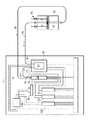
図面の図1および図2を参照すると、本発明の装置は、流体分析装置14に可視光源を提供すると共に、流体分析装置から出射された可視光を検出する光学装置12を収容したハウジング10を備えている。光学装置12および流体分析装置14は共に、データの獲得、スペクトル分析、装置12および14の機能の制御を行うシステム制御装置、好ましくはコンピュータ16に接続されている。
【0022】
光学装置12は好ましくはデュアルビーム分光器18を備えており、このデュアルビーム分光器18は好ましくは標準電源19から電力の供給を受けると共に、400〜700ナノメータ(nm)の可視スペクトルの光を好ましくは10nm単位で受光する2つの入力20と22と、光信号の分散のための回折格子(不図示)と、光ダイオードアレー検出器24(分光器に内蔵)とを備えている。一方の入力20が分析中の流体試料からの光を集める一方、他方の入力22は光源26からの光を直接集光し、基準信号を出すことにより、光源の強度に変動があった場合補正を行えるように構成されている。入力20および22への光の供給は、光源26からシュラウド・シャッタ・アセンブリ(後述)を通り単繊維光ファイバケーブル(single-fiber fiber optic cable)28および30を介して行われる。好ましくは光源26自体をキセノンフラッシュランプ等のハロゲンフラッシュランプで構成し、400〜700ナノメータ(nm)の波長領域の平行光線を出射するようにする。このランプへの電力供給は標準電源31からとするのが好ましい。
【0023】
図2に示すように、光源26は好ましくは可視光を出射する2つの出力32および34を備える。第1出力32は単繊維光ファイバケーブル36を介して流体分析装置14に接続されており、後述するように、試験中の流体試料に対して光を伝播するように構成されている。伝播された光線は流体分析装置14を通過した後、単繊維光ファイバケーブル28を介してデュアルビーム分光器18の入力20に送られてスペクトル分析が行われる。光源の第2出力34は基準チャネルとして作用し、1)測定値をランプ強度のゆらぎに関して較正し、補正する働きと、2)フラッシュランプ26の性能を監視して規格値以下になると直ちに交換できるようにする働きなどを行う。従って出力34は単繊維光ファイバケーブル30を介して、フラッシュランプから直接受光する分光器の入力22に接続されている。
【0024】
前出のシュラウド・シャッタ・アセンブリ38は、出力32から出射された光を遮断することにより光度較正中に暗電流測定を行えるようにするために用いられる。フラッシュランプシュラウド102(図8に示す)内に収容されている1組の光学フィルタ(不図示)を用いてフラッシュランプから出射される光の強度を変えることにより、1)分光計の検出器が高強度の光による飽和や低強度の光による分解能の不足を生じることなく最適な状態で色測定を行えるようにすること、および2)デュアルビーム分光器への光信号をその両側で光度的に均衡させることが可能となる。伝播された光線は流体分析装置14を通過した後、最終的にデュアルビーム分光計18に内蔵されている検出器24(詳細不図示)に導かれる。入力20および22のいずれかからの光が入射スリットを介して分光計に入射すると、まず凹面回折格子に当たり、この回折格子がその固有の波長に光を分散し、光ダイオードアレー検出器に向けて反射する。一方の入力からの光がその後検出器アレーの一方の半分に進むのに対し、他方の入力からの光はアレーのもう一方の半分へと進む。このように分光計内部の回折格子は入射スリットと共に、検出器が単一周波数の光を検出することを可能にし、分光計の波長分解能を定義している。
【0025】
検出器24は、高感度光ダイオードを低雑音増幅器に接続して成る標準光ダイオードアレー検出器とするのが好ましい。透過光がこの検出器に送られてスペクトルの測定が行われ、検出器信号が次に好ましくはRS232ケーブル(不図示)を介してコンピュータ16に送られ、スペクトル分析と、色の測定値となるL*値、a*値およびb*値の計算が行われる。
【0026】
スペクトル分析、被試験流体の色のL*値、a*値およびb*値の計算、および標準との色の比較に使用するカラー技術は公知であり、1983年9月13日発行のファルコフら(Falcoff et al.)による米国特許公報(特許文献2)に十分に記載されており、その内容を本願明細書に援用するものとする。
【0027】
再び図1を参照すると、流体分析装置14は後述の流体制御装置40を備えており、この流体制御装置によって検査対象となる流体または基準流体が流通型流体分析セル42に連続的に供給される。
【0028】
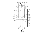
次に図3および図4を参照すると、流体分析セル42は均等な色の流体流を供給することにより、色測定を正確に行えるように構成されている。セル42は2つの半割体44および46を容器の中間で接続してなる円筒形容器を備えている。セルの下側半割体46はその上表面に沿って中央空洞部48を備えている。その空洞部の中に、上側と下側の円形視界窓50と52が相互に間隔をあけて設けられており、空洞部の両端を取り囲むと共に光がセルを通って透過できるようにしている。
【0029】
間隔をあけて設けられた視界窓の間には、流体分析チャンバ54となる空洞部が配置されている。図3に示すように、流体分析チャンバ54は視界窓50と視界窓52の間に真鍮シム材のようなインサートまたはスペーサ部材56を配置して形成されている。スペーサ56は好ましくは楕円形の環状側壁を有しており、この側壁の中に流体流路が形成されている。スペーサ56の厚さはセルの光路長を決めるものであり、任意の大きさとして良いが、実用面での理由(測定対象試料の吸収率)から1〜10ミル(mil)の範囲(0.001〜0.010インチ)の厚さが選択されるのが一般的である。
【0030】
円形弾性の上部ガスケット60と下部ガスケット62も視界窓50および52のそれぞれ上と下に配置されており、流体分析チャンバ54の回りに液密シールを形成している。好ましくはガスケット60および62の各々の中心部に円形ビューイングポート64を設け、光が視界窓を通過できるようにする。
【0031】
上記の各要素をセル下側半割体の中央空洞部に配置した状態で、セルの2つの円筒形半割体44および46を好ましくはボルト(不図示)を十分な力で締結することにより固着して定位置に保持し、好ましくは250psigまでの静水圧力および流体力学的圧力に耐え得る密封されたコンパートメントをセルに対して提供する。
【0032】
セルはまた、流体を流体分析チャンバに流入・流出させる流入チャネル66と流出チャネル68とを備えている。図3に示すように、流入チャネル66と流出チャネル68はセルの上側半割体に沿って形成されており、セル内に縦方向下向きに延在し、さらに上部シール60と上側視界窓50のそれぞれの孔を通って延在して流体分析チャンバ54と流体連通(fluid communication)している。これら2つの流体チャネルは、好ましくはスペーサ部材56の楕円形の孔の2つの中心と整列させることにより、分析チャンバ内に一方向の流れを形成するようにする。好ましくは、ねじ式流体継手70および72をセルの上面で上記流入・流出チャネルにそれぞれねじ込み、該継手に流入管と流出管(不図示)を挿入できるようにする。
【0033】
セルアセンブリを完成するには、セルの下側半割体46と上側半割体44とに中心チャネル74と76をそれぞれ設ける。これらのチャネル74および76はそれぞれの半割体の縦軸全長に沿って延在し、下部および上部視界窓でそれぞれ終端している。これらの中心チャネルの中に、送光用と受光用の光ファイバプローブ78および80がそれぞれ挿入されており、光ファイバプローブ78および80は、流体分析セルに出入りする光に対して経路を提供する光ファイバケーブル36および28にそれぞれ接続されている。プローブは好ましくはサファイヤや石英のような耐久性の高い光学材料で形成された光学的に平坦な窓で終端し、光コリメーションレンズを備えている。これらの窓は、好ましくはシール(不図示)を用いてプローブに固着される。相対する視界窓を備えたプローブ78と80はそれぞれのチャネル内に挿入されて、各ガスケットの中央光学ビューポート64を通って延在するように位置決めされることにより、各プローブの面がセルの窓と連続した同一面となる。プローブ自体が可視光に対して透明の視界窓で終端しているため、プローブの窓または面がセルの窓と連続した同一面となるのである。このため、プローブは流れの方向に対して直角に配置されることになるが、視界窓によって流れからは隔離された状態となる。プローブを軸方向に整列することで、正透過率測定(direct transmission measurement)が可能になる。適正な整列を維持するために、プローブはその軸沿いのさらに後方で止めねじ(不図示)により定位置に保持すると良い。プローブの窓とセルの窓との間に屈折率整合ゲルを用いることによって、結合度をさらに強めることができる。
【0034】
透過セル42の形成に用いられる上述の各構成要素は、装置を通過する流体に対して非反応性の材料で形成する必要がある。一般に、セル半割体、スペーサ、プローブといった構成要素は真鍮、アルミニウム、ハステロイ(hastelloy)またはステンレス鋼で形成され、視界窓とプローブ窓は硼珪酸ガラス、石英またはサファイヤで形成される。視野窓については、フルオロカーボンポリマーで被覆して、セル上に流体が付着するのを防止するようにしても良い。
【0035】
図4に示すように、動作時は、流体が視野窓を通過し視野窓の間を通って流れるのに伴って、流体が広がって概ね層状のフローパターンを描くようになるため、光透過測定は流れの方向に対して垂直に行われることになる。
【0036】
本発明の透過セル42は、上述のように、ゼロバイパスのセル、すなわち流入する全ての流体が視野窓に露出されるセルとして特徴付けることができる。ゼロバイパスによってセル内を流れる試料の流れを均等な剪断力での流れとして一定した界面での測定を可能にすること、および十分な速度の流れとすることでセルの窓に試料が付着するのを防止することが可能となっている。またチャンバは、チャンバ内を通る流れが層状となるように設計されており、これによって流体内に顔料が懸濁している場合でもその顔料の沈降や凝集が防止されると共に、視野領域において均等な色の試料を提供することにより均等な色の測定が保証される。ゼロバイパスセルはまた、全部の流体が光学的ビューパスを横切るようにすることで、真の流体試料が得られることを保証している。
【0037】
本発明で使用するセルのもう一つの特徴は、試料を通る光の光路長が固定されているものの、セル内のシムスペーサ56を交換することにより手作業で設定できる点にある。試料を通る光の光路長の設定は、十分な通過量の光が計器検出器によって正確に測定される程度に小さく、しかも検出器の飽和を回避できる程度に大きくなるように行う。上述のように、光路長は一般に1ミル(mil)から10ミル(mil)の間で設定される。しかし、光学的に高濃度の分散液やチントの中には、完全なスペクトル情報を得るために希釈が必要となるものもある。大量の光散乱体を有する試料については、有意義なスペクトルデータを獲得するために、後述するような拡散透過率または反射率測定値も必要となる場合もある。
【0038】
測定セルとセル内の液体の温度は、好ましくはできるだけ狭い範囲(例えば±5℃)に保持することにより、熱膨張で有効光路長に変化が生じないように、また標準測定値と試料測定値が対比し得るものとなるようにする。本発明における温度制御は、セルに隣接して配置した熱電冷却装置または渦式冷却装置(不図示)を用いて、セルを通過する流体の温度を一定に保つようにするのが好ましい。試験用試料も標準液もこの範囲内の同じ温度で測定し均等性を保証する必要がある。
【0039】
再び図1を参照すると、本発明の装置はさらに流体流制御装置40を含んでいる。制御装置としては一般に、流体を一定の速度で導入口70から装置内へ送り込み、さらにスペーサ56によって形成される流体チャンバ54内へ送り、プローブ78および80の視界窓を横切って流出口72から外へ送り出すものであれば、任意の形式の制御装置を設けることができる。こうすることで、試料体積の流体がセル内を通過する際に窓を通して透過率による色測定を行うことができる。
【0040】
好適な実施形態では、上述のように、分光光度計または検出器18によって点灯されるフラッシュランプ26によって光を発生し、この光を単繊維光ファイバケーブル36を介して試料領域に導入する。単繊維光ファイバケーブル36は、セル42の円筒形本体内で止めねじによってセル窓にしっかりと保持されているプローブ78および80で終端している。
【0041】
液状チントや分散液のような流体を好ましくは加圧下(約60〜80psig)でセル内に強制的に送入するが、これは試料用圧力ポット82を用いて行うのが好ましい。図5に示すように、圧力ポット82自体は、吸気口86と流体試料取出し口88と圧力逃し弁90とを備え、カバーの働きをする蓋部84と、試料を容れる試料ポット92とで構成される。試料中に気泡やフロスが形成されることがないよう、吸気口86はバッフル94により試料から遮断される。試料取出し口88はその下側で浸漬管96に連結されており、浸漬管96は圧力ポットの2つの部分84と92を組み立てた時にポットの底まで延在する。
【0042】
圧力ポットの2つの半割体は、好ましくはテフロン(登録商標)被覆ネオプレンガスケット(不図示)を用い、これを2つの半割体の間に入れて密封する。ガスケットを蓋部84の下にして試料ポット92を配置した後、2つの半割体を合わせて、ブラケット98を用いて密封する。ブラケット98を締結すると、圧力ポットアセンブリの2つの半割体が結合される。このようにして、上部から圧力ポットアセンブリ82に空気が入ると、試料は浸漬管96内を押し上げられ、圧力ポットを出て装置の試料システム内に入り、結果的にセル42へと向かってそこを通過することになる。
【0043】
図1に示す実施形態では、流体制御装置40は空気圧弁または手動弁100および102と、試料のセル内導入用と試料ラインの清掃用として設けられている一つまたは複数の圧力ポット82および83とを備えた試料システムで構成されている。流体制御装置自体は、スペクトル測定値を収集する光学装置の制御を行うのと同じコンピュータ16で制御するのが好ましい。このような制御は、入出力(I/O)ラック(不図示)を通じてRS−232直列リンク(不図示)を用いることで達成することができる。入出力ラックはソレノイド弁(不図示)を作動させて、空気を試料システムの空気圧部品に解放する。好ましくは、さらに別の入出力ラックモジュールを、ポンプ、温度・圧力センサ、およびキャビネット用パージエア源にインターフェースさせる。
【0044】
好ましくは、このシステムは全ての電気・電子部品だけでなく光源も囲い込む防爆型NEMA4筐体10を備えている。この筐体も、エアパージシステム(不図示)で外部環境に関して周囲圧力以上の圧力まで空気をパージすることにより、筐体の外側に存在する恐れのある爆発性の雰囲気が筐体内部に蓄積されるのを防止する。
【0045】
図1に示すように、被試験流体試料は圧力ポット82から、試料か清掃用溶剤を選択することのできる3方弁100、次いでセルを通る流れを清掃のために逆にする4方弁102を介して直接セルに向かう。セルの清掃は、上述のものと全く同じ構成の、清掃用溶剤を容れる第2圧力ポットアセンブリ83により達成することができる。再循環された溶剤は、使用済みの溶剤と試験流体と界面活性剤との混合物を含有しており、これを清掃の困難な状況に使用しても良いし、同じ圧力ポットに試料として導入しても良い。代替的方法として、溶剤および再循環溶剤の貯槽(不図示)に接続したポンプ(不図示)を圧力ポットの代わりに用いて、溶剤と再循環溶剤をそれぞれ清掃目的で流体分析セルに送るようにしても良い。
【0046】
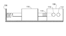
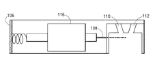
再び図2を参照すると、電子部品筐体10内のフラッシュランプ26は実際のランプにドライバーパックを付したものから成り、円筒形状である。分光光度計18は、試料用1本と基準用1本の計2本のチャネル20および22を有しているため、何らかの方法で2本のファイバ28および30をフラッシュランプ26に連結して、2本の本質的に同じ光チャネルとし、そのうち1本を試料セル42に連結し、他方を分光光度計の基準チャネル22に連結する必要がある。図6および図7に示すように、ここに設けられているフラッシュランプ用シュラウド・シャッタ・アセンブリ38は、長方形ブロック状のシュラウド108を保持するブラケット106を備え、シュラウド108は円筒状の差込用中空部と、ブロックの上部から中空部へと貫通する2つの斜め孔110および112とを備えている。ブラケット106はまたフラッシュランプ26上でキャップとしても作用する。2つの斜め孔はブロック中心から等距離に並置されている。また、これらの孔110および112はブロックの中心縦軸に向かって斜めに形成され、それらの斜線が交わる頂点がランプのフィラメントとなっている。このようにして、ファイバケーブル30と36を、どちらもランプのフィラメントに向けた状態でシュラウド108に連結することができる。
【0047】
分光光度計18のダイオードアレーの熱ドリフトを修正するために、試料測定の前だけでなく分光光度計の光度較正中にも「暗」(“dark”)の読み取りを行う。光度の較正は、通常の場合、透過測定では、清浄な溶剤をセルに注入し、100%透過ラインを測定することによって達成できる。一般的な試料の測定においては、アレーの試料チャネル上の光の強度と基準チャネル上の類似の位置における強度との比を形成することにより、試料チャネル上の光強度をランプ強度のゆらぎに関して補正する。その後、透過率を計算するために、補正結果を較正中に取った100%ラインの比に関する同様の結果で割る。この時点で、ダイオードアレー分光光度計18の基準チャネル22と試料チャネル20とは、実際にはそれぞれ同一の物理的アレーの左側と右側になっている。このため、ほとんどのデュアルビーム分光光度計では、迷光が基準チャネルから試料チャネルへ漏れることから、色の濃い試料の測定を透過モードで行っている場合に問題となりがちなのであるが、チントおよび分散液の測定の場合にこの問題が頻発する。
【0048】
迷光の漏れを補正するために、本発明装置のさらなる特徴として、バネ付きシャッタアセンブリがブラケット106に固定装着されると共に、フラッシュランプのシュラウド108にも取り付けられており、バネ付きシャッタ114がフラッシュランプシュラウドに設けられた試料用光ポート110の正面に介挿できるように構成したことがある。このように構成することで、アレーの基準側が最大限の光強度に曝されている時でも、アレーの試料側でのみ「暗」の読取値を取ることができる。これが実際には基準チャネル22から試料チャネル20へ漏れる迷光の測定値ということになる。試料測定の都度、その前に試料チャネルをブロックした状態でアレー両側の光強度の測定値を取ることで、「照光暗」(“flashing dark”)測定値が形成される。各測定値は試料チャネルと基準チャネル両方の光強度を記録したものであるため、「照光暗」読取値の基準チャネル強度を実際の試料測定における基準チャネルの強度との比で示すことにより、換算係数が得られる。次にこの換算係数を試料側の「照光暗」測定値に適用し、得られた強度を試料側の実際の試料測定値から差し引く。このようにして、ランプの強度のゆらぎに関して補正した迷光の漏れが実際の試料測定値から差し引かれることになる。
【0049】
バネ付きシャッタ114は、交直両用ソレノイド116により平行移動せしめ、交直両用入出力モジュール118(図2に示す)により作動せしめ、標準電源120により電力供給を行い、分光光度計18からの信号によって始動させるようにするのが好ましい。
【0050】
セルから受信した透過データは次に、好ましくはコンピュータ16である制御装置へと自動的に転送され、そこでL*、a*およびb*の比色計算が行われる。スペクトルデータと比色値はその後の使用のために保存され、L*、a*およびb*の基準値はコンピュータスクリーン上でオペレータに報告される。電子部品および光学部品の筐体の内部を試料セルへの光ファイバの結合と共に図2に示している。
【0051】
本発明装置は、結果的に得られた製品の色を測定する様々な化学プロセスに用いることができるが、好ましい用途は、塗料、分散液、インクジェット用インク、あるいはチントの製造プロセスである。本発明の装置は、オンラインまたはオフラインのどちらで試験を行う場合でも製造ラインから遠隔した場所に配置することができ、また製造装置に接続して、製造中の湿潤流体に関してオンラインで色測定を行うようにすることもできる。流体を加工装置から直接セルを通して流すことにより、オンライン試験または連続試験が可能となり、流体のバッチ生産または連続生産を完全に自動化して行うことが可能になる。従来のプロセスでは数時間かかるのに比べて、図1に示す装置のサイクル時間は全部でわずか数分である。さらに、この装置を用いて色測定を行った場合、湿潤流体の色特性とそれに対応する乾燥塗膜の間の相関関係が良くなり、視覚的に正確な色合わせを行うことが可能になるという知見が得られている。
【0052】
本発明の変形例として、分光光度計の代わりに比色計を用いる方法がある。
【0053】
本発明装置の代替的実施形態では、図8に示すように、代替的な流体分析セル200が設けられる。このセルは本質的には上述の図3のものと同じであるが、単繊維光学ファイバの代わりに、同じ長さの4分の1インチ径フェルーレ形コネクタを備えた光学ファイバ束202および204を用いている。光源26から出る光ファイバ束202が、流体分析チャンバ54内の試料に光を照射するのが好ましい。このためには、フラッシュランプのシュラウド108に少し設計変更を加えると共に、デュアルビーム分光光度計18のコネクタを置き換えて前記の形式のコネクタを収容するようにする必要がある。しかし、この実施形態200において最も顕著な特徴は、正反射モードと拡散モードの両方で試料を照射できるように、試料セル内部に積分球206を設けた点にある。このことは、試料が光散乱性の顔料を含んでおり、部分的に透過性、部分的に散乱性である場合に特に重要である。任意の従来型積分球を用いることができる。
【0054】
ここで使用する積分球206は、好ましくは直径1インチで、内側を硫酸バリウムや二酸化チタンなど、反射性の高い白色の材料で被覆したものである。球は4つの入口を有し、そのうち3つは4分の1インチ径の開口、残る1つは2分の1インチ径の開口とするのが好ましい。2分の1インチの開口はセル内部の下側窓52に相対して配置される。積分球はまた、この2分の1インチ開口と4分の1インチの開口の一つに隣接して内部バッフル210を含んでいる。照射用ファイバ束202がこの4分の1インチ開口に連結されて積分球、ひいては試料を照射する。バッフルはファイバ束による試料への直接的または短絡的な照射をブロックする。照射用入口の真向かいにある4分の1インチ開口は、同じ白色反射性材料で被覆した開口プラグ(不図示)で塞がれており、球内部で直射光を反射させる。試料用開口の真向かいにある4分の1インチ開口も白色被覆開口プラグ(不図示)により覆い、光全体(拡散光と正反射光を足したもの)の検出を行うようにしても良いし、あるいは「黒色トラップ」208(頂点が開口部に位置する内部錘状体を備えた円筒形カップで、全体をカーボンブラックのような真黒色の吸収性材料で被覆したもの)で覆い、試料を通る拡散光を測定するようにしても良い。図8に示したのはこの実施形態の試料セルである。
【0055】
本発明装置のさらに別の代替的実施形態は、図9に示すように、試料セルを例外として上述の実施形態200と同じである。この実施形態の試料セル300は、その流体を容れない半割体302に軸方向に延在してファイバ束306へとつながるプローブチャネル304を備える外、軸に対して角度をつけて斜めに延びる1本または複数の補助プローブチャネル308を補助プローブ310と共に備えており、この角度の頂点は円筒体の軸上でセルの2つの窓の間の試料自体の内部に位置している。このようにすることで、セルは試料に対して0度または法線からある角度で照射を行いながら透過セルとして機能することができる。この角度は任意であるが、標準的な45度照射・0度検出に関しては45度とするのが好ましい。ただし、選択肢として、試料に対して斜めに照射し、試料の同じ側で試料に対して直角に検出するようにして、セルを反射モードに変換することも容易に行うことができる。
【0056】
図10に示すさらに別の実施形態では、本発明装置は上述の実施形態200と同様であり、セル400は流体を容れない半割体402に積分球402を内蔵し、積分球を用いて透過測定を行う設計となっている。実施形態200と同様に、球404の2分の1インチ開口がセルの下側窓52に臨んで配置されると共に、この2分の1インチ開口の反対側に4分の1インチ開口を備え、白色リフレクタ(不図示)または黒色トラップ406がここに内蔵される。光源から延在するファイバ束408が上述のように球の照明に用いられる。しかし、本実施形態では、流体を容れる方の半割体410に、その軸に沿って延在してファイバ束414に達するプローブチャネル412も備えるが、さらに軸に対して角度をつけて延びる1本または複数の補助プローブチャネル416を補助プローブ418と共に備えている。この角度の頂点は円筒体の軸上でセルの2つの窓の間の試料自体の内部に位置している。このようにして円筒体の軸に対して斜めに延在する補助プローブ418を用い、プローブ414で試料に対して直角に検出することによって反射率測定を行うことができる。先の場合と同様に、その角度は任意である。また他の使用器具は上記の場合と同じである。
【0057】
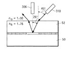
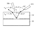
本発明装置のさらに別の実施形態では、上述の実施形態300のセルと同じであるが反射モードを用いる代替的流体分析セルが設けられる。空気の界面が光ファイバ束310と光学窓52(サファイヤ、石英、BK7、硼珪酸塩、石英ガラス等から成る)との間にあるため、窓の後方にある試料の照射角度(窓への法線に関する角度)は円筒体軸に対するプローブの角度と必ずしも同じにする必要はない。これは窓の材料の屈折率によるものである。例えばサファイヤが窓の材料である場合、その屈折率が1.76であるため、湿潤試料に光が衝突する実際の角度(窓材料内部での)はスネルの法則、すなわちnasinθa=nssinθsを用いて計算しなければならず、窓の第1面上で推測される角度(空気中)とはかけ離れたものとなる。この状態を示したのが図11である。
【0058】
この屈折率効果を補正し、窓の表面に関して(すなわち空気と窓の界面に関して)斜位を有する光学プローブを維持するための一つの手段として、照射と検出のジオメトリーを調整して、窓の材料内部で真に45度の照射・検出角度が得られるようにすることがある。再びスネルの法則を用いて、この条件を達成するために必要な空気中の照射角度と検出角度を算出することができる。これについて、サファイヤ製の窓に関する一例を示したのが図12である。この場合、照射用光ファイバ束310が円筒体軸に関して60度傾いているのに対し、検出用光ファイバ束306は円筒体軸から照射用ファイバ束と反対側に該軸に関して15.5度傾いており、これによってサファイヤ製窓の内部で45度のオフセットが達成されている。
【0059】
そこで、反射モードにおける標準比色測定の場合のように、45/0の照射・検出ジオメトリーを達成する図12の概念を用いた本実施形態の湿潤セル500の構成を図13に示す。ここでも光ファイバ束を光学プローブとして利用し、プローブの角度は図12の通りとしている。従って実施形態500は、実施形態300と同じであるが、例外としてセル500はその流体を容れない半割体502に検出ファイバ束506用のプローブチャネル504を円筒体軸に対して角度をつけて設けると共に、円筒体軸に対して検出プローブ反対側にやはり軸に対して角度を付けた1本または複数の補助プローブチャネル508を補助プローブ510と共に設けている。このとき角度の頂点は円筒体の軸上でセルの2つの窓の間の試料内部に位置している。プローブの角度は窓の材料に応じて変化する。
【0060】
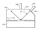
ただし、45/0ジオメトリーをセルの構成に組み込む方法はこれだけではない。実際には空気と窓の界面における屈折率効果を無くすことが望ましい。このためには、ファイバ束プローブを窓の材料に連結する際、その表面に対して直角に連結することが必要である。従って試料表面に対する照射方向または検出方向を直角以外の角度にするためには、プローブが窓に接触する側で、窓が試料に対して適切な角度を取ることが必要である。換言すると、窓に適切な角度の1つまたはそれ以上のファセットを組み込むことにより、両方の条件を満たすことができる。45/0ジオメトリーの場合、光学ファイバ束プローブと接触する窓は図14の構成をとることになる。この実施形態の湿潤セル600の構成を図15に示す。ここでも光ファイバ束を光学プローブとして利用しており、プローブと窓の配置については図14と同様である。この場合、照射用光ファイバ束610は円筒体軸に対して45度傾斜しているが、窓612の表面への法線に関する傾斜角度は0度である。これに対し、検出用光ファイバ束606は円筒体軸に平行であり、従って窓内部で真の45/0ジオメトリーを達成している。
【0061】
またこの特定の場合では、窓の材料として石英など屈折率1.51の材料が示されているが、任意の材料で良い。ただし、内部全反射のような屈折率の効果を小さくすると共に、外部散乱効果を減少させるためにも、窓の屈折率と試験中の試料の屈折率をできるだけ一致させるのが望ましい。従って、実施形態600は実施形態300と同様に、流体を容れない方の半割体602に、その軸に沿って延在するプローブチャネル604を検出ファイバ束606用として備えると共に、軸に対して角度をつけて延在する1本または複数本の補助プローブチャネル608を補助プローブ610と共に備えている。このとき角度の頂点は円筒体の軸上でセルの2つの窓の間の試料自体の内部に位置している。本実施形態と実施形態300との主な相違点は、試料に対してプローブ界面を提供する窓612が1つまたはそれ以上のファセット614を光学ファイバ束またはプローブと界面接続させる端部に切り込んだ円筒形であり、ファイバ束が常に窓の表面に対して直角になるように構成されている点である。
【0062】
上記の設計をさらに発展させたものとして、より厚くした窓に複数のファセットを設け、その試料表面に対する角度を、ASTMで定義されるところの平面角、高角および近反射角に複数の検出プローブを配置できるような角度とすることにより、金属フレーク、パール(pearl)フレーク等の干渉物質を含む塗料、チント、あるいは分散液の測定を行えるようにしたものがある。
【図面の簡単な説明】
【0063】
【図1】本発明の装置を示す略図である。
【図2】図1の装置の光学装置と流体分析セルのみを示す部分正面図である。
【図3】図1の装置に用いられている流体分析セルの正面図である。
【図4】図3の流体分析セルを通る流体を示す流体分析セルの部分図である。
【図5】図1の装置に用いられている圧力ポットアセンブリの正面図である。
【図6】図1の装置に用いられているフラッシュランプ用出力を含むフラッシュランプのシュラウド・シャッタ・アセンブリを示す正面図である。
【図7】図6の装置の側面図である。
【図8】本発明による別の流体分析セルを示す正面図である。
【図9】本発明によるさらに別の流体分析セルを示す正面図である。
【図10】本発明によるさらに別の流体分析セルを示す正面図である。
【図11】、屈折率の不一致の補正のためにセルに施す必要のある調整について説明する流体分析セル窓部の略図である。
【図12】屈折率の不一致の補正のためにセルに施す必要のある調整について説明するさらに別の流体分析セル窓部の略正面図である。
【図13】図11および図12の補正要素を考慮に入れた、本発明によるさらに別の流体分析セルを示す正面図である。
【図14】屈折率の不一致の補正のための調整をセルに施す必要を無くした流体分析セル窓部の略図である。
【図15】図14の上記補正要素を考慮に入れた本発明によるさらに別の装置を示す正面図である。【Technical field】
[0001]
The present invention relates to a fluid testing method and device. The invention particularly relates to an improved device for measuring, by transmission and / or reflection, the color properties of fluids such as paint dispersions and tints flowing in the device.
[Background Art]
[0002]
Today, pigment dispersions and tints are widely used in formulating high performance coating compositions, particularly for exterior finishes for automobiles and trucks.
[0003]
One problem in the production of such dispersions and tints is that by measuring the color and intensity of the material in the process of being manufactured, the color tolerance of the material may be within an acceptable range. There is a need to be able to adjust quickly. Currently, color measurements are made manually, taking an aliquot of the material, mixing it with a standard white paint or a standard black paint, spraying this mixture as a coating on the panel, and firing and drying the panel. Thereafter, one or more color properties of the dried coating are measured using a colorimeter or spectrophotometer, against a standard. Thereafter, adjustments are made to the batch until it matches the standard color parameters.
[0004]
The color measurement by this method is very time-consuming because there is time for sample preparation and drying. Also, this procedure must be repeated many times to achieve the desired color characteristics. A further problem with this method is that the accuracy of the test depends on the stability of the color and strength of the standard white or black paint. Even with careful care, these standard paints tend to change from batch to batch and also to agglomerate or settle over time, resulting in poor reproducibility of the test and the process of manufacture. It is very difficult to accurately analyze the color and intensity of the batch.
[0005]
It has long been a goal in the industry to measure the color properties of these fluids in an undried state, and to be able to measure the color of the fluid when applied and dried in a predictable manner. The main advantage gained by this is time savings, but is also associated with a higher potential for automated manufacturing processes.
[0006]
Regarding the measurement by transmission, a conventional laboratory spectrophotometer using a cuvette-type sample chamber has been proposed. By measuring the transmission spectrum of a transparent sample in a wet state, it can be measured off-line in the wet state as described above. Perform the measurement. However, in such a spectrophotometer, the optical density of the fluid generally tends to be too high, so that the cell optical path length is too long to perform such a measurement. It is also conceivable that the color of the sample changes when sedimentation or aggregation occurs. In addition, simply taking a wet sample, placing it in a glass cell, and measuring its color properties often results in inconsistent tests, often due to poor reproducibility and operator variability. Often results.
[0007]
Regarding the measurement in reflection mode, some would suggest using a conventional colorimeter to measure the free surface of an undried coating of a fluid such as a pigment dispersion or tint. Such coatings will also have erroneous results and unacceptable measurement variations due to problems with uneven surfaces, sedimentation, agglomeration, and lack of hiding. In addition, combining such a device with a wet sample has its own set of problems, including operating the device where volatile and flammable solvents are released from the sample surface. It can be said.
[0008]
The device described in U.S. Pat. No. 6,026,097 to Batista et al. Uses a variable optical path fluid measurement cell to measure fluid properties, including color, as described above. Could be used for various measurements. However, this device has a large number of movable parts that form a part of a fluid passage, which may cause difficulty in cleaning and maintenance. Another drawback is that the design requires a large amount of fluid sample in order to obtain proper measurement values.
[0009]
Therefore, results with acceptable consistency are obtained, spraying and mixing with a white or black standard, no need to make many dry samples, and cleaning in a short time (1 to 1). (2 minutes or less), the measurement cycle time is extremely short compared to the process change, the means for sending the sample to the analysis cell (automatic means, etc.) is easy, and the measurement of the fluid relating to color and intensity can be performed at high speed. There is still a need for a method and apparatus for color measurement of liquid fluids, characterized by the ability to reliably predict that wet measurements will also meet dry standards.
[0010]
In addition to the above features, there is also a need for an apparatus and method that is inherently a safe configuration and that can be installed on a factory floor in an environment that can create an explosive atmosphere.
[0011]
In addition, the color and intensity properties of these types of fluids can be fully characterized off-line (eg, in controlled laboratories or color development facilities) to provide a more versatile instrument. There are needs.
[0012]
[Patent Document 1]
[Patent Document 2]
U.S. Pat. No. 4,403,866
DISCLOSURE OF THE INVENTION
[Means for Solving the Problems]
[0013]
The fluid testing device of the present invention
A fluid analysis cell having a cavity therein,
Upper and lower light transmission windows surrounding both ends of the cavity,
A spacer having an annular side wall fixedly disposed between the upper and lower viewing windows in the cavity, forming a fluid chamber through which fluid flows between the windows;
The fluid is connected to the fluid chamber in fluid communication, and preferably directs fluid to the fluid chamber such that fluid flow through the chamber is unidirectional laminar with equal shear forces. Fluid inflow and outflow channels for inflow and outflow;
An optional pressure vessel containing a fluid sample therein and delivering the sample to the fluid analysis cell by pressurization;
An optional second pressure vessel for containing a cleaning solvent, sending the solvent to the fluid analysis cell by pressurization, and causing the cell and fluid sample line to be cleaned,
A light transmitting probe and a light receiving probe which are arranged in an arbitrary order above and below the upper and lower viewing windows, wherein the surfaces of the respective probes are axially aligned with each other, and are continuous with the viewing window. Being on the same plane and perpendicular to the flow direction, but separated from the flow by a viewing window, allows transmission measurements to be taken at right angles to the flow direction. Configured light transmitting probe and light receiving probe,
Each is connected to the probe so as to perform irradiation of light to the fluid analysis cell and detection of light from the fluid analysis cell, and to measure a color parameter of a fluid passing through the view window by transmittance. It comprises a light source and a spectrophotometer, each being configured, preferably a flashlamp and a dual beam spectrophotometer, respectively.
[0014]
In another embodiment, a fiber optic bundle may be used instead of the light transmitting probe.
[0015]
In yet another embodiment, a light transmitting probe or fiber optic bundle is interfaced with one of the viewing windows of the fluid analysis cell to allow for diffuse or specular transmittance measurements on the fluid sample to be analyzed. be able to.
[0016]
In yet another embodiment, a further probe may be positioned at an angle to the normal to the fluid sample to enable reflectance measurements to be performed on the fluid sample to be analyzed.
[0017]
In yet another embodiment, instead of one of the viewing windows of the fluid analysis cell, a cylinder made of the same material as the analysis cell window that is transparent to visible light is provided, and a surface of the fluid sample is provided on the surface of the fluid sample. One or more facets at an angle other than parallel to the surface of the cylinder of the cylinder farther from the surface of the fluid sample and parallel to the surface of the fluid sample to form one or more facets. By interfacing with a plurality of additionally provided optical probes, it is also possible to carry out reflectance measurements on the fluid sample to be analyzed.
[0018]
The inspection device of the present invention preferably further comprises
A purged explosion-proof enclosure containing all electrical and electronic components as well as the instrument light source;
An automatic pneumatically controlled sample system for sending the sample to the fluid analysis cell.
[0019]
A method for measuring the color characteristics of a fluid using the above-described apparatus also forms part of the present invention.
BEST MODE FOR CARRYING OUT THE INVENTION
[0020]
In general, the devices of the present invention can be used to test a wide variety of fluids, but are specifically designed to measure the color characteristics of dispersions and tints used in the manufacture of high performance automotive coatings. It is. Specifically, the device of the present invention measures the color characteristics of the fluid flowing through the device using wetted light transmission and / or reflectance measurements throughout the visible spectrum to provide an accurate instrument. It is designed to obtain measured values.
[0021]
Referring to FIGS. 1 and 2 of the drawings, the apparatus of the present invention provides a
[0022]
The
[0023]
As shown in FIG. 2,
[0024]
The aforementioned
[0025]
[0026]
Spectral analysis, L of fluid under test * Value, a * Value and b * The color techniques used to calculate values and compare colors to standards are well known and are fully described in US Patent Publication No. US Pat. And the contents thereof are incorporated herein by reference.
[0027]
Referring again to FIG. 1, the
[0028]
Referring next to FIGS. 3 and 4, the
[0029]
A cavity serving as the
[0030]
Circular elastic
[0031]
With each of the above elements positioned in the central cavity of the lower half of the cell, the two
[0032]
The cell also includes an
[0033]
To complete the cell assembly, the
[0034]
Each of the above components used to form the
[0035]
As shown in FIG. 4, during operation, as the fluid passes through the viewing windows and flows between the viewing windows, the fluid spreads and draws a generally laminar flow pattern, so that light transmission measurement is performed. Will be performed perpendicular to the direction of flow.
[0036]
The
[0037]
Another feature of the cell used in the present invention is that although the optical path length of light passing through the sample is fixed, it can be set manually by exchanging the
[0038]
The temperature of the measuring cell and the liquid in the cell are preferably kept as narrow as possible (eg ± 5 ° C.) so that the effective optical path length does not change due to thermal expansion, and the standard and sample measurements are taken. Is to be comparable. The temperature control in the present invention is preferably performed by using a thermoelectric cooling device or a vortex cooling device (not shown) arranged adjacent to the cell so as to keep the temperature of the fluid passing through the cell constant. Both the test sample and the standard solution need to be measured at the same temperature within this range to ensure uniformity.
[0039]
Referring again to FIG. 1, the device of the present invention further includes a fluid
[0040]
In the preferred embodiment, as described above, light is generated by a
[0041]
A fluid, such as a liquid tint or dispersion, is forcibly pumped into the cell, preferably under pressure (about 60-80 psig), preferably using a
[0042]
The two halves of the pressure pot are preferably sealed using a Teflon coated neoprene gasket (not shown) which is placed between the two halves. After placing the
[0043]
In the embodiment shown in FIG. 1, the
[0044]
Preferably, the system comprises an explosion-
[0045]
As shown in FIG. 1, a fluid sample under test is supplied from a
[0046]
Referring to FIG. 2 again, the
[0047]
In order to correct for the thermal drift of the diode array of the
[0048]
In order to compensate for stray light leakage, a further feature of the apparatus of the present invention is that a spring-loaded shutter assembly is fixedly mounted to the
[0049]
The spring-loaded
[0050]
The transmitted data received from the cell is then automatically transferred to a controller, preferably a
[0051]
Although the device of the present invention can be used in various chemical processes to measure the color of the resulting product, the preferred application is in the production of paints, dispersions, inkjet inks, or tints. The device of the present invention can be located remotely from the production line whether testing online or offline, and can be connected to the production equipment to perform online color measurements on the wet fluid being produced. You can also do so. Flowing the fluid directly from the processing equipment through the cell allows for on-line or continuous testing, and allows for fully automated batch or continuous production of fluids. The cycle time of the apparatus shown in FIG. 1 is only a few minutes in total, compared to several hours in a conventional process. Furthermore, when color measurement is performed using this apparatus, the correlation between the color characteristics of the wetting fluid and the corresponding dry coating is improved, and visually accurate color matching can be performed. Knowledge has been obtained.
[0052]
As a modification of the present invention, there is a method using a colorimeter instead of the spectrophotometer.
[0053]
In an alternative embodiment of the device of the present invention, an alternative
[0054]
The integrating
[0055]
Yet another alternative embodiment of the device of the invention is the same as
[0056]
In still another embodiment shown in FIG. 10, the device of the present invention is similar to the above-described
[0057]
In yet another embodiment of the device of the present invention, an alternative fluid analysis cell is provided that is the same as the cell of
[0058]
One way to correct this refractive index effect and maintain the optical probe with an oblique with respect to the surface of the window (ie, with respect to the air-window interface) is to adjust the illumination and detection geometry to adjust the window material. In some cases, a true 45 degree irradiation / detection angle may be obtained inside. Again, using Snell's law, the irradiation angle in air and the detection angle required to achieve this condition can be calculated. FIG. 12 shows an example of a window made of sapphire. In this case, the irradiation
[0059]
FIG. 13 shows a configuration of the wet cell 500 according to the present embodiment using the concept of FIG. 12 that achieves the 45/0 irradiation / detection geometry as in the case of the standard colorimetric measurement in the reflection mode. Here, the optical fiber bundle is used as an optical probe, and the angle of the probe is as shown in FIG. Thus, embodiment 500 is the same as
[0060]
However, this is not the only way to incorporate the 45/0 geometry into the cell configuration. In practice, it is desirable to eliminate the refractive index effect at the interface between air and the window. For this purpose, it is necessary to connect the fiber bundle probe to the window material at right angles to the surface thereof. Therefore, in order to set the irradiation direction or the detection direction to the sample surface at an angle other than a right angle, it is necessary that the window has an appropriate angle with respect to the sample on the side where the probe contacts the window. In other words, both conditions can be met by incorporating one or more facets at appropriate angles into the window. In the case of the 45/0 geometry, the window that contacts the fiber optic bundle probe will have the configuration of FIG. FIG. 15 shows the configuration of the
[0061]
In this specific case, a material having a refractive index of 1.51 such as quartz is shown as a material of the window, but any material may be used. However, in order to reduce the effect of the refractive index such as total internal reflection and to reduce the external scattering effect, it is desirable that the refractive index of the window and the refractive index of the sample under test match as much as possible. Thus,
[0062]
As a further development of the above design, a thicker window is provided with a plurality of facets, and its angle to the sample surface is set to several planes, high angles and near reflection angles as defined by ASTM. Some angles are set so that they can be arranged so that paints, tints, or dispersions containing interference substances such as metal flakes and pearl flakes can be measured.
[Brief description of the drawings]
[0063]
FIG. 1 is a schematic diagram showing the device of the present invention.
FIG. 2 is a partial front view showing only an optical device and a fluid analysis cell of the device of FIG. 1.
FIG. 3 is a front view of a fluid analysis cell used in the apparatus of FIG.
FIG. 4 is a partial view of a fluid analysis cell showing the fluid passing through the fluid analysis cell of FIG. 3;
FIG. 5 is a front view of a pressure pot assembly used in the apparatus of FIG.
6 is a front view of a flash lamp shroud shutter assembly including a flash lamp output used in the apparatus of FIG. 1;
FIG. 7 is a side view of the device of FIG. 6;
FIG. 8 is a front view showing another fluid analysis cell according to the present invention.
FIG. 9 is a front view showing still another fluid analysis cell according to the present invention.
FIG. 10 is a front view showing still another fluid analysis cell according to the present invention.
FIG. 11 is a schematic diagram of a fluid analysis cell window illustrating adjustments that need to be made to the cell to correct for refractive index mismatch.
FIG. 12 is a schematic front view of yet another fluid analysis cell window illustrating adjustments that need to be made to the cell to correct for refractive index mismatch.
FIG. 13 is a front view of yet another fluid analysis cell according to the present invention, taking into account the correction elements of FIGS. 11 and 12.
FIG. 14 is a schematic diagram of a fluid analysis cell window that eliminates the need to make adjustments to the cell to correct for refractive index mismatch.
FIG. 15 is a front view of a further alternative device according to the present invention, taking into account the correction element of FIG. 14;
Claims (20)
内部に空洞部を有する流体分析セルと、
前記空洞部の両端を囲む上側および下側の光透過窓と、
前記空洞部内の前記上側視界窓と下側視界窓との間に固定配置されて、前記窓の間を流体が通る流体チャンバを形成するスペーサと、
前記流体チャンバと流体連通(fluid communication)するように接続されて、流体が前記流体チャンバに対して流入および流出できるようにする流体流入・流出チャネルと、
上記上側および下側の視界窓の上方および下方に任意の順序で配置される送光プローブおよび受光プローブであって、各プローブの面が相互に軸方向に整列されており、かつ視界窓と連続的な同一面上にあり、流れの方向とは直角を成すが流れからは視界窓によって離隔されていることによって、流れの方向に対して直角に透過率測定を行うことができるように構成されている送光プローブと受光プローブとを備えていることを特徴とする装置。A fluid testing device,
A fluid analysis cell having a cavity therein,
Upper and lower light transmission windows surrounding both ends of the cavity,
A spacer fixedly disposed between the upper and lower viewing windows in the cavity to form a fluid chamber through which fluid passes between the windows;
Fluid inflow and outflow channels connected in fluid communication with the fluid chamber to allow fluid to flow into and out of the fluid chamber;
A light transmitting probe and a light receiving probe which are arranged in an arbitrary order above and below the upper and lower viewing windows, wherein the surfaces of the respective probes are axially aligned with each other, and are continuous with the viewing window. It is configured to be able to perform transmittance measurement perpendicular to the flow direction by being on the same plane and perpendicular to the flow direction but separated from the flow by the view window. A light transmitting probe and a light receiving probe.
全ての電気・電子部品と計器用の光源とを収容するパージ式防爆筐体と、
前記試料を流体分析チャンバに送る自動空気圧制御式試料システムと、をさらに備えていることを特徴とする請求項2に記載の装置。A pressure vessel containing a fluid sample and sending the sample to the fluid analysis cell by pressurization,
A purged explosion-proof enclosure that houses all electrical and electronic components and the light source for the instrument;
The apparatus of claim 2, further comprising: an automatic pneumatically controlled sample system that sends the sample to a fluid analysis chamber.
前記試料の測定前毎に、「照光暗」(“flashing dark”)の読取値の取得が可能となるように、前記分光光度計の検出器アレーの試料側を、基準側から漏れる迷光を除いては暗の状態とする一方、当該アレーの基準側は全強度の光に曝露されながら、フラッシュランプのシュラウドに設けられた試料用光ポート正面にシャッタを介挿ことにより試料チャネルを閉鎖した状態で分光光度計の両チャネルの光強度を測定し、
前記「照光暗」の読取値の基準チャネル強度と、実際の試料測定値における基準チャネルの強度との比を取って換算係数を求め、
「照光暗」の試料チャネル強度に前記換算係数を適用し、
その結果得られた比率化した「照光暗」試料チャネル強度を実際の試料測定値の試料側から引くことにより、ランプ強度のゆらぎに関して補正した迷光の漏れを実際の試料測定値から引くことによって、デュアルビーム分光光度計の基準チャネルから流体試料チャネルへの迷光の漏れを補正する方法。A method of correcting stray light leakage from a reference channel of a dual beam spectrophotometer to a fluid sample channel,
Each time before the measurement of the sample, the sample side of the detector array of the spectrophotometer is removed so that stray light leaking from the reference side can be obtained so that a reading value of “flashing dark” can be obtained. While the reference side of the array is exposed to full-intensity light while the sample channel is closed by inserting a shutter in front of the sample light port provided on the flash lamp shroud. Measure the light intensity of both channels of the spectrophotometer with
The conversion coefficient is obtained by taking the ratio of the reference channel intensity of the reading value of the `` illumination dark '' and the reference channel intensity in the actual sample measurement value,
Applying the conversion factor to the sample channel intensity of "illumination dark",
By subtracting the resulting proportional "illumination dark" sample channel intensity from the sample side of the actual sample measurement, and subtracting the stray light leakage corrected for lamp intensity fluctuations from the actual sample measurement, A method of correcting stray light leakage from a reference channel of a dual beam spectrophotometer to a fluid sample channel.
Applications Claiming Priority (2)
| Application Number | Priority Date | Filing Date | Title |
|---|---|---|---|
| US27696701P | 2001-03-19 | 2001-03-19 | |
| PCT/US2002/008447 WO2002075285A2 (en) | 2001-03-19 | 2002-03-19 | Method and apparatus for measuring the color properties of fluids |
Publications (2)
| Publication Number | Publication Date |
|---|---|
| JP2004527744A true JP2004527744A (en) | 2004-09-09 |
| JP2004527744A5 JP2004527744A5 (en) | 2005-12-22 |
Family
ID=23058860
Family Applications (1)
| Application Number | Title | Priority Date | Filing Date |
|---|---|---|---|
| JP2002573652A Withdrawn JP2004527744A (en) | 2001-03-19 | 2002-03-19 | Method and apparatus for measuring color characteristics of fluid |
Country Status (9)
| Country | Link |
|---|---|
| US (2) | US6888636B2 (en) |
| EP (1) | EP1370849B1 (en) |
| JP (1) | JP2004527744A (en) |
| KR (1) | KR20030087020A (en) |
| BR (1) | BR0208618A (en) |
| CA (1) | CA2438291A1 (en) |
| DE (1) | DE60222864T2 (en) |
| MX (1) | MXPA03008400A (en) |
| WO (1) | WO2002075285A2 (en) |
Cited By (7)
| Publication number | Priority date | Publication date | Assignee | Title |
|---|---|---|---|---|
| JP2007515648A (en) * | 2003-12-22 | 2007-06-14 | ビーエーエスエフ コーティングス アクチェンゲゼルシャフト | Flow-oriented high-precision multi-angle reflectivity sensor |
| JP2008525817A (en) * | 2004-12-28 | 2008-07-17 | システック、エルエルシー | Fluid analyzer |
| JP2009527769A (en) * | 2006-02-22 | 2009-07-30 | アキュリ インスツルメンツ インク. | Optical system for flow cytometer |
| WO2011108293A1 (en) * | 2010-03-03 | 2011-09-09 | 株式会社日立ハイテクノロジーズ | Hard disk media inspection device and inspection method |
| JP2016038321A (en) * | 2014-08-08 | 2016-03-22 | 国立大学法人九州大学 | Optical analysis system, sensor apparatus, and optical analysis method |
| KR20210062685A (en) * | 2018-09-24 | 2021-05-31 | 에이치에프 사이언티픽, 엘엘씨. | SPECTROPHOTOMETER FOR USE IN EXPLOSIVE ATMOSPHERES |
| JP7388801B2 (en) | 2018-11-08 | 2023-11-29 | ロジェリオ バプティスタ アウアド | Fluid analysis device and method |
Families Citing this family (42)
| Publication number | Priority date | Publication date | Assignee | Title |
|---|---|---|---|---|
| US7027147B2 (en) * | 2001-03-19 | 2006-04-11 | E. I. Dupont De Nemours And Company | Method and apparatus for measuring the color properties of fluids |
| DE10330641A1 (en) * | 2003-07-07 | 2005-02-03 | Basf Coatings Ag | High-precision remission sensor for wet measurement of paints and pigment pastes |
| BRPI0418865A (en) * | 2004-05-25 | 2007-11-20 | Renner Herrmann Sa | apparatus and method for measuring the spectral properties of a fluid |
| US7999929B2 (en) * | 2004-08-02 | 2011-08-16 | The Furukawa Electric Co., Ltd. | Specimen optical information recognizing device and its recognizing method |
| DE102005003372B4 (en) * | 2005-01-24 | 2024-04-18 | Gunther Krieg | Method and device for controlling the concentration of components of additives in a pressure process fluid |
| KR100651031B1 (en) * | 2005-07-08 | 2006-11-29 | 장민준 | Integrating sphere having means for temperature control |
| US7996188B2 (en) | 2005-08-22 | 2011-08-09 | Accuri Cytometers, Inc. | User interface for a flow cytometer system |
| US8017402B2 (en) | 2006-03-08 | 2011-09-13 | Accuri Cytometers, Inc. | Fluidic system for a flow cytometer |
| US8303894B2 (en) | 2005-10-13 | 2012-11-06 | Accuri Cytometers, Inc. | Detection and fluidic system of a flow cytometer |
| BRPI0620580A2 (en) | 2005-12-05 | 2011-11-16 | Du Pont | probe for liquid property measurement |
| US7542143B2 (en) * | 2005-12-05 | 2009-06-02 | E.I. Du Pont De Nemours And Company | Liquid measurement cell having a pressurized air cavity therein |
| US7719686B2 (en) * | 2005-12-05 | 2010-05-18 | E.I. Du Pont De Nemours And Company | System for measuring a color property of a liquid |
| US7477394B2 (en) * | 2005-12-05 | 2009-01-13 | E.I Du Pont De Nemours & Company | Method for measuring a color property of a liquid using a liquid measurement cell having a transparent partition therein |
| US7423755B2 (en) * | 2005-12-05 | 2008-09-09 | E.I. Du Pont De Nemours And Company | Liquid measurement cell having a transparent partition therein |
| US8149402B2 (en) * | 2006-02-22 | 2012-04-03 | Accuri Cytometers, Inc. | Optical system for a flow cytometer |
| US8031340B2 (en) * | 2006-02-22 | 2011-10-04 | Accuri Cytometers, Inc. | Optical system for a flow cytometer |
| US8283177B2 (en) | 2006-03-08 | 2012-10-09 | Accuri Cytometers, Inc. | Fluidic system with washing capabilities for a flow cytometer |
| US7780916B2 (en) | 2006-03-08 | 2010-08-24 | Accuri Cytometers, Inc. | Flow cytometer system with unclogging feature |
| US8362436B1 (en) | 2006-03-14 | 2013-01-29 | Advanced Precision Inc. | Electro-optic fluid quantity measurement system |
| US7573565B1 (en) * | 2006-03-14 | 2009-08-11 | Strube, Inc. | Methods and systems for determining the density and/or temperature of fluids |
| US8715573B2 (en) | 2006-10-13 | 2014-05-06 | Accuri Cytometers, Inc. | Fluidic system for a flow cytometer with temporal processing |
| US8445286B2 (en) * | 2006-11-07 | 2013-05-21 | Accuri Cytometers, Inc. | Flow cell for a flow cytometer system |
| US7739060B2 (en) * | 2006-12-22 | 2010-06-15 | Accuri Cytometers, Inc. | Detection system and user interface for a flow cytometer system |
| US8432541B2 (en) | 2007-12-17 | 2013-04-30 | Accuri Cytometers, Inc. | Optical system for a flow cytometer with an interrogation zone |
| US7843561B2 (en) | 2007-12-17 | 2010-11-30 | Accuri Cytometers, Inc. | Optical system for a flow cytometer with an interrogation zone |
| US8733949B2 (en) * | 2007-12-24 | 2014-05-27 | Columbia Insurance Company | System for representing colors including an integrating light capsule |
| US8507279B2 (en) | 2009-06-02 | 2013-08-13 | Accuri Cytometers, Inc. | System and method of verification of a prepared sample for a flow cytometer |
| DE102009037240A1 (en) * | 2009-08-12 | 2011-02-17 | Siemens Aktiengesellschaft | Method and device for determining chemical and / or physical properties of operating materials in a machine installation |
| WO2011106402A1 (en) | 2010-02-23 | 2011-09-01 | Accuri Cytometers, Inc. | Method and system for detecting fluorochromes in a flow cytometer |
| US9551600B2 (en) | 2010-06-14 | 2017-01-24 | Accuri Cytometers, Inc. | System and method for creating a flow cytometer network |
| EP2633284B1 (en) | 2010-10-25 | 2021-08-25 | Accuri Cytometers, Inc. | Systems and user interface for collecting a data set in a flow cytometer |
| US8528385B2 (en) | 2010-12-30 | 2013-09-10 | Eaton Corporation | Leak detection system |
| US9291521B2 (en) | 2010-12-30 | 2016-03-22 | Eaton Corporation | Leak detection system |
| GB2496897A (en) * | 2011-11-25 | 2013-05-29 | Colvistec Ag | Measurement of colour strength of a diffusely reflective liquid e.g. paint |
| JP6481021B2 (en) * | 2015-03-24 | 2019-03-13 | 大塚電子株式会社 | Reference light source device used for calibration of spectral luminance meter and calibration method using the same |
| AT519912B1 (en) * | 2017-05-03 | 2019-11-15 | Avl List Gmbh | Condensation particle counter with separating element |
| AT519913B1 (en) * | 2017-05-03 | 2019-11-15 | Avl List Gmbh | Condensation particle counter with light guide |
| WO2018213596A1 (en) | 2017-05-17 | 2018-11-22 | Spogen Biotech Inc. | Devices, systems, and methods for agrochemical detection and agrochemical compositions |
| JP7068343B2 (en) | 2017-05-19 | 2022-05-16 | ビーエーエスエフ コーティングス ゲゼルシャフト ミット ベシュレンクテル ハフツング | Formulation module production system |
| US20200386670A1 (en) * | 2018-01-04 | 2020-12-10 | Chr. Hansen Natural Colors A/S | Color measurements of turbid liquids |
| US10634466B2 (en) * | 2018-02-01 | 2020-04-28 | The United States Of America, As Represented By The Secretary Of The Navy | Sealable short-pathlength liquid transmission cell for fourier-transform infrared spectroscopy applications |
| DE102018107322A1 (en) * | 2018-03-27 | 2019-10-02 | MAX-PLANCK-Gesellschaft zur Förderung der Wissenschaften e.V. | Measuring cell and measuring device |
Family Cites Families (40)
| Publication number | Priority date | Publication date | Assignee | Title |
|---|---|---|---|---|
| DE240075C (en) | ||||
| US628878A (en) * | 1898-06-16 | 1899-07-11 | Pierre C Waring | Hat-making machine. |
| GB884863A (en) | 1958-09-15 | 1961-12-20 | S L F Engineering Company | Expansible volume analyzer sample cell for colorimetric analyzer |
| US3571589A (en) * | 1969-06-04 | 1971-03-23 | Barringer Research Ltd | Method for absorption analysis using a source having a broadened emission line |
| SU364877A1 (en) | 1970-12-07 | 1972-12-28 | ANALYZER OF THE DISPERSION OF HETEROGENEOUS SYSTEMS | |
| US3878727A (en) * | 1973-10-19 | 1975-04-22 | Bausch & Lomb | Fluid network for and method of controlling zero-flow through a measuring cell |
| CA992348A (en) * | 1974-03-22 | 1976-07-06 | Helen G. Tucker | Measurement of at least one of the fluid flow rate and viscous characteristics using laminar flow and viscous shear |
| US4038030A (en) * | 1975-04-10 | 1977-07-26 | American Hospital Supply Corporation | Profile analysis pack and method |
| DE2525701C2 (en) | 1975-06-10 | 1985-06-13 | Herberts Gmbh, 5600 Wuppertal | Device for the spectrophotometric measurement of the color of liquid paints |
| DE2805511B2 (en) | 1977-02-11 | 1979-11-22 | Pfizer Inc., New York, N.Y. (V.St.A.) | Method for matching a prepared paint to a standard paint |
| US4180739A (en) * | 1977-12-23 | 1979-12-25 | Varian Associates, Inc. | Thermostatable flow cell for fluorescence measurements |
| US4278887A (en) * | 1980-02-04 | 1981-07-14 | Technicon Instruments Corporation | Fluid sample cell |
| US4403866A (en) | 1982-05-07 | 1983-09-13 | E. I. Du Pont De Nemours And Company | Process for making paints |
| US4511251A (en) | 1982-11-10 | 1985-04-16 | E. I. Du Pont De Nemours And Company | Apparatus and process for measuring the color of paints |
| US4569589A (en) * | 1983-05-25 | 1986-02-11 | University Of Pennsylvania | Lung water computer system |
| US4575424A (en) * | 1984-03-01 | 1986-03-11 | Isco, Inc. | Chromatographic flow cell and method of making it |
| EP0167750A2 (en) | 1984-06-13 | 1986-01-15 | Abbott Laboratories | Spectrophotometer |
| US4887217A (en) | 1985-01-04 | 1989-12-12 | The Sherwin-Williams Company | Process for manufacturing paints |
| DD240075A1 (en) | 1985-08-06 | 1986-10-15 | Univ Halle Wittenberg | METHOD OF PARTICLE SIZE ANALYSIS DISPERSER SYSTEMS |
| US4822166A (en) * | 1985-12-12 | 1989-04-18 | Rossiter Valentine J | Flow-through cells for spectroscopy |
| FR2594131B1 (en) | 1986-02-12 | 1988-08-05 | Sublistatic Int | AUTOMATIC PROCESS FOR THE PREPARATION OF PRINTING INKS |
| US4890920A (en) | 1986-02-12 | 1990-01-02 | Combustion Engineering, Inc. | In situ particle size measuring device |
| JPH0663961B2 (en) * | 1986-03-24 | 1994-08-22 | 日本科学工業株式会社 | Method for measuring impurities in liquid and its measuring device |
| DE3887229T2 (en) | 1987-08-18 | 1994-05-19 | Ici Plc | Method and device for measuring color properties of a color. |
| US5304492A (en) * | 1991-11-26 | 1994-04-19 | The State Of Oregon Acting By And Through The State Board Of Higher Education On Behalf Of Oregon State University | Spectrophotometer for chemical analyses of fluids |
| US5919712A (en) * | 1993-05-18 | 1999-07-06 | University Of Utah Research Foundation | Apparatus and methods for multi-analyte homogeneous fluoro-immunoassays |
| US5442437A (en) * | 1993-09-13 | 1995-08-15 | Atlantic Richfield Company | Sample cell and probe for spectrophotometer |
| US5719607A (en) * | 1994-08-25 | 1998-02-17 | Seiko Epson Corporation | Liquid jet head |
| US5543040A (en) * | 1994-12-12 | 1996-08-06 | Fi-Tek Purification Systems, Inc. | Apparatus for purification of water-based fluids in closed-loop flow systems |
| US5606412A (en) * | 1995-02-07 | 1997-02-25 | Jasco Corporation | Flow cell assembly |
| US5608517A (en) * | 1995-02-28 | 1997-03-04 | Thermo Separation Products Inc. | Flow cell and method for making same |
| IL116972A0 (en) | 1996-01-31 | 1996-05-14 | Israel Atomic Energy Comm | Optical flow cell for use in spectral analysis |
| EP0932829B1 (en) | 1996-10-15 | 2008-09-17 | Renner Herrmann S.A. | Fluid analysis system and method, for analysing characteristic properties of a fluid |
| DE19729936A1 (en) * | 1997-07-12 | 1999-01-14 | Univ Konstanz | Cuvette for examining gases or liquids |
| BR9800361A (en) | 1998-02-13 | 2000-09-26 | Renner Du Pont Tintas Automoti | Continuous and automatic process for the production of automotive paints and others |
| BR9801134A (en) | 1998-03-26 | 2006-11-14 | Renner Herrmann Sa | apparatus and process for the continuous preparation of a fluid with automatic adjustment of its properties |
| EP1105713B1 (en) * | 1998-08-21 | 2007-10-17 | Union Biometrica, Inc. | Instrument for analysing and selectively dispensing sample objects |
| JP3753873B2 (en) * | 1998-11-11 | 2006-03-08 | 株式会社島津製作所 | Spectrophotometer |
| US6867861B2 (en) * | 2001-03-19 | 2005-03-15 | E. I. Du Pont De Nemours And Company | Method and apparatus for characterizing the color properties of fluids |
| US7027147B2 (en) * | 2001-03-19 | 2006-04-11 | E. I. Dupont De Nemours And Company | Method and apparatus for measuring the color properties of fluids |
-
2002
- 2002-03-13 US US10/097,676 patent/US6888636B2/en not_active Expired - Fee Related
- 2002-03-19 JP JP2002573652A patent/JP2004527744A/en not_active Withdrawn
- 2002-03-19 DE DE60222864T patent/DE60222864T2/en not_active Expired - Fee Related
- 2002-03-19 KR KR20037012133A patent/KR20030087020A/en not_active Application Discontinuation
- 2002-03-19 WO PCT/US2002/008447 patent/WO2002075285A2/en active IP Right Grant
- 2002-03-19 CA CA002438291A patent/CA2438291A1/en not_active Abandoned
- 2002-03-19 EP EP02728515A patent/EP1370849B1/en not_active Expired - Lifetime
- 2002-03-19 MX MXPA03008400A patent/MXPA03008400A/en unknown
- 2002-03-19 BR BR0208618-2A patent/BR0208618A/en not_active IP Right Cessation
-
2005
- 2005-03-22 US US11/087,149 patent/US7911615B2/en active Active
Cited By (13)
| Publication number | Priority date | Publication date | Assignee | Title |
|---|---|---|---|---|
| JP4778442B2 (en) * | 2003-12-22 | 2011-09-21 | ビーエーエスエフ コーティングス ゲゼルシャフト ミット ベシュレンクテル ハフツング | Flow-oriented high-precision multi-angle reflectivity sensor |
| JP2007515648A (en) * | 2003-12-22 | 2007-06-14 | ビーエーエスエフ コーティングス アクチェンゲゼルシャフト | Flow-oriented high-precision multi-angle reflectivity sensor |
| JP2008525817A (en) * | 2004-12-28 | 2008-07-17 | システック、エルエルシー | Fluid analyzer |
| JP2012008143A (en) * | 2004-12-28 | 2012-01-12 | Rheodyne Llc | Fluid analysis device |
| JP2009527769A (en) * | 2006-02-22 | 2009-07-30 | アキュリ インスツルメンツ インク. | Optical system for flow cytometer |
| WO2011108293A1 (en) * | 2010-03-03 | 2011-09-09 | 株式会社日立ハイテクノロジーズ | Hard disk media inspection device and inspection method |
| JP2011180070A (en) * | 2010-03-03 | 2011-09-15 | Hitachi High-Technologies Corp | Device and method for inspection of hard disk media |
| JP2016038321A (en) * | 2014-08-08 | 2016-03-22 | 国立大学法人九州大学 | Optical analysis system, sensor apparatus, and optical analysis method |
| KR20210062685A (en) * | 2018-09-24 | 2021-05-31 | 에이치에프 사이언티픽, 엘엘씨. | SPECTROPHOTOMETER FOR USE IN EXPLOSIVE ATMOSPHERES |
| JP2021530719A (en) * | 2018-09-24 | 2021-11-11 | エイチエフ サイエンティフィク リミテッド ライアビリティ カンパニー | Spectrophotometer for use in explosive atmosphere |
| JP7030245B2 (en) | 2018-09-24 | 2022-03-04 | エイチエフ サイエンティフィク リミテッド ライアビリティ カンパニー | Spectrophotometer for use in explosive atmosphere |
| KR102501536B1 (en) * | 2018-09-24 | 2023-02-17 | 에이치에프 사이언티픽, 엘엘씨. | SPECTROPHOTOMETER FOR USE IN EXPLOSIVE ATMOSPHERES |
| JP7388801B2 (en) | 2018-11-08 | 2023-11-29 | ロジェリオ バプティスタ アウアド | Fluid analysis device and method |
Also Published As
| Publication number | Publication date |
|---|---|
| DE60222864D1 (en) | 2007-11-22 |
| US7911615B2 (en) | 2011-03-22 |
| US20050163663A1 (en) | 2005-07-28 |
| CA2438291A1 (en) | 2002-09-26 |
| EP1370849B1 (en) | 2007-10-10 |
| KR20030087020A (en) | 2003-11-12 |
| MXPA03008400A (en) | 2004-01-29 |
| DE60222864T2 (en) | 2008-08-07 |
| BR0208618A (en) | 2004-03-02 |
| WO2002075285A2 (en) | 2002-09-26 |
| EP1370849A2 (en) | 2003-12-17 |
| WO2002075285A3 (en) | 2003-01-16 |
| US6888636B2 (en) | 2005-05-03 |
| US20020149773A1 (en) | 2002-10-17 |
Similar Documents
| Publication | Publication Date | Title |
|---|---|---|
| JP2004527744A (en) | Method and apparatus for measuring color characteristics of fluid | |
| US20060176484A1 (en) | Method and apparatus for measuring the color properties of fluids | |
| US6867861B2 (en) | Method and apparatus for characterizing the color properties of fluids | |
| US3999864A (en) | Gloss measuring instrument | |
| US5407638A (en) | Detector-cell adapted for continuous-flow absorption detection | |
| EP0026885B1 (en) | Filterphotometer | |
| US7821641B2 (en) | Precise flow-oriented multi-angle remission sensor | |
| JPH05501161A (en) | Online determination using colorimetric final point detection | |
| RU2751443C2 (en) | Sensor for quasi-simultaneous transmission measurement, and / or forward scattering, and / or diffuse reflection and for simultaneous transmission measurement and forward scatter or passage and diffuse liquid reflection | |
| US6515748B2 (en) | Method and apparatus for in-situ spectroscopic analysis | |
| WO2012095651A1 (en) | Analysis apparatus and method | |
| US7602497B2 (en) | Reflectance sensor for measuring liquid pigment preparations or solid pigmented surfaces | |
| EP1957949B1 (en) | Probe apparatus for measuring a color property of a liquid | |
| AU2002258561A1 (en) | Method and apparatus for measuring the color properties of fluids | |
| WO2007081458A1 (en) | Liquid measurement cell having a transparent partition therein | |
| EP1957960B1 (en) | System for measuring a property of a fluid using interrogating radiation | |
| JP2022507100A (en) | Fluid analyzers and methods | |
| WO2010056340A1 (en) | Uv-vis atr short pathlength spectroscopy of printing inks | |
| KR20200105313A (en) | Device for Measuring Optical Properties of Liquid Samples | |
| HU227140B1 (en) | Method and apparatus for determining the absorbtion of weakly absorbing and/or scattering samples | |
| MX2008006864A (en) | System for measuring a color property of a liquid | |
| MX2008006866A (en) | Probe apparatus for measuring a color property of a liquid |
Legal Events
| Date | Code | Title | Description |
|---|---|---|---|
| A521 | Written amendment |
Free format text: JAPANESE INTERMEDIATE CODE: A523 Effective date: 20050322 |
|
| A621 | Written request for application examination |
Free format text: JAPANESE INTERMEDIATE CODE: A621 Effective date: 20050322 |
|
| A761 | Written withdrawal of application |
Free format text: JAPANESE INTERMEDIATE CODE: A761 Effective date: 20060905 |