JP2004515681A - Hydraulic valve drive system and method - Google Patents
Hydraulic valve drive system and method Download PDFInfo
- Publication number
- JP2004515681A JP2004515681A JP2002548287A JP2002548287A JP2004515681A JP 2004515681 A JP2004515681 A JP 2004515681A JP 2002548287 A JP2002548287 A JP 2002548287A JP 2002548287 A JP2002548287 A JP 2002548287A JP 2004515681 A JP2004515681 A JP 2004515681A
- Authority
- JP
- Japan
- Prior art keywords
- valve
- spool
- engine
- pressure
- proportional
- Prior art date
- Legal status (The legal status is an assumption and is not a legal conclusion. Google has not performed a legal analysis and makes no representation as to the accuracy of the status listed.)
- Pending
Links
Images


Classifications
-
- F—MECHANICAL ENGINEERING; LIGHTING; HEATING; WEAPONS; BLASTING
- F01—MACHINES OR ENGINES IN GENERAL; ENGINE PLANTS IN GENERAL; STEAM ENGINES
- F01L—CYCLICALLY OPERATING VALVES FOR MACHINES OR ENGINES
- F01L9/00—Valve-gear or valve arrangements actuated non-mechanically
- F01L9/10—Valve-gear or valve arrangements actuated non-mechanically by fluid means, e.g. hydraulic
-
- F—MECHANICAL ENGINEERING; LIGHTING; HEATING; WEAPONS; BLASTING
- F01—MACHINES OR ENGINES IN GENERAL; ENGINE PLANTS IN GENERAL; STEAM ENGINES
- F01L—CYCLICALLY OPERATING VALVES FOR MACHINES OR ENGINES
- F01L2800/00—Methods of operation using a variable valve timing mechanism
-
- F—MECHANICAL ENGINEERING; LIGHTING; HEATING; WEAPONS; BLASTING
- F02—COMBUSTION ENGINES; HOT-GAS OR COMBUSTION-PRODUCT ENGINE PLANTS
- F02B—INTERNAL-COMBUSTION PISTON ENGINES; COMBUSTION ENGINES IN GENERAL
- F02B2275/00—Other engines, components or details, not provided for in other groups of this subclass
- F02B2275/32—Miller cycle
-
- Y—GENERAL TAGGING OF NEW TECHNOLOGICAL DEVELOPMENTS; GENERAL TAGGING OF CROSS-SECTIONAL TECHNOLOGIES SPANNING OVER SEVERAL SECTIONS OF THE IPC; TECHNICAL SUBJECTS COVERED BY FORMER USPC CROSS-REFERENCE ART COLLECTIONS [XRACs] AND DIGESTS
- Y02—TECHNOLOGIES OR APPLICATIONS FOR MITIGATION OR ADAPTATION AGAINST CLIMATE CHANGE
- Y02T—CLIMATE CHANGE MITIGATION TECHNOLOGIES RELATED TO TRANSPORTATION
- Y02T10/00—Road transport of goods or passengers
- Y02T10/10—Internal combustion engine [ICE] based vehicles
- Y02T10/12—Improving ICE efficiencies
Abstract
内燃エンジンのための油圧式エンジン弁駆動システムおよび方法。本システムは、比例弁を使用して、エンジン弁位置を制御する油圧アクチュエータに流入出する作動流体の流量を調節する。比例弁の位置を高速弁によって制御して、エンジン弁の離座および着座速度を含む様々なエンジン弁のパラメータを制御する。エンジン弁の事象の間に、すべての弁を既知の開始位置に戻すことによって、比例弁の位置決めにおける誤差の蓄積を回避する。高速弁および比例弁にはスプール弁を使用し、かつエンジン弁にはスプリング・リターンおよび油圧リターンを使用する実施形態が開示される。比例弁中の特別に造形したスプールを設けることによって、エンジン弁動作に対する制御が向上する。他の様々な代替実施形態が開示される。Hydraulic engine valve drive system and method for an internal combustion engine. The system uses a proportional valve to regulate the flow of working fluid into and out of a hydraulic actuator that controls engine valve position. The position of the proportional valve is controlled by the high speed valve to control various engine valve parameters, including the unseating and seating speed of the engine valve. By returning all valves to a known starting position during an engine valve event, the accumulation of errors in proportional valve positioning is avoided. Embodiments are disclosed that use spool valves for high speed and proportional valves and spring and hydraulic returns for engine valves. By providing a specially shaped spool in the proportional valve, control over engine valve operation is improved. Various other alternative embodiments are disclosed.
Description
【0001】
発明の背景
1.発明の分野
本発明は内燃エンジンのための油圧弁駆動の分野に関する。
【0002】
2.従来の技術
現時点において、本発明の対象であるピストン式内燃エンジンが、自動車、トラック、バス、および様々な他の可動型および静止型の動力システムで現在広く使用されている。このようなエンジンには、一般的なガソリン式およびディーゼル式エンジンばかりでなく、液体プロパンなどの異なる燃料で動作する同様なエンジンも含まれる。これらのエンジンは一般に、スプリングによって閉位置に押されかつエンジン・クランクシャフトによって駆動されるカムシャフトによって適切な時点で直接または間接に開く吸気および排気弁を使用している。2サイクル・ディーゼル・エンジンなどの2サイクル・エンジンでは、カムシャフトがエンジンのクランクシャフトと同期して回転するが、4サイクル・エンジンでは、カムシャフトが2対1の減速駆動システム(ギヤまたはチェーンまたはベルトなど)によって駆動されてエンジンのクランクシャフトの2分の1の速度で回転する。
【0003】
エンジン弁のカムシャフトの駆動には歴史的にいくつかの利点があり、それが何十年もの間、このようなエンジンにおいてかなり汎用されることになった。特に、このようなカム駆動弁システムの現在の開発水準を考慮すれば、これらの利点には高い信頼性がある。また開発および生産量の状態を考慮すれば、カム駆動は相対的に経済性が優れている。カム駆動はまた、カムシャフト角に対する弁位置を決める滑らかな曲線を与えるようにカムを形成できるという利点がある。これによって、低エンジン回転数おいて、弁をかなり低速で離れさせ、低速初期開放だけでなく、低速で閉じるようにすることができ、その結果、生成される騒音が最小になる。またそれによって、エンジン回転数の動作域全体を通じて同じ弁タイミングを維持するのに必要な、高速エンジン回転時の弁の高速開放と高速閉成が得られる。
【0004】
カム駆動弁システムには、ますます問題となってきているいくつかの制約もある。特に、最適弁タイミングがエンジンの動作域全体を通じて一定しない。例えば、あるエンジン回転数で最大出力となる弁タイミングは、別のエンジン回転数で最大出力となる弁タイミングと同じではない。したがって、古典的なカム駆動弁システムでは妥協的な弁タイミングを用いてエンジン動作条件の適度な範囲にわたって適度な性能を提供するが、他方では、皆無ではないにしても、これらのほとんどの条件に関して最適にはならない場合がある。さらには、エンジン排気ガスの見地から言えば、任意のエンジン回転数で最大出力となる弁タイミングが最適ではない場合がある。所与のエンジン回転数のいずれにおいても、最適弁タイミングは、エンジン負荷および可能性として空気の温度、空気圧、エンジン温度等々の他のパラメータに依存せざるを得ない。
【0005】
近年、固定タイミング・カム式弁システムの制約のいくつかを補償しようとする機構が導入されるようになった。これらの機構には、エンジン回転数に伴って弁タイミング(しかし、カムシャフト角に関する弁開時間ではない)を変えるための機構および弁開時間を長くするための機構が含まれる。しかし、このような機構は、複雑になりがちであり、すべてのエンジン動作回転数で弁の開弁距離が固定され、かつ弁動作の最適化に着手できるための変動値の数および値域に限定がある。
【0006】
最近では、弁駆動用の様々な油圧システムが提案されている。これらのシステムは、多様なエンジン動作パラメータの値域にわたってより柔軟に弁駆動パラメータを制御する可能性を提供する。本発明はこれらのシステムに関する改良である。
【0007】
発明の概要
内燃エンジンのための油圧式エンジン弁駆動システムおよび方法。本システムは、比例弁を使用して、エンジン弁位置を制御する油圧アクチュエータに流入出する作動流体の流量を調節する。比例弁の位置を高速弁によって制御して、エンジン弁の離座および着座速度を含む様々なエンジン弁のパラメータを制御する。エンジン弁の事象の間に、すべての弁を既知の開始位置に戻すことによって、比例弁の位置決めにおける誤差の蓄積を回避する。高速弁および比例弁にはスプール弁を使用し、かつエンジン弁にはスプリング・リターンおよび油圧リターンを使用する実施態様が開示される。
【0008】
エンジン弁動作に対する制御を向上させるために、比例弁に特別に形成したスプールを使用してスプール位置に対する流れ領域を形成する。これによって、可能なスプール位置の選択部分に対して、スプールの動きに対する流れ領域をより漸進的に制限することができて、スプールがその最大位置にあるとき、最大流れ領域を阻害することなく、このような領域にあるスプール位置の小さな誤差の効果を減少させる。
【0009】
様々な他の代替実施形態が開示される。
【0010】
好ましい実施形態の詳細な説明
本発明は、ピストン式内燃エンジン中の1つまたは複数の吸気弁または1つまたは複数の排気弁を動作させる油圧弁動作システムであり、本システムは、弁タイミング、弁開時間、開放の程度、および開閉速度における完全な柔軟性を提供する。これらおよび他のパラメータの望ましい値域にわたる動作を、すべてのエンジン動作条件に対して制御し、かつより重要なことであるが、それを最適化することができる。このような最適化はまた、前回の弁動作サイクル時の弁動作に基づいて弁動作を増分調節できることを含む。これは、吸気弁または排気弁の動作パラメータを制御するために、パイロット弁の使用により比例弁の位置を制御することによって実現する。この点に関して、本明細書および特許請求の範囲において「吸気弁」または「排気弁」と言う場合、この語句が使用されている文脈によって別途明確にされていなければ、内燃エンジンの1本のシリンダ用の1つまたは複数の吸気弁、あるいは内燃エンジンの1本のシリンダの1つまたは複数の排気弁を指す。本システムの典型的な実施形態を本明細書では時に「2段階」システムと呼ぶが、以下に詳細に説明する。
【0011】
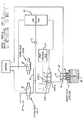
最初に図1を参照すると、本発明によるシステムの典型的な構成のブロック図が見られる。図1に例示する本システムを使用して吸気または排気弁を駆動することができる。このような2段階システムは、3方比例スプール弁24に結合した2つの小型2方デジタル式ラッチング・スプール弁20、22を備えている。この比例スプール弁が、制御容積26に流入出する流れ領域を制御する。この制御容積は、アクチュエータ28に対して作用してエンジン弁30の位置を調節する。この実施形態ではスプリング・リターン32を使用して弁を閉じるが、引き続き説明するように、油圧で閉じる弁を備える実施形態も同様に使用することができる。
【0012】
これらの2つの小型2方デジタル・ラッチング・スプール弁20、22(ここではパイロット弁と呼ぶ)は好ましくは同一の弁であり、かつ1997年6月24日交付の「Didital Two,Three,and Four Way Solenoid Control Valves」と題する米国特許第5,640,987号で開示されている2方弁に従うことが好ましく、その開示を参照により本明細書に組み込む。このような弁は、本発明で使用するように、2つの位置の間で動作可能な2連ソレノイド式高速磁気ラッチング・スプール弁である。第1位置によって第1ポートを第2ポートに結合して、これらの2つのポート間を流体連通し、かつ第2位置によって第1ポートと第2ポートの間の流体連通を遮断する。ポペット弁など他のタイプの弁も使用できるが、上記特許に開示されているタイプの弁が一般的に好ましく、それは、これらの弁では適正な制御が非常に高速であり、これらは磁気ラッチングなどが可能なために省エネルギーであり、かつ使用すれば、既に相対的に暖まっているそれらの動作環境においてさらに加熱するのを最小限にするために駆動完了を検知できるからである。(米国特許第5,720,261号および第5,954,030号を参照)。
【0013】
図1の本発明の実施形態では、弁20が、その第1位置にあるとき配管34からドレイン配管またはタンク37(大気圧など相対的に低圧にある)までの液流を許容し、それが第2位置にあるとき配管34からドレイン37までの液流を遮断する。弁22は、それが第1位置にあるとき低圧レール36から配管34までの液流を許容し、それが第2位置にあるとき低圧レール36から配管34までの液流を遮断する。逆止弁23は随意選択であり、通常はこの逆止弁へかかる差圧は弁を開く方向にはないので閉じている。しかし、それが備わることによって、一時的な圧力変動を減衰させかつ圧力変動おけるエネルギーの回復を助長する。
【0014】
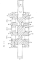
ここで図2を参照すると、図1の3方比例スプール弁24の全体的な構造および機能を例示する図が見られる。この比例スプール弁は内部ハウジング40中にスプール38を含む。このハウジングが、外部ハウジング組立体(図示せず)内部に挿入され、Oリング溝42中のOリングによってポート1、2、3を相互に離し、かつ内部ハウジング40の両端とも隔離する。外部ハウジング組立体は対応する流体接続部を有するとともに、図2のポート1、2、3として示した領域のそれぞれの近くに内部環状溝を含む。それぞれの溝は、内部ハウジング40中のそれぞれの内部領域44、46、48とそれぞれに流体連通するために内部ハウジング40を通る穴に対するマニフォルド領域としての役割を果たす。それぞれのポートから、対応する内部領域44、46または48までの流体連通が、典型的な実施形態では、貫通穴50によってばかりでなく、その穴に直交してそれぞれのポートに対応した貫通穴52を配置することによって実現している。
【0015】
概略的に例示する図2のように、スプール38は、スプールの左端にある有効領域A1を有するピストンとスプールの右側にある有効領域A2を有するピストンに対して作用する流体圧によって内部ハウジング40中に位置決めされる。図2に特に例示するように、スプール38は、本明細書では第1位置と呼ぶ右端の位置にある状態で示してある。その位置は、スプールを駆動するピストンの行程上にあるストップまたはスプール自体に作用するストップによって決まる。この位置では、スプール38がポート3と2の間の流体連通を遮断しており、かつポート2と1の間の流体連通を許容している。明らかなことであるが、スプールがその左端の位置にあるとき、本明細書ではその第2位置と呼ぶが、ポート1と2の間の流体連通が遮断されかつポート2と3の間の流体連通が可能になる。
【0016】
図1の2個の小型2方デジタル式ラッチング・スプール弁20、22を例として示すが、通常スプール弁では、隣接するポート間の流体連通は、スプールが一方の位置ありかつスプールが他方の位置に向かって最初に移動する間は遮断されていることになる。しかし、これらの2つの隣接するポートを結合する領域を分離している、ハウジング中のランドに関連したスプールのリリーフがランドを一旦ブリッジし始めると、これらの2つのポートに結合する領域間の流れ領域が確立し、その流れ領域はスプールがさらに移動するにつれて直線的に増加する。その流れ領域はスプールの全径の周囲の領域なので、一旦開き始めると、スプールが相対的に小さくさらに移動するだけで2つのポート間に相対的に大きな流れ領域が開かれることになる。
【0017】
しかし、この3方比例スプール弁24(図1)では、その細部のいくつかを図2に例示しているが、スプール位置に対する流れ領域を再形成するように、このようなスプール位置に対する流れ領域の変化を修正することができる。典型的な実施形態では、これを図3および4に例示するような態様で達成する。図3がスプール38の斜視図であり、図4がスプール38の中央ランドの一方の縁部の拡大図である。図3で分かるように、スプールの中央ランドは、この中央ランドのそれぞれの端部の回りに等間隔をおいて複数の切り溝54を有し、これらの切り溝によって、スプールのランドの縁部が内部ハウジングのランドの縁部に達する前の、すなわちスプール弁の流れ領域が確立し始める通常のスプール位置で流れ領域が開き始める。
【0018】
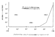
さらに、図4で分かるように、小さい段が、典型的な実施形態の3方比例スプール弁のスプール・ランドに形成してある。したがって、スプールが、内部ハウジングの内径中で緊密にすべり込む外径D0を有する一方で、典型的なスプールの中央ランドの両端に追加的な直径D1、D2、D3を有する。D3はD2よりも小さく、D2はD1よりも小さく、かつD1はD0よりも小さい。これによって、図5および6に例示するように、隣接するポート間の流体連通の開閉時に、スプール位置に対する流れ領域における非線形的な変化が与えられる。これらの図は、3方比例スプール弁中のスプール位置に対する、ポート1と2の間およびポート2と3の間におけるそれぞれの流れ領域を例示する。図5で分かるように、スプールが右端位置にあるとき、ポート1と2の間の流れ領域が最大であり、スプールの右側への最初の動きに対して、最初に相対的に大きな比率で減少し、次に別の移動部分に対してある比率で減少し、次いでスプール移動の残部に対してさらにある比率で実質的にゼロ流れ領域まで減少して、スプールが移動を約40%完了するとき、ポート1と2の間の連通を基本的に遮断する。対照的に図6はポート2と3の間の流れ領域を示すが、それは図5の鏡像である。
【0019】
図5および6からわかるように、本発明の典型的な実施形態では、スプールの最初の閉弁移動時の流れ領域の減少がスプール位置に対して大きな比率で生じ、スプールの位置が増進するにつれて流量の変化が減少して、スプールが移動距離の半ば手前まで達したときに実質的に流れ領域がゼロになり、それによって通常のスプール弁に特徴的な、スプール位置に対する流れ領域の関係を実質的に変更する。また、流れ領域は、最大スプール移動距離の2分の1に達する前に実質的にゼロになるので、ポート1と2の間およびポート2と3の間の流体連通は、スプールがその移動範囲のほぼ中央に位置するとき不能になる、すなわち、遮断される。例示した特定の典型的な実施形態に関しては、ポート1と2の間およびポート2と3の間の実質的な遮断は、スプール位置が、その移動距離の約40%とその移動距離の約60%の間のいずれかの地点にあるときに生じる。流れ領域の他の形状も使用可能であり、あるいは望ましければ何ら整形しなくてもよいことが明らかであるが、何らかの形状を使用して、スプールがその最大位置にあるとき、最大流れ領域を阻害せずに制限領域内のスプール位置における小さな誤差効果を減少させることが好ましい。
【0020】
再び図1を参照すると、低圧レール36中の流体が、それは、例として、20から50バールの圧力を有することができるが、3方比例スプール弁24の右側に結合されて、ピストンの領域A2(図2)に対して作用しスプールをその左端位置に促す。
【0021】
スプール弁22が開きかつスプール弁20が閉じていると仮定すると、低圧レール36内の圧力が、配管34に連通され、したがって比例スプール弁のスプール(図1および図2)を駆動するピストンの領域A1に対して作用する。領域A1は領域A2よりも大きいので、比例スプール弁のスプールがその右端位置に押されてポート1とポート2を結合し、出口に通じるチャンバ26に結合して、弁リターン・スプリング32が弁30を閉位置に押しやることができる。領域A1は、A1−A2=A2となるようにA2の約2倍であることが好ましい。
【0022】
2方弁22が閉じかつ2方弁20が開いている場合は、配管34がドレイン37に通じ、3方比例スプール弁のピストン領域A1(図2)に対して作用する圧力が実質的にゼロになる。しかし、スプール弁の領域A2に対して作用する圧力は、定圧レール36の圧力に等しいので、そのためにスプールに対して不均衡な力が生成されてスプールをその左端位置に押しやる。この位置では、ポート2がポート3と流体連通しているので、高圧レール56内の圧力が制御容積26に連通して弁30を押し開く。
【0023】
例として、弁30が半分開きかつスプール弁20、22が両方とも閉じている場合は、比例スプール弁のポート2がポート1および3から隔離されることになり、制御容積26中の流体が閉じ込められて、弁30をその現位置に維持する。最後に、2方スプール弁20、22は非常に高速の弁なので、比例スプール弁のスプールをその移動距離の最端部の任意の望ましい位置に急速かつ制御可能に配置し、したがって制御容積26に流入出する流体の流量を可変的に制御するような態様で、これらのスプール弁を制御することができる。次いで、これによって開放の程度、開弁のタイミングおよび持続時間、弁の開閉速度の変化(その変化は互いに異なりかつ/またはエンジン動作条件に応じて異なり得る)、およびエンジンの毎分回転数に伴う最終閉弁速度などの弁30の動作パラメータを完全に制御することができる。これによって低騒音動作に関する低エンジン毎分回転数における相対的に低速の閉弁が可能になると共に、依然として、高速エンジン動作回転数に必要な、エンジンの毎分回転数に伴う閉弁速度を増大させることもできる。
【0024】
典型的な実施形態で使用する、低圧レール、高圧レール、およびドレインの中に流れる流体はエンジン作動オイルであるが、望ましければ他の流体を使用することもできる。弁30の制御システム中の流量は、オイルの粘性、したがってオイルの温度、低圧レールと高圧レールの圧力などの様々なパラメータによって異なるので、図1の弁制御システムの動作によってこのような変動値を適切に補償しなければならない。一次近似値として、これらの変動値を適切にモデル化して、現在のエンジン動作パラメータ(回転速度、エンジン負荷、燃料の温度、気温、エンジン・オイルの温度、大気圧など)を考慮すれば、図1に示した制御システムは、エンジンのクランクシャフト角に伴う比例弁のスプール位置の望ましい変化に少なくとも近似的に合わせて弁20、22の動作継続時間を適切に変化させることができる。
【0025】
典型的な実施形態では、小型のホール効果センサ58を弁30用の隣接するアクチュエータ28に位置決めして、フィードバック信号をコントローラに供給する。したがって、弁動作サイクル時の弁の移動を監視しかつ利用して、この弁動作サイクルに関して弁20、22の動作を制御しかつ/またはこの弁動作サイクルに関してより正確に最適弁動作を実現するために、次回の弁動作サイクルにおいて修正を行うことができる。この点に関して、その時点の既存のエンジン動作条件および周辺条件に関する所定値として、または完了した弁動作の変更に関する1つまたは複数のエンジン性能特性に対する増分変化の効果による決定値として、あるいは両者の組合せとして、エンジンのクランク角に対する所定の弁位置の変化に、より適切に適合させること含めて様々な方法のいずれかによって、より最適な動作を決定することができる。
【0026】
2つ(または2つ以上)の弁を単一の比例弁24によって同時に駆動している場合は、位置センサ(ホール効果センサまたは他の位置センサ)などのセンサを弁の一方のみにまたは両方に使用可能であり、これらの信号の総和によって、これらの2つの弁位置変化のより適切な平均値を示し、かつ信号の差異によって動きの悪い弁などの障害を検出する。1個の(または複数の)位置センサが好ましいが、位置に変換するための積分時間は短いので、速度センサなど、他のタイプのセンサを使用することもできる。この点に関して、それぞれの弁動作サイクルの最後に、制御弁22を駆動して配管34を低圧レール36に結合しかつ制御弁20を駆動して配管34をドレイン37から連結解除し、スプール38を図1に概略的に示す位置にあるストップまで移動させる。これによって、弁動作サイクルごとの所定のスプールおよびパイロット弁の開始点が与えられ、スプール弁位置の誤差が弁動作サイクルごとに蓄積することがない。所望であれば、センサを使用して比例スプール弁のスプール38の位置を検知することもできるが、それは好ましくない。
【0027】
したがって、2つの小型ラッチング弁20、22(本明細書では時にパイロット弁と呼ぶ)が、比例弁24の位置を制御する。特に、供給パイロット弁22によって、低圧レール36(約20から50バール)と、比例3方弁を移動させるために使用する第1ピストンとの間の液体の流れを可能にする。逃がしパイロット弁20によって、ピストンから大気圧の出口までの液流を可能にする。これらのパイロット弁を使用して、比例弁の位置を急速かつ正確に変化させることができる。比例弁の位置は、図5および6で注目した3つの流れ状態全体を通じて無限に変化し得る。すなわち、
状態1:高圧レール56(約100から240バール)からの高圧流体を高圧レールからエンジン弁駆動ピストン上方の制御容積26まで流すことができる。
状態2:比例弁のスプール38が強制停止位置の間の中央に位置し、エンジン弁駆動ピストン上方の制御容積中に流体を閉じ込めかつ油圧ロックを生成する。
状態3:エンジン弁駆動ピストン上方の制御容積26中の流体を大気圧に通じさせる。
【0028】
比例弁が状態2から状態3に移行するとき、高圧レール56からの高圧流体がエンジン弁駆動ピストン上方の制御容積26中へと通過できる領域が非線形的に増加する。(図6参照)。同様に、比例弁が状態2から状態1に移行するとき、流体がエンジン弁駆動ピストンの上方の制御容積26からドレイン37まで通過できる領域が非線形的に増加する(図5参照)。したがって、比例スプール弁の幾何学形状は高いゲインと低いゲインの領域を有するように設計されている。この低いゲインの領域が離座および着座速度に関する精密な制御を行い、他方で高いゲインの領域が最大エンジン弁速度を実現するのに必要な大きな流れ領域となる。これによって着座および離座時にエンジン弁のより正確な制御が助長される。適切な着座速度および弁のオーバラップをエンジン回転数および温度の全域を通して実現するように、これらの領域はより正確でなければならない。
【0029】
典型的な油圧システムの機能をより適切に説明するために、以下の説明によって、完全なエンジン弁動作サイクルを通して本システムを調べ、ノーダル油圧シミュレーション(nodal hydraulics simulation)からの結果を模倣する。この特定のシミュレーション・モデルには、低エンジン回転数におけるシミュレーションも実施したが、毎分6000回転のエンジン回転数で、100℃のOW30合成モータ・オイルを使用した。
【0030】
典型的な弁の事象を以下のように説明することができる。最初に、(図1に例示するように)供給パイロット弁22を開きかつ逃がしパイロット弁20を閉ざす。これによって比例弁スプールを逃がし(右端)位置(状態3、図5および6)に保つ。特に、エンジン弁駆動ピストン容積26と出口37の間の流れ領域が最大値にあり(状態3、図6)、かつエンジン弁駆動ピストン制御容積と高圧レールの間の領域が閉じている(状態3、図5)。したがって、エンジン弁はリターン・スプリング32によってその弁座に対して強制的に閉じられている。
【0031】
開弁を開始すると、供給パイロット弁22が開き、かつ逃がしパイロット弁20が閉じる。これによって、比例スプール弁から出口までの液流が可能になる。したがって、比例スプールが状態3から移動を開始する。逃がしパイロット弁20は、比例スプールが状態2を通過して状態1に移行するのに十分に長く開いたままになっている。しかし、比例弁は、状態1の低いゲインの領域におけるごく小さい流れ領域が高圧レール(図5)とエンジン弁駆動ピストン制御容積26との間で開くまで移動できるだけである。その結果、エンジン弁が低速で離れる。このような離座速度は、比例弁の停止位置に応じて異なる。次いで、比例スプールが、高圧レールとエンジン弁駆動ピストンの制御容積の間でより大きな流れ領域を開ける位置まで移動するために、逃がしパイロット弁20が再び開く。その結果、エンジン弁が最初に低速で離座した後で急速に開く。
【0032】
ここでエンジン弁は、望ましい高さで、この特定の例では、11mmで停止しなければならない。このために、比例スプールは、エンジン弁上方の制御容積が油圧によってロックされる状態2にまで移動させられる。これは必要な時間の長さにわたって、逃がしパイロット弁20を閉じかつ供給パイロット弁22を開くことによって実現する。エンジン弁は、それが強制的に戻されるまでこの位置に留まることになる。この時点で、エンジン弁中の運動エネルギーが、制御容積中の流体とエンジン弁のリターン・スプリングの位置エネルギーへ完全に転換される。運動エネルギーと位置エネルギーの間のこのような交換は、制御容積が油圧によってロックされている間に数回発生するが、それによってエンジン弁位置のわずかな変動が生じる恐れがある。このような効果を抑制しかつ比例弁スプール中にいくらかの運動エネルギーを回復するために、エンジン弁アクチュエータの制御容積26と高圧レール56の間に、動作中に発生する恐れのある高圧スパイクを減衰するための逆止弁を配置することもできる。
【0033】
次に、比例弁を状態3の高いゲインの領域まで移動させるほど十分に長く供給パイロット弁20を再び開き、次いで少なくとも逃がしパイロット弁22が再び開く前に閉じる。繰り返して言えば、この時点でエンジン弁制御容積26と出口37の間の流れ領域が最大値である。したがって、エンジン弁は弁スプリング中に保存されているエネルギーによってその弁座に向かって急激に加速されることになる。
【0034】
弁を望ましい速度で着座させるためには、エンジン弁制御容積26と出口37を結合する流れ領域を制限しなければならない。これは、比例弁を状態3における低いゲインに再び位置決めするために、短時間逃がしパイロット弁20をもう一度開くことによって実現する。このような着座速度は、この領域における比例弁の停止位置に応じて変化する。
【0035】
これによって1エンジン弁サイクルが完了する。次の事象のためのシステムを準備するために、すべての構成要素をそれらの初期状態に再び位置決めすることになる。所定位置から外れている唯一の構成要素は比例弁である。供給パイロット弁22を再び開き、比例弁を状態3における最大流れ領域の位置に戻す。これによってそれぞれの弁の事象の始まりにおける基準点が再び確立され、比例弁の位置決め誤差が弁サイクルごとに蓄積することがない。このような方式で、様々なエンジン回転数、負荷、および温度おける望ましい着座速度が、比例スプールが停止する位置を変更することによって実現可能である。これは所望ならば低圧レールの圧力を変更することによってさらに助長することが可能であり、したがって比例スプール弁のより精密な制御を達成することができる。
【0036】
上に説明した本システムの1つのシミュレーションでは、図7に例示するように、2つの同心ピストンからなるエンジン弁アクチュエータを使用する。エンジン弁をそのストローク全体を通して駆動するために圧力にさらされる比較的大きな領域を有する1つのアクチュエータを使用する代わりに、機械的な停止位置に達する前にピーク速度を最初に実現するためのみに大型ピストン(ブースト・ピストン60)を使用し、他方でストロークの残りを小型の入れ子式ピストン(駆動ピストン62)を使用して達成する。特に、エンジン弁、具体的には排気弁がその弁座から離れ始めるとき、シリンダ内圧力が実質的に残存している。さらには、最大エンジン弁加速度もこの時点で必要になる。したがって、エンジン弁をそのストロークの初期部分を通して駆動するためにはより大きな力が必要であり、他方でストロークの残りに必要な力ははるかに小さい。本発明のシステムは、1つのアクチュエータのみを使用すれば同様に機能することになるので、2つの同心ピストン設計の使用に依存することはない。しかし、2つの同心ピストン設計は、弁サイクルごとの高圧レールからの流体が少なくてすみ、したがって弁動作に必要なエネルギーが少ない。
【0037】
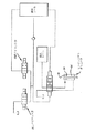
スプリング・リターン弁ではなく、図8に示すように、油圧によって戻すエンジン弁も使用可能である。この実施形態では、弁アクチュエータが断面領域A2を有するピストン・ロッド66の上に断領域A1を有するピストン64を備えている。チャンバ68が高圧レールに恒久的に結合され、かつチャンバ70が高圧レールと出口の間で比例弁によって切換可能である。したがって、最大開弁力は、高圧レールの圧力のA2倍に等しく、かつ最大閉弁力は、高圧レールの圧力のA1−A2倍に等しい。スプリング力とストロークの間の関数的な関係のために、より小さい直径のアクチュエータを備える油圧式戻し弁と本質的に同じ弁動力性能を実現することができる。
【0038】
リターン・スプリングでは、ピーク・シリンダ圧に対して最大に加速するために大きな弁開放力が望ましいとき、スプリングの閉弁力は最小値にある。油圧による戻しでは、油圧式戻しエンジン弁の閉弁力は一定であり、したがって弁が着座しているときのスプリングの閉弁力よりも大きいことになる。したがって、機械的なスプリングに特徴的な力が、単一のピストン戻し機構よりもエンジン弁を戻すためには望ましい。
【0039】
クローズド・センタ3方比例弁を使用する代わりに、クローズド・センタ4方比例弁(図9)を使用して油圧式の戻しシステムを構成することもできる。クローズド・センタ3方比例弁と同様に、その位置を3つの流れ状態全体を通して無限に変化させることができる。
状態1:高圧レールからエンジン弁駆動ピストン64の上の制御容積70まで高圧流体を流すことができると共に、エンジン弁駆動ピストン64の下方で作用するチャンバ68中の流体がタンクに通じている。
状態2:比例弁がその強制停止位置の間の中央に位置し、エンジン弁駆動ピストン上方の制御容積70中とエンジン弁駆動ピストン下方の制御容積68中に流体を閉じ込め、油圧ロックを生成する。
状態3:エンジン弁駆動ピストン上方の制御容積70内の流体を大気圧に通じさせ、高圧流体を高圧レールからエンジン弁駆動ピストン64下方の制御容積68まで流す。
【0040】
比例弁が状態2から状態1へ移行すると、高圧流体がエンジン弁駆動ピストン64上方の制御容積70中へと通過できる領域が非線形的に増加する(図5および6と同様に)。同時に、エンジン弁駆動ピストン64下方の流体とタンクの間の流れ領域が非線形的に増加する。同様に、比例弁が状態2から状態3へ移行すると、流体がエンジン弁駆動ピストン64上方の制御容積70からタンクまで通過できる領域が非線形的に増加する。同時にエンジン弁駆動ピストン64下方の流体と高圧レールの間の流れ領域が非線形的に増加する。
【0041】
説明したすべてのシステムでは、制御容積に対抗するために比例弁は油圧力を使用する。別法として、比例弁はまた、スプリングを使用して対抗力の一部または全部を供給することもできる。
【0042】
3方比例弁システムはいずれも従来技術で知られた復元システムを利用する。そのシステムを実装すれば、3方または4方比例弁を駆動するための低圧レールを復元システムの低圧供給源用に使用することができる。
【0043】
本発明は、ディーゼル式やガソリン式エンジンだけでなく、代替燃料を動力源とする同様のエンジンに関しても多くの利点を有する。これらの利点には、
開弁および閉弁時期に関する無限の可変エンジン弁タイミング;
弁座からその最大リフト位置までの無限の可変エンジン弁開放の程度;
無限の可変弁開弁および閉弁継続時間が含まれる。
【0044】
比例3方または4方弁は、弁離座および着座における精密な制御のための低いゲインの流れ領域を有する。それはまた、最大流量のための高いゲインの流れ領域を有し、エンジン弁の速度を増加させてエンジン・シリンダ内への空気流量を最大化することができる。
【0045】
本システムによって、エンジン弁輪郭を非対称的にすることができる。
【0046】
本システムは、レール圧に関係なくエンジン弁のスルー速度(slew rate)を無限に変化させることができる。
【0047】
本システムは、低速の離座および着座の必要がない。特に、弁は最大加速度で開き始めることができ、あるいは望ましい場合は最大速度で着座することもできる。
【0048】
本システムはラッシュ調節の必要がなく、特に、
本システムは、熱膨張によるエンジン構成要素(特に弁トレイン構成要素)の増大に影響されずかつそれを補償することができる;
本システムは、弁座およびエンジン弁の摩耗によるエンジン弁の後退に影響されずかつそれを補償することができる;さらに
本システムは、初期の組立および製造許容誤差による弁トレイン構成要素間の許容誤差の積重なりに影響されずかつそれを補償することができる。
【0049】
本システムは、温度、経年などによる作動流体の粘度の変化を補償することができる。
【0050】
本システムは、エンジン・シリンダ中に空気を供給する合計時間の最適化が可能であり、したがってエンジン動作条件の全域で燃焼事象を最適化して、
最大出力;
低排出ガス;
燃料/空気の混合を制御することによる排出ガスの低減;
不要なシリンダ内空気の運動の抑制によるヒート・リジェクションの低減;
触媒点火を向上させ、始動時排気ガスを削減する高BMEP燃焼方式をもたらす。
【0051】
本システムは、エンジン・ブレーキによって、特に制動中に噴射器を遮断しかつ圧縮ストロークの頂点で排気弁を開くことによって、圧縮エネルギーを消散させるように動作することができる。
【0052】
エンジン・サイクルの変更が以下のように可能である。
2ストローク動作。
通常のエンジン動作サイクルから1対または複数対のストロークを排除することによる多ストローク動作(例として、2ストロークから4ストローク、4ストロークから6ストロークまたは8ストロークなど)、最小エネルギー損失および/または他の事情のために、弁がこれらのストローク対の間は制御されている。
本システムによる内部排気ガス再循環(EGR)の実現、したがってEGR弁を除去することができる。
可変圧縮比。
ミラー・サイクル動作、すなわち、最大熱力学的効率のために高膨張率による最大シリンダ圧制御。
アトキンソン・サイクル動作。
不要なシリンダ内空気の運動の抑制によるヒート・リジェクションの低減。
触媒点火を向上させ、始動排ガスを削減する高BMEP燃焼方式。
クランキングの向上およびコールド・スタート。
始動時/低温アイドル時/高高度での運転時の白煙およびディーゼル「燃料」臭の低減。
高高度での補償。
自動車の負荷/運転サイクルに、より適合するための可変トルク曲線。
より快適な運転性、自動車に使用可能な燃料の経済性向上のために低速におけるトルクの増大を可能にする。
【0053】
本システムは、逐次配分ポンプによってより効率的に動作する。
【0054】
低圧レールをエンジン弁アクチュエータの戻り流量によって供給するアキュムレータと置き換えることができる。
【0055】
エンジン弁において空気の流量調整ができるようにエンジン弁の動きを変更できるので、スロットル本体を排除することができる。
【0056】
すべてのエンジン動作条件で過給機の動作を最適化することができる。
【0057】
自動車燃料を節約するためにシリンダ動作を停止する。
【0058】
本2段階システムは、非常に高いエンジン回転数(アイドル速度から毎分10,000回転まで)でエンジン弁を十分に制御することができる。さらには、弁の離座および着座の限界領域を正確かつ精密に制御すると共に、弁タイミング、継続時間および高さを無限に変えることができるという特徴を備えることができる。本システムはまた、すべてのエンジン回転数において弁タイミングおよび持続時間を調節して燃焼室に流入出する流量の動的効果を最大化することによって、エンジン回転数の全域を通じてエンジンのシリンダに供給できる空気量を顕著に増加させる能力を有する。
【0059】
本発明の典型的な実施形態および様々な代替実施形態を本明細書において開示してきたが、本発明の趣旨および範囲から逸脱することなく、その形態および細部に様々な変更を加え得ることは当業者には明らかであろう。
【図面の簡単な説明】
【図1】
本発明によるシステムの典型的な構成を示すブロック図である。
【図2】
図1の3方比例スプール弁24の一般的な構造および機能を示す図である。
【図3】
図2の比例弁のスプール38を示す斜視図である。
【図4】
図3のスプール38の中央ランドの縁部を示す拡大図である。
【図5】
高圧レールと弁アクチュエータのチャンバ26の間における、比例弁24によって備わるスプール位置に対する流れ領域をそれぞれに示すグラフである。
【図6】
弁アクチュエータのチャンバ26と出口37の間における比例弁24によって備わるスプール位置に対する流れ領域をそれぞれに示すグラフである。
【図7】
本発明で使用可能な2つの同心ピストンからなるエンジン弁アクチュエータを示す断面図である。
【図8】
クローズド・センタ3方比例弁を使用する、油圧によって戻すエンジン弁を制御する本発明の一実施形態を示すブロック図である。
【図9】
クローズド・センタ4方比例弁を使用する、油圧によって戻すエンジン弁を制御する本発明の一実施形態を示すブロック図である。[0001]
Background of the Invention
1.Field of the invention
The present invention relates to the field of hydraulic valve drives for internal combustion engines.
[0002]
2.Conventional technology
At present, the piston-type internal combustion engines, which are the subject of the present invention, are now widely used in automobiles, trucks, buses and various other mobile and stationary power systems. Such engines include general gasoline and diesel engines, as well as similar engines that operate on different fuels, such as liquid propane. These engines typically use intake and exhaust valves that are pushed into a closed position by springs and open directly or indirectly at appropriate times by camshafts driven by the engine crankshaft. In two-stroke engines, such as two-stroke diesel engines, the camshaft rotates synchronously with the engine crankshaft, while in four-stroke engines, the camshaft has a two-to-one reduction drive system (gear or chain or Belt, etc.) and rotates at half the speed of the engine crankshaft.
[0003]
Driving the camshaft of an engine valve has historically had several advantages, which for decades have become quite versatile in such engines. These advantages are particularly reliable, given the current state of the art of such cam-driven valve systems. Considering the state of development and production, cam drive is relatively economical. Cam drive also has the advantage that the cam can be shaped to provide a smooth curve that determines the valve position with respect to the camshaft angle. This allows the valve to be released at a relatively low speed, at low engine speeds, to close at a low speed as well as a low speed initial opening, thereby minimizing the noise generated. It also provides for fast opening and closing of the valve at high engine speeds required to maintain the same valve timing throughout the operating range of engine speed.
[0004]
Cam driven valve systems also have some limitations that are becoming increasingly problematic. In particular, the optimal valve timing is not constant throughout the operating range of the engine. For example, the valve timing at which the maximum output is at a certain engine speed is not the same as the valve timing at which the maximum output is at another engine speed. Thus, while classic cam-driven valve systems use compromised valve timing to provide reasonable performance over a reasonable range of engine operating conditions, on the other hand, for most if not none of these conditions, May not be optimal. Further, from the viewpoint of engine exhaust gas, the valve timing at which the maximum output is obtained at an arbitrary engine speed may not be optimal. For any given engine speed, the optimal valve timing must depend on the engine load and possibly other parameters such as air temperature, air pressure, engine temperature, etc.
[0005]
In recent years, mechanisms have been introduced that attempt to compensate for some of the limitations of fixed timing cam valve systems. These mechanisms include a mechanism for changing the valve timing (but not the valve opening time related to the camshaft angle) with the engine speed and a mechanism for increasing the valve opening time. However, such mechanisms tend to be complex, the valve opening distance is fixed at all engine operating speeds, and is limited to the number and range of variable values so that optimization of valve operation can be undertaken. There is.
[0006]
Recently, various hydraulic systems for driving valves have been proposed. These systems offer the possibility to control the valve drive parameters more flexibly over a range of different engine operating parameters. The present invention is an improvement on these systems.
[0007]
Summary of the Invention
Hydraulic engine valve drive system and method for an internal combustion engine. The system uses a proportional valve to regulate the flow of working fluid into and out of a hydraulic actuator that controls engine valve position. The position of the proportional valve is controlled by the high speed valve to control various engine valve parameters, including the unseating and seating speed of the engine valve. By returning all valves to a known starting position during an engine valve event, the accumulation of errors in proportional valve positioning is avoided. An embodiment is disclosed that uses a spool valve for high speed and proportional valves and a spring return and hydraulic return for engine valves.
[0008]
To improve control over engine valve operation, a specially formed spool on the proportional valve is used to create a flow area for the spool position. This allows the flow area for the movement of the spool to be more progressively restricted for a selected portion of the possible spool positions, and when the spool is at its maximum position, without impeding the maximum flow area. The effect of small errors in spool position in such areas is reduced.
[0009]
Various other alternative embodiments are disclosed.
[0010]
Detailed Description of the Preferred Embodiment
The present invention is a hydraulic valve actuation system for operating one or more intake valves or one or more exhaust valves in a piston type internal combustion engine, the system comprising: valve timing, valve opening time, degree of opening, And provide full flexibility in opening and closing speed. The operation over the desired range of these and other parameters can be controlled for all engine operating conditions and, more importantly, optimized. Such optimization also includes the ability to incrementally adjust valve operation based on valve operation during a previous valve operation cycle. This is achieved by controlling the position of the proportional valve by using a pilot valve to control the operating parameters of the intake or exhaust valve. In this regard, reference to "an intake valve" or an "exhaust valve" in this specification and in the claims, unless otherwise specified by the context in which the phrase is used, a single cylinder of an internal combustion engine One or more intake valves, or one or more exhaust valves of one cylinder of an internal combustion engine. An exemplary embodiment of the present system, sometimes referred to herein as a "two-stage" system, is described in detail below.
[0011]
Referring first to FIG. 1, a block diagram of a typical configuration of a system according to the present invention is seen. The system illustrated in FIG. 1 can be used to drive intake or exhaust valves. Such a two-stage system includes two small two-way digital
[0012]
These two small two-way digital
[0013]
In the embodiment of the invention of FIG. 1,
[0014]
Referring now to FIG. 2, there is seen a diagram illustrating the overall structure and function of the three-way
[0015]
As schematically illustrated in FIG. 2, the
[0016]
Although the two small two-way digital latching
[0017]
However, in this three-way proportional spool valve 24 (FIG. 1), although some of its details are illustrated in FIG. 2, the flow area for such a spool position is reshaped to recreate the flow area for such a spool position. Changes can be corrected. In an exemplary embodiment, this is accomplished in a manner as illustrated in FIGS. FIG. 3 is a perspective view of the
[0018]
In addition, as can be seen in FIG. 4, a small step is formed in the spool land of the exemplary embodiment three-way proportional spool valve. Thus, the outer diameter D where the spool slides tightly within the inner diameter of the inner housing.0While having an additional diameter D at both ends of the central land of a typical spool.1, D2, D3Having. D3Is D2Smaller than D2Is D1Smaller than and D1Is D0Less than. This provides a non-linear change in the flow area with respect to spool position when opening and closing fluid communication between adjacent ports, as illustrated in FIGS. 5 and 6. These figures illustrate the respective flow areas between
[0019]
As can be seen from FIGS. 5 and 6, in an exemplary embodiment of the present invention, the decrease in flow area during the initial valve closing movement of the spool occurs at a large ratio to spool position, and as the position of the spool increases, When the change in the flow rate is reduced, the flow area becomes substantially zero when the spool reaches halfway of the travel distance, thereby substantially reducing the relationship between the flow area and the spool position, which is characteristic of a normal spool valve. Change. Also, since the flow area is substantially zero before reaching one half of the maximum spool travel, fluid communication between
[0020]
Referring again to FIG. 1, the fluid in the
[0021]
Assuming that the
[0022]
When the two-
[0023]
As an example, if
[0024]
The fluid flowing in the low pressure rail, high pressure rail, and drain used in the exemplary embodiment is engine operating oil, although other fluids can be used if desired. Since the flow rate in the control system of the
[0025]
In an exemplary embodiment, a small
[0026]
If two (or more) valves are driven simultaneously by a single
[0027]
Thus, two
State 1: High pressure fluid from the high pressure rail 56 (about 100 to 240 bar) can flow from the high pressure rail to the
State 2: The
State 3: The fluid in the
[0028]
As the proportional valve transitions from
[0029]
To better illustrate the functioning of a typical hydraulic system, the following description examines the system through a complete engine valve operating cycle and mimics the results from a nodal hydraulics simulation. The simulation at low engine speed was also performed for this particular simulation model, but using 100 ° C. OW30 synthetic motor oil at an engine speed of 6000 revolutions per minute.
[0030]
A typical valve event can be described as follows. First, the
[0031]
When the opening of the valve is started, the
[0032]
Here, the engine valve must stop at the desired height, 11 mm in this particular example. To this end, the proportional spool is moved to a
[0033]
The
[0034]
In order for the valve to seat at the desired speed, the flow area connecting engine
[0035]
This completes one engine valve cycle. All components will be repositioned to their initial state to prepare the system for the next event. The only component that is out of place is the proportional valve. The
[0036]
One simulation of the system described above uses an engine valve actuator consisting of two concentric pistons, as illustrated in FIG. Instead of using one actuator with a relatively large area exposed to pressure to drive the engine valve throughout its stroke, a large size only to achieve peak speed first before reaching the mechanical stop position A piston (boost piston 60) is used, while the rest of the stroke is achieved using a small nested piston (drive piston 62). In particular, when the engine valve, and in particular the exhaust valve, begins to move away from its valve seat, the pressure in the cylinder substantially remains. Further, a maximum engine valve acceleration is also required at this point. Therefore, more force is required to drive the engine valve through the early part of its stroke, while much less force is needed for the rest of the stroke. The system of the present invention does not rely on the use of two concentric piston designs, since it would function similarly using only one actuator. However, the two concentric piston designs require less fluid from the high pressure rail for each valve cycle and therefore require less energy for valve operation.
[0037]
Instead of a spring return valve, it is also possible to use an oil-returned engine valve as shown in FIG. In this embodiment, the valve actuator has a cross-sectional area A2Area A on the
[0038]
With a return spring, the closing force of the spring is at a minimum when a large valve opening force is desired to accelerate to a maximum relative to the peak cylinder pressure. In hydraulic return, the closing force of the hydraulic return engine valve is constant and therefore greater than the closing force of the spring when the valve is seated. Therefore, the forces characteristic of a mechanical spring are more desirable for returning the engine valve than a single piston return mechanism.
[0039]
Instead of using a closed center three-way proportional valve, a hydraulic return system may be configured using a closed center four-way proportional valve (FIG. 9). Like a closed center three-way proportional valve, its position can be changed indefinitely through all three flow states.
State 1: High pressure fluid can flow from the high pressure rail to the
State 2: The proportional valve is centered between its forced stop positions, traps fluid in the
State 3: The fluid in the
[0040]
As the proportional valve transitions from
[0041]
In all described systems, the proportional valve uses hydraulic pressure to counter the control volume. Alternatively, the proportional valve may also provide some or all of the opposing force using a spring.
[0042]
All three-way proportional valve systems utilize restoration systems known in the art. Once the system is implemented, a low pressure rail for driving a three- or four-way proportional valve can be used for the low-pressure supply of the restoration system.
[0043]
The invention has many advantages not only for diesel and gasoline engines, but also for similar engines powered by alternative fuels. These benefits include:
Infinite variable engine valve timing for opening and closing timing;
Degree of infinite variable engine valve opening from the valve seat to its maximum lift position;
Infinite variable valve opening and closing durations are included.
[0044]
Proportional three-way or four-way valves have a low gain flow region for precise control in valve unseating and seating. It also has a high gain flow region for maximum flow and can increase engine valve speed to maximize air flow into the engine cylinder.
[0045]
The system allows the engine valve profile to be asymmetric.
[0046]
The system is capable of infinitely changing the slew rate of the engine valve regardless of the rail pressure.
[0047]
The system eliminates the need for low speed uncoupling and sitting. In particular, the valve can begin to open at maximum acceleration or, if desired, sit at maximum speed.
[0048]
The system does not require lash adjustment, especially
The system is unaffected by and can compensate for the increase in engine components (particularly valve train components) due to thermal expansion;
The system is not affected by and can compensate for retraction of the engine valve due to wear of the valve seat and the engine valve;
The system is insensitive to and can compensate for the stacking of tolerances between valve train components due to initial assembly and manufacturing tolerances.
[0049]
The system can compensate for changes in the viscosity of the working fluid due to temperature, aging, and the like.
[0050]
The system is capable of optimizing the total time to supply air into the engine cylinder, thus optimizing combustion events across engine operating conditions,
Maximum output;
Low emissions;
Reduction of emissions by controlling fuel / air mixing;
Reduction of heat rejection by suppressing unnecessary air movement in the cylinder;
This results in a high BMEP combustion scheme that improves catalyst ignition and reduces startup emissions.
[0051]
The system can be operated to dissipate the compression energy by engine braking, particularly by shutting off the injectors during braking and opening the exhaust valve at the top of the compression stroke.
[0052]
Changes to the engine cycle are possible as follows.
Two-stroke operation.
Multi-stroke operation (eg, 2 to 4 strokes, 4 to 6 strokes, or 8 strokes, etc.) by eliminating one or more pairs of strokes from a normal engine operating cycle, with minimal energy loss and / or other For reasons, the valve is controlled during these stroke pairs.
The implementation of the internal exhaust gas recirculation (EGR) by the present system, and thus the EGR valve can be eliminated.
Variable compression ratio.
Miller cycle operation, ie, maximum cylinder pressure control with high expansion rate for maximum thermodynamic efficiency.
Atkinson cycle operation.
Reduction of heat rejection by suppressing unnecessary air movement in the cylinder.
High BMEP combustion system that improves catalyst ignition and reduces starting exhaust gas.
Improved cranking and cold start.
Reduced white smoke and diesel "fuel" odor during start-up / cold idle / high altitude operation.
High altitude compensation.
Variable torque curve to better fit the load / driving cycle of the vehicle.
It allows for increased torque at low speeds for more comfortable driving and improved economics of the fuel available to the vehicle.
[0053]
The system operates more efficiently with a sequential pump.
[0054]
The low pressure rail can be replaced by an accumulator which is supplied by the return flow of the engine valve actuator.
[0055]
Since the movement of the engine valve can be changed so that the air flow rate can be adjusted in the engine valve, the throttle body can be eliminated.
[0056]
The operation of the turbocharger can be optimized under all engine operating conditions.
[0057]
Stop cylinder operation to save vehicle fuel.
[0058]
The two-stage system is capable of adequately controlling engine valves at very high engine speeds (from idle speed to 10,000 revolutions per minute). Furthermore, it is possible to provide a feature that the limit region of the unseating and seating of the valve is accurately and precisely controlled, and the valve timing, the duration and the height can be changed indefinitely. The system can also supply engine cylinders across engine speed by adjusting valve timing and duration at all engine speeds to maximize the dynamic effect of flow into and out of the combustion chamber. Has the ability to significantly increase air volume.
[0059]
While exemplary embodiments of the present invention and various alternative embodiments have been disclosed herein, it will be appreciated that various changes can be made in form and detail without departing from the spirit and scope of the invention. It will be clear to the trader.
[Brief description of the drawings]
FIG.
1 is a block diagram showing a typical configuration of a system according to the present invention.
FIG. 2
FIG. 2 is a diagram illustrating a general structure and function of the three-way
FIG. 3
FIG. 3 is a perspective view showing a
FIG. 4
FIG. 4 is an enlarged view showing an edge of a center land of the
FIG. 5
4 is a graph showing the flow area between the high pressure rail and the
FIG. 6
Fig. 4 is a graph respectively showing the flow area for the spool position provided by the
FIG. 7
1 is a cross-sectional view showing an engine valve actuator including two concentric pistons that can be used in the present invention.
FIG. 8
FIG. 2 is a block diagram illustrating one embodiment of the present invention for controlling an engine valve that returns by hydraulic pressure using a closed center three-way proportional valve.
FIG. 9
FIG. 2 is a block diagram illustrating one embodiment of the present invention for controlling an engine valve that returns by hydraulic pressure using a closed center 4-way proportional valve.
Claims (6)
第1圧力下にある流体源を油圧アクチュエータに結合する第1位置と油圧アクチュエータを第2圧力下にある流体タンクに結合する第2位置との間で油圧によって移動可能なスプールを有し、第2圧力が第1圧力よりも小さい、比例スプール弁と、
第1位置と第2位置の間でスプール位置を油圧によって制御する電気制御式弁と、
弁を閉位置に戻す弁リターンとを備えるエンジン弁を開く装置。A hydraulic actuator, wherein the hydraulic actuator is disposed relative to the valve to urge the valve toward a valve open position by fluid pressure in the hydraulic actuator;
A spool that is hydraulically movable between a first position that couples the fluid source under the first pressure to the hydraulic actuator and a second position that couples the hydraulic actuator to the fluid tank under the second pressure; A proportional spool valve, wherein the second pressure is less than the first pressure;
An electrically controlled valve that hydraulically controls a spool position between a first position and a second position;
A device for opening an engine valve comprising a valve return for returning the valve to a closed position.
弁に対して配置した油圧アクチュエータを備えて油圧アクチュエータ中の流体圧力によって弁を弁開位置に促すステップと、
第1圧力下にある流体源を油圧アクチュエータに結合する第1位置と油圧アクチュエータを第2圧力下にある流体タンクに結合する第2位置との間で油圧によって移動可能なスプールを有する比例スプール弁に油圧アクチュエータを結合するステップであって、第2圧力が第1圧力よりも小さいステップと、
電気制御式弁によって第1位置と第2位置の間でスプールの位置を油圧によって制御するステップとを含む方法。A method of opening an engine valve,
Prompting the valve to a valve open position by means of fluid pressure in the hydraulic actuator, comprising a hydraulic actuator disposed relative to the valve;
Proportional spool valve having a spool hydraulically movable between a first position coupling a hydraulic source under hydraulic pressure to a hydraulic actuator and a second position coupling hydraulic actuator to a hydraulic tank under a second pressure Coupling the hydraulic pressure to the second pressure, wherein the second pressure is less than the first pressure;
Hydraulically controlling the position of the spool between the first position and the second position by an electrically controlled valve.
Applications Claiming Priority (2)
| Application Number | Priority Date | Filing Date | Title |
|---|---|---|---|
| US72948700A | 2000-12-04 | 2000-12-04 | |
| PCT/US2001/046686 WO2002046582A2 (en) | 2000-12-04 | 2001-11-30 | Hydraulic valve actuation systems and methods |
Publications (2)
| Publication Number | Publication Date |
|---|---|
| JP2004515681A true JP2004515681A (en) | 2004-05-27 |
| JP2004515681A5 JP2004515681A5 (en) | 2005-04-14 |
Family
ID=24931263
Family Applications (1)
| Application Number | Title | Priority Date | Filing Date |
|---|---|---|---|
| JP2002548287A Pending JP2004515681A (en) | 2000-12-04 | 2001-11-30 | Hydraulic valve drive system and method |
Country Status (6)
| Country | Link |
|---|---|
| US (1) | US20020157623A1 (en) |
| EP (1) | EP1409853B1 (en) |
| JP (1) | JP2004515681A (en) |
| AU (1) | AU2002225937A1 (en) |
| DE (1) | DE60118984T2 (en) |
| WO (1) | WO2002046582A2 (en) |
Cited By (2)
| Publication number | Priority date | Publication date | Assignee | Title |
|---|---|---|---|---|
| JP2012180768A (en) * | 2011-02-28 | 2012-09-20 | Mitsubishi Heavy Ind Ltd | Valve gear of internal combustion engine and valve gear driving method of internal combustion engine |
| JP2012180769A (en) * | 2011-02-28 | 2012-09-20 | Mitsubishi Heavy Ind Ltd | Valve train device of internal combustion engine and method of driving valve train of internal combustion engine |
Families Citing this family (28)
| Publication number | Priority date | Publication date | Assignee | Title |
|---|---|---|---|---|
| US8215292B2 (en) | 1996-07-17 | 2012-07-10 | Bryant Clyde C | Internal combustion engine and working cycle |
| US6739293B2 (en) * | 2000-12-04 | 2004-05-25 | Sturman Industries, Inc. | Hydraulic valve actuation systems and methods |
| ITBO20010092A1 (en) * | 2001-02-20 | 2002-08-20 | Magneti Marelli Spa | ELECTROHYDRAULIC DEVICE FOR ACTIVATING THE VALVES OF A COMBUSTION ENGINE |
| KR20040094419A (en) * | 2002-01-30 | 2004-11-09 | 디이젤 엔진 리타더스, 인코포레이티드 | Engine valve actuation system and method using reduced pressure common rail and dedicated engine valve |
| US7347171B2 (en) * | 2002-02-04 | 2008-03-25 | Caterpillar Inc. | Engine valve actuator providing Miller cycle benefits |
| US6732685B2 (en) * | 2002-02-04 | 2004-05-11 | Caterpillar Inc | Engine valve actuator |
| US6941909B2 (en) * | 2003-06-10 | 2005-09-13 | Caterpillar Inc | System and method for actuating an engine valve |
| US7069887B2 (en) * | 2002-05-14 | 2006-07-04 | Caterpillar Inc. | Engine valve actuation system |
| US7004122B2 (en) * | 2002-05-14 | 2006-02-28 | Caterpillar Inc | Engine valve actuation system |
| GB2391288B (en) * | 2002-07-30 | 2004-12-22 | Lotus Car | An electrically operated valve for controlling flow of hydraulic fluid |
| DE10310300A1 (en) * | 2003-03-10 | 2004-09-23 | Robert Bosch Gmbh | Combustion engine valve actuator control method, in which the work space of the actuator is temporarily connected to a hydraulic fluid accumulator to measure a resultant pressure drop and thus the position of the actuator element |
| US6912458B2 (en) * | 2003-06-25 | 2005-06-28 | Caterpillar Inc | Variable valve actuation control for operation at altitude |
| US7341028B2 (en) | 2004-03-15 | 2008-03-11 | Sturman Industries, Inc. | Hydraulic valve actuation systems and methods to provide multiple lifts for one or more engine air valves |
| US7421981B2 (en) * | 2004-03-17 | 2008-09-09 | Ricardo, Inc. | Modulated combined lubrication and control pressure system for two-stroke/four-stroke switching |
| US7387095B2 (en) | 2004-04-08 | 2008-06-17 | Sturman Industries, Inc. | Hydraulic valve actuation systems and methods to provide variable lift for one or more engine air valves |
| JP2006029247A (en) * | 2004-07-20 | 2006-02-02 | Denso Corp | Stop and start control device for engine |
| JP4583229B2 (en) * | 2005-04-19 | 2010-11-17 | 本田技研工業株式会社 | Valve operating device for internal combustion engine |
| US7555998B2 (en) * | 2005-12-01 | 2009-07-07 | Jacobs Vehicle Systems, Inc. | System and method for hydraulic valve actuation |
| EP2063075A1 (en) | 2007-11-23 | 2009-05-27 | EMPA Eidgenössische Materialprüfungs- und Forschungsanstalt | Fluid actuated valve mechanism |
| GB2466513A (en) * | 2008-12-29 | 2010-06-30 | Mehdi Ansari | Computer controlled hydraulic and mechanical system for variable valve timing, valve lift and valve opening duration in car engines |
| US8412441B1 (en) | 2009-09-09 | 2013-04-02 | Sturman Digital Systems, Llc | Mixed cycle compression ignition engines and methods |
| FI20095970L (en) * | 2009-09-21 | 2011-03-30 | Waertsilae Finland Oy | ARRANGEMENT FOR USING A GAS EXCHANGE VALVE |
| US8689769B2 (en) * | 2010-05-12 | 2014-04-08 | Caterpillar Inc. | Compression-braking system |
| US8939173B2 (en) * | 2010-07-14 | 2015-01-27 | Mac Valves, Inc. | Stepper motor operated balanced flow control valve |
| KR101518907B1 (en) * | 2013-12-17 | 2015-05-11 | 현대자동차 주식회사 | Oil passage for supplying oil |
| DE102016002051A1 (en) * | 2016-02-22 | 2017-08-24 | GM Global Technology Operations LLC (n. d. Gesetzen des Staates Delaware) | Motor vehicle drive train control |
| US10232841B2 (en) * | 2016-11-18 | 2019-03-19 | Ford Global Technologies, Llc | Methods and system for improving response of a hybrid vehicle |
| DE102019201043A1 (en) * | 2019-01-28 | 2020-07-30 | Sms Group Gmbh | Control of hydraulic actuating cylinders in roll stands |
Family Cites Families (5)
| Publication number | Priority date | Publication date | Assignee | Title |
|---|---|---|---|---|
| DE1292493B (en) * | 1964-04-16 | 1969-04-10 | Frisch Geb Kg Eisenwerk | Hydraulic control device for a working piston displaceable in a cylinder |
| US5248123A (en) * | 1991-12-11 | 1993-09-28 | North American Philips Corporation | Pilot operated hydraulic valve actuator |
| US5193584A (en) * | 1992-02-20 | 1993-03-16 | Sauer Inc. | Spool valve and method of making the same |
| US5640987A (en) * | 1994-04-05 | 1997-06-24 | Sturman; Oded E. | Digital two, three, and four way solenoid control valves |
| DE19543080C2 (en) * | 1995-11-18 | 1999-10-28 | Man B & W Diesel Ag | Device for controlling valves of an internal combustion engine, in particular the gas supply valve of a gas engine |
-
2001
- 2001-11-30 AU AU2002225937A patent/AU2002225937A1/en not_active Abandoned
- 2001-11-30 DE DE60118984T patent/DE60118984T2/en not_active Expired - Lifetime
- 2001-11-30 JP JP2002548287A patent/JP2004515681A/en active Pending
- 2001-11-30 EP EP01995378A patent/EP1409853B1/en not_active Expired - Lifetime
- 2001-11-30 WO PCT/US2001/046686 patent/WO2002046582A2/en active IP Right Grant
-
2002
- 2002-03-25 US US10/108,246 patent/US20020157623A1/en not_active Abandoned
Cited By (2)
| Publication number | Priority date | Publication date | Assignee | Title |
|---|---|---|---|---|
| JP2012180768A (en) * | 2011-02-28 | 2012-09-20 | Mitsubishi Heavy Ind Ltd | Valve gear of internal combustion engine and valve gear driving method of internal combustion engine |
| JP2012180769A (en) * | 2011-02-28 | 2012-09-20 | Mitsubishi Heavy Ind Ltd | Valve train device of internal combustion engine and method of driving valve train of internal combustion engine |
Also Published As
| Publication number | Publication date |
|---|---|
| DE60118984D1 (en) | 2006-05-24 |
| DE60118984T2 (en) | 2007-01-11 |
| EP1409853A2 (en) | 2004-04-21 |
| US20020157623A1 (en) | 2002-10-31 |
| EP1409853B1 (en) | 2006-04-19 |
| WO2002046582A2 (en) | 2002-06-13 |
| AU2002225937A1 (en) | 2002-06-18 |
| WO2002046582A3 (en) | 2003-01-16 |
Similar Documents
| Publication | Publication Date | Title |
|---|---|---|
| JP2004515681A (en) | Hydraulic valve drive system and method | |
| US6739293B2 (en) | Hydraulic valve actuation systems and methods | |
| US5937807A (en) | Early exhaust valve opening control system and method | |
| US6925976B2 (en) | Modal variable valve actuation system for internal combustion engine and method for operating the same | |
| EP1936132B1 (en) | Internal combustion engine with intake valves having a variable actuation and a lift profile including a constant lift boot portion | |
| JP4047542B2 (en) | Engine valve actuation system | |
| CN106014522B (en) | Variable valve actuator | |
| US6321701B1 (en) | Lost motion valve actuation system | |
| US7290524B2 (en) | Control apparatus and method for four-stroke premixed compression ignition internal combustion engine | |
| JP2005522622A (en) | Compact idle motion device for variable valve actuation | |
| US6964270B2 (en) | Dual mode EGR valve | |
| KR20050054942A (en) | System and method for internal exhaust gas recirculation | |
| US20050263116A1 (en) | Hydraulic valve actuation systems and methods to provide variable lift for one or more engine air valves | |
| CN101263289B (en) | Control apparatus and control method for internal combustion engine | |
| JPH0510161A (en) | Variable tappet valve system of internal combustion engine | |
| US6899068B2 (en) | Hydraulic valve actuation system | |
| JP3783765B2 (en) | EGR device for turbocharged engine | |
| US8272357B2 (en) | Crossover valve systems | |
| US6315265B1 (en) | Variable valve timing actuator | |
| JPS59131714A (en) | Valve operation switching apparatus for engine with turbocharger | |
| JP2522207Y2 (en) | Variable valve train for engines | |
| JPS5925008A (en) | Valve operation switching device of internal combustion engine | |
| JP3680048B2 (en) | Hydraulic drive fuel injection device | |
| GB2508501A (en) | Valve train facilitating adjustable valve lift via a hydraulic plunger | |
| US7210434B2 (en) | Hydraulic cam for variable timing/displacement valve train |
Legal Events
| Date | Code | Title | Description |
|---|---|---|---|
| A621 | Written request for application examination |
Free format text: JAPANESE INTERMEDIATE CODE: A621 Effective date: 20041101 |
|
| A131 | Notification of reasons for refusal |
Free format text: JAPANESE INTERMEDIATE CODE: A131 Effective date: 20070403 |
|
| A601 | Written request for extension of time |
Free format text: JAPANESE INTERMEDIATE CODE: A601 Effective date: 20070703 |
|
| A602 | Written permission of extension of time |
Free format text: JAPANESE INTERMEDIATE CODE: A602 Effective date: 20070710 |
|
| A02 | Decision of refusal |
Free format text: JAPANESE INTERMEDIATE CODE: A02 Effective date: 20071106 |