【0001】
本発明は請求項1の前文に開示した船舶推進アセンブリの設置装置に関し、この推進アセンブリはモジュラーハウジング構造体、即ち船体の外側に配置されるモータユニットを含む。モータユニットはモータとプロペラを備え、船舶に接続される構造体、特に船舶から外側に延出するアーム形状の構造体に嵌合する。本発明はまた請求項8の前文に開示した方法にも関し、この方法によると、船舶推進装置のモータユニットは船舶に接続される構造体、特に船舶から外側に延出するアーム構造に設置されたりそこから取り外されたりする。本発明はまた、具体的には困難な使用条件下において相互接続可能で且つ互いから取り外し可能な2つの装置間に電気及び/又は流れ媒体を伝送する、請求項10の前文に開示したコネクタプラグ装置にも関する。このコネクタプラグ装置は、本発明の設置装置及び設置方法それぞれを実現するように考案される。
【0002】
プロペラが船体とは別個の構造体に嵌合する船舶推進装置は、海事分野ではよく知られている。多くの場合このような構造体は回転可能で、この構造体を回転させることでプロペラ流を所望の方向に向けることができる。したがってこのように構成された装置は、船舶の推進システムと船舶主操舵装置として同時に機能する。このようなプロペラ装置の特に好適な実施形態はいわゆる「パッド」と呼ばれる別個のハウジング構造体を含み、多くの場合この構造体は流水に対して好ましい形状に設計される。このパッドにはプロペラの駆動モータ(多くの場合電気モータ)が配置される。このような装置の例として、本願の出願人の商標「Azipod」(商標)で市場に出回っている推進システムを挙げることができる。機能上この種の構造体は多数の重要な利点をもたらすため、今日このような推進装置が種々の船舶の大部分に用いられている。
【0003】
今日までこの種の推進装置は、モータ、これに装着されるプロペラ軸及び他の種類の機能的に重要な装置が既存のハウジング構造体における軸構造体の端部に配置され、次いでこのハウジング構造体を水密に閉じるように設置されてきた。しかしながら現場でのこの種の設置を実行できない場合があるため、推進装置の別個のアーム部分に接続されるモジュラーモータユニットを備える装置が同じ出願人によって既に出願されているフィンランド特許出願番号第FI−20000191号に開示されている。
【0004】
本願の目的は、特にモジュラー構造体からなるひとつ又は2つ以上のモータユニットを船舶内の構造体、限定されないが特に船舶から外側に延出するアーム構造体に設置するための特に実用可能な装置を提供することであり、アーム構造体はさらに船舶に対して回転可能なことが好ましい。
【0005】
全ての技術的装置と同様に、船舶の推進装置もまた一定の間隔でメンテナンスを要し、このメンテナンスは乾燥した状態で行うのが最適である。したがって、モータユニットを簡単に且つ安全にオーバーホールし船舶に戻すことができるように、モータユニットを船舶に設置したり該船舶から取り外したりする要求がある。この場合、装置のテストの必要性も存在する。
【0006】
したがって本発明の別の目的は、モータユニットを簡単に設置したり取り外したりできる装置を開示することである。
【0007】
本発明の目的は、モータユニットのテスト、装着、取り外しがモータユニットを開けずにできる装置をさらに開示することである。
【0008】
本発明の別の目的は、モータユニット全体を完全なモジュールとして交換できるためスペアの部品を迅速に交換できる装置を開示することである。
【0009】
本発明の別の目的は、別個のメンテナンスや特別な供給装置を要する装置の必要性を最小にした装置を得ることである。
【0010】
添付の請求項に開示した本発明によって上記の目的を達成することができる。したがって本発明の装置によると、ハウジング構造体はプロペラと反対側の端部に第1の嵌合手段を含み、この第1の嵌合手段は、船舶に接続される構造体に配置された対応する第2の嵌合手段にハウジング構造体を長手方向に嵌合するように構成される。
【0011】
これに対応して本発明の方法によると、モータユニットは構造体に含まれる嵌合片に嵌合し、この構造体が船舶に接続されたり該船舶から取り外されたりし、嵌合や取り外しはモータの軸の方向におけるほぼ長手方向の変位によって行われるため、嵌合片とモータユニットの一端壁のそれぞれにある協働コネクタプラグ手段が船舶に接続される構造体とモータユニットとの間の電源をモータに供給するための接続を確立するのと実質的に同時にこのような接続を開く。
【0012】
これに対応して本発明のコネクタプラグ手段によると、この装置は絶縁物質に埋め込まれた柔軟性嵌合及び変形手段を含み、この絶縁物質はまた嵌合及び適合手段のための弾性手段も形成する。
【0013】
幾つかの好適な実施形態や添付図面を参照して本発明をより詳細に説明する。
図1は、一般的なモータユニット装置の一般的な斜視図を示し、本発明のひとつの実施形態ではひとつのモータユニットが船舶(図示せず)から外側に延出するアーム構造体に設置されている。
図2は、図1の装置の側面図を示す。
図3は、図1及び2の装置を上から見たときの対応図を示す。
図4は、ひとつのモータユニットを意図した、本発明のひとつの実施形態のアーム構造体の斜視図を示す。
図5は、嵌合装置構成を有する図4のアーム構造体を真後ろから見た図を示す。
図6は、図5のアーム構造体の側面図を示す。
図6aは、コネクタプラグ手段の図5のアーム構造体への嵌合の部分拡大図を示す。
図7は、図5のアーム構造体を下から見た図を示す。
図8は、本発明のひとつの実施形態のコネクタプラグ手段装置の概略正面図を示す。
図9は、図8の装置の概略側面図を示す。
図10は、ひとつのモータユニットの嵌合片として機能する、アーム構造体と別個に形成した下部(逆さの状態)の斜視図を示す。
図11は、図10に接続するアーム構造体(同様に逆さの状態)の対応斜視図を示す。
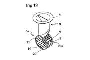
図12は、本発明の別の実施形態である、2つのモータユニットのためのアーム構造体装置の斜視図を示す。
図13は、図12のアーム構造体の正面図(又は裏面図)を示す。
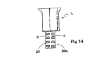
図14は、図12及び13のアーム構造体の対応側面図を示す。
図15は、本発明のひとつの実施形態の単一のコネクタプラグ手段装置の側面図を示す。
図16は、図15のコネクタプラグの断面図を示す。
【0014】
図1によると、本発明の装置は一般にモータユニット1を含み、このモータユニットはハウジング構造体からなり、公知の電気モータを有する。このモータは図2において参照番号25で一般的に示されている。このモータには長手軸26が装着されており、この長手軸は一端部にスラスト軸受24を有する。プロペラ軸26の反対側の端部2には公知のプロペラが嵌合しており、このプロペラは図2において参照番号5で示されている。本発明の好適な実施形態ではモータユニット1はアーム構造体3に嵌合しており、この公知のアーム構造体は例えば図面に示すアダプタリング4によって船体(図示せず)の底部に回転可能に嵌合するのが好ましい。図2はさらに、モータユニット1がプロペラ5と反対側の端部で好ましくは別個に構成されたアーム構造体3のアダプタ片、即ちアーム構造体3の下部6に嵌合している状態を示す。本発明のこの部分には締め付けボルト(図示せず)用の取り付け穴8が外側から設けられており、これらのボルトはモータユニットの端壁7に外側から取り付けられる。閉じたモータユニット1の端壁7がアーム構造体3の下部6の壁も構成し、そのため下部6の内部21に下部6の方向から流れてきた水がモータユニット1、特に軸26のスラスト軸受24を冷却できるように、本装置を構成するのが好ましい。
【0015】
さらに図2に示すように、アーム構造体の下部6は通常開いたままの少なくともひとつのメンテナンス開口9を有するのが好ましく、この開口は装置の外側の水が下部6に流入したり下部6から流出したりできるように冷却水開口としても同時に機能するのが好ましい。ひとつ又は複数の別個の公知の冷却水開口10を、モータユニット1のスラスト軸受24のハウジングに向かって開くように下部6に配置するのが好ましい。軸受には冷却フランジが設けられるのが好ましく、また本発明のひとつの実施形態によると、この軸受は下部6の内部に延出するようにモータユニット1の端壁7に近接して設けられるのが好ましい。冷却水開口はボルトの取り付け穴としても同時に機能するのが好ましい。さらに図3に示すように、アセンブリ全体、特にアーム部分3ができるだけ狭い水流干渉断面を呈するように設計するのが好ましい。
【0016】
本発明の好適なひとつの実施形態のアーム装置3を図4に斜視図で示し、図5にモータユニットを取り付ける方向から見た図で示し、図6と図6Aに側面図で示し、図7に下から見た図で示す。アーム装置3では、アーム構造体3の下部6の周縁20にはモータユニットの締め付けボルト用の穴11が均等に設けられるのが好ましい。本発明の特に好適なひとつの実施形態では、船舶に適したサイズのモータユニット1全てに同一の一連の締め付け穴11が設けられるように、これらの締め付け穴11の位置を標準化している。これに対応して、モータユニット1の他の締め付け及び設置装置12も標準位置、即ち好ましくはモータユニット1のひとつの端部7に配置される。したがって、どんなモータユニット1も図5のシングルエンドアーム構造体3や以下により詳細に説明する図12〜14のダブルエンドアーム構造体に実質的に同じ方法で固定することができる。本発明の装置のために、標準サイズのモータユニット1を開かずに設置することが可能になる。その理由は、締め付けボルトの取り付けや締め付けなどのモータユニットを装着するために必要な手段をアーム構造体3の下部6の方向から実行することができるためである。
【0017】
図5及び6aはさらに、本発明の特に好適な実施の形態、即ち一般的に図8及び9に示すコネクタプラグ手段装置12の詳細を示す。以下に示す特に好適なひとつの実施形態である本発明のコネクタプラグ装置によって、モータユニット1の機能に必要な全ての給電装置や接続手段、例えば電気電源13、モータユニットの機能を制御するのに必要な結合器14、給油や冷却などのための配管15を単一の結合段階で好ましくはモータユニットの嵌合と同時に結合させることができる。したがって、モータユニットの結合を1回の作業段階で行うことができ、このことによって例えば故障の可能性のあるモータユニットとスペアのモータユニット1とを非常に迅速に交換することができる。最初の設置時に同じ利点を既に自ずと得ており、運んできた標準的なモータユニット1を非常に迅速に船舶に設置することができる。
【0018】
本発明の装置は他の利点ももたらす。即ち、製造されたモータユニット1、取り外したモータユニット1又は整備したモータユニット1の設置前テストを非常に簡単に行うことができる。モータユニット1の機能や制御に必要な結合器全てを1回の「プラグアンドプレイ」操作で同時に接続することができるため、この種の結合は実際どこでも、例えばモータのテスト時に実行することができる。その後閉じたモータユニット内で行う操作はないため、テスト済モータは確実に運転状態になる。
【0019】
図8及び9は、本発明のひとつの実施形態の共通する標準的なコネクタプラグ装置の例を示す。図示されるように、このような通過及び結合ユニット12にはシール16を適切に設けることができ、各プラグコネクタ用に配置された別個の設置領域が別個のシール16aでさらに囲まれるのが好ましい。例えば図15及び16により詳細に示すコネクタプラグ18(このようなコネクタプラグは防湿シール17も備える)をこの種のアセンブリに嵌合することができ、そのことによって、1回の同時の動作でコネクタプラグ18に挿入されるモータユニット1側の対応するコネクタプラグ手段(図示せず)が給電、動作及び制御機能全てに対して確実な接続を確立することができる。
【0020】
図10及び11に示すように、アーム装置3の下部6を別個のアダプタ片として構成しこれがモータユニットとの標準的な接続装置8、11、12を含むように、本発明の装置を適切に実現することができる。この場合、アーム3と下部6が例えば別個の成形部品19を用いることによって、且つ/又はこれらの部品を相互関連するように設計することで共に形状固定嵌め合いを形成するように、下部6が船舶に接続される適切で好ましくは回転可能なアーム構造体3に適切に嵌合する。
【0021】
図12〜14は、本発明のアーム構造体3の別の実施形態を示す。この場合、アームアセンブリの下部6aは両側を有するため、ひとつのモータユニット1のプロペラ5と反対の端部7を対向して離間する両締め付け面20、20aそれぞれにいつでも装着することができる。これらの締め付け面20、20aは、締め付けボルト用穴11、また例えばコネクタプラグ手段装置12の位置に関して同じように適切に構成されるため、標準的なモータユニット1をアセンブリの各端部に設置することができる。この場合ボルト用取り付け穴8はアームアセンブリ3の実質的に円筒形であるのが適切な下部6aに配置されるか或いは下部6aの外面に落ち込むように配置されるのが好ましい。その結果、ボルトのモータユニット1の端壁7に対する固定及び締め付けを下部の内部21から行うことができる。
【0022】
本発明の好適な実施形態によると、モータユニット1のプロペラ5の反対側の軸受24の冷却装置は、公知の軸受24がアームアセンブリ3の下部6、6aを流れる水で冷却されるように実現される。このため下部6、6aには例えばフロー開口9、10が設けられ、これらの機能を適切なポンプなどの手段(図示せず)によってさらに強調することができる。したがって、軸受24を周囲の水で直接冷却するように構成することで、技術的に困難な軸受24の油循環冷却装置を不必要であるとして通常省くことができる。
【0023】
本発明の一般的な装置を実現するために特別な接続装置18がさらに考案されており、これを図15及び16により詳細に示す。この装置は少なくとも幾分可とう性があり、好ましくはやや弾性のある対向して協働する公知の結合舌22を備え、これらの間に協働する相手(図示せず)、例えばモータユニット1の端壁7の接続装置12を補う相手の結合舌が圧入されて特に電気接続を確立する。既知のことから明らかであるように、結合器の防湿シールとして使用する絶縁物質17からなる部分にはリップシール23が設けられることが好ましく、これが同時に結合舌22の弾性部分として機能するように本発明のコネクタプラグ装置を実施する。したがって本発明の接続装置の絶縁部分17は、協働する相手の結合舌の両側から互いに向かって結合舌22を押圧することで、結合舌間の接続を密閉すると同時に確実なものとする。
【0024】
主に船舶から外側に延出しまた好ましくは例えば垂直方向に回転可能なアーム構造体に関して本発明を上記に説明してきた。しかしながら、添付の請求項の範囲内ならば多くの他の方法でも本発明を実施できることは当業者には明らかである。したがって、船舶の固定された構造体にモータユニットを設置する場合、例えば取り外した従来通りのプロペラアセンブリを船舶の船体に直接戻したり船舶の船体に装着される下部6に対応する別個のアダプタ片に戻す場合にも対応する装置を実施できることは明らかである。
【図面の簡単な説明】
【図1】
一般的なモータユニット装置の一般的な斜視図を示し、本発明のひとつの実施形態ではひとつのモータユニットが船舶(図示せず)から外側に延出するアーム構造体に設置されている。
【図2】
図1の装置の側面図を示す。
【図3】
図1及び2の装置を上から見たときの対応図を示す。
【図4】
ひとつのモータユニットを意図した、本発明のひとつの実施形態のアーム構造体の斜視図を示す。
【図5】
嵌合装置構成を有する図4のアーム構造体を真後ろから見た図を示す。
【図6】
図5のアーム構造体の側面図を示す。図6aはコネクタプラグ手段の図5のアーム構造体への嵌合の部分拡大図を示す。
【図7】
図5のアーム構造体を下から見た図を示す。
【図8】
本発明のひとつの実施形態のコネクタプラグ手段装置の概略正面図を示す。
【図9】
図8の装置の概略側面図を示す。
【図10】
ひとつのモータユニットの嵌合片として機能する、アーム構造体と別個に形成した下部(逆さの状態)の斜視図を示す。
【図11】
図10に接続するアーム構造体(同様に逆さの状態)の対応斜視図を示す。
【図12】
本発明の別の実施形態である、2つのモータユニットのためのアーム構造体装置の斜視図を示す。
【図13】
図12のアーム構造体の正面図(又は裏面図)を示す。
【図14】
図12及び13のアーム構造体の対応側面図を示す。
【図15】
本発明のひとつの実施形態の単一のコネクタプラグ手段装置の側面図を示す。
【図16】
図15のコネクタプラグの断面図を示す[0001]
The invention relates to an installation device for a marine propulsion assembly as disclosed in the preamble of claim 1, the propulsion assembly comprising a modular housing structure, ie a motor unit arranged outside the hull. The motor unit includes a motor and a propeller, and is fitted to a structure connected to the ship, particularly an arm-shaped structure extending outward from the ship. The invention also relates to a method as disclosed in the preamble of claim 8, according to which the motor unit of the marine propulsion device is mounted on a structure connected to the marine vessel, in particular an arm structure extending outwardly from the marine vessel. Or removed from it. 11. The connector plug as disclosed in the preamble of claim 10, wherein the invention also transfers electrical and / or flowing media between two devices which are interconnectable and detachable from one another, in particular under difficult use conditions. It also relates to equipment. This connector plug device is devised to realize each of the installation device and the installation method of the present invention.
[0002]
Ship propulsion devices in which the propeller fits into a structure separate from the hull are well known in the maritime field. In many cases, such a structure is rotatable, and rotating the structure can direct the propeller flow in a desired direction. Therefore, the device configured in this way simultaneously functions as a boat propulsion system and a boat main steering device. A particularly preferred embodiment of such a propeller device comprises a separate housing structure, so-called "pads", which are often designed in a preferred shape for running water. A drive motor for the propeller (often an electric motor) is arranged on this pad. An example of such a device may be a propulsion system on the market under the Applicant's trademark "Azipod" (TM). Today, such propulsion devices are used in the majority of various ships because functionally such structures provide a number of important advantages.
[0003]
To date, this type of propulsion device has a motor, a propeller shaft mounted on it, and other types of functionally important devices, which are arranged at the end of the shaft structure in an existing housing structure, and then the housing structure It has been set up to close the body watertight. However, it may not be possible to carry out this type of installation on site, so a device with a modular motor unit connected to a separate arm part of the propulsion device has been filed by the same applicant in Finnish patent application no. No. 20000191.
[0004]
It is an object of the present application to provide a particularly practicable device for the installation of one or more motor units, in particular of a modular structure, on a structure in a ship, in particular, but not exclusively, on an arm structure extending outwardly from the ship. Preferably, the arm structure is further rotatable with respect to the ship.
[0005]
Like all technical equipment, ship propulsion equipment also requires maintenance at regular intervals, and this maintenance is optimally performed dry. Therefore, there is a need to install and remove a motor unit from a boat so that the motor unit can be easily and safely overhauled and returned to the boat. In this case, there is also a need to test the device.
[0006]
It is therefore another object of the present invention to disclose a device that allows the motor unit to be easily installed and removed.
[0007]
It is an object of the present invention to further disclose an apparatus that allows testing, mounting and removal of a motor unit without opening the motor unit.
[0008]
Another object of the present invention is to disclose an apparatus in which the entire motor unit can be replaced as a complete module so that spare parts can be quickly replaced.
[0009]
Another object of the present invention is to provide an apparatus that minimizes the need for equipment requiring separate maintenance and special feeding equipment.
[0010]
The above objects can be achieved by the present invention disclosed in the appended claims. Thus, according to the device of the present invention, the housing structure includes a first fitting means at the end opposite the propeller, the first fitting means being provided on a corresponding structure disposed on the structure connected to the ship. The housing structure is configured to be fitted in the second fitting means in the longitudinal direction.
[0011]
Correspondingly, according to the method of the present invention, the motor unit is fitted to the fitting piece included in the structure, and this structure is connected to or detached from the marine vessel. The displacement is effected by a substantially longitudinal displacement in the direction of the motor shaft, so that the cooperating connector plug means on each of the fitting piece and one end wall of the motor unit is connected to the power supply between the structure connected to the vessel and the motor unit. Opening such a connection substantially simultaneously with establishing a connection to supply the motor to the motor.
[0012]
Correspondingly, according to the connector plug means of the invention, the device comprises flexible fitting and deforming means embedded in an insulating material, which also forms elastic means for the fitting and fitting means. I do.
[0013]
The present invention will be described in more detail with reference to some preferred embodiments and the accompanying drawings.
FIG. 1 shows a general perspective view of a general motor unit device, and in one embodiment of the present invention, one motor unit is installed on an arm structure extending outward from a ship (not shown). ing.
FIG. 2 shows a side view of the device of FIG.
FIG. 3 shows a corresponding view when the apparatus of FIGS. 1 and 2 is viewed from above.
FIG. 4 shows a perspective view of an arm structure of one embodiment of the present invention, intended for one motor unit.
FIG. 5 is a view of the arm structure of FIG. 4 having the fitting device configuration as viewed from directly behind.
FIG. 6 shows a side view of the arm structure of FIG.
FIG. 6a shows a partially enlarged view of the fitting of the connector plug means to the arm structure of FIG.
FIG. 7 shows a view from below of the arm structure of FIG.
FIG. 8 shows a schematic front view of a connector plug means device according to one embodiment of the present invention.
FIG. 9 shows a schematic side view of the device of FIG.
FIG. 10 is a perspective view of a lower portion (upside down) formed separately from the arm structure, which functions as a fitting piece of one motor unit.
FIG. 11 shows a corresponding perspective view of the arm structure (also upside down) connected to FIG.
FIG. 12 shows a perspective view of an arm structure device for two motor units according to another embodiment of the present invention.
FIG. 13 shows a front view (or a back view) of the arm structure of FIG.
FIG. 14 shows a corresponding side view of the arm structure of FIGS.
FIG. 15 shows a side view of a single connector plug means device of one embodiment of the present invention.
FIG. 16 shows a sectional view of the connector plug of FIG.
[0014]
According to FIG. 1, the device according to the invention generally comprises a motor unit 1, which consists of a housing structure and has a known electric motor. This motor is indicated generally by the reference numeral 25 in FIG. The motor is equipped with a longitudinal axis 26, which has a thrust bearing 24 at one end. At the opposite end 2 of the propeller shaft 26 is fitted a known propeller, which is designated by the reference numeral 5 in FIG. In a preferred embodiment of the invention, the motor unit 1 is fitted on an arm structure 3 which is rotatable on the bottom of a hull (not shown), for example by means of an adapter ring 4 shown in the drawing. Preferably, they fit. FIG. 2 further shows a state in which the motor unit 1 is fitted at the end opposite to the propeller 5 to the adapter piece of the arm structure 3, which is preferably separately provided, ie the lower part 6 of the arm structure 3. . In this part of the invention, mounting holes 8 for fastening bolts (not shown) are provided from the outside, and these bolts are attached to the end wall 7 of the motor unit from the outside. The end wall 7 of the closed motor unit 1 also constitutes the wall of the lower part 6 of the arm structure 3, so that the water flowing from the direction of the lower part 6 into the interior 21 of the lower part 6 is a thrust bearing of the motor unit 1, especially the shaft 26. Preferably, the apparatus is configured so that 24 can be cooled.
[0015]
As further shown in FIG. 2, the lower part 6 of the arm structure preferably has at least one maintenance opening 9 which normally remains open, this opening allowing water outside the device to flow into and out of the lower part 6. It is preferable that it also functions as a cooling water opening so that it can flow out. One or more separate known cooling water openings 10 are preferably arranged in the lower part 6 so as to open towards the housing of the thrust bearing 24 of the motor unit 1. The bearing is preferably provided with a cooling flange, and according to one embodiment of the invention, the bearing is provided close to the end wall 7 of the motor unit 1 so as to extend into the lower part 6. Is preferred. It is preferable that the cooling water opening also functions as a bolt mounting hole at the same time. Further, as shown in FIG. 3, it is preferable to design the entire assembly, especially the arm portion 3, so as to exhibit a water flow interference cross section as narrow as possible.
[0016]
FIG. 4 is a perspective view showing an arm device 3 according to a preferred embodiment of the present invention, FIG. 5 is a view seen from a direction in which a motor unit is mounted, and FIGS. 6 and 6A are side views. Is shown in the figure viewed from below. In the arm device 3, it is preferable that holes 11 for tightening bolts of the motor unit are uniformly provided on the peripheral edge 20 of the lower portion 6 of the arm structure 3. In one particularly preferred embodiment of the invention, the positions of these tightening holes 11 are standardized so that the same series of tightening holes 11 is provided in all motor units 1 of a size suitable for ships. Correspondingly, the other clamping and setting devices 12 of the motor unit 1 are also arranged in a standard position, ie preferably at one end 7 of the motor unit 1. Thus, any motor unit 1 can be secured in substantially the same manner to the single-ended arm structure 3 of FIG. 5 or the double-ended arm structure of FIGS. 12-14 described in more detail below. The device according to the invention makes it possible to install a standard-sized motor unit 1 without opening it. The reason is that means necessary for mounting the motor unit, such as mounting and tightening of the tightening bolt, can be executed from the direction of the lower part 6 of the arm structure 3.
[0017]
FIGS. 5 and 6a further show details of a particularly preferred embodiment of the invention, namely the connector plug means device 12 shown generally in FIGS. The connector plug device of the present invention, which is one particularly preferred embodiment described below, is used to control all the power supply devices and connection means necessary for the function of the motor unit 1, for example, the electric power supply 13 and the functions of the motor unit. The necessary couplers 14 and pipes 15 for refueling, cooling, etc. can be coupled in a single coupling step, preferably simultaneously with the fitting of the motor unit. The coupling of the motor units can therefore be effected in one working phase, whereby, for example, a possibly faulty motor unit and a spare motor unit 1 can be replaced very quickly. The same advantages have already been obtained by themselves during the initial installation, and the standard motor unit 1 carried can be installed very quickly on a ship.
[0018]
The device of the present invention offers other advantages as well. That is, the pre-installation test of the manufactured motor unit 1, the removed motor unit 1, or the maintained motor unit 1 can be performed very easily. This type of coupling can be performed virtually anywhere, for example when testing a motor, since all the couplers required for the function and control of the motor unit 1 can be connected simultaneously in a single "plug and play" operation. . After that, there is no operation to be performed in the closed motor unit, so that the tested motor is reliably in the operating state.
[0019]
8 and 9 show examples of a common standard connector plug device of one embodiment of the present invention. As shown, such a passing and coupling unit 12 may suitably be provided with a seal 16, preferably a separate installation area arranged for each plug connector is further surrounded by a separate seal 16a. . For example, a connector plug 18 (such a connector plug also provided with a moisture-proof seal 17) shown in more detail in FIGS. 15 and 16 can be fitted into such an assembly, so that the connector can be connected in one simultaneous operation. Corresponding connector plug means (not shown) of the motor unit 1 inserted into the plug 18 can establish a reliable connection to all of the power supply, operation and control functions.
[0020]
As shown in FIGS. 10 and 11, the device of the invention is suitably adapted so that the lower part 6 of the arm device 3 is configured as a separate adapter piece and includes standard connection devices 8, 11, 12 with the motor unit. Can be realized. In this case, the lower part 6 is formed such that the arm 3 and the lower part 6 form a form-fitting together, for example by using separate molded parts 19 and / or by designing these parts to be interrelated. It is suitably fitted to a suitable and preferably rotatable arm structure 3 connected to a ship.
[0021]
12 to 14 show another embodiment of the arm structure 3 of the present invention. In this case, since the lower portion 6a of the arm assembly has both sides, the end 7 opposite to the propeller 5 of one motor unit 1 can be attached to each of the two tightening surfaces 20 and 20a which are opposed to and separated from each other at any time. Since these clamping surfaces 20, 20a are equally well configured with respect to the location of the clamping bolt holes 11 and, for example, the connector plug means arrangement 12, a standard motor unit 1 is installed at each end of the assembly. be able to. In this case, the bolt mounting holes 8 are preferably located in the lower part 6a, which is suitably substantially cylindrical in the arm assembly 3, or are arranged to fall into the outer surface of the lower part 6a. As a result, the bolts can be fixed and fastened to the end wall 7 of the motor unit 1 from the lower interior 21.
[0022]
According to a preferred embodiment of the invention, the cooling device for the bearing 24 on the opposite side of the propeller 5 of the motor unit 1 is realized such that the known bearing 24 is cooled by the water flowing through the lower part 6, 6a of the arm assembly 3. Is done. For this purpose, for example, flow openings 9, 10 are provided in the lower parts 6, 6a, and their function can be further emphasized by means of suitable pumps or the like (not shown). Therefore, by directly cooling the bearing 24 with the surrounding water, the oil circulation cooling device for the bearing 24, which is technically difficult, can usually be omitted as unnecessary.
[0023]
A special connection device 18 has been further devised to realize the general device of the present invention, which is shown in more detail in FIGS. The device comprises at least somewhat flexible, preferably somewhat resilient, opposed cooperating connecting tongues 22, between which cooperating partners (not shown), for example the motor unit 1 The mating connecting tongue which complements the connecting device 12 of the end wall 7 is press-fitted, in particular to establish an electrical connection. As is evident from the known art, it is preferred that a portion of the insulating material 17 used as a moisture-proof seal of the coupler be provided with a lip seal 23, so that the lip seal 23 simultaneously functions as an elastic portion of the coupling tongue 22. Implement the connector plug device of the invention. The insulating part 17 of the connecting device according to the invention therefore presses the connecting tongues 22 against each other from both sides of the cooperating connecting tongue, thereby sealing and ensuring the connection between the connecting tongues.
[0024]
The invention has been described above primarily with respect to an arm structure extending outwardly from the vessel and preferably being rotatable, for example, vertically. However, it will be apparent to one skilled in the art that the present invention may be practiced in many other ways within the scope of the appended claims. Therefore, when the motor unit is installed on the fixed structure of the ship, for example, the detached conventional propeller assembly can be directly returned to the hull of the ship or a separate adapter piece corresponding to the lower part 6 attached to the hull of the ship. It is clear that a corresponding device can be implemented in the case of returning.
[Brief description of the drawings]
FIG.
1 shows a general perspective view of a general motor unit device, and in one embodiment of the present invention, one motor unit is installed on an arm structure extending outward from a ship (not shown).
FIG. 2
FIG. 2 shows a side view of the device of FIG. 1.
FIG. 3
FIG. 3 shows a corresponding view when the apparatus of FIGS. 1 and 2 is viewed from above.
FIG. 4
1 shows a perspective view of an arm structure of one embodiment of the present invention, intended for one motor unit.
FIG. 5
FIG. 5 is a view of the arm structure of FIG. 4 having the fitting device configuration as viewed from directly behind.
FIG. 6
FIG. 6 shows a side view of the arm structure of FIG. 5. FIG. 6a shows a partially enlarged view of the fitting of the connector plug means to the arm structure of FIG.
FIG. 7
FIG. 6 shows a view from below of the arm structure of FIG. 5.
FIG. 8
1 shows a schematic front view of a connector plug means device according to one embodiment of the present invention.
FIG. 9
FIG. 9 shows a schematic side view of the device of FIG. 8.
FIG. 10
The perspective view of the lower part (upside-down state) formed separately from the arm structure which functions as the fitting piece of one motor unit is shown.
FIG. 11
FIG. 11 shows a corresponding perspective view of the arm structure (also upside down) connected to FIG.
FIG.
FIG. 4 shows a perspective view of another embodiment of the present invention, an arm structure device for two motor units.
FIG. 13
FIG. 13 shows a front view (or a back view) of the arm structure of FIG. 12.
FIG. 14
FIG. 14 shows a corresponding side view of the arm structure of FIGS. 12 and 13.
FIG.
FIG. 4 shows a side view of a single connector plug means device of one embodiment of the present invention.
FIG.
16 shows a sectional view of the connector plug of FIG.