JP2004508511A - Roller bearing for perturbation without retainer - Google Patents
Roller bearing for perturbation without retainer Download PDFInfo
- Publication number
- JP2004508511A JP2004508511A JP2002525386A JP2002525386A JP2004508511A JP 2004508511 A JP2004508511 A JP 2004508511A JP 2002525386 A JP2002525386 A JP 2002525386A JP 2002525386 A JP2002525386 A JP 2002525386A JP 2004508511 A JP2004508511 A JP 2004508511A
- Authority
- JP
- Japan
- Prior art keywords
- rollers
- roller
- race surface
- radius
- row
- Prior art date
- Legal status (The legal status is an assumption and is not a legal conclusion. Google has not performed a legal analysis and makes no representation as to the accuracy of the status listed.)
- Pending
Links
Images


Classifications
-
- F—MECHANICAL ENGINEERING; LIGHTING; HEATING; WEAPONS; BLASTING
- F16—ENGINEERING ELEMENTS AND UNITS; GENERAL MEASURES FOR PRODUCING AND MAINTAINING EFFECTIVE FUNCTIONING OF MACHINES OR INSTALLATIONS; THERMAL INSULATION IN GENERAL
- F16C—SHAFTS; FLEXIBLE SHAFTS; ELEMENTS OR CRANKSHAFT MECHANISMS; ROTARY BODIES OTHER THAN GEARING ELEMENTS; BEARINGS
- F16C23/00—Bearings for exclusively rotary movement adjustable for aligning or positioning
- F16C23/06—Ball or roller bearings
- F16C23/08—Ball or roller bearings self-adjusting
- F16C23/082—Ball or roller bearings self-adjusting by means of at least one substantially spherical surface
- F16C23/086—Ball or roller bearings self-adjusting by means of at least one substantially spherical surface forming a track for rolling elements
-
- F—MECHANICAL ENGINEERING; LIGHTING; HEATING; WEAPONS; BLASTING
- F16—ENGINEERING ELEMENTS AND UNITS; GENERAL MEASURES FOR PRODUCING AND MAINTAINING EFFECTIVE FUNCTIONING OF MACHINES OR INSTALLATIONS; THERMAL INSULATION IN GENERAL
- F16C—SHAFTS; FLEXIBLE SHAFTS; ELEMENTS OR CRANKSHAFT MECHANISMS; ROTARY BODIES OTHER THAN GEARING ELEMENTS; BEARINGS
- F16C19/00—Bearings with rolling contact, for exclusively rotary movement
- F16C19/22—Bearings with rolling contact, for exclusively rotary movement with bearing rollers essentially of the same size in one or more circular rows, e.g. needle bearings
- F16C19/34—Bearings with rolling contact, for exclusively rotary movement with bearing rollers essentially of the same size in one or more circular rows, e.g. needle bearings for both radial and axial load
- F16C19/38—Bearings with rolling contact, for exclusively rotary movement with bearing rollers essentially of the same size in one or more circular rows, e.g. needle bearings for both radial and axial load with two or more rows of rollers
- F16C19/383—Bearings with rolling contact, for exclusively rotary movement with bearing rollers essentially of the same size in one or more circular rows, e.g. needle bearings for both radial and axial load with two or more rows of rollers with tapered rollers, i.e. rollers having essentially the shape of a truncated cone
-
- F—MECHANICAL ENGINEERING; LIGHTING; HEATING; WEAPONS; BLASTING
- F16—ENGINEERING ELEMENTS AND UNITS; GENERAL MEASURES FOR PRODUCING AND MAINTAINING EFFECTIVE FUNCTIONING OF MACHINES OR INSTALLATIONS; THERMAL INSULATION IN GENERAL
- F16C—SHAFTS; FLEXIBLE SHAFTS; ELEMENTS OR CRANKSHAFT MECHANISMS; ROTARY BODIES OTHER THAN GEARING ELEMENTS; BEARINGS
- F16C33/00—Parts of bearings; Special methods for making bearings or parts thereof
- F16C33/30—Parts of ball or roller bearings
- F16C33/34—Rollers; Needles
- F16C33/36—Rollers; Needles with bearing-surfaces other than cylindrical, e.g. tapered; with grooves in the bearing surfaces
-
- F—MECHANICAL ENGINEERING; LIGHTING; HEATING; WEAPONS; BLASTING
- F16—ENGINEERING ELEMENTS AND UNITS; GENERAL MEASURES FOR PRODUCING AND MAINTAINING EFFECTIVE FUNCTIONING OF MACHINES OR INSTALLATIONS; THERMAL INSULATION IN GENERAL
- F16C—SHAFTS; FLEXIBLE SHAFTS; ELEMENTS OR CRANKSHAFT MECHANISMS; ROTARY BODIES OTHER THAN GEARING ELEMENTS; BEARINGS
- F16C2240/00—Specified values or numerical ranges of parameters; Relations between them
- F16C2240/40—Linear dimensions, e.g. length, radius, thickness, gap
- F16C2240/70—Diameters; Radii
- F16C2240/80—Pitch circle diameters [PCD]
- F16C2240/82—Degree of filling, i.e. sum of diameters of rolling elements in relation to PCD
- F16C2240/84—Degree of filling, i.e. sum of diameters of rolling elements in relation to PCD with full complement of balls or rollers, i.e. sum of clearances less than diameter of one rolling element
Abstract
Description
【0001】
【発明の属する技術分野】
本発明は、一般的にはローラベアリングに関するものであり、そして特に、回転又は振動軸を支持するような回転又は振動応用に用いられるリテーナなしの摂動用ローラベアリングに関するものである。
【0002】
【従来の技術】
公知のローラベアリングはローラを案内し位置決めする種々の手段を備えている。例えば、自動調心アンギュラーコンタクトローラベアリングは特許文献1、2に開示されている。これらの特許文献の各々に例示されたローラベアリングは、ほぼ球状の内側レース面を形成する内側リングと、凸状曲率をもつ一対の外側レース面と、一対の逆に傾斜した列の対称鼓型ローラとを備えている。これらのローラベアリングはまた、各列のローラを分離し、案内し、位置決めするためベアリングケージすなわちリテーナを備えている。上記のローラベアリングの一例はRexnord Corporation, Bearing Operation, Downers Grove, Illinois で型番DAS4−14Aで製造されている。
【0003】
特許文献3には、対向列の非対称ローラと中心ガイドリングとを備えたローラベアリングが例示されている。ローラの形状及び中心ガイドリングは各列のローラを案内し、位置決めするように機能する。
【0004】
また、ローラを案内するためローラベアリングの内側リング又は外側リングに一体の鍔すなわち肩部を設けることも公知である。このようなローラベアリングの一例は特許文献4に開示されている。このローラベアリングにおいては、内側リングに、半径方向にのびる一体の鍔が設けられ、これらの鍔の間にローラが画定されている。
【0005】
上記で説明したもののようなベアリング装置に働く負荷は典型的には、一度にベアリング装置のほんの一部分(この部分は以下「負荷領域」と記載する)におけるローラによって担持される。特に、ベアリングが航空機の飛行制御面におけるような振動応用において用いられる場合には、ローラは、全て負荷領域を通して循環されるように摂動すなわちインデックスするのが望ましい。ローラを循環させることにより、ころがり接触疲労寿命を延ばすように各ローラの全レース面を利用できるようになる。またローラを循環させることにより、ベアリング装置の潤滑を改善するためにグリースを再分配することになり、これにより侵食損傷が低減し、軌道腐蝕に対するベアリング装置の耐久性が改善する。ローラをこのように摂動又はインデックスさせるために、スキュー(ゆがんだ)ポケット(skewed pocket)を備えたリテーナを用いることは公知である。公知のリテーナは、ベアリングの振動中にローラを摂動又はインデックスさせる不均衡な量のスキューをローラに与えるように僅かに傾斜したフィンガすなわち突起部を備えている。
【0006】
上記のローラベアリングに伴う欠点は、ベアリングケージ、リテーナ、ガイドリング、一体鍔等を備えていることである。このような構成要素はベアリング装置の部品として製造し組立てるのにコストがかかる。これらの構成要素はまたベアリング装置内のスペースを占めることになり、そうでなければこのスペースは付加的なローラ及び/又は付加的な潤滑剤のために用いられ得る。
【0007】
リテーナガイドリングなしの完全相補自動調心ローラベアリングは特許文献5に開示されている。特許文献5に開示されたベアリングはベアリングのあるスキュー制御を行うが、ローラ摂動はスキュー(ゆがんだ)ピケット(skewed picket)を備えたリテーナを用いて達成できるものより調和しない。従って、ローラ摂動の調和したリテーナなしローラベアリングの必要性が存在する。
【0008】
【特許文献1】
米国特許第2,387,962号 1945年10月30日発行
【特許文献2】
米国特許第2,767,037号 1956年10月16日発行
【特許文献3】
日本国特開昭60−188617号
【特許文献4】
米国特許第3,912,346号 1975年10月14日発行
【特許文献5】
米国特許第5,441,351号(本願発明の出願人に譲渡)
【0009】
【発明が解決しようとする課題】
本発明は、振動又はゆっくりした回転動作用に特に適した改良型のリテーナなしローラベアリング装置を提供する。出願人は、驚くべきことにベアリングにおける調和した摂動が、各ローラと内側及び外側レース面との間に0.002インチ以下の径方向内部隙間を維持することによって内側レース面と外側レース面の間に配置した軸方向に傾斜したローラを備えたリテーナなしローラベアリング装置において達成できることを見出した。特殊なローラ隙間をもつレースは、振動動作におけるローラを調和して摂動させるようにローラのスキューを制御する。
【0010】
出願人は、本発明を実施しているベアリング装置が負荷領域を通じてローラを循環させるように摂動又はインデックスすることを観察した。観察したローラ摂動は特許文献5に開示されたようなリテーナなしベアリングを用いて達成され得るものより大きかった。
【0011】
特に、本発明は、アーチ状内側レース面を備えた内側リング部材と、内側にアーチ状外側レース面を備えた外側リング部材と、各ローラとレース面との間に0.002インチ以下の径方向内部隙間をもって、内側レース面と外側レース面との間に画定された軌道空間内の列のローラとを有するリテーナなしローラベアリング装置を提供する。
【0012】
【課題を解決するための手段】
一つの実施の形態では、リテーナなしローラベアリング装置は、球状内側レース面を備えた内側レース部材、及び内側レース面に対向した凸状外側レース面を備えた外側レース部材を備えている。リテーナなしローラベアリング装置は、また、ローラとレース面との間に0.002インチ以下の径方向内部隙間をもって、内側レース面と外側レース面との間の軌道空間内に列を成して配列された複数のローラを備えている。各ローラは、凸状外側レース面及び球状内側レース面の各々の曲率半径より幾分大きい曲率半径をもつ凹状の長手方向外形(すなわち鼓型の外形)をもっている。出願人は、ローラとレース面との間のこの関係が、ローラを保持し、位置決めし又は案内するための主レース面とは別にリテーナ、ガイドリング、鍔、又はその他の手段なしでベアリングを調和して摂動させるローラスキュー制御をもたらすことを見出した。
【0013】
本発明のこの目的及びさらに別の目的並びに利点は以下の説明から明らかとなろう。以下の詳細な説明において、添付図面を参照して本発明の好ましい実施の形態について説明する。これらの実施の形態は本発明の全範囲を表すものではない。むしろ本発明は他の実施の形態で使用され得る。従って、本発明の範囲を解釈するためには特許請求の範囲が参照されるべきである。
【0014】
本発明の一つの実施の形態を詳細に説明するに先立って、本発明は、以下に説明する又は図面に例示する構成要素の構造及び構成の細部に応用が限定されないことが理解されるべきである。本発明は他の実施の形態が可能であり、種々の仕方で実施され得る。また、本明細書で用いた術語及び用語は説明のためのものであり、本発明を限定するためのものではない。
【0015】
【発明の実施の形態】
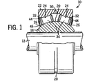
図1には、本発明を実施し、回転又は振動軸12を支持するように示されたローラベアリング装置を示している。図示された特定の実施の形態においては、ベアリング装置10は自動調心アンギュラーコンタクトベアリングである。
【0016】
ベアリング装置10は環状内側レース又はリング部材18を有し、このリング部材18を通って軸12がのびている。内側リング部材18は、内側ベアリングレース面20を形成するアーチ状外側面を備えている。内側レース面20は好ましくはほぼ球状であり、そして曲率半径Riをもっている(図2)。ミスアライメント止め及び係合シール面を形成するために必要ならば内側リング部材18の対向端部に鍔(図示していない)が設けられ得る。適当な鍔を備えたベアリング装置は特許文献2(この文献は参照文献として本明細書の一部をなす)に例示されている。
【0017】
ローラベアリング装置10はまた、内側リング部材18を包囲する環状外側レース又はリング部材22を有している。外側リング部材22は少なくとも一つの半径方向内方に向いた外側レース面を備えている。例示した構成では、外側リング部材22は、一対の軸方向に対向して傾斜したアーチ状外側レース面24を備え、各外側レース面24は内側レース面20と対向して一対の軌道空間26を形成している。外側レース面24は一般的には凸状曲率をもち、そして各々、好ましくは実質的に一定である曲率半径Roをもっている(図2)。両外側レース面24の曲率半径Roの値は好ましくは(製造誤差の範囲内で)同じであり、図示実施の形態では、曲率半径Riにほぼ等しい。
【0018】
ベアリング装置10の周期的潤滑を促進させるために、外側リング部材22の外周囲側に環状溝28が設けられ、そして環状溝28とベアリング装置10の内部との間に穴30が連通している。特許文献2に開示されたようなグリースガンのような適当な手段(図示していない)によって環状溝28内に所望の潤滑剤が注入され得る。環状溝が示されているが、周期的潤滑のための環状溝は必要ではなく、ある応用では好ましくない。本発明の範囲から逸脱せずに、必要ならばグリース内にローラを詰めるようなベアリング装置の他の潤滑手段を用いることもできる。
【0019】
ローラベアリング装置10はまた、多数のローラ34を有している。図示実施の形態において、ローラ34は、対向して軸方向に傾斜した環状列で軌道空間に配列されている。各列は、完全に相補的なローラ34を備えている(すなわち隣接したローラ間にリテーナ又は他の構造体が介在していない場合には列に最大数のローラが嵌合する)。ベアリング装置10はリテーナなしであるので、以下に詳細に説明するように、各ローラ34は対向側において隣接ローラと係合でき、しかも内側レース面20及び外側レース面24の関連した一つと係合できる。ローラ34は種々の形態を取り得るが、図示構成では、ローラは(製造誤差の範囲内で)同一であり、各ローラ34は長手方向軸線36をもち(図2)、軸線36に垂直でありかつローラ34の中間点に線38を備える平面の回りで対称である。
【0020】
図2に示すように、各ローラ34は、好ましくは一定である曲率半径Rtをもつ凹状長手方向外形のアーチ状外側面をもつ中間部分40を備えている。図示した特定の実施の形態では、曲率半径Rtは曲率半径Ri、Roの各々より大きい。各ローラ34はまた実質的に円筒状の対向した端部分42を備えている。
【0021】
ベアリング装置10はリテーナ、ガイドリング、鍔などを備えてなく、内側レース面20及び外側レース面24は、相応した軌道空間26内の各列のローラ34を保持し、そして位置決めする唯一の手段として機能する。さらに、内側レース面20は球状であり、RiはRtより小さいので、ローラ34と内側レース面20との間の摺動運動は実質的に除去され、中間線38の回りの各ローラ34の回動は、内側レース面20との干渉が最少である。従って、このような回動(すなわちスキュー)は、ローラ34と関連した外側レース面24との接触によってほぼ全体的に制御される。
【0022】
特に、無負荷状態の下では(図3)、各ローラ34と関連した外側レース面24とは実質的に点接触する。中間線38のまわりのローラ34による任意の回動(すなわちスキュー)によって、そのローラと関連した外側レース面24との間で線接触が生じ(図2参照)、さらなるスキューが抑制される。ローラスキューが続いて接触線を増大し、鼓型ローラの端部分42に達すると、これらの端部分42はさらなるスキューを抑制する。負荷状態の下では、ローラ34と関連した外側レース面24と内側レース面20との間の接触は、実質的な偏向及びローラスキューのために、ローラ34の中間点から軸方向外方へのばされる。この関係の効果は十分には理解されないが、ベアリング装置10が振動応用において用いられる場合に、ローラ34の実質的なインデックスすなわち摂動が達成されることが観察された。更に、試験では、リテーナを備えた従来技術のベアリングに対して故障するような循環で測定したところ負荷定格及び軸受寿命は実質的に延びることがわかった。これは主に、負荷を分配するローラ34の数が増大したためである。
【0023】
凹状ローラを備えた本発明の一つの特定の実施の形態では、例えば、必要ならば付加的な潤滑剤を受けるのにより少ない数のローラ34が用いられ得るが、各々直径(端面で見て)約0.4インチの全体で16個のローラ34が各列に用いられる。該実施の形態においてRtは約1.536インチであり、Ri及びRoの各々より約0.015インチである(すなわちローラと内側及び外側レース面との間に約1%の接触又は曲率差)。最適な接触値は既知ではないが、調和したローラ制御及び案内を達成するのには密な半径方向内部隙間と関連して1%の接触が有効であり、本出願人は約4%までの接触値が使用され得ると信じる。
【0024】
本出願人は、各軸方向に傾斜したローラ34と内側及び外側レース面20、24との間を0.002インチ以下の径方向内部隙間を維持することによって、外側レース面24とローラ34との共動により振動動作においてローラ34を調和して摂動させるようにローラ34のスキューを制御することを見出した。径方向内部隙間Bは図4に示され(尺度でなく)、そして内側及び外側レース面20、24の間の軌道空間26の径方向高さAとローラ半径Cとの差として定義される。ローラ34の長手方向長さに沿って半径の変化する凹状ローラ34を備えた実施の形態においては、径方向内部隙間Bは単に各ローラ34の中間点40に維持されなければならない。0.002インチの径方向内部隙間以下の誤差でベアリングを作ることは、ベアリング製造コストを高騰させる大きな製造精度を必要とし、従って従来技術からは教示されず自明ではない。本出願人の開示なしでは、調和した摂動をもたらす径方向内部隙間を減少することは既知ではない。
【0025】
当然、径方向内部隙間Bがゼロに近づくにつれて、ローラ34はレース面20、24との間に拘束でき、ベアリング装置10は動かなくなる。しかしながら、本出願人は、0.002インチ以下の非拘束径方向内部隙間Bをもつベアリング装置10において調和した摂動を首尾よく立証した。さらに、本出願人は、それぞれほぼ0.0016インチと0.0005インチの径方向内部隙間Bをもつ二つの異なるベアリング装置において調和した摂動を首尾よく立証した。さらに、本出願人は、ローラ34を拘束させない0.0005インチ以下の径方向内部隙間Bをもつベアリング装置10が調和して摂動し続けると考える。
【0026】
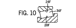
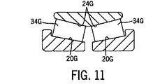
図示実施の形態では、ローラ34は鼓型のものであり、外側レース面24は凸状であり、また内側レース面は球状であるが、他の構成では、ベアリング装置10は異なる形態を採り得る。例えば、本発明によるベアリング装置は環状列の軸方向に傾斜した直線(図5〜図9に示す)又はテーパー状(図10〜図13に示す)のローラ34A−Iであることができ、また内側及び外側レース面20A−I、24A−Iは各々ローラ34A−Iを受けそしてリテーナ、ガイドリングなどを用いることなしにローラ34A−Iを適位置に保持するように軸方向に傾斜した直線状面であることができる。さらに、本発明によるベアリング装置10は、軸方向外方に傾斜したローラ(図1、図6、図8に示す)又は軸方向内方に傾斜したローラ(図7、図9、図11、図13に示す)を有することができる。さらに、図1には二つの環状列の軸方向外方に傾斜したローラ34が示されているが、ベアリング装置10は一つ以上の環状列を備えることができ、そして本発明の範囲から逸脱せずに列は軸方向内方に傾斜され得る。
【0027】
ベアリング装置10はまた、潤滑剤を収容しかつ汚染物が軌道空間26に入り込むのを阻止する手段を備える。図示構成においては、該手段は、各々ノッチ32の一つに着座した環状シールド部材44及び各環状シールド部材44に装着した環状シール部材46を備える。シール部材を備えたシールド部材44が開示されているが、これらの部材は本発明を実施するのには必要でない。
【0028】
有利には、ベアリング装置10は、ローラ34を案内又は位置決めし、そして主内側及び外側レース面20、24以外のローラスキュー(roller skewing)を制御するものを備えない(すなわち、ベアリング装置10は「リテーナなし」である)。従って、ベアリング装置10は、リテーナ、ガイドリング、鍔などに伴うコストを省く。さらに、ベアリング装置10は、有利な粒子汚染である主レース面に関連した内部コーナーの使用を避ける。ベアリング装置10はまた、性能を改善する増加した数のローラ34及び/又は付加的な潤滑剤を備え、摂動又はインデックスする能力を有する。
【0029】
以上本発明の好ましい実施の形態に関して図示し説明し考察してきたが、当業者には明らかなように、特許請求の範囲で定義した本発明の範囲から逸脱せずに種々の変形及び変更が可能である。
【図面の簡単な説明】
【図1】
軸を支持するように示されたローラベアリング装置の部分破断側面図である。
【図2】
負荷状態におけるローラを示す、図1に示すベアリング装置の一部の拡大図である。
【図3】
ローラとレース面との接触線が実質的に低減される無負荷状態におけるローラを示す、図2に示すベアリング装置部分の一部の別の拡大図である。
【図4】
図2の線4−4に沿った断面図である。
【図5】
単一環状列の直線ローラを備えた本発明と結合したベアリング装置の断面図である。
【図6】
二つの環状列の軸方向外方に傾斜した直線ローラを備えた本発明と結合したベアリング装置の断面図である。
【図7】
分割内側レースをもつ二つの環状列の軸方向内方に傾斜した直線ローラを備えた本発明と結合したベアリング装置の断面図である。
【図8】
分割外側レースをもつ二つの環状列の軸方向外方に傾斜した直線ローラを備えた本発明と結合したベアリング装置の断面図である。
【図9】
二つの環状列の軸方向内方に傾斜した直線ローラを備えた本発明と結合したベアリング装置の断面図である。
【図10】
単一環状列のテーパー状ローラを備えた本発明と結合したベアリング装置の断面図である。
【図11】
分割内側レースをもつ二つの環状列の軸方向内方に傾斜したテーパー状ローラを備えた本発明と結合したベアリング装置の断面図である。
【図12】
分割外側レースをもつ二つの環状列の軸方向外方に傾斜したテーパー状ローラを備えた本発明と結合したベアリング装置の断面図である。
【図13】
二つの環状列の軸方向内方に傾斜したテーパー状ローラを備えた本発明と結合したベアリング装置の断面図である。
【符号の説明】
10 ベアリング装置
12 軸
18 内側リング部材
20 内側レース面
22 外側リング部材
24 外側レース面
26 軌道空間
28 環状溝
30 穴
32 ノッチ
34 ローラ
44 環状シールド部材
46 環状シール部材[0001]
TECHNICAL FIELD OF THE INVENTION
The present invention relates generally to roller bearings, and more particularly, to a perturbed roller bearing without retainers for use in rotating or vibrating applications that support a rotating or vibrating axis.
[0002]
[Prior art]
Known roller bearings include various means for guiding and positioning the rollers. For example, self-aligning angular contact roller bearings are disclosed in Patent Documents 1 and 2. The roller bearings exemplified in each of these patents include an inner ring forming a substantially spherical inner race surface, a pair of outer race surfaces having a convex curvature, and a pair of oppositely inclined rows of symmetrical drums. And a roller. These roller bearings also include bearing cages or retainers to separate, guide, and position each row of rollers. An example of such a roller bearing is manufactured by Rexnord Corporation, Bearing Operation, Downers Grove, Illinois under model number DAS4-14A.
[0003]
Patent Literature 3 exemplifies a roller bearing including an asymmetric roller in an opposing row and a center guide ring. The shape and center guide ring of the rollers function to guide and position each row of rollers.
[0004]
It is also known to provide integral flanges or shoulders on the inner or outer ring of the roller bearing to guide the rollers. An example of such a roller bearing is disclosed in Patent Document 4. In this roller bearing, the inner ring is provided with integral flanges extending in the radial direction, and a roller is defined between these flanges.
[0005]
Loads acting on bearing devices such as those described above are typically carried by rollers in only a small portion of the bearing device at a time (this portion is hereinafter referred to as the "load area"). In particular, where the bearings are used in vibration applications, such as in flight control surfaces of aircraft, it is desirable that the rollers be perturbed or indexed so that they are all circulated through the load area. By circulating the rollers, the entire race surface of each roller is made available to extend the rolling contact fatigue life. Circulation of the rollers also results in redistribution of grease to improve lubrication of the bearing device, thereby reducing erosion damage and improving bearing device resistance to track corrosion. It is known to use a retainer with a skewed pocket to perturb or index the rollers in this manner. Known retainers include fingers or protrusions that are slightly angled to provide the roller with an unbalanced amount of skew that perturbs or indexes the roller during bearing oscillation.
[0006]
The disadvantages associated with the roller bearings described above are that they have bearing cages, retainers, guide rings, integral flanges, and the like. Such components are costly to manufacture and assemble as parts of the bearing device. These components will also take up space in the bearing device, otherwise this space can be used for additional rollers and / or additional lubricant.
[0007]
A fully complementary self-aligning roller bearing without a retainer guide ring is disclosed in US Pat. The bearings disclosed in U.S. Pat. No. 6,037,085 provide skew control with bearings, but roller perturbations are less harmonized than can be achieved using a retainer with a skewed picket. Accordingly, there is a need for a roller bearing with unmatched roller perturbations.
[0008]
[Patent Document 1]
US Patent No. 2,387,962 issued October 30, 1945 [Patent Document 2]
US Patent No. 2,767,037 issued October 16, 1956 [Patent Document 3]
Japanese Patent Laid-Open No. 60-188617 [Patent Document 4]
US Patent No. 3,912,346 issued October 14, 1975 [Patent Document 5]
US Patent No. 5,441,351 (assigned to the assignee of the present invention)
[0009]
[Problems to be solved by the invention]
The present invention provides an improved retainerless roller bearing device that is particularly suited for oscillating or slow rotational movement. Applicants have surprisingly found that harmonious perturbations in the bearings can reduce the inner and outer race surfaces by maintaining a radial internal clearance of 0.002 inches or less between each roller and the inner and outer race surfaces. It has been found that this can be achieved in a retainerless roller bearing device with an axially inclined roller disposed therebetween. Races with special roller clearances control the skew of the rollers to harmonize and perturb the rollers in oscillating motion.
[0010]
Applicants have observed that bearing devices embodying the present invention perturb or index to circulate the rollers through the load area. The observed roller perturbations were greater than can be achieved using a retainerless bearing as disclosed in US Pat.
[0011]
In particular, the present invention provides an inner ring member having an arcuate inner race surface, an outer ring member having an arcuate outer race surface on the inside, and a diameter of less than 0.002 inches between each roller and the race surface. A retainerless roller bearing device having a row of rollers in a raceway space defined between an inner race surface and an outer race surface with a directional internal clearance.
[0012]
[Means for Solving the Problems]
In one embodiment, a roller bearing device without a retainer includes an inner race member having a spherical inner race surface and an outer race member having a convex outer race surface opposite the inner race surface. The retainerless roller bearing arrangement also has a radial internal clearance of 0.002 inches or less between the roller and the race surface, arranged in rows in the raceway space between the inner race surface and the outer race surface. Provided with a plurality of rollers. Each roller has a concave longitudinal profile (ie, a drum-shaped profile) having a radius of curvature that is somewhat greater than the radius of curvature of each of the convex outer race surface and the spherical inner race surface. Applicants have noted that this relationship between the rollers and the race surface balances the bearing without a retainer, guide ring, collar, or other means apart from the main race surface for holding, positioning or guiding the rollers. Have been found to provide perturbed roller skew control.
[0013]
This and further objects and advantages of the present invention will become apparent from the following description. In the following detailed description, preferred embodiments of the present invention will be described with reference to the accompanying drawings. These embodiments do not represent the full scope of the invention. Rather, the invention can be used in other embodiments. Therefore, reference should be made to the appended claims for interpreting the scope of the invention.
[0014]
Before describing one embodiment of the present invention in detail, it is to be understood that the invention is not limited in its application to the details of construction and construction of the components set forth below or illustrated in the drawings. is there. The invention is capable of other embodiments and of being practiced and carried out in various ways. Further, the terms and terms used in the present specification are for explanation, not for limiting the present invention.
[0015]
BEST MODE FOR CARRYING OUT THE INVENTION
FIG. 1 shows a roller bearing device embodying the present invention and shown to support a rotating or oscillating
[0016]
The bearing
[0017]
The
[0018]
To facilitate periodic lubrication of the bearing
[0019]
The
[0020]
As shown in FIG. 2, each
[0021]
The bearing
[0022]
In particular, under no load conditions (FIG. 3), there is substantial point contact with the
[0023]
In one particular embodiment of the invention with concave rollers, for example, a smaller number of
[0024]
Applicants have determined that by maintaining a radial internal clearance of 0.002 inches or less between each axially
[0025]
Of course, as the radial internal clearance B approaches zero, the
[0026]
In the illustrated embodiment, the
[0027]
[0028]
Advantageously, the bearing
[0029]
While the preferred embodiments of the invention have been illustrated, described, and discussed above, it will be apparent to those skilled in the art that various modifications and changes can be made without departing from the scope of the invention as defined in the appended claims. It is.
[Brief description of the drawings]
FIG.
FIG. 4 is a partially broken side view of a roller bearing device shown to support a shaft.
FIG. 2
FIG. 2 is an enlarged view of a portion of the bearing device shown in FIG. 1 showing the roller in a loaded state.
FIG. 3
FIG. 3 is another enlarged view of a portion of the portion of the bearing device shown in FIG. 2 showing the roller in a no-load condition where the line of contact between the roller and the race surface is substantially reduced.
FIG. 4
FIG. 4 is a sectional view taken along lines 4-4 in FIG.
FIG. 5
FIG. 4 is a cross-sectional view of a bearing device combined with the present invention having a single annular row of linear rollers.
FIG. 6
FIG. 3 is a cross-sectional view of a bearing device combined with the present invention having two annular rows of axially outwardly inclined linear rollers.
FIG. 7
FIG. 4 is a cross-sectional view of a bearing device combined with the present invention having two annular rows of axially inwardly sloping linear rollers with split inner races.
FIG. 8
FIG. 4 is a cross-sectional view of a bearing device combined with the present invention having two annular rows of axially outwardly sloping linear rollers with split outer races.
FIG. 9
FIG. 3 is a cross-sectional view of a bearing device combined with the present invention with two annular rows of axially inwardly inclined linear rollers.
FIG. 10
FIG. 4 is a cross-sectional view of a bearing device combined with the present invention having a single annular row of tapered rollers.
FIG. 11
FIG. 4 is a cross-sectional view of a bearing device combined with the present invention having two annular rows of axially inwardly tapered rollers with split inner races.
FIG.
FIG. 4 is a cross-sectional view of a bearing device combined with the present invention having axially outwardly tapered rollers of two annular rows with split outer races.
FIG. 13
FIG. 4 is a cross-sectional view of a bearing device combined with the present invention having two annular rows of axially inwardly tapered rollers.
[Explanation of symbols]
DESCRIPTION OF
Claims (6)
内側リング部材を包囲しかつ内側レース表面と対向し内側レース面との間に軌道空間を画定する外側レース面を備えた外側リング部材と;
軌道空間内に少なくとも一つの軸方向に傾斜した列のローラを備え、前記列におけるローラの各々が前記列におけるローラの隣接したローラと係合できる複数のローラと;
を有し、前記軌道空間内の各ローラと前記リング部材との間の径方向内部隙間が0.002インチ以下であることを特徴とするリテーナなしのローラベアリング。An inner ring member with an inner race surface;
An outer ring member surrounding the inner ring member and having an outer race surface opposing the inner race surface and defining a track space between the inner race surface;
A plurality of rollers comprising at least one axially inclined row of rollers in the track space, each of the rollers in the row being able to engage an adjacent roller of the rollers in the row;
A roller bearing without a retainer, wherein a radial internal gap between each roller in the track space and the ring member is 0.002 inches or less.
Applications Claiming Priority (2)
| Application Number | Priority Date | Filing Date | Title |
|---|---|---|---|
| US09/654,628 US6394656B1 (en) | 2000-09-05 | 2000-09-05 | Retainerless precessing roller bearing |
| PCT/US2001/025360 WO2002021007A1 (en) | 2000-09-05 | 2001-08-13 | Retainerless precessing roller bearing |
Publications (1)
| Publication Number | Publication Date |
|---|---|
| JP2004508511A true JP2004508511A (en) | 2004-03-18 |
Family
ID=24625633
Family Applications (1)
| Application Number | Title | Priority Date | Filing Date |
|---|---|---|---|
| JP2002525386A Pending JP2004508511A (en) | 2000-09-05 | 2001-08-13 | Roller bearing for perturbation without retainer |
Country Status (9)
| Country | Link |
|---|---|
| US (1) | US6394656B1 (en) |
| EP (1) | EP1315914B1 (en) |
| JP (1) | JP2004508511A (en) |
| AT (1) | ATE307300T1 (en) |
| AU (1) | AU2001281266A1 (en) |
| CA (1) | CA2420474C (en) |
| DE (1) | DE60114221T2 (en) |
| ES (1) | ES2252272T3 (en) |
| WO (1) | WO2002021007A1 (en) |
Cited By (6)
| Publication number | Priority date | Publication date | Assignee | Title |
|---|---|---|---|---|
| JP2013096575A (en) * | 2011-11-02 | 2013-05-20 | Rexnord Industries Llc | Bearing assembly having floating seal |
| JP2013518230A (en) * | 2010-01-28 | 2013-05-20 | レックスノード インダストリーズ, エルエルシー | Bearing assembly with extended maintenance intervals |
| JP2014105830A (en) * | 2012-11-29 | 2014-06-09 | Jtekt Corp | Rolling bearing |
| CN104196886A (en) * | 2014-08-25 | 2014-12-10 | 浙江精久轴承有限公司 | Waist-shaped roller of linear bearing |
| JPWO2013035769A1 (en) * | 2011-09-09 | 2015-03-23 | Thk株式会社 | Exercise guidance device |
| EP3076038A1 (en) | 2015-03-31 | 2016-10-05 | Minebea Co. Ltd. | Rolling bearing with sealing arrangement |
Families Citing this family (13)
| Publication number | Priority date | Publication date | Assignee | Title |
|---|---|---|---|---|
| US7182169B2 (en) * | 2004-05-24 | 2007-02-27 | Yamaha Motor Co Ltd | Steering system for small-sized vehicle |
| JP2006179104A (en) * | 2004-12-22 | 2006-07-06 | Hitachi Global Storage Technologies Netherlands Bv | Magnetic disk drive |
| US20070086688A1 (en) * | 2005-10-17 | 2007-04-19 | Rexnord Industries, Llc | Vented bearing assembly |
| US9561845B2 (en) | 2007-12-06 | 2017-02-07 | Roller Bearing Company Of America, Inc. | Bearing installed on an aircraft structure |
| US10012265B2 (en) | 2007-12-06 | 2018-07-03 | Roller Bearing Company Of America, Inc. | Corrosion resistant bearing material |
| DE102011003513A1 (en) | 2011-02-02 | 2012-08-02 | Aktiebolaget Skf | roller bearing |
| US9227720B2 (en) | 2013-03-01 | 2016-01-05 | Roller Bearing Company Of America, Inc. | Composite annular seal assembly for bearings in aircraft |
| RU2540047C1 (en) * | 2013-07-19 | 2015-01-27 | Федеральное государственное бюджетное образовательное учреждение высшего профессионального образования "Алтайский государственный технический университет им. И.И. Ползунова" (АлтГТУ) | Spherical double-row rolling bearing |
| US10077808B2 (en) | 2013-12-18 | 2018-09-18 | Roller Bearing Company Of America, Inc. | Roller profile for hourglass roller bearings in aircraft |
| EP2927115B1 (en) * | 2014-02-28 | 2019-05-08 | Roller Bearing Company of America, Inc. | An edge flap arrangement for an aircraft wing |
| US9890814B2 (en) | 2014-06-03 | 2018-02-13 | Roller Bearing Company Of America, Inc. | Cage for hourglass roller bearings |
| US10082179B2 (en) | 2014-12-16 | 2018-09-25 | Roller Bearing Company Of America, Inc. | Seal for self aligning roller bearing |
| CN113175478A (en) * | 2021-03-25 | 2021-07-27 | 山东凯美瑞轴承科技有限公司 | Concave spherical surface cylindrical roller bearing |
Citations (4)
| Publication number | Priority date | Publication date | Assignee | Title |
|---|---|---|---|---|
| JPH0439329A (en) * | 1990-06-05 | 1992-02-10 | Showa Shell Sekiyu Kk | Aromatic copolyamide and production thereof |
| JPH07119739A (en) * | 1993-10-26 | 1995-05-09 | Rexnord Corp | Total self-aligning type roller bearing |
| JPH07293558A (en) * | 1994-04-22 | 1995-11-07 | Nippon Seiko Kk | Wholly-tapered roller bearing |
| JPH07293557A (en) * | 1994-04-27 | 1995-11-07 | Nippon Seiko Kk | Rotation support device for planetary gear |
Family Cites Families (33)
| Publication number | Priority date | Publication date | Assignee | Title |
|---|---|---|---|---|
| US1914548A (en) | 1931-07-29 | 1933-06-20 | Wingquist Sven Gustaf | Double-row roller bearing |
| DE649528C (en) | 1935-01-26 | 1937-08-26 | Skf Svenska Kullagerfab Ab | Roller cage made of sheet metal for double-row roller bearings |
| US2387962A (en) | 1942-09-28 | 1945-10-30 | Shafer Bearing Corp | Antifriction bearing |
| US2586406A (en) | 1946-06-14 | 1952-02-19 | Wallgren August Gunn Ferdinand | Double row roller bearing |
| US2767037A (en) | 1954-02-09 | 1956-10-16 | Chain Belt Co | Seal for rotary anti-friction bearings |
| GB747314A (en) | 1954-05-20 | 1956-04-04 | British Timken Ltd | Improvements relating to tapered roller bearings |
| GB929146A (en) | 1960-03-05 | 1963-06-19 | Skf Svenska Kullagerfab Ab | Improvements in or relating to spherical roller bearings |
| US3046066A (en) | 1960-12-23 | 1962-07-24 | Bantam Bearing Division | Spherical roller bearing with bipartite retainer |
| US3912346A (en) | 1969-02-06 | 1975-10-14 | Poznanska Fabryka Lozysk Toczn | Double-row self-aligning bearing |
| US3930693A (en) | 1970-05-22 | 1976-01-06 | The Torrington Company | Full complement bearing having preloaded hollow rollers |
| US3953142A (en) | 1972-06-21 | 1976-04-27 | Fmc Corporation | Wedge mounted machine element |
| US3963285A (en) | 1973-10-09 | 1976-06-15 | Skf Industries, Inc. | Cage control of skew angle in roller bearings |
| US3910656A (en) * | 1973-11-12 | 1975-10-07 | Fmc Corp | Spherical roller bearing for heavy loads |
| AT336059B (en) | 1974-01-10 | 1977-04-12 | Voest Ag | BEARING FOR ACCOMPANYING ANGULAR DISPLACEMENT ON TORQUE TRANSMITTING PINS |
| US3934957A (en) | 1974-02-13 | 1976-01-27 | Fmc Corporation | Preloaded double row spherical roller bearing |
| US3938865A (en) | 1974-04-01 | 1976-02-17 | Rouverol William S | Cageless roller bearing |
| DE2651827A1 (en) | 1976-11-13 | 1978-05-18 | Kugelfischer G Schaefer & Co | FULL-ROLLED OR FULL-SPHERICAL ROLLER BEARING |
| US4120542A (en) | 1976-12-15 | 1978-10-17 | The Torrington Company | Cageless thrust bearing with unguided rollers |
| US4139317A (en) | 1977-10-03 | 1979-02-13 | Fmc Corporation | Bearing locking assembly |
| US4557613A (en) | 1978-09-01 | 1985-12-10 | Skf Industries, Inc. | Spherical roller bearing having reciprocal crowning for skew control |
| US4492415A (en) | 1982-03-03 | 1985-01-08 | Skf Industries, Inc. | Unitary full complement bearing components containing rolling elements in a self-supporting lubricating matrix |
| JPS60188617A (en) | 1984-03-07 | 1985-09-26 | Kawasaki Steel Corp | Roller bearing capable of standing both radial and thrust loads |
| SE449908B (en) | 1984-09-26 | 1987-05-25 | Skf Ab | ROLLER BEARINGS WHERE THE ROLLERS AND ROPES ARE CROSSED LENGTH CROSS PROFILES |
| DE3504059A1 (en) | 1985-02-07 | 1986-08-07 | FAG Kugelfischer Georg Schäfer KGaA, 8720 Schweinfurt | KAEFIG FOR BORDERLESS ROLLER BEARINGS |
| DE3537243A1 (en) | 1985-10-19 | 1987-04-23 | Kugelfischer G Schaefer & Co | Two-row self-aligning roller bearing |
| SU1521949A1 (en) | 1986-09-10 | 1989-11-15 | Минский Филиал Научно-Производственного Объединения "Всесоюзный Научно-Исследовательский Конструкторско-Технологический Институт Подшипниковой Промышленности" | Spherical roller bearing |
| US5037214A (en) | 1988-02-29 | 1991-08-06 | The Timken Company | Double row tapered roller bearing assembly |
| DE3912449A1 (en) | 1989-04-15 | 1990-10-18 | Skf Gmbh | PRELOADED DOUBLE-ROW BEARING BEARING AND METHOD FOR ITS ASSEMBLY |
| US5000587A (en) | 1990-03-02 | 1991-03-19 | Link-Belt Bearings Division Of Rexnord Corporation | Bearing assembly and auxiliary bearing seal |
| US5269609A (en) | 1991-08-05 | 1993-12-14 | The Torrington Company | Pin type bearing retainer |
| US5437209A (en) * | 1993-09-30 | 1995-08-01 | The Torrington Company | Rocker arm assembly |
| US5413416A (en) | 1993-12-03 | 1995-05-09 | Rexnord Corporation | Roller guide member for full complement roller bearing |
| SE509965C2 (en) * | 1996-11-21 | 1999-03-29 | Skf Ab | Roll bearings with means for giving the rollers a positive angle of rotation |
-
2000
- 2000-09-05 US US09/654,628 patent/US6394656B1/en not_active Expired - Lifetime
-
2001
- 2001-08-13 EP EP01959742A patent/EP1315914B1/en not_active Expired - Lifetime
- 2001-08-13 CA CA002420474A patent/CA2420474C/en not_active Expired - Lifetime
- 2001-08-13 WO PCT/US2001/025360 patent/WO2002021007A1/en active IP Right Grant
- 2001-08-13 JP JP2002525386A patent/JP2004508511A/en active Pending
- 2001-08-13 DE DE60114221T patent/DE60114221T2/en not_active Expired - Lifetime
- 2001-08-13 AU AU2001281266A patent/AU2001281266A1/en not_active Abandoned
- 2001-08-13 AT AT01959742T patent/ATE307300T1/en not_active IP Right Cessation
- 2001-08-13 ES ES01959742T patent/ES2252272T3/en not_active Expired - Lifetime
Patent Citations (4)
| Publication number | Priority date | Publication date | Assignee | Title |
|---|---|---|---|---|
| JPH0439329A (en) * | 1990-06-05 | 1992-02-10 | Showa Shell Sekiyu Kk | Aromatic copolyamide and production thereof |
| JPH07119739A (en) * | 1993-10-26 | 1995-05-09 | Rexnord Corp | Total self-aligning type roller bearing |
| JPH07293558A (en) * | 1994-04-22 | 1995-11-07 | Nippon Seiko Kk | Wholly-tapered roller bearing |
| JPH07293557A (en) * | 1994-04-27 | 1995-11-07 | Nippon Seiko Kk | Rotation support device for planetary gear |
Cited By (8)
| Publication number | Priority date | Publication date | Assignee | Title |
|---|---|---|---|---|
| JP2013518230A (en) * | 2010-01-28 | 2013-05-20 | レックスノード インダストリーズ, エルエルシー | Bearing assembly with extended maintenance intervals |
| JPWO2013035769A1 (en) * | 2011-09-09 | 2015-03-23 | Thk株式会社 | Exercise guidance device |
| JP2013096575A (en) * | 2011-11-02 | 2013-05-20 | Rexnord Industries Llc | Bearing assembly having floating seal |
| JP2014105830A (en) * | 2012-11-29 | 2014-06-09 | Jtekt Corp | Rolling bearing |
| CN104196886A (en) * | 2014-08-25 | 2014-12-10 | 浙江精久轴承有限公司 | Waist-shaped roller of linear bearing |
| EP3076038A1 (en) | 2015-03-31 | 2016-10-05 | Minebea Co. Ltd. | Rolling bearing with sealing arrangement |
| JP2016191411A (en) * | 2015-03-31 | 2016-11-10 | ミネベア株式会社 | Rolling bearing |
| US9638254B2 (en) | 2015-03-31 | 2017-05-02 | Minebea Co., Ltd | Rolling bearing |
Also Published As
| Publication number | Publication date |
|---|---|
| EP1315914B1 (en) | 2005-10-19 |
| DE60114221D1 (en) | 2006-03-02 |
| ES2252272T3 (en) | 2006-05-16 |
| CA2420474A1 (en) | 2002-03-14 |
| EP1315914A1 (en) | 2003-06-04 |
| US6394656B1 (en) | 2002-05-28 |
| AU2001281266A1 (en) | 2002-03-22 |
| CA2420474C (en) | 2009-08-11 |
| ATE307300T1 (en) | 2005-11-15 |
| WO2002021007A1 (en) | 2002-03-14 |
| DE60114221T2 (en) | 2006-07-27 |
Similar Documents
| Publication | Publication Date | Title |
|---|---|---|
| JP2004508511A (en) | Roller bearing for perturbation without retainer | |
| US5441351A (en) | Full complement self-aligning roller bearing | |
| US4906112A (en) | Multirow ball or roller bearing or combined ball/roller bearing | |
| US9746027B2 (en) | Auxiliary bearing of the ball bearing type for a magnetically suspended rotor system | |
| KR101389164B1 (en) | Spacer for a radial needle roller bearing | |
| WO2012099120A1 (en) | Roller bearing | |
| US20120281940A1 (en) | Ball bearing cage | |
| US6367982B1 (en) | Cylindrical roller bearing | |
| US5829890A (en) | Bearing assembly axial load application | |
| US1973994A (en) | Antifriction bearing | |
| JP6544000B2 (en) | Self-aligning roller bearing | |
| WO2020196172A1 (en) | Self-aligning roller bearing | |
| JP2004144183A (en) | Radial rolling bearing | |
| JP2006112555A (en) | Roller bearing with aligning ring | |
| KR20170093707A (en) | Roller bearing | |
| WO2017043425A1 (en) | Rolling bearing | |
| US11725692B2 (en) | Cage segment and associated rolling bearing | |
| US20220235821A1 (en) | Cage segment and associated rolling bearing | |
| JP2010025191A (en) | Self-aligning roller bearing | |
| JP2019173860A (en) | Double row roller bearing | |
| US20230407910A1 (en) | Axial bearing assembly with cage to accommodate radial misalignment condition | |
| WO2017043414A1 (en) | Roller bearing | |
| US3411839A (en) | Quill type roller bearing | |
| WO2023112625A1 (en) | Rolling bearing | |
| WO2024053142A1 (en) | Roller bearing |
Legal Events
| Date | Code | Title | Description |
|---|---|---|---|
| A621 | Written request for application examination |
Free format text: JAPANESE INTERMEDIATE CODE: A621 Effective date: 20080617 |
|
| A131 | Notification of reasons for refusal |
Free format text: JAPANESE INTERMEDIATE CODE: A131 Effective date: 20101221 |
|
| A521 | Request for written amendment filed |
Free format text: JAPANESE INTERMEDIATE CODE: A523 Effective date: 20110318 |
|
| A131 | Notification of reasons for refusal |
Free format text: JAPANESE INTERMEDIATE CODE: A131 Effective date: 20110607 |
|
| A02 | Decision of refusal |
Free format text: JAPANESE INTERMEDIATE CODE: A02 Effective date: 20111108 |