JP2004507667A - Method for feedback control of rotational speed of drive device - Google Patents
Method for feedback control of rotational speed of drive device Download PDFInfo
- Publication number
- JP2004507667A JP2004507667A JP2002523509A JP2002523509A JP2004507667A JP 2004507667 A JP2004507667 A JP 2004507667A JP 2002523509 A JP2002523509 A JP 2002523509A JP 2002523509 A JP2002523509 A JP 2002523509A JP 2004507667 A JP2004507667 A JP 2004507667A
- Authority
- JP
- Japan
- Prior art keywords
- drive
- rotational speed
- loop control
- closed
- power
- Prior art date
- Legal status (The legal status is an assumption and is not a legal conclusion. Google has not performed a legal analysis and makes no representation as to the accuracy of the status listed.)
- Pending
Links
Images


Classifications
-
- B—PERFORMING OPERATIONS; TRANSPORTING
- B60—VEHICLES IN GENERAL
- B60W—CONJOINT CONTROL OF VEHICLE SUB-UNITS OF DIFFERENT TYPE OR DIFFERENT FUNCTION; CONTROL SYSTEMS SPECIALLY ADAPTED FOR HYBRID VEHICLES; ROAD VEHICLE DRIVE CONTROL SYSTEMS FOR PURPOSES NOT RELATED TO THE CONTROL OF A PARTICULAR SUB-UNIT
- B60W10/00—Conjoint control of vehicle sub-units of different type or different function
- B60W10/04—Conjoint control of vehicle sub-units of different type or different function including control of propulsion units
- B60W10/06—Conjoint control of vehicle sub-units of different type or different function including control of propulsion units including control of combustion engines
-
- B—PERFORMING OPERATIONS; TRANSPORTING
- B60—VEHICLES IN GENERAL
- B60W—CONJOINT CONTROL OF VEHICLE SUB-UNITS OF DIFFERENT TYPE OR DIFFERENT FUNCTION; CONTROL SYSTEMS SPECIALLY ADAPTED FOR HYBRID VEHICLES; ROAD VEHICLE DRIVE CONTROL SYSTEMS FOR PURPOSES NOT RELATED TO THE CONTROL OF A PARTICULAR SUB-UNIT
- B60W10/00—Conjoint control of vehicle sub-units of different type or different function
- B60W10/02—Conjoint control of vehicle sub-units of different type or different function including control of driveline clutches
-
- B—PERFORMING OPERATIONS; TRANSPORTING
- B60—VEHICLES IN GENERAL
- B60W—CONJOINT CONTROL OF VEHICLE SUB-UNITS OF DIFFERENT TYPE OR DIFFERENT FUNCTION; CONTROL SYSTEMS SPECIALLY ADAPTED FOR HYBRID VEHICLES; ROAD VEHICLE DRIVE CONTROL SYSTEMS FOR PURPOSES NOT RELATED TO THE CONTROL OF A PARTICULAR SUB-UNIT
- B60W30/00—Purposes of road vehicle drive control systems not related to the control of a particular sub-unit, e.g. of systems using conjoint control of vehicle sub-units, or advanced driver assistance systems for ensuring comfort, stability and safety or drive control systems for propelling or retarding the vehicle
- B60W30/18—Propelling the vehicle
- B60W30/184—Preventing damage resulting from overload or excessive wear of the driveline
-
- F—MECHANICAL ENGINEERING; LIGHTING; HEATING; WEAPONS; BLASTING
- F16—ENGINEERING ELEMENTS AND UNITS; GENERAL MEASURES FOR PRODUCING AND MAINTAINING EFFECTIVE FUNCTIONING OF MACHINES OR INSTALLATIONS; THERMAL INSULATION IN GENERAL
- F16D—COUPLINGS FOR TRANSMITTING ROTATION; CLUTCHES; BRAKES
- F16D33/00—Rotary fluid couplings or clutches of the hydrokinetic type
- F16D33/06—Rotary fluid couplings or clutches of the hydrokinetic type controlled by changing the amount of liquid in the working circuit
- F16D33/16—Rotary fluid couplings or clutches of the hydrokinetic type controlled by changing the amount of liquid in the working circuit by means arranged externally of the coupling or clutch
-
- F—MECHANICAL ENGINEERING; LIGHTING; HEATING; WEAPONS; BLASTING
- F16—ENGINEERING ELEMENTS AND UNITS; GENERAL MEASURES FOR PRODUCING AND MAINTAINING EFFECTIVE FUNCTIONING OF MACHINES OR INSTALLATIONS; THERMAL INSULATION IN GENERAL
- F16H—GEARING
- F16H61/00—Control functions within control units of change-speed- or reversing-gearings for conveying rotary motion ; Control of exclusively fluid gearing, friction gearing, gearings with endless flexible members or other particular types of gearing
- F16H61/38—Control of exclusively fluid gearing
- F16H61/48—Control of exclusively fluid gearing hydrodynamic
- F16H61/64—Control of exclusively fluid gearing hydrodynamic controlled by changing the amount of liquid in the working circuit
-
- B—PERFORMING OPERATIONS; TRANSPORTING
- B60—VEHICLES IN GENERAL
- B60W—CONJOINT CONTROL OF VEHICLE SUB-UNITS OF DIFFERENT TYPE OR DIFFERENT FUNCTION; CONTROL SYSTEMS SPECIALLY ADAPTED FOR HYBRID VEHICLES; ROAD VEHICLE DRIVE CONTROL SYSTEMS FOR PURPOSES NOT RELATED TO THE CONTROL OF A PARTICULAR SUB-UNIT
- B60W2710/00—Output or target parameters relating to a particular sub-units
- B60W2710/06—Combustion engines, Gas turbines
- B60W2710/0644—Engine speed
-
- F—MECHANICAL ENGINEERING; LIGHTING; HEATING; WEAPONS; BLASTING
- F16—ENGINEERING ELEMENTS AND UNITS; GENERAL MEASURES FOR PRODUCING AND MAINTAINING EFFECTIVE FUNCTIONING OF MACHINES OR INSTALLATIONS; THERMAL INSULATION IN GENERAL
- F16H—GEARING
- F16H2312/00—Driving activities
- F16H2312/02—Driving off
Abstract
Description
【0001】
【発明の属する技術分野】
本発明は、駆動装置の回転数をフィードバック制御するための方法、より詳細には、請求項1の前提部分おいて書き部に記載の特徴を用いた方法に関し、さらには、この方法の適用対象に関する。
【0002】
【従来の技術】
少なくとも一つの駆動装置と、この駆動装置に少なくとも間接的に連結可能な立ち上げ要素(Anfahrelement)とを有しているパワー・ライン、特に乗り物用のパワー・ライン内で回転数をフィードバック制御する方法、それも、立ち上げ過程(Anfahrvorgang)の間に回転数をフィードバック制御する方法は、フィードバック制御工程を開始させる量、つまり調整部の入力値に関する、また、制御量の他の量に対する依存性に関する、さらに、操作量に関する数々の異なる実施形態において知られている。内燃機関、特にオットーエンジンないしディーゼルエンジンと、この内燃機関に連結可能な機械的ないし流体力学的な立ち上げ要素とを有している乗り物のパワー・ライン内では、駆動装置の回転数をフィードバック制御するために、操作量として、絞り弁やノズルといったパワー操作部の調整を間接的にしろ特徴付ける量が生成され、そして、この量によって絞り弁やノズルといった調節装置が制御されることが知られている。これについては、Bosch社の「Dieseleinspritztechnik」、VDI−Verlag 1993, S. 162ff. を代わりに参照されたい。ここで、立ち上げ過程とは、パワー・ラインが運転し続ける期間のことであって、スタートから、つまり駆動装置の立ち上げから、流体力学的な立ち上げ要素により調整されながらさらに高いギヤ段に変るまでの立ち上げユニットの立ち上がりによって特徴付けられる期間のことを言う。
【0003】
乗り物内の立ち上げ要素として、流体力学的な継手を用いる場合には、斯かる継手は、立ち上げ過程の間に、駆動装置の回転数に従って、あるいはこれに遅れを持たせて、充填が自動的に行なわれ得るようにして形成されている。しかしながら、これにより生じる伝達比は、継手の性能曲線によって特徴付けられていて、高い回転数においてのみ高いモーメントが伝達可能というようにタイプが決まってしまうことが分かっている。このことはしかし、駆動装置を内燃機関として構成する場合には、モータ性能曲線図において消費が最適化される領域、したがって、有害物質の少ない運転の様態が得られないことに加えて、より高いモーメントを伝達するためには、駆動装置によるそれ相応の高いパワーが常に必要であることを意味している。
【0004】
【発明が解決しようとする課題】
本発明は、駆動装置の回転数をフィードバック制御するための方法を開発し、これにより、上記の問題が回避され、さらに、必要があれば、エネルギー財政面で最適な領域、とりわけ、内燃機関とされた駆動装置を用いる場合には、消費が最適化された領域が、駆動装置の性能曲線図において立ち上げ過程の間に得られることができるようにすることを目的とする。本発明による解決手段は、このとき、開ループ制御技術的ならびに閉ループ制御技術的にも、また構成的にも手間が少ない点に特徴を有するものでなければならない。
【0005】
【課題を解決するための手段】
本発明による解決手段は、請求項1の特徴部によって表されている。好ましい実施形態は、下位請求項に記述されている。好ましい適用対象は、請求項12から請求項15に記載されている。開ループ制御装置、及び/又は閉ループ制御装置は、請求項16に記載されている。
【0006】
回転が拘束された状態で駆動装置に連結できる立ち上げ要素を流体力学的継手の形態として少なくとも一つ有しているパワー・トレーン内で、上記駆動装置の回転数をフィードバック制御するための方法は、本発明により、上記駆動装置の回転数が、流体力学的継手により受容できる、回転数とトルクの関数としてのパワーに従って調節されることを特徴とする。これは、少なくとも間接的に駆動装置の回転数を特徴付ける量と、少なくとも間接的にこの駆動装置の回転数を特徴付ける量の目標値との間に制御偏差が生じた場合に、
a)開ループ制御、及び/又は
b)閉ループ制御、による所定の回転数での流体力学的継手のパワー受容の制御、特にモーメントの受容の制御、
によって駆動装置の回転数を変更することを意味する。
ここで、「少なくとも間接的に駆動装置の回転数を特徴付ける量」とは、駆動装置の回転数に比例関係にある量であって、この量で駆動装置の回転数が算出、特に計算されるか導出されることが可能か、もしくは、駆動装置の回転数が直接算出されるような量である。
【0007】
本発明による解決手段によれば、駆動装置の性能曲線図の中の、エネルギー的に最適となる動作点、駆動装置が内燃機関とされているような実施形態の場合には、燃費が最適となる動作点の自由な制御が可能となることに加えて、まだ低い回転数のときでも高いモーメントの伝達が可能で、しかも、これに対して、駆動装置により供給可能とされる、調達されるべき必要なパワーを低く保てるという利点が得られる。
【0008】
本発明のさらなる観点において、流体力学的継手のパワーの受け取りの開ループ制御、及び/又は閉ループ制御は、流体力学的継手の充填度の開ループ制御、及び/又は閉ループ制御によって行なわれる。このとき、最も簡単な場合においては、一つの開ループ制御が行なわれるようにする。充填度の制御は、このとき、好ましくは、静止している媒体に作用圧力を加えることによって、とりわけ、作動媒体供給装置における作動媒体貯蔵装置の枠内に現れている作動媒体の液面に作用圧力を加えることによって行なわれる。この場合、作動室内に存在する作動媒体の一部が、流体力学的継手の動作中に、少なくとも一つのポンプ羽根板およびタービン羽根板の間のトーラス形の作動室からの出口と、少なくとも一つのこのトーラス形の作動室への入口との間にある閉循環回路の中に導かれる。このとき、上記入口は、周囲に対して漏れの無いように密閉されている作動媒体貯蔵ユニットに連結されている。制御偏差が生じた場合には、作動媒体貯蔵ユニット内に溜め置かれている媒体への作用圧力を生成するための操作量が生成され、かつ、その調節装置が制御される。作動媒体貯蔵装置内の作動媒体の液面と巡回している閉循環回路との間の圧力均衡が調節されるまで、充填したり空にしたりすることが行なわれる。
【0009】
本発明のさらなる観点において、駆動装置の性能曲線図中の個々の点を自由に制御できることを用いながら、充填度を制御することによって、必要なら付加的なパラメタをも考慮に入れて、さらなる追加の機能を実現することができる。これには、以下のもの、
a)モータと作業装置との間の完全な切り離しの実現、
b)モータと作業装置との間のしっかりした堅固な連結の実現、
c)滑りを調節することを通じて制振を行なう機能、
が含まれる。
【0010】
パワー・ラインにおける立ち上げ過程の間ずっと、つまり、流体力学的継手が作動している期間の回転数のフィードバック制御のオプションが設けられていることが好ましい。
【0011】
さらなる発展態様において、本発明に係る方法は、駆動装置のパワー供給に対する閉ループ制御の制御対象を構成する一部である。これは、駆動装置により供給されるパワーの外部フィードバック制御を、駆動装置を直接操作することなしに、とりわけ、パワー操作部を制御する必要なしに容易に実現するのに有効で、これにより、開ループ制御技術的ならびに閉ループ制御技術的な手間が低減されることになる。
【0012】
このさらなる発展態様に基づいた好ましい実施形態において、本方法は、作業装置の維持機能に関して、一定で時間に依存しない維持モーメントを調節するための制御対象の一部を成す。この特殊な制御の課題によって、例えば、乗り物を斜面で維持する間等、従来のブレーキ装置の負担が軽減される。
【0013】
他の可能な構成は、駆動装置の回転数フィードバック制御は、一定で時間にもモータの回転数にも依存しない従動部回転数、すなわち、例えば作業装置の従動部における回転数を調節するための閉ループ制御に統合されるというものである。
【0014】
この方法の主たる長所は、さらに、個々の開ループ制御および閉ループ制御の課題の実現のために、フィードバック制御工程に関して少なくとも以下に挙げられる量、すなわち、
− 駆動装置の実際の回転数瞬時値と、
− 流体継手の従動部側での実際の回転数瞬時値と、
− 従動部の回転方向と、
− 所望される調節されるべき駆動装置の回転数を少なくとも間接的に特徴付けている量と、
− パワー・トレーンの個々の構成要素の働き方を記述するための随意の内部状態量と、
を単に考慮するだけでよいという点にある。
【0015】
相応の検出装置を用意するための手間も、このとき同じように少なくて済むか、あるいは、パワー・ラインにもともと設けられている検出装置に限られるものである。
【0016】
本発明に係る回転数をフィードバック制御する解決手段、とりわけ、充填度に従って駆動装置の回転数を調節する解決手段は、立ち上げ要素としての流体力学的継手を有するパワー・ラインの具体的な構成に制限されない。ここで、駆動装置は、例えば、内燃機関もしくは電気モータとして形成されていてもよい。本発明は、固定された設備や、あるいは、好ましくは乗り物といった動く装置に用いることができる。
【0017】
【発明の実施の形態】
以下、本発明による解決手段を図面に基づき説明する。
【0018】
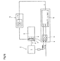
図1aには、駆動装置1の回転数をパワー・トレーン2内において立ち上げ過程の間にフィードバック制御するための本発明に係る方法の基本的な原理が、ブロック図により概略的に示されている。ここで、パワー・トレーン2は、少なくとも間接的に駆動装置1に連結可能な立ち上げ要素3を備えており、この立ち上げ要素3は、流体力学的継手4として形成され、この流体力学的継手は、ポンプ羽根板として機能する少なくとも一つの一次ベーン5と、タービン羽根板として機能する少なくとも一つの二次ベーン6とを有し、これらの一次ベーン5と二次ベーン6とが一緒になって少なくとも一つの作動室7を形成している。上記駆動装置1は、本発明に係る方法を、乗り物に好適に利用する場合には、内燃機関として構成されていることが好ましいが、電気モータとして形成されていてもよい。上記立ち上げ要素は、トランスミッションユニット8の中に統合されていることが好ましい。
【0019】
本発明によれば、モータトルクMの関数としての駆動装置1の回転数のフィードバック制御が、流体力学的継手4を介して受容できる、得られうるモーメントM受に従って行なわれる。すなわち、流体力学的継手4により受容可能なパワーP受、とりわけ受容可能なモーメントの大きさによって、つまり、概ね駆動装置1により供給可能なパワーP与 Mに相当、もしくは、補助ユニット(Nebenaggregat)や追加ユニット(Zusatzaggregat)の駆動に要するパワーの分だけ減らされたパワーに相当する大きさによって、伝達可能なモーメントMが、生じている個々のベーンの回転数比nT/nPと出力価との間の、継手の所定の充填度FGに対応させられた特徴的な関係に基づいて決定される。この受容可能なパワーによって、かくして、ポンプ羽根板の回転数nPと、ゆえに、この回転数に対応、ないし、少なくともこの回転数に比例した駆動装置1の回転数nMが与えられる。
【0020】
このとき、流体力学的継手4により受容可能なパワーP受に従って駆動装置1の所定の回転数nM 目標を制御するため、図1a、ならびに、そのシグナルフロー図に相当する図1bに示すように、流体力学的継手4の受容するパワーの開ループ制御、ないしは閉ループ制御、つまり、図1cにおけるシグナルフロー図のように、受容できるパワーP受の閉ループ制御を用いて行われる。
【0021】
受容可能なパワーP受の大きさは、流体力学的継手4の充填度FGの関数である。そのため、この充填度FGが制御される。
【0022】
この目的のため、装置に関して言えば、上記駆動装置1に対して、少なくとも開ループ制御及び/又は閉ループ制御装置10を備えた開ループ制御及び/又は閉ループ制御設備9が設けられ、この開ループ制御及び/又は閉ループ制御設備は、少なくとも比較装置11を備え、この比較装置11内において、少なくとも間接的に駆動装置の回転数nMを記述する或る量、特に好適には回転数そのものに対する目標値nM 目標と、少なくとも間接的に駆動装置の回転数を特徴付ける或る量、特に好適にはその時の実際の回転数そのものに対する瞬時値nM 瞬時とが比較される。この駆動装置1の回転数目標値nM 目標と回転数瞬時値nM 瞬時との間の制御偏差ΔnMから、流体力学的継手4、特に一次ベーン5により受容可能なパワーP受を開ループ制御するための操作量が生成される。図1cに示されるような、受容可能なパワーP受に対する閉ループ制御を行う好ましい場合には、操作量から目標量P受目標が生成され、実際の瞬時量P受瞬時と続けて比較される。このとき、受容可能なパワーの瞬時値P受瞬時の検出は、最も簡単な場合には、少なくとも間接的にパワーを記述するモーメント〔M瞬時(mist)〕と回転数〔M瞬時(mist)〕とを検出することによって行なわれるが、そのためには、相応の検出装置が設けられる必要があろう。この制御偏差ΔP受によって、操作量yの相応の変更がもたらされる。この操作量yに効力を持たせるため、流体力学的継手4には、パワー受容に変更、又は作用を加えるための装置12が設けられている。この装置は、ループに関しては、回転数フィードバック制御の制御対象13の中に統合されている。このとき、受容するパワーに変更、及び/又は作用を加えるための装置12は、立ち上げ過程の間に充填度を変更するための手段14を備えている。その際、静止している媒体上に外部圧力を加えて、閉じて巡回する循環回路と、静止している媒体との間に圧力均衡を生じさせる充填度制御によって充填度の変更が行われることが好ましい。この閉じて巡回する循環回路は、圧力封止されて形成、つまり、流体力学的継手の作動室からの流出室と流入室、ならびに、これらの間の導管の接合が圧力媒体に対して漏れの無いように形成されている。作用圧力pBとも称されるこの圧力は、例えば、充填度を変更するための手段14の構成部とされている圧力調節バルブ15によって生成される。
【0023】
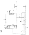
静止している媒体上に外部圧力を加える原理は、図2に、流体力学的継手4、ならびに、この流体力学的継手に対して設けられた作動媒体供給システム18の概略図によって再び詳細に示されている。ここで、流体力学的継手内のトーラス形の作動室5の中に存在している作動媒体の一部が、閉じた循環回路19内を巡回する。ここで、この閉じた循環回路19は、冷却物質循環回路として構成されていて、つまり、流体力学的継手4が動作している間、作動媒体が作動室7より、特に、この作動室7からの出口21より決まった量引き出され、少なくとも入口21を介して作動室7内へ導かれる。そのために、導管システム22が設けられている。この導管システム内には、例えば、熱交換器といったような熱を取り去るための手段23が設けられている。作動媒体を閉じた循環回路19の中で作動室7から作動室7内へと導くことは、主に作動媒体の冷却に有用で、特に、連続的な冷却作動媒体流を生成するのに有用である。作動媒体供給システム18は、例えば、容器やタンク内の作動媒体溜めといった形態の、圧力封止されて構成された作動媒体貯蔵装置24を備え、この貯蔵装置が、少なくとも一つの連結路25を介して、上記入口21の領域で、閉じた循環回路19に連結可能とされている。作動媒体貯蔵装置24は、このとき、現れる作動媒体の液面26が、好ましくはトーラス形の作動室7の下方に配置されるように設けられている。この作動媒体の液面26上には、充填度FGを変更するために、作用圧力pBが加えられ、このとき、この作用圧力が、閉じられた作用媒体溜め上に作用を及ぼしながら、熱交換器の下流側の入口21の領域における圧力が或る圧力平衡に達するまで、連結路25を介してトーラス形の作動室内の作動循環路の中に作動媒体を入れる。
【0024】
図1bには、受容可能なパワーP受を開ループ制御する場合の、回転数フィードバック制御の全ループ27の中における各要素の相互作用がシグナルフロー図によって示されている。調節装置16は、機能的には開ループ制御/閉ループ制御装置10に相当している。ここで、制御対象13は、ループの一部分であって、まさにパワー・ライン2における作用されるべき部分となっている。このとき、上記調節装置16を用いて、圧力調節弁15より形成された操作部17を介して、制御対象13に作用が及ぼされる。さらなる伝達要素として動作するのは、密閉構成された作動媒体貯蔵装置24および流体力学的継手4である。これらの要素により受容可能な、充填度FGの関数としてのパワーP受は、その際、所定のモーメントMKPおよび所定の回転数nKPに対応し、こうして、駆動装置1により供給可能なパワーP与 Mが決定可能となり、さらにこのとき、充填度FGに対応して得られるモーメントに従って、駆動装置1の回転数nMが決定可能となる。
【0025】
図1cには、受容可能なパワーP受を閉ループ制御する場合の、回転数フィードバック制御の全ループ28の中における各要素の相互作用がシグナルフロー図によって示されている。受容可能なパワーP受の閉ループ制御のためのループは、ここでは符号29によって示されている。その他に関しては、制御対象13は、図1bに示されたものに対応しているため、同じ要素に同じ符号が付されている。
【0026】
本発明の解決手段により、駆動装置1の回転数nMを調節することができ、これにより、立ち上げ過程に関する駆動装置の最適な振る舞いが達成可能になる。このとき、駆動装置1の性能曲線図中の個々の動作点のそれぞれが、単独に、あるいは変動無く動かされ、つまり調節されることが可能となる。これは、流体力学的継手により受容可能なパワーの開ループ制御もしくは閉ループ制御に依って行なわれる。
【0027】
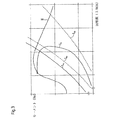
回転数フィードバック制御のための主な基準は、特に乗り物用の構成の場合に、排気最適化運転の内燃機関として駆動装置が形成されているときには、駆動装置1の無負荷でのランナップ(Hochlauf)である。立ち上げ要素、特に流体力学的継手によるパワーの受容は、これらに依存して、少なくとも間接的にこれらに従動側で接続される作業装置には依存しない。そのため、駆動装置1と従動部との間にこういった要素を挿入する際に考慮する必要があるのは、駆動装置1と流体力学的継手との間のどの負荷状態に対しても、トルクと回転数とに関する平衡状態も得られなければならないということである。駆動装置により供給されるパワーは、立ち上げ過程の間、立ち上げ要素の下流側に設けられた変速機ユニットや、したがってまた、流体力学的な要素にとって、完全に自由に使用できる状態に殆ど無い。立ち上げ要素の上流側に設けられている、例えば、ベンチレータ、発電機、ポンプ等の補助装置のためのパワーは、このとき、自由に使用できる駆動パワーから取り出されなければならない。この場合、低い回転数での立ち上げ過程の間に、駆動装置をできるだけ消費が最適化された領域で稼動させるために、まだ非常に低い回転数のときでもできるだけ大きなモーメントが伝達される必要がある。このような動作の仕方は、意図的に充填度を変えることによって達成することができる。流体力学的継手を介して受容可能なパワーによって、このとき、駆動装置1の回転数の変化が引き起こされる。図3には、異なる立ち上げ要素4a〜4cの取り得る立ち上げ性能曲線、及び、本発明により立ち上げ過程の間にパワー受容に対して開ループ制御ないし閉ループ制御される流体継手4の取り得る立ち上げ性能曲線が、駆動装置1の回転数/トルクの性能曲線図中に互いに対比されて示されている。駆動装置のモーメントの線は、符号IIによって示されている。個々の立ち上げ性能曲線には、以下のように称される表示が配されている。
1.トリロックコンバータ I4a
2.バイパス付きのトリロックコンバータ I4b
3.バイパス付きの流体力学的継手 I4c
4.本発明により制御された流体力学的継手 I4
【0028】
これらの性能曲線から、本発明の解決手段を用いることにより、制御された無負荷状態での駆動装置1のランナップと、特に内燃機関といった駆動装置の排気最適化領域における運転とが可能であることが分かる。さらに、高いモーメントの伝達可能性が、駆動装置のより低い回転数の方に一段と押しやられている。
【0029】
本発明のさらなる観点に基づけば、駆動装置の回転数フィードバック制御は、従動部に直に作用を及ぼすことなしに、駆動装置1のパワー供給の閉ループ制御31の中に統合されている。供給可能なパワーに対する目標値P与 M 瞬時を瞬時値P与 M 瞬時と比較するための調節装置32がこのことを明確に示している。供給可能なパワーP与 Mは、このとき、特に回転数nMによって決定される。回転数のフィードバック制御は、その際、閉ループ制御31の制御対象33の枠の中における作用に関して観察するやり方によって行なわれる。
【0030】
流体力学的継手の充填度を自由に制御できることによって、例えば、乗り物に用いる場合の坂道における自動車の維持といった維持機能に関して、相応の制御規準値で、一定で時間に無関係だが負荷に依存する維持モーメントの調節が可能になる。
【図面の簡単な説明】
【図1a】本発明による回転数をフィードバック制御するための方法、及びそのフィードバック制御装置の構成の基本的な原理を概略的に示すブロック図である。
【図1b】本発明による回転数をフィードバック制御するための方法、及びそのフィードバック制御装置の構成の基本的な原理を概略的に示すシグナルフロー図である。
【図1c】流体力学的継手を介して受容可能なパワーの統合された開ループ制御を用いて回転数をフィードバック制御するための本発明による方法を示すシグナルフロー図である。
【図2】流体力学的継手と、この流体力学的継手に対して設けられた作動流体供給システムを概略的に示す図であって、充填度を制御する基本的な原理を説明するための図である。
【図3】駆動装置の回転数/トルク性能曲線図に基づいて、従来用いられている立ち上げ要素を有する流体力学的継手の性能曲線の対比を示す図である。
【図4】駆動装置のパワー供給の開ループ制御の一実施形態を示すシグナルフロー図である。
【符号の説明】
1・・・駆動装置
2・・・パワー・ライン
3・・・立ち上げ要素
4・・・流体力学的継手
5・・・一次ベーン
6・・・二次ベーン
7・・・トーラス形の作動室
8・・・トランスミッションユニット
9・・・開ループ制御及び/又は閉ループ制御設備
10・・・開ループ制御及び/又は閉ループ制御装置
11・・・比較装置
12・・・受容可能なパワーを変更し、操作するための装置
13・・・制御対象
14・・・充填度を変更するための手段
15・・・圧力調節バルブ
16・・・調節装置
17・・・操作部
18・・・作動媒体供給システム
19・・・閉じた循環回路
20・・・出口
21・・・入口
22・・・導管システム
23・・・熱を取り去るための手段
24・・・作動媒体貯蔵装置
25・・・連結路
26・・・作動媒体の液面
27・・・全ループ
28・・・全ループ
29・・・ループ
30・・・閉ループ制御
31・・・駆動装置により供給可能なパワーの閉ループ制御
32・・・調節装置
33・・・制御対象
nM 目標・・・回転数目標値
nM 瞬時・・・回転数瞬時値
P受・・・受容可能なパワー
P受瞬時・・・受容可能なパワーの瞬時量
P受目標・・・受容可能なパワーの目標量
ΔP受・・・パワー制御偏差
P与瞬時・・・供給可能なパワーの瞬時量
P与目標・・・供給可能なパワーの目標量
pB・・・作用圧力
y・・・操作量[0001]
TECHNICAL FIELD OF THE INVENTION
The present invention relates to a method for feedback-controlling the rotational speed of a drive, and more particularly to a method using the features described in the preamble of
[0002]
[Prior art]
Method for feedback-controlling the rotational speed in a power line having at least one drive and a startup element at least indirectly connectable to the drive, in particular a vehicle power line. The method of feedback-controlling the rotational speed during the start-up process (Anfahrvorang) is related to the amount of starting the feedback control process, that is, the input value of the adjusting unit, and the dependence of the control amount on the other amount. , And also in a number of different embodiments with regard to the manipulated variable. In a power line of a vehicle having an internal combustion engine, in particular an Otto engine or a diesel engine and a mechanical or hydrodynamic start-up element which can be connected to the internal combustion engine, the speed of the drive is feedback-controlled. In order to do so, it is known that an operation amount is generated that characterizes the adjustment of the power operation unit such as a throttle valve or a nozzle indirectly, and that the adjustment device such as a throttle valve or a nozzle is controlled by this amount. I have. This is described in Bosch's "Dieseleinspritztechnik", VDI-Verlag 1993, S.M. 162ff. See instead. Here, the start-up process is a period during which the power line continues to operate, and from the start, that is, from the start-up of the drive unit, to a higher gear position while being adjusted by the hydrodynamic start-up element. The period characterized by the rise of the start-up unit until it changes.
[0003]
If a hydrodynamic coupling is used as a start-up element in the vehicle, such a coupling will automatically fill during the start-up process according to the rotational speed of the drive or with a delay. It is formed in such a way that it can be performed in a targeted manner. However, the resulting transmission ratio is characterized by the performance curve of the joint and has been found to be typed such that high torques can only be transmitted at high rotational speeds. This is, however, higher when the drive unit is configured as an internal combustion engine, in addition to the region where the consumption is optimized in the motor performance curve, and thus the mode of operation with less harmful substances is not obtained. This means that a correspondingly high power by the drive is always required to transmit the moment.
[0004]
[Problems to be solved by the invention]
The present invention has developed a method for feedback control of the rotational speed of the drive, which avoids the above-mentioned problems and, if necessary, furthermore optimizes the area of energy finance, in particular with internal combustion engines. When using a configured drive, it is an object of the invention to ensure that a region of optimized consumption can be obtained during the start-up process in the performance curve of the drive. The solution according to the invention must be characterized in that the open-loop control technology, the closed-loop control technology, and also the construction are less time-consuming.
[0005]
[Means for Solving the Problems]
The solution according to the invention is represented by the features of
[0006]
In a power train having at least one start-up element in the form of a hydrodynamic coupling which can be connected to the drive in a restricted rotation, a method for feedback-controlling the speed of the drive is provided. According to the invention, the rotational speed of the drive is adjusted according to the power, as a function of the rotational speed and the torque, that can be received by the hydrodynamic coupling. This is the case if a control deviation occurs between the quantity at least indirectly characterizing the rotational speed of the drive and the target value of the quantity at least indirectly characterizing the rotational speed of the drive,
control of the power reception of the hydrodynamic coupling at a given rotational speed, in particular of the moment reception, by a) open-loop control and / or b) closed-loop control;
Means changing the rotation speed of the drive device.
Here, “at least the amount that indirectly characterizes the rotation speed of the drive device” is an amount that is proportional to the rotation speed of the drive device, and the rotation speed of the drive device is calculated, particularly calculated with this amount. Is an amount that can be derived or that the rotational speed of the drive can be calculated directly.
[0007]
According to the solution of the present invention, in the performance curve diagram of the drive device, the operating point that is optimal in terms of energy, and in the case of an embodiment in which the drive device is an internal combustion engine, the fuel efficiency is determined to be optimal. In addition to being able to freely control the operating point, a high moment can be transmitted even at low rotational speeds, and on the other hand it can be supplied by a drive, which is procured This has the advantage of keeping the required power low.
[0008]
In a further aspect of the invention, the open-loop control and / or the closed-loop control of the reception of the power of the hydrodynamic coupling is performed by an open-loop control and / or a closed-loop control of the degree of filling of the hydrodynamic coupling. At this time, in the simplest case, one open loop control is performed. The control of the degree of filling is then preferably effected by applying an operating pressure on the stationary medium, in particular on the level of the working medium appearing in the frame of the working medium storage device in the working medium supply device. This is done by applying pressure. In this case, a portion of the working medium present in the working chamber is, during operation of the hydrodynamic coupling, an outlet from the torus-shaped working chamber between the at least one pump blade and the turbine blade and at least one of the torus. It is led into a closed circuit between the inlet to the working chamber of the form. At this time, the inlet is connected to a working medium storage unit which is sealed so as not to leak to the surroundings. In the event of a control deviation, a manipulated variable for generating a working pressure on the medium stored in the working medium storage unit is generated, and the adjusting device is controlled. Filling and emptying take place until the pressure balance between the level of the working medium in the working medium storage device and the circulating closed circuit is adjusted.
[0009]
In a further aspect of the present invention, by controlling the degree of filling, while taking into account the individual points in the performance curve of the drive, by taking into account additional parameters if necessary, Function can be realized. This includes:
a) realizing a complete disconnection between the motor and the working device;
b) realization of a solid and firm connection between the motor and the working device;
c) the ability to dampen through adjusting the slip,
Is included.
[0010]
Preferably, an option is provided for feedback control of the rotational speed during the start-up process in the power line, i.e. during the operation of the hydrodynamic coupling.
[0011]
In a further development, the method according to the invention is part of the control object of the closed-loop control for the power supply of the drive. This is useful for easily realizing external feedback control of the power supplied by the drive without directly operating the drive, in particular without having to control the power control. The effort of the loop control technology as well as the closed loop control technology is reduced.
[0012]
In a preferred embodiment based on this further development, the method forms part of a control object for adjusting a constant and time-independent maintenance moment with respect to the maintenance function of the work implement. This special control task reduces the burden on conventional braking devices, for example, while maintaining the vehicle on a slope.
[0013]
Another possible configuration is that the speed feedback control of the drive device is used to regulate the speed of the driven part, which is constant and independent of the speed of the motor, i.e. for example in the driven part of the working equipment. It is integrated into closed loop control.
[0014]
The main advantage of this method is furthermore that, for realization of the individual open-loop and closed-loop control tasks, at least the following quantities for the feedback control step:
The instantaneous value of the actual speed of the drive;
The actual instantaneous value of the rotational speed on the driven part side of the fluid coupling,
The direction of rotation of the follower,
A quantity which at least indirectly characterizes the desired rotational speed of the drive to be adjusted;
-Optional internal state quantities to describe how the individual components of the power train work;
Is simply to be considered.
[0015]
The effort required to prepare a corresponding detection device is also reduced at this time, or is limited to the detection device originally provided in the power line.
[0016]
The solution according to the invention for feedback control of the speed, in particular for adjusting the speed of the drive in accordance with the degree of filling, is based on a specific configuration of a power line having a hydrodynamic coupling as a start-up element. Not restricted. Here, the drive device may be formed, for example, as an internal combustion engine or an electric motor. The invention can be used in stationary equipment or, preferably, in moving devices such as vehicles.
[0017]
BEST MODE FOR CARRYING OUT THE INVENTION
Hereinafter, a solution according to the present invention will be described with reference to the drawings.
[0018]
FIG. 1a shows, in a block diagram, the basic principle of the method according to the invention for feedback-controlling the rotational speed of the
[0019]
According to the invention, a feedback control of the rotational speed of the
[0020]
At this time, in order to control the predetermined rotational speed n M target of the
[0021]
The size of the acceptable power P received is a function of the degree of filling FG hydrodynamic coupling 4. Therefore, this filling degree FG is controlled.
[0022]
For this purpose, with regard to the device, the
[0023]
The principle of applying external pressure on a stationary medium is shown again in detail in FIG. 2 by a schematic diagram of the hydrodynamic coupling 4 and the working medium supply system 18 provided for this hydrodynamic coupling. Have been. Here, a part of the working medium present in the torus-shaped working chamber 5 in the hydrodynamic coupling circulates in the closed circulation circuit 19. Here, this closed circuit 19 is configured as a cooling substance circuit, that is to say, while the hydrodynamic coupling 4 is operating, the working medium is transferred from the working chamber 7, in particular from the working chamber 7. A predetermined amount is withdrawn from the
[0024]
FIG. 1b shows, in a signal flow diagram, the interaction of the elements in the
[0025]
FIG 1c, in the case of closed-loop control of acceptable power P received, the interaction of the elements in the inside of the rotational speed feedback control of the
[0026]
The solution of the invention, the rotational speed n M of the
[0027]
The main criterion for the speed feedback control is the no-load run-up (Hochlauf) of the
1. Trilock converter I 4a
2. Trilock converter with bypass I 4b
3. Hydrodynamic coupling with bypass I 4c
4. Hydrodynamic coupling I 4 controlled according to the invention
[0028]
From these performance curves, it can be seen that the use of the solution of the invention makes it possible to run the
[0029]
According to a further aspect of the invention, the speed feedback control of the drive is integrated into the closed-
[0030]
The ability to freely control the degree of filling of the hydrodynamic coupling allows, for example, maintenance functions, such as maintenance of the vehicle on hills when used in vehicles, with a corresponding control criterion and a constant, time-independent but load-dependent maintenance moment. Can be adjusted.
[Brief description of the drawings]
FIG. 1a is a block diagram schematically illustrating a method for feedback-controlling the rotational speed according to the present invention, and the basic principle of the configuration of the feedback control device.
FIG. 1b is a signal flow diagram schematically illustrating the basic principle of the method for feedback control of the rotational speed and the configuration of the feedback control device according to the present invention.
FIG. 1c is a signal flow diagram illustrating a method according to the present invention for feedback control of rotational speed using integrated open loop control of acceptable power via a hydrodynamic coupling.
FIG. 2 is a diagram schematically showing a hydrodynamic coupling and a working fluid supply system provided for the hydrodynamic coupling, for illustrating a basic principle of controlling a degree of filling. It is.
FIG. 3 is a diagram showing a comparison of performance curves of a hydrodynamic coupling having a conventionally used start-up element based on a rotational speed / torque performance curve diagram of a drive device.
FIG. 4 is a signal flow diagram illustrating one embodiment of open loop control of the power supply of the drive.
[Explanation of symbols]
DESCRIPTION OF
Claims (16)
前記流体力学的継手(4)により受容可能なパワー、とくに、或る所定の回転数のときの受容可能なモーメントに従って前記駆動装置(1)の回転数を調節することを特徴とする駆動装置の回転数をフィードバック制御する方法。It has at least one start-up element (3) formed as a hydrodynamic coupling (4), which can be connected in a rotationally restricted manner to the drive (1), said start-up element being a primary vane (5). ) And a secondary vane (6) in a power train (2) in which the primary and secondary vanes together form at least one torus-shaped working chamber (7). , A method for feedback controlling the rotational speed of the drive (1) during the start-up process,
Adjusting the rotational speed of said drive (1) according to the power which can be received by said hydrodynamic coupling (4), in particular the moment which can be received at a certain predetermined rotational speed. A method of feedback control of the number of revolutions.
少なくとも間接的に前記駆動装置の回転数を特徴付ける量と、少なくとも間接的に前記駆動装置の回転数を特徴付ける量の瞬時値との間に制御偏差が生じた場合に、前記流体力学的継手が受容するパワーの開ループ制御及び/又は閉ループ制御を行なうことによって前記駆動装置(1)の回転数を変更することを特徴とする方法。The method of claim 1, wherein
The hydrodynamic coupling receives an error if there is a control deviation between at least indirectly an amount characterizing the rotational speed of the drive and an instantaneous value of the amount at least indirectly characterizing the rotational speed of the drive. Changing the rotational speed of said drive (1) by performing open-loop control and / or closed-loop control of the power to be applied.
前記流体力学的継手(4)の充填度の開ループ制御及び/又は閉ループ制御を行なうことによって、前記流体力学的継手(4)が受容するパワーの前記開ループ制御及び/又は閉ループ制御を行なうことを特徴とする方法。3. The method according to claim 2, wherein
Performing the open loop control and / or the closed loop control of the power received by the hydrodynamic coupling (4) by performing an open loop control and / or a closed loop control of the degree of filling of the hydrodynamic coupling (4); The method characterized by the above.
ポンプ羽根板(5)およびタービン羽根板(6)の間のトーラス形の前記作動室(7)からの出口と、このトーラス形の作動室(7)への入口との間にある閉じた循環回路内において、前記流体力学的継手(4)の動作中に作動媒体の一部を導き、
周囲に対して漏れの無いように密閉されている作動媒体貯蔵ユニットに前記入口を連結し、
制御偏差が生じた場合に、前記作動媒体貯蔵ユニット内に静止している媒体への作用圧力を生成するための操作量を生成し、かつ、その調節装置を制御することを特徴とする方法。4. The method according to claim 3, wherein
Closed circulation between the outlet from said torus-shaped working chamber (7) between the pump blade (5) and the turbine blade (6) and the inlet to this torus-shaped working chamber (7) Directing a part of the working medium in the circuit during operation of said hydrodynamic coupling (4);
Connecting the inlet to a working medium storage unit that is sealed so as not to leak to the surroundings;
A method for generating a manipulated variable for generating a working pressure on a stationary medium in the working medium storage unit in the event of a control deviation and controlling the adjusting device thereof.
前記駆動装置(1)によって駆動される歯車ポンプを用いて前記作用圧力を発生させることを特徴とする方法。The method of claim 4, wherein
A method characterized in that said working pressure is generated using a gear pump driven by said drive (1).
少なくとも立ち上げ過程の間ずっと前記パワー・トレーン内で回転数のフィードバック制御を行なうことを特徴とする方法。The method according to any one of claims 1 to 5,
Providing a feedback control of the rotational speed in said power train at least during the start-up process.
前記駆動装置(1)のパワー供給に対する閉ループ制御の制御対象の一部であることを特徴とする方法。The method according to any one of claims 1 to 6, wherein
Method according to claim 1, characterized in that it is part of a controlled object of a closed-loop control for the power supply of said drive (1).
作業装置の維持機能に関して、一定で時間に依存しない維持モーメントを調節するための制御対象の一部であることを特徴とする方法。The method according to any one of claims 1 to 6, wherein
A method according to claim 1, characterized in that it is part of a controlled object for adjusting a constant and time-independent maintenance moment with respect to a maintenance function of the working device.
一定で時間にもモータ回転数にも依存しない従動部回転数を調節するための閉ループ制御の制御対象の一部に用いることを特徴とする方法。The method according to any one of claims 1 to 6, wherein
A method according to claim 1, wherein the method is used as a part of a controlled object of a closed loop control for adjusting a rotation speed of a driven portion that is constant and does not depend on a rotation speed of a motor.
フィードバック制御工程のために、
前記駆動装置の現在の回転数瞬時値と、
前記流体継手の従動部側での現在の回転数瞬時値と、
前記従動部の回転方向と、
前記駆動装置の調節されるべき所望の回転数を少なくとも間接的に特徴付ける量と、
前記パワー・トレーンの個々の構成要素の働き方を記述するための任意の内部状態量と、
を考慮することを特徴とする方法。The method according to any one of claims 1 to 9, wherein
For the feedback control process,
A current rotational speed instantaneous value of the driving device;
The current rotational speed instantaneous value on the driven part side of the fluid coupling,
A rotation direction of the driven portion,
An amount that at least indirectly characterizes the desired rotational speed of the drive to be adjusted;
An optional internal state quantity to describe how the individual components of the power train work;
Considering the method.
前記操作量は、パラメタに依存することを特徴とする方法。The method according to any one of claims 4 to 10, wherein
The method wherein the manipulated variable is dependent on a parameter.
開ループ制御及び/又は閉ループ制御装置(10)と、少なくとも間接的に前記駆動装置の回転数を記述する量の目標値および瞬時値を比較するための比較装置(11)とを有し、
前記開ループ制御及び/又は閉ループ制御装置(10)は、少なくとも間接的に前記駆動装置の回転数を記述する量の瞬時値を検出するための装置と、前記駆動装置の回転数に対する目標値を予め調節するための装置とに接続され、
前記開ループ制御及び/又は閉ループ制御装置(10)は、少なくとも間接的に前記駆動装置の回転数を記述する量の目標値および瞬時値を比較するための比較装置(11)と、前記流体力学的継手の充填度に対する目標値を発生させるための装置とを備え、
前記開ループ制御及び/又は閉ループ制御装置(10)は、少なくとも一つの開始部を有し、該開始部は、前記流体力学的継手の充填度に作用するための操作部に連結されていることを特徴とする開ループ制御及び/又は閉ループ制御設備。An open-loop control and / or closed-loop control facility (9) for performing a method according to any one of the preceding claims,
An open-loop and / or closed-loop control device (10), and a comparison device (11) for comparing, at least indirectly, a target value and an instantaneous value of a quantity describing the rotational speed of the drive,
The open-loop control and / or closed-loop control device (10) at least indirectly detects a device for detecting an instantaneous value of a quantity describing the rotational speed of the drive, and a target value for the rotational speed of the drive. Connected to the device for pre-adjustment,
A control device for comparing a target value and an instantaneous value of a quantity describing, at least indirectly, a rotational speed of the drive device, the open-loop control device and / or the closed-loop control device; A device for generating a target value for the degree of filling of the dynamic joint,
The open-loop control and / or closed-loop control device (10) has at least one start, which is connected to an operating part for affecting the degree of filling of the hydrodynamic coupling. Open-loop control and / or closed-loop control equipment.
Applications Claiming Priority (3)
| Application Number | Priority Date | Filing Date | Title |
|---|---|---|---|
| DE10042865 | 2000-08-30 | ||
| DE10046834A DE10046834A1 (en) | 2000-08-30 | 2000-09-20 | Method for controlling the speed of a drive machine |
| PCT/EP2001/009088 WO2002018821A1 (en) | 2000-08-30 | 2001-08-07 | Method for regulating the speed of a drive motor |
Publications (1)
| Publication Number | Publication Date |
|---|---|
| JP2004507667A true JP2004507667A (en) | 2004-03-11 |
Family
ID=26006876
Family Applications (1)
| Application Number | Title | Priority Date | Filing Date |
|---|---|---|---|
| JP2002523509A Pending JP2004507667A (en) | 2000-08-30 | 2001-08-07 | Method for feedback control of rotational speed of drive device |
Country Status (7)
| Country | Link |
|---|---|
| US (1) | US7100370B2 (en) |
| EP (1) | EP1234129B1 (en) |
| JP (1) | JP2004507667A (en) |
| AT (1) | ATE306630T1 (en) |
| BR (1) | BR0107150A (en) |
| DE (1) | DE50109946D1 (en) |
| WO (1) | WO2002018821A1 (en) |
Families Citing this family (12)
| Publication number | Priority date | Publication date | Assignee | Title |
|---|---|---|---|---|
| DE10343871B4 (en) * | 2003-09-23 | 2006-05-24 | Voith Turbo Gmbh & Co. Kg | Method for controlling the starting process in vehicles and control and / or regulating system for controlling the starting process in vehicles |
| DE102004003946A1 (en) * | 2004-01-26 | 2005-08-18 | Voith Turbo Gmbh & Co. Kg | Anti-runback system for road vehicle being driven on slope has control computer with control members connected to impeller and turbine wheels of torque converter between engine and gearbox |
| DE102004042601A1 (en) * | 2004-09-03 | 2006-03-30 | Voith Turbo Gmbh & Co. Kg | Method for determining a desired value for the pressure for controlling a hydrodynamic coupling |
| MY160041A (en) * | 2006-06-27 | 2017-02-15 | Tyratech Inc | Compositions and methods for treating parasitic infections |
| JP2009543870A (en) * | 2006-07-17 | 2009-12-10 | タイラテック, インク. | Compositions and methods for insect control |
| DE102006050759A1 (en) * | 2006-10-27 | 2008-05-08 | Voith Turbo Gmbh & Co. Kg | Hydrodynamic clutch controlling method for motor vehicle, involves controlling hydrodynamic clutch by changing control pressure, which determines filling level of operating space of clutch, such that filling level of space remains constant |
| DE102008034974B4 (en) * | 2008-07-25 | 2016-09-01 | Voith Patent Gmbh | Method for adjusting the power transmission of a hydrodynamic machine |
| US8863530B2 (en) | 2008-10-30 | 2014-10-21 | Power Generation Technologies Development Fund L.P. | Toroidal boundary layer gas turbine |
| US9052116B2 (en) | 2008-10-30 | 2015-06-09 | Power Generation Technologies Development Fund, L.P. | Toroidal heat exchanger |
| BRPI0823134A2 (en) * | 2008-10-30 | 2015-06-16 | Volvo Lastvagnar Ab | A device and method for automatically adjusting the torque transmission capacity of a composite turbo transmission. |
| DE102010022848A1 (en) * | 2010-06-07 | 2011-12-08 | Voith Patent Gmbh | Hydrodynamic coupling |
| DE102017101339A1 (en) * | 2017-01-25 | 2018-07-26 | Voith Patent Gmbh | Method for operating a drive train for the variable-speed driving of a work machine and drive train |
Citations (1)
| Publication number | Priority date | Publication date | Assignee | Title |
|---|---|---|---|---|
| JPH05263674A (en) * | 1992-03-23 | 1993-10-12 | Toyota Motor Corp | Accelerative slip control device |
Family Cites Families (8)
| Publication number | Priority date | Publication date | Assignee | Title |
|---|---|---|---|---|
| US2643517A (en) * | 1949-01-19 | 1953-06-30 | Dana Corp | Fluid system for hydraulic torque converters |
| US3055169A (en) * | 1958-06-27 | 1962-09-25 | Voith Gmbh J M | Power plant with drive motor and hydrodynamic transmission and controls for operating same |
| JPH03234969A (en) * | 1990-02-10 | 1991-10-18 | Nissan Motor Co Ltd | Capacity control device for variable capacity torque converter |
| US5426939A (en) * | 1993-06-28 | 1995-06-27 | Cottrell; Harold L. | Torque converter having automatic power control |
| JP3082131B2 (en) * | 1995-07-20 | 2000-08-28 | 本田技研工業株式会社 | Control device for lock-up clutch |
| EP0892894B1 (en) | 1997-01-22 | 2002-12-11 | Voith Turbo GmbH & Co. KG | Process for operating a hydrodynamic clutch and hydrodynamic clutch |
| DE29700988U1 (en) | 1997-01-22 | 1998-05-20 | Voith Turbo Kg | Hydrodynamic clutch |
| JP3736604B2 (en) * | 1999-08-20 | 2006-01-18 | ジヤトコ株式会社 | Automatic transmission failure speed change control device |
-
2001
- 2001-08-07 AT AT01974122T patent/ATE306630T1/en not_active IP Right Cessation
- 2001-08-07 JP JP2002523509A patent/JP2004507667A/en active Pending
- 2001-08-07 BR BR0107150-5A patent/BR0107150A/en not_active Application Discontinuation
- 2001-08-07 DE DE50109946T patent/DE50109946D1/en not_active Expired - Lifetime
- 2001-08-07 WO PCT/EP2001/009088 patent/WO2002018821A1/en active IP Right Grant
- 2001-08-07 US US10/111,840 patent/US7100370B2/en not_active Expired - Fee Related
- 2001-08-07 EP EP01974122A patent/EP1234129B1/en not_active Expired - Lifetime
Patent Citations (1)
| Publication number | Priority date | Publication date | Assignee | Title |
|---|---|---|---|---|
| JPH05263674A (en) * | 1992-03-23 | 1993-10-12 | Toyota Motor Corp | Accelerative slip control device |
Also Published As
| Publication number | Publication date |
|---|---|
| ATE306630T1 (en) | 2005-10-15 |
| EP1234129B1 (en) | 2005-10-12 |
| US20030019454A1 (en) | 2003-01-30 |
| WO2002018821A1 (en) | 2002-03-07 |
| BR0107150A (en) | 2002-06-18 |
| US7100370B2 (en) | 2006-09-05 |
| EP1234129A1 (en) | 2002-08-28 |
| DE50109946D1 (en) | 2006-07-06 |
Similar Documents
| Publication | Publication Date | Title |
|---|---|---|
| US5140170A (en) | Power generating system | |
| US4570077A (en) | Waste heat recovery system driven alternators and auxiliary drive systems therefor | |
| JP2004507667A (en) | Method for feedback control of rotational speed of drive device | |
| US7846065B2 (en) | Torque converter clutch control | |
| JP2003262264A (en) | Vehicle control system | |
| US7341026B2 (en) | Propulsion system and method for optimising power supply to the cooling system thereof | |
| JP2007326556A (en) | Operation method of parallel hybrid driving path | |
| JP4619383B2 (en) | Hydraulic supply device | |
| US20040179962A1 (en) | System and method for regulating pressure in an automatic transmission | |
| RU2349771C2 (en) | Method for optimisation of efficiency in drive unit and drive unit for method realisation | |
| JP2006161850A (en) | Hydraulic supply device | |
| US7044888B2 (en) | Method of controlling engagement of a starting clutch in an automatic transmission during vehicle launch | |
| JP2009115308A (en) | Method of operating clutch at vehicle starting | |
| JP4154386B2 (en) | Hydraulic supply device | |
| US20060242961A1 (en) | Rankine cycle system | |
| JP5150686B2 (en) | Hydraulic pump drive device for vehicle | |
| JP3648411B2 (en) | Electric hydraulic pump control apparatus and method for automatic transmission | |
| CN101722839B (en) | Electro-mechanical pump for an automatic transmission | |
| JP2006207396A (en) | Rankine cycle device | |
| JPS601461A (en) | Slip controlling apparatus for torque converter | |
| JP2005016616A (en) | Controller of torque converter with lock-up mechanism | |
| CN107676451A (en) | The variable-frequency control technique of speed-increasing hydraulic coupler | |
| JPH10252680A (en) | Operation control device for pump | |
| JP2850911B2 (en) | Slip control device for torque converter | |
| JP2001098996A (en) | Method of drive-controlling gas engine in gas filling equipment |
Legal Events
| Date | Code | Title | Description |
|---|---|---|---|
| A621 | Written request for application examination |
Free format text: JAPANESE INTERMEDIATE CODE: A621 Effective date: 20080731 |
|
| A131 | Notification of reasons for refusal |
Free format text: JAPANESE INTERMEDIATE CODE: A131 Effective date: 20100323 |
|
| A02 | Decision of refusal |
Free format text: JAPANESE INTERMEDIATE CODE: A02 Effective date: 20100824 |