JP2004504447A - Molten Al2O3-Y2O3-ZrO2 eutectic abrasive particles, abrasive articles, and methods of making and using them - Google Patents
Molten Al2O3-Y2O3-ZrO2 eutectic abrasive particles, abrasive articles, and methods of making and using them Download PDFInfo
- Publication number
- JP2004504447A JP2004504447A JP2002513844A JP2002513844A JP2004504447A JP 2004504447 A JP2004504447 A JP 2004504447A JP 2002513844 A JP2002513844 A JP 2002513844A JP 2002513844 A JP2002513844 A JP 2002513844A JP 2004504447 A JP2004504447 A JP 2004504447A
- Authority
- JP
- Japan
- Prior art keywords
- crystalline
- abrasive particles
- eutectic
- abrasive
- molten
- Prior art date
- Legal status (The legal status is an assumption and is not a legal conclusion. Google has not performed a legal analysis and makes no representation as to the accuracy of the status listed.)
- Pending
Links
Images


Classifications
-
- C—CHEMISTRY; METALLURGY
- C04—CEMENTS; CONCRETE; ARTIFICIAL STONE; CERAMICS; REFRACTORIES
- C04B—LIME, MAGNESIA; SLAG; CEMENTS; COMPOSITIONS THEREOF, e.g. MORTARS, CONCRETE OR LIKE BUILDING MATERIALS; ARTIFICIAL STONE; CERAMICS; REFRACTORIES; TREATMENT OF NATURAL STONE
- C04B35/00—Shaped ceramic products characterised by their composition; Ceramics compositions; Processing powders of inorganic compounds preparatory to the manufacturing of ceramic products
- C04B35/01—Shaped ceramic products characterised by their composition; Ceramics compositions; Processing powders of inorganic compounds preparatory to the manufacturing of ceramic products based on oxide ceramics
- C04B35/10—Shaped ceramic products characterised by their composition; Ceramics compositions; Processing powders of inorganic compounds preparatory to the manufacturing of ceramic products based on oxide ceramics based on aluminium oxide
- C04B35/111—Fine ceramics
- C04B35/1115—Minute sintered entities, e.g. sintered abrasive grains or shaped particles such as platelets
-
- B—PERFORMING OPERATIONS; TRANSPORTING
- B24—GRINDING; POLISHING
- B24D—TOOLS FOR GRINDING, BUFFING OR SHARPENING
- B24D3/00—Physical features of abrasive bodies, or sheets, e.g. abrasive surfaces of special nature; Abrasive bodies or sheets characterised by their constituents
- B24D3/02—Physical features of abrasive bodies, or sheets, e.g. abrasive surfaces of special nature; Abrasive bodies or sheets characterised by their constituents the constituent being used as bonding agent
- B24D3/04—Physical features of abrasive bodies, or sheets, e.g. abrasive surfaces of special nature; Abrasive bodies or sheets characterised by their constituents the constituent being used as bonding agent and being essentially inorganic
- B24D3/14—Physical features of abrasive bodies, or sheets, e.g. abrasive surfaces of special nature; Abrasive bodies or sheets characterised by their constituents the constituent being used as bonding agent and being essentially inorganic ceramic, i.e. vitrified bondings
-
- C—CHEMISTRY; METALLURGY
- C01—INORGANIC CHEMISTRY
- C01G—COMPOUNDS CONTAINING METALS NOT COVERED BY SUBCLASSES C01D OR C01F
- C01G25/00—Compounds of zirconium
- C01G25/006—Compounds containing, besides zirconium, two or more other elements, with the exception of oxygen or hydrogen
-
- C—CHEMISTRY; METALLURGY
- C03—GLASS; MINERAL OR SLAG WOOL
- C03C—CHEMICAL COMPOSITION OF GLASSES, GLAZES OR VITREOUS ENAMELS; SURFACE TREATMENT OF GLASS; SURFACE TREATMENT OF FIBRES OR FILAMENTS MADE FROM GLASS, MINERALS OR SLAGS; JOINING GLASS TO GLASS OR OTHER MATERIALS
- C03C14/00—Glass compositions containing a non-glass component, e.g. compositions containing fibres, filaments, whiskers, platelets, or the like, dispersed in a glass matrix
- C03C14/004—Glass compositions containing a non-glass component, e.g. compositions containing fibres, filaments, whiskers, platelets, or the like, dispersed in a glass matrix the non-glass component being in the form of particles or flakes
-
- C—CHEMISTRY; METALLURGY
- C04—CEMENTS; CONCRETE; ARTIFICIAL STONE; CERAMICS; REFRACTORIES
- C04B—LIME, MAGNESIA; SLAG; CEMENTS; COMPOSITIONS THEREOF, e.g. MORTARS, CONCRETE OR LIKE BUILDING MATERIALS; ARTIFICIAL STONE; CERAMICS; REFRACTORIES; TREATMENT OF NATURAL STONE
- C04B35/00—Shaped ceramic products characterised by their composition; Ceramics compositions; Processing powders of inorganic compounds preparatory to the manufacturing of ceramic products
- C04B35/622—Forming processes; Processing powders of inorganic compounds preparatory to the manufacturing of ceramic products
- C04B35/653—Processes involving a melting step
-
- C—CHEMISTRY; METALLURGY
- C09—DYES; PAINTS; POLISHES; NATURAL RESINS; ADHESIVES; COMPOSITIONS NOT OTHERWISE PROVIDED FOR; APPLICATIONS OF MATERIALS NOT OTHERWISE PROVIDED FOR
- C09K—MATERIALS FOR MISCELLANEOUS APPLICATIONS, NOT PROVIDED FOR ELSEWHERE
- C09K3/00—Materials not provided for elsewhere
- C09K3/14—Anti-slip materials; Abrasives
- C09K3/1409—Abrasive particles per se
- C09K3/1427—Abrasive particles per se obtained by division of a mass agglomerated by melting, at least partially, e.g. with a binder
-
- C—CHEMISTRY; METALLURGY
- C01—INORGANIC CHEMISTRY
- C01P—INDEXING SCHEME RELATING TO STRUCTURAL AND PHYSICAL ASPECTS OF SOLID INORGANIC COMPOUNDS
- C01P2002/00—Crystal-structural characteristics
- C01P2002/02—Amorphous compounds
-
- C—CHEMISTRY; METALLURGY
- C01—INORGANIC CHEMISTRY
- C01P—INDEXING SCHEME RELATING TO STRUCTURAL AND PHYSICAL ASPECTS OF SOLID INORGANIC COMPOUNDS
- C01P2002/00—Crystal-structural characteristics
- C01P2002/30—Three-dimensional structures
-
- C—CHEMISTRY; METALLURGY
- C01—INORGANIC CHEMISTRY
- C01P—INDEXING SCHEME RELATING TO STRUCTURAL AND PHYSICAL ASPECTS OF SOLID INORGANIC COMPOUNDS
- C01P2002/00—Crystal-structural characteristics
- C01P2002/70—Crystal-structural characteristics defined by measured X-ray, neutron or electron diffraction data
- C01P2002/76—Crystal-structural characteristics defined by measured X-ray, neutron or electron diffraction data by a space-group or by other symmetry indications
-
- C—CHEMISTRY; METALLURGY
- C01—INORGANIC CHEMISTRY
- C01P—INDEXING SCHEME RELATING TO STRUCTURAL AND PHYSICAL ASPECTS OF SOLID INORGANIC COMPOUNDS
- C01P2002/00—Crystal-structural characteristics
- C01P2002/80—Crystal-structural characteristics defined by measured data other than those specified in group C01P2002/70
- C01P2002/88—Crystal-structural characteristics defined by measured data other than those specified in group C01P2002/70 by thermal analysis data, e.g. TGA, DTA, DSC
-
- C—CHEMISTRY; METALLURGY
- C01—INORGANIC CHEMISTRY
- C01P—INDEXING SCHEME RELATING TO STRUCTURAL AND PHYSICAL ASPECTS OF SOLID INORGANIC COMPOUNDS
- C01P2004/00—Particle morphology
- C01P2004/01—Particle morphology depicted by an image
- C01P2004/03—Particle morphology depicted by an image obtained by SEM
-
- C—CHEMISTRY; METALLURGY
- C01—INORGANIC CHEMISTRY
- C01P—INDEXING SCHEME RELATING TO STRUCTURAL AND PHYSICAL ASPECTS OF SOLID INORGANIC COMPOUNDS
- C01P2004/00—Particle morphology
- C01P2004/10—Particle morphology extending in one dimension, e.g. needle-like
- C01P2004/12—Particle morphology extending in one dimension, e.g. needle-like with a cylindrical shape
-
- C—CHEMISTRY; METALLURGY
- C01—INORGANIC CHEMISTRY
- C01P—INDEXING SCHEME RELATING TO STRUCTURAL AND PHYSICAL ASPECTS OF SOLID INORGANIC COMPOUNDS
- C01P2004/00—Particle morphology
- C01P2004/20—Particle morphology extending in two dimensions, e.g. plate-like
-
- C—CHEMISTRY; METALLURGY
- C01—INORGANIC CHEMISTRY
- C01P—INDEXING SCHEME RELATING TO STRUCTURAL AND PHYSICAL ASPECTS OF SOLID INORGANIC COMPOUNDS
- C01P2004/00—Particle morphology
- C01P2004/60—Particles characterised by their size
- C01P2004/61—Micrometer sized, i.e. from 1-100 micrometer
-
- C—CHEMISTRY; METALLURGY
- C01—INORGANIC CHEMISTRY
- C01P—INDEXING SCHEME RELATING TO STRUCTURAL AND PHYSICAL ASPECTS OF SOLID INORGANIC COMPOUNDS
- C01P2004/00—Particle morphology
- C01P2004/60—Particles characterised by their size
- C01P2004/62—Submicrometer sized, i.e. from 0.1-1 micrometer
-
- C—CHEMISTRY; METALLURGY
- C01—INORGANIC CHEMISTRY
- C01P—INDEXING SCHEME RELATING TO STRUCTURAL AND PHYSICAL ASPECTS OF SOLID INORGANIC COMPOUNDS
- C01P2004/00—Particle morphology
- C01P2004/80—Particles consisting of a mixture of two or more inorganic phases
-
- C—CHEMISTRY; METALLURGY
- C01—INORGANIC CHEMISTRY
- C01P—INDEXING SCHEME RELATING TO STRUCTURAL AND PHYSICAL ASPECTS OF SOLID INORGANIC COMPOUNDS
- C01P2006/00—Physical properties of inorganic compounds
- C01P2006/60—Optical properties, e.g. expressed in CIELAB-values
Landscapes
- Chemical & Material Sciences (AREA)
- Engineering & Computer Science (AREA)
- Ceramic Engineering (AREA)
- Organic Chemistry (AREA)
- Materials Engineering (AREA)
- Manufacturing & Machinery (AREA)
- Inorganic Chemistry (AREA)
- Structural Engineering (AREA)
- Mechanical Engineering (AREA)
- Dispersion Chemistry (AREA)
- Life Sciences & Earth Sciences (AREA)
- Chemical Kinetics & Catalysis (AREA)
- General Chemical & Material Sciences (AREA)
- Geochemistry & Mineralogy (AREA)
- Polishing Bodies And Polishing Tools (AREA)
- Disintegrating Or Milling (AREA)
Abstract
Description
【0001】
発明の分野
本発明は溶融研磨剤粒子およびその製造方法に関する。溶融研磨剤粒子は、結合研磨剤、被覆研磨剤、不織研磨剤、および研磨剤ブラシを含む様々な研磨剤物品に組み込むことができる。
【0002】
技術上知られている様々な研磨剤粒子(例えば、ダイヤモンド粒子、立方晶窒化硼素粒子、溶融研磨剤粒子および焼結セラミック研磨剤粒子(ゾルゲル誘導研磨剤粒子を含む))が存在する。一部の研磨用途において、研磨剤粒子は粉状で用いられる一方で、他の用途において、粒子は研磨剤製品(例えば、被覆研磨剤製品、結合研磨剤製品、不織研磨剤製品および研磨剤ブラシ)に組み込まれる。特定の研磨用途のために用いられる研磨剤粒子の選択に際して用いられる基準には、研磨寿命、切削速度、基板表面仕上げ、研削効率および製品コストが挙げられる。
【0003】
およそ1900年代からおよそ1980年代半ばまで、被覆研磨剤製品および結合研磨剤製品を利用する研磨用途などの研磨用途のための最高級研磨剤粒子は典型的には溶融研磨剤粒子であった。溶融研磨剤粒子には二つの一般的種類がある。(1)溶融アルファアルミナ研磨剤粒子(例えば、米国特許第1,161,620号(コールター(Coulter))、第1,192,709号(トーン(Tone))、第1,247,337号(サンダース(Saunders)ら)、第1,268,533号(アレン(Allen))、第2,424,645号(バウマン(Baumann)ら)を参照すること)および(2)溶融(時には「共溶融」とも呼ばれる)アルミナ−ジルコニア研磨剤粒子(例えば、米国特許第3,891,408号(ローズ(Rowse)ら)、第3,781,172号(ペット(Pett)ら)、第3,893,826号(キナン(Quinan)ら)、第4,126,429号(ワトソン(Watson))、第4,457,767号(プーン(Poon)ら)および第5,143,522号(ギブソン(Gibson)ら)を参照すること)。幾つかの溶融オキシ窒化物研磨剤粒子を報告している例えば、米国特許第5,023,212号(ズボット(Dubots)ら)および第5,336,280号(ズボット(Dubots)ら)も参照すること。溶融アルミナ研磨剤粒子は、典型的には、アルミニウム鉱石またはボーキサイトなどのアルミナ源および他の所望の添加剤を炉に投入し、材料を材料の融点より上に加熱し、溶融物を冷却して凝固塊を生じさせ、凝固塊を粒子に破砕し、その後粒子を篩い選別して所望の研磨剤粒子サイズ分布をもたらすことにより製造される。溶融アルミナ−ジルコニア研磨剤粒子は、炉にアルミナ源とジルコニア源の両方を投入し、溶融アルミナ研磨剤粒子を製造するために用いられる溶融物より溶融物を迅速に冷却することを除いて、典型的には似た方式で製造される。溶融アルミナ−ジルコニア研磨剤粒子に関しては、アルミナ源の量は、典型的には約50〜80重量%であり、ジルコニアの量は50〜20重量%のジルコニアである。溶融アルミナおよび溶融アルミナ研磨剤粒子を製造するプロセスは、冷却工程の前に溶融物から不純物を除去することを含んでもよい。
【0004】
溶融アルファアルミナ研磨剤粒子および溶融アルミナ−ジルコニア研磨剤粒子は研磨用途(被覆研磨剤製品および結合研磨剤製品を利用する研磨用途を含む)においてなお広く用いられているけれども、およそ1980年代以来、多くの研磨用途向けの最高級研磨剤粒子はゾルゲル誘導アルファアルミナ粒子である(例えば、米国特許第4,314,827号(ライセイザー(Leitheiser)ら)、第4,518,397号(ライセイザー(Leitheiser)ら)、第4,623,364号(コットリンガー(Cottringer)ら)、第4,744,802号(シュワベル(Schwabel))、第4,770,671号(モンロー(Monroe)ら)、第4,881,951号(ウッド(Wood)ら)、第4,960,441号(ペロー(Pellow)ら)、第5,139,978号(ウッド(Wood))、第5,201,916号(ベルグ(Berg)ら)、第5,366,523号(ローンホースト(Rowenhorst)ら)、第5,429,647号(ラーミー(Larmie))、第5,547,479号(コンウェル(Conwell)ら)、第5,498,269号(ラーミー(Larmie))、第5,551,963号(ラーミー(Larmie))および第5,725,162号(ガルグ(Garg)ら)を参照すること)。
【0005】
ゾルゲル誘導アルファアルミナ研磨剤粒子は、添加された二次相の存在を伴って、または伴わずに非常に微細なアルファアルミナ微結晶から構成された微小構造を有してもよい。例えば、研磨剤粒子で製造された研磨剤製品の寿命によって測定されるような金属上のゾルゲル誘導研磨剤粒子の研削性能は、従来の溶融アルミナ研磨剤粒子から製造されたこうした製品より劇的に長い。
【0006】
典型的には、ゾルゲル誘導研磨剤粒子を製造するプロセスは、従来の溶融研磨剤粒子を製造するプロセスより複雑で高価である。一般に、ゾルゲル誘導研磨剤粒子は、典型的には、水、アルミナ一水和物(ベーマイト)および任意にペプタイザー(例えば、硝酸などの酸)を含む分散液またはゾルを調製し、分散液をゲル化させ、ゲル化させた分散液を乾燥させ、乾燥させた分散液を粒子に破砕し、粒子を篩って所望サイズの粒子を生じさせ、粒子を焼成して揮発分を除去し、焼成した粒子をアルミナの融点より低い温度で焼結し、粒子を篩い選別して所望の研磨剤粒子サイズ分布をもたらすことにより製造される。焼結研磨剤粒子の物理的特性および/または微小構造を変えるか、または別に修正するために、多くの場合、金属酸化物変性剤が焼結研磨剤粒子に組み込まれる。
【0007】
技術上知られている様々な研磨剤製品(「研磨剤物品」とも呼ばれる)が存在する。典型的には、研磨剤製品は、バインダーと、バインダーによって研磨剤製品内に固定された研磨剤粒子とを含む。研磨剤製品の例には、被覆研磨剤、結合研磨剤、不織研磨剤および研磨剤ブラシが挙げられる。
【0008】
結合研磨剤製品の例には、砥石ホイール、カットオフホイールおよびホーニング砥石が挙げられる。結合研磨剤製品を製造するために用いられる接着系の主要なタイプは、樹脂状、ガラス状および金属である。樹脂状結合研磨剤は、研磨剤粒子を合わせて結合するとともに、造形塊を形成させるために有機バインダー系(例えば、フェノールバインダー系)を用いる(例えば、米国特許第4,741,743号(ナラヤナン(Narayanan)ら)、米国特許第4,800,685号(ハイネス(Haynes)ら)、第5,038,453号(ナラヤナン(Narayanan)ら)および第5,110,332号(ナラヤナン(Narayanan)ら)を参照すること)。もう一つの主要なタイプは、研磨剤粒子塊を合わせて結合するためにガラスバインダー系を用いるガラス状ホイールである(例えば、米国特許第4,543,107号(ルー(Rue))、第4,898,587号(ハイ(Hay)ら)、第4,997,461号(マークホフマテニー(Markhoff Matheny)ら)および第5,863,308号(キ(Qi)ら)を参照すること)。これらのガラス結合層(bonds)は、通常900℃〜1300℃の間の温度で熟成される。現在、ガラス状ホイールは、溶融アルミナ研磨剤粒子とゾルゲル誘導研磨剤粒子の両方を用いている。しかし、溶融アルミナジルコニアは、一般に、アルミナ−ジルコニアの熱安定性にある程度起因してガラス状ホイールに組み込まれない。ガラス結合層を熟成する高温で、アルミナ−ジルコニアの物理的特性は劣化し、研磨性能の大幅な低下につながる。金属結合研磨剤製品は、典型的には、研磨剤粒子を結合するために焼結金属またはメッキ金属を用いる。
【0009】
研磨剤産業は、従来の研磨剤粒子および研磨剤製品と比べて製造するのがより容易であったり、製造するのにより安価であったり、および/または性能の利点をもたらしたりする研磨剤粒子および研磨剤製品を必要とし続けている。
【0010】
発明の概要
本発明は、(好ましくは、粒子の金属酸化物総量に基づく少なくとも20、30、40、50、60、70、75、80、85、90、95、98、99、または100容量パーセントの)共晶材料を含む溶融結晶質研磨剤粒子であって、共晶材料が少なくとも(a)結晶質ZrO2と、(b)(i)結晶質Al2O3、(ii)第1の結晶質錯体Al2O3・Y2O3、または(iii)第2の異なる(すなわち、第1の結晶質錯体Al2O3・Y2O3と異なる)結晶質錯体Al2O3・Y2O3の少なくとも2つの共晶を含む溶融結晶質研磨剤粒子を提供する。1つの好ましい共晶材料は、少なくとも(a)ZrO2、(b)結晶質Al2O3、および(c)結晶質錯体Al2O3・Y2O3の共晶を含む。別の好ましい共晶材料は、少なくとも(a)結晶質ZrO2、(b)第1の結晶質錯体Al2O3・Y2O3、および(c)第2の異なる結晶質錯体Al2O3・Y2O3の共晶を含む。
【0011】
もう一つの態様において、本発明は、(粒子の全金属酸化物体積を基準にして好ましくは少なくとも20、30、40、50、60、70、75、80、85、90、95、98、99または100体積%の)共晶材料を含む溶融結晶質研磨剤粒子であって、前記共晶材料が少なくとも、(a)結晶質錯体Al2O3・Y2O3と(b)結晶質ZrO2の共晶を含む溶融結晶質研磨剤粒子を提供する。
【0012】
他の態様において、好ましくは、本発明による溶融結晶質研磨剤粒子は、粒子の全金属酸化物含有率を基準にして少なくとも30重量%(または少なくとも40、50、60、70または80重量%さえも)のAl2O3を理論酸化物基準で含む。好ましい結晶質錯体Al2O3・Y2O3は、ガーネット結晶構造を示すアルミン酸イットリウムである。好ましい共晶は、Al2O3−Y3Al5O12−ZrO2である。
【0013】
もう一つの態様において、本発明は、微粒子から粗粒子までの範囲の粒子サイズ分布を有する多数の粒子の少なくとも一部が本発明による溶融結晶質研磨剤粒子である多数の粒子を提供する。
【0014】
本出願において、
「単なる金属酸化物」とは、同じ金属元素の一個以上および酸素を含む金属酸化物(例えば、AlO3、CeO2、MgO、SiO2およびY2O3)を意味する。
「錯体金属酸化物」とは、異なる金属元素の二個以上および酸素を含む金属酸化物(例えば、CeAl11O18、Dy3Al11O12、MgAl2O4およびY3Al5O12)を意味する。
「錯体AlO3・金属酸化物」は、Al2O3およびAl以外の一個以上の金属元素を理論酸化物基準で含む錯体金属酸化物(例えば、CeAl11O18、Dy3Al5O12、MgAl2O4およびY3Al5O12)を意味する。
「錯体Al2O3・Y2O3」とは、Al2O3およびY2O3を理論酸化物基準で含む錯体金属酸化物(例えば、Y3Al5O12)を意味する。
「錯体Al2O3・希土類酸化物」とは、Al2O3および希土類酸化物を理論酸化物基準で含む錯体金属酸化物(例えば、CeAl11O18およびDy3Al5O12)を意味する。
「希土類酸化物」とは、CeO2、Dy2O3、Er2O3、Eu2O3、Gd2O3、Ho2O3、La2O3、Lu2O3、Nd2O3、Pr6O11、Sm2O3、Th4O7、Tm2O3およびYb2O3を理論酸化物基準で意味する。
「粒子サイズ」は、粒子の最長寸法である。
【0015】
もう一つの態様において、本発明は、本発明による溶融結晶質研磨剤粒子を製造する方法であって、溶融物を提供するために少なくとも一種のY2O3源、少なくとも一種の希土類酸化物源および少なくとも一種のZrO2源を溶融させる工程と、前記溶融物を前記溶融結晶質研磨剤粒子に転化する工程とを含む方法を提供する。
【0016】
本発明による溶融研磨剤粒子は、被覆研磨剤、結合研磨剤、不織研磨剤および研磨剤ブラシなどの種々の研磨剤製品に組み込むことが可能である。
【0017】
本発明は、本発明による少なくとも一個の溶融研磨剤粒子(好ましくは、本発明による多数の溶融研磨剤粒子)をワークピースの表面と接触させる工程と、前記表面の少なくとも一部を本発明による前記溶融研磨剤粒子で研磨するために本発明による前記溶融研磨剤粒子または前記表面の少なくとも一方を他方に対して移動させる工程とを含む表面を研磨する方法も提供する。
【0018】
本発明による好ましい溶融研磨剤粒子は、従来の溶融研磨剤粒子と比較して優れた研削性能をもたらす。本発明による好ましい溶融研磨剤粒子は、ガラス化結合系によって用いられる従来の溶融アルミナジルコニア研磨剤粒子の研磨性能の大幅な低下を伴わずに本発明による好ましい溶融研磨剤粒子をガラス化結合系によって用いることを可能にするために微小構造的および化学的に十分に安定性である。
【0019】
詳細な説明
本発明による溶融研磨剤粒子は、適切な金属酸化物源を加熱し、溶融物、好ましくは均一な溶融物を形成し、次いで溶融物を迅速に冷却し、凝固塊状物を提供することによって製造することができる。
【0020】
さらに具体的には、本発明による溶融研磨剤粒子は、(理論的酸化物基準で)Al2O3、Y3O3、ZrO2、および他の任意選択の添加剤(例えば、他の金属酸化物および加工助剤)の源を加熱炉に装入することによって製造することができる。金属酸化物源は、例えば加熱炉に共に添加し、溶融するか、または連続して添加し、溶融することが可能である。
【0021】
錯体金属酸化物を含有する凝固溶融材料については、凝固材料の形成加工中に、溶融金属酸化物源(すなわち、溶融物)中に存在する金属酸化物の少なくとも一部分が反応して、錯体金属酸化物を形成する。例えば、Al2O3源およびY2O3源が反応し、Y3Al5O12(すなわち、5Al2O3+3Y2O3→2Y3Al5O12、YAlO3(すなわち、Al2O3+Y2O3→2YAlO3)、またはY4Al2O9(すなわち、Al2O3+2Y2O3→Al2O3−)を形成しうる。
【0022】
Al2O3、Y3O3、およびZrO2の相対的割合に応じて、その結果得られる凝固材料、および最終的には溶融研磨剤粒子は:
(a)結晶質Al2O3−錯体Al2O3・金属酸化物(錯体Al2O3・金属酸化物は、例えば、Y3Al5O12である)−ZrO2共晶および結晶質Al2O3;および/または
(b)結晶質Al2O3−錯体Al2O3・金属酸化物(この場合も錯体Al2O3・金属酸化物は、例えば、Y3Al5O12である)−ZrO2共晶;
(c)結晶質Al2O3−錯体Al2O3・金属酸化物(この場合も錯体Al2O3・金属酸化物は、例えば、Y3Al5O12である)−ZrO2共晶および結晶質錯体Al2O3・金属酸化物(この場合も錯体Al2O3・金属酸化物は、例えば、Y3Al5O12である);および/または
(d)結晶質Al2O3−錯体Al2O3・金属酸化物(この場合も錯体Al2O3・金属酸化物は、例えば、Y3Al5O12である)−ZrO2共晶および結晶質ZrO2を含みうる。
【0023】
Al2O3がY2O3と反応し、2種類の錯体金属酸化物を形成する場合は、その結果得られる凝固材料、および最終的には溶融研磨剤粒子は、Al2O3とY2O3の相対的割合に応じて:
(a)第1の結晶質錯体第1の結晶質錯体Al2O3・金属酸化物(この場合も、例えば、Y3Al5O12またはYAlO3)と共にAl2O3・金属酸化物(例えば、それぞれY3Al5O12またはYAlO3)−第2の異なる(すなわち、第1の結晶質錯体Al2O3・金属酸化物とは異なる)結晶質錯体Al2O3・金属酸化物(例えば、それぞれYAlO3またはY4Al2O9)−ZrO2共晶;
(b)第1の結晶質錯体Al2O3・金属酸化物(この場合も、例えば、Y3Al5O12またはYAlO3)−第2の異なる結晶質錯体Al2O3・金属酸化物(この場合も、例えば、それぞれYAlO3またはY4Al2O9)−ZrO2共晶;
(c)第2の異なる結晶質錯体Al2O3・金属酸化物(この場合も、例えば、YAlO3またはY4Al2O9)と共に第1の結晶質錯体Al2O3・金属酸化物(この場合も、例えば、Y3Al5O12またはYAlO3)−第2の異なる結晶質錯体Al2O3・金属酸化物(この場合も、例えば、それぞれYAlO3またはY4Al2O9)−ZrO2共晶;および/または
(d)第1の結晶質錯体Al2O3・金属酸化物(この場合も、例えば、Y3Al5O12またはYAlO3)−第2の異なる結晶質錯体Al2O3・金属酸化物(この場合も、例えば、それぞれYAlO3またはY4Al2O9)−ZrO2共晶および結晶質ZrO2を含みうる。
【0024】
しかし、形成される特定の相は、溶融物の組成や凝固条件を含めていくつかの要因に依存することが理解される。通常、溶融物の組成および凝固条件はその結果得られる凝固材料の大部分が共晶によって占有される(すなわち、凝固材料の形成が、材料中に存在する種々の金属酸化物相の共晶の比率とよく対応する)ような条件が好ましい。本発明による研磨剤粒子の例示的な共晶は、例えば、図4における三元相図に示されている。さらに具体的には、図4の図は濃度三角形の平面上のAl2O3−Y2O3−ZrO2系に対する相図における液相線面の投影を表す。好ましい共晶は、Al2O3に富む共晶である。
【0025】
理論によって束縛しようと望むものではないが、凝固材料の形成中のある準安定条件によって別の共晶が形成されることもある。例えば、通常の安定条件下では形成する共晶はAl2O3/Y3Al5O12/ZrO2であり、ある準安定条件下では、Al2O3/Y3Al5O12/ZrO2共晶の代わりに、またはこれに加えてAl2O3/YAlO3/ZrO2共晶が形成しうる。
【0026】
錯体Al2O3・Y2O3(例えば、ガーネット結晶構造を示すアルミン酸イットリウム)中のイットリウムおよび/またはアルミニウムカチオンの一部分を他のカチオンに置き換えることもまた本発明の範囲内である。例えば、錯体Al2O3・Y2O3中のAlカチオンの一部分を、Cr、Ti、Sc、Fe、Mg、Ca、Si、Co、およびそれらの組合せからなる群から選択される元素の少なくとも1つのカチオンに置き換えることが可能である。例えば、錯体Al2O3・Y2O3中のYカチオンの一部を、Ce、Dy、Er、Eu、Gd、Ho、La、Lu、Nd、Pr、Sm、Th、Tm、Yb、Fe、Ti、Mn、V、Cr、Co、Ni、Cu、Mg、Ca、Sr、およびそれらの組合せからなる群から選択される元素の少なくとも1つのカチオンに置き換えることが可能である。同様に、アルミナ中のアルミニウムカチオンの一部分を置き換えることもまた本発明の範囲内である。例えば、Cr、Ti、Sc、Fe、Mg、Ca、Si、およびCoは、アルミナ構造中のアルミニウムと置き換わることが可能である。上述のカチオンの置換は、研磨剤粒子の特性(例えば、硬さ、靭性、強度、熱伝導性等)に影響を及ぼすことがある。
【0027】
さらに、他の共晶が、本開示内容を検討すれば当業者には明らかであろう。例えば、種々の共晶を表す相図が当技術分野で既知である。
【0028】
共晶材料を含有する本発明による溶融研磨剤粒子は通常、共晶コロニーで構成されている。個々のコロニーはほぼ均一な微細構造特性(例えば、コロニー内部の構成相の結晶のサイズおよび方位が同様)を有する。通常、本発明による溶融結晶質研磨剤粒子中に不純物が存在する場合、この不純物はコロニーの境界に分離する傾向にあり、単独で存在し、および/または結晶相および/または非晶質(ガラス)相として反応生成物として(例えば、錯体Al2O3・金属酸化物および/または錯体Y2O3・金属酸化物として)存在しうる。
【0029】
一般に、共晶コロニーを構成する相として、(a)3つの異なる金属酸化物の単結晶(例えば、Al2O3、Y3Al5O12、およびZrO2のそれぞれの単結晶)、(b)2つの異なる金属酸化物の単結晶(例えば、単結晶Al2O3および単結晶ZrO2)および異なる金属酸化物の複数の結晶(例えば、多結晶Y3Al5O12)、(c)金属酸化物の1つの単結晶(例えば、単結晶Al2O3またはZrO2)および異なる金属酸化物の複数の結晶(例えば、多結晶Y3Al5O12および多結晶ZrO2)、または(d)3つの異なる多結晶金属酸化物(例えば、多結晶Al2O3、多結晶Y3Al5O12、および多結晶ZrO2)が挙げられる。
【0030】
コロニーは、典型的には本質的に球から円柱の範囲の様々な形状のどれであってもよい。各コロニーの組成、相、および/または微小構造(例えば、結晶性(すなわち、単結晶または多結晶)および結晶サイズ)は同じであっても、または異なってもよい。コロニー内部の結晶の配向は、一つのコロニーからもう一つのコロニーまで異なってもよい。幾つかの共晶コロニーを構成する相は、例えば、棒様または小板様から「漢字文字」様などの様々な形状で存在してもよい。コロニー間のこうした相違は、隣接コロニー間で存在してさえもよい。
【0031】
微小構造は、「漢字文字」配列をとった二つの成分相の混合物であってもよく、第3の相は棒または板として存在する。あるいは、例えば、二つの成分相は、例えば、板または棒として存在する第3の相と合わせて相互貫通網目として存在してもよい。
【0032】
コロニーの数、コロニーのサイズおよび組成は、例えば、溶融物組成および凝固条件によって影響を受ける。理論によって拘束されることを望まないけれども、溶融物組成が厳密な共晶組成に近ければ近いほど、形成されるコロニーの数が少ないことが考えられる。しかし、もう一つの態様において、溶融物の遅い一方向凝固も形成されるコロニーの数を最小にする傾向がある一方で、比較的より高い冷却速度での多方向凝固が、形成されるコロニーの数を増やす傾向があることが考えられる。溶融物の凝固速度(すなわち冷却速度)および/または溶融物の多方向凝固は、得られた溶融研磨剤粒子中に存在する微小構造欠陥(例えば、穴)のタイプおよび/または数に影響を及ぼす傾向がある。例えば、理論によって拘束されることを望まないけれども、比較的迅速な凝固(すなわち、比較的高い冷却速度での凝固)および/または多方向凝固は、得られた溶融研磨剤粒子中に存在する微小構造欠陥(例えば、穴)のタイプおよび/または数の増加につながる傾向がある。しかし、比較的遅い凝固は、凝固材料中に存在するコロニーのサイズおよび/または結晶の増加につながる傾向がある。但し、例えば、コロニーの形成を排除することが遅い制御された冷却を通して可能でありうる。従って、冷却速度および/または多方向凝固の度合を選択するに当たって、種々の冷却速度に関連した望ましい微小構造特性と望ましくない微小構造特性の最適バランスを得るために冷却速度を上げるか、または下げる必要がありうる。
【0033】
さらに、所定の組成に関して、コロニーのサイズおよびコロニー内に存在する相は、溶融物の冷却速度を上げるにつれて減少する傾向がある。典型的には、本発明による溶融研磨剤粒子中の共晶コロニーは、平均で100マイクロメートル未満、好ましくは50マイクロメートル未満であり、ここで所定のコロニーに関するこうしたサイズは、走査電子顕微鏡(SEM)で観察されたように、コロニーの磨き断面から測定された二つの最大寸法の平均である。典型的には、SEMで観察されたコロニーの磨き断面から測定されたようなコロニー中の共晶を構成する結晶相の最小寸法は、10マイクロメートル以下、好ましくは5マイクロメートル以下、より好ましくは1マイクロメートル以下、または0.5マイクロメートル以下でさえある。
【0034】
本発明による一部の研磨剤粒子はまた、研磨剤粒子の共晶要素を構成する金属酸化物相のうちの少なくとも1つの初晶を含む。例えば、共晶部分が、Al2O3相、錯体Al2O3・Y2O3(例えば、Y3Al5O12)相、およびZrO2相から構成される場合は、そのミクロ構造もまた、Al2O3、錯体Al2O3・Y2O3、またはZrO2の初晶を含みうるが、これは研磨剤粒子が形成される溶融物の組成が、理論的酸化物基準で、それぞれAl2O3、錯体Al2O3・Y2O3、またはZrO2に富んでいる場合に生じると考えられる。
【0035】
一次結晶の形成は、特定の共晶割合からの偏りから生じることが考えられる。偏りが大きければ大きいほど、一次結晶の総合的な割合は大きい。一次結晶は、典型的には棒様構造から樹枝様構造の範囲の様々な形状で見られることがある。理論によって拘束されることを望まないけれども、コロニーに隣接する一次結晶の存在および/または形成が、コロニーの得られる微小構造に影響を及ぼしうることが考えられる。場合によって、研磨剤粒子中に存在する一次結晶(例えば、一次Al2O3結晶)を有することが有利でありうる(例えば、向上した研磨性能のために)。しかし、一次結晶のサイズが増加するにつれて研磨剤粒子の研磨性能が低下する傾向があることも考えられる。
【0036】
さらに、理論によって拘束されることを望まないけれども、共晶を構成する金属酸化物以外の金属酸化物の少量の添加(例えば5重量%未満)は、コロニー境界に影響を及ぼす可能性があり、次に研磨剤粒子の特性(例えば、硬度および靱性)に影響を及ぼしうることが考えられる。
【0037】
本発明による研磨剤粒子を製造するためのAl2O3の供給源(理論酸化物基準で)には、従来の溶融アルミナ研磨剤粒子およびアルミナ−ジルコニア研磨剤粒子を製造するために技術上知られている供給源が挙げられる。市販されているAl2O3源には、ボーキサイト(天然ボーキサイトと合成製造ボーキサイトの両方を含む)、焼成ボーキサイト、酸化アルミニウム三水和物(例えば、ベーマイトおよびギブサイト)、Bayerプロセスアルミナ、アルミニウム鉱石、ガンマアルミナ、アルファアルミナ、アルミニウム塩、硝酸アルミニウムおよびそれらの組み合わせが挙げられる。Al2O3源はAl2O3を含有してもよく、またはAl2O3を生じさせるだけであってもよい。あるいは、Al2O3源は、Al2O3およびAl2O3以外の一種以上の金属酸化物(錯体Al2O3・金属酸化物(例えば、Y3Al5O12)の材料を含むか、または含有する)を含有してもよく、または生じさせてもよい。
【0038】
本発明による研磨剤粒子を製造するためのY2O3の(理論的酸化物基準での)市販の源として酸化イットリウム粉末、イットリウム、イットリウム含有鉱石、およびイットリウム塩(例えば、炭酸イットリウム、硝酸イットリウム、塩化イットリウム、水酸化イットリウム、およびそれらの組合せ)が挙げられる。Y2O3源はY2O3を含有し、またはY2O3のみを提供しうる。あるいは、Y2O3源は、Y2O3ならびにY2O3以外の1つまたは複数の金属酸化物(錯体Y2O3・金属酸化物(例えば、Y3Al5O12)材料、またはそれを含有する材料を含めて)を含有し、または提供しうる。
【0039】
本発明による研磨剤粒子を製造するためのZrO2の(理論的酸化物基準での)市販の源として酸化ジルコニウム粉末、ジルコン砂、ジルコニウム、ジルコニウム含有鉱石、およびジルコニウム塩(例えば、炭酸ジルコニウム、酢酸ジルコニウム、硝酸ジルコニウム、塩化ジルコニウム、水酸化ジルコニウム、およびそれらの組合せ)が挙げられる。また、またはあるいは、ZrO2源は、ZrO2、ならびにハフニアなど他の金属酸化物を含有し、または提供しうる。
【0040】
好ましくは、本発明による溶融研磨剤粒子は、理論的塩化物基準で、約40〜約90モル%(より好ましくは、約50〜約80モル%)のAl2O3;約5〜約50モル%(より好ましくは、約10〜約40モル%)のZrO2;および約3〜約30モル%(より好ましくは、約5〜約20モル%)のY2O3を含む。
【0041】
任意選択で、本発明による溶融研磨剤粒子はさらに、他の金属酸化物(すなわち、Al2O3、Y2O3、およびZrO2以外の金属酸化物)を含む。特定の金属酸化物を添加することによって、その結果得られる溶融研磨剤粒子の結晶構造またはミクロ構造が変化する。例えば、いずれの理論にも束縛されるものではないが、特定の金属酸化物または化合物を含有する金属酸化物が(比較的少量で、例えば、溶融研磨剤粒子の全金属酸化物含有量に基づき、0.01〜5重量パーセントで使用される場合でも)、共晶コロニーの境界に存在しうることが理論づけられている。互いに、またはAl2O3、Y2O3および/またはZrO2と共に反応生成物という形でありうる、これら金属酸化物の存在によって破壊特性および/または溶融研磨剤粒子のミクロ構造が影響を受け、かつ/または研磨剤粒子の研磨特性が影響を受けることがある。任意選択の金属酸化物は加工助剤としても作用し、例えば、溶融研磨剤粒子のサイズおよび/または細孔の数を低減することによって溶融研磨剤粒子の密度を増大させる。任意選択の金属酸化物は加工助剤としても作用し、例えば、溶融物の有効な融解温度を上昇または低下させうる。したがって、加工のために特定の金属酸化物を添加しうる。
【0042】
本発明による溶融研磨剤粒子は、それぞれの研磨剤粒子の全金属酸化物含有量に基づき、一般的には50重量パーセント未満(さらに一般的には20重量パーセント未満;場合によっては0.01〜5重量パーセントの範囲、他の場合には0.1〜1重量パーセントの範囲)のアルミナ、イットリア、およびジルコニア以外の金属酸化物(理論的酸化物基準で)を含む。他の金属酸化物源も容易に市販品が入手可能である。
【0043】
任意選択の金属酸化物の例としては、理論的酸化物基準で、希土類酸化物、BaO、CaO、Cr2O3、CoO、Fe2O3、HfO2、Li2O、MgO、MnO、NiO、SiO2、TiO2、Na2O、Sc2O3、SrO、V2O3、ZnO、およびそれらの組合せが挙げられる。さらに希土類酸化物に関しては、本発明による研磨剤粒子を製造するのに使用する希土類酸化物の市販の源として希土類酸化物粉末、希土類金属、希土類含有鉱石(例えば、バストネサイトおよびモナザイト)、希土類塩、希土類硝酸塩、および希土類炭酸塩が挙げられる。希土類酸化物源は、希土類酸化物を含有し、または単に提供しうる。あるいは、希土類酸化物源は、希土類酸化物ならびに希土類酸化物以外の1つまたは複数の金属酸化物(錯体希土類酸化物・他の金属酸化物(例えば、Dy3Al5O12、CeAl11O18等)の材料またはそれを含有する材料を含めて)を含有し、または提供しうる。
【0044】
本発明による研磨剤粒子を製造するための金属酸化物源として、同じ組成または異なる組成を有する溶融研磨剤粒子(例えば、溶融アルミナ研磨剤粒子)またはその他の溶融材料(例えば、溶融アルミナ材料)が挙げられ、これらを残りの金属酸化物源と合わせることで所望の組成の溶融研磨剤粒子が得られる。
【0045】
溶融プロセス中に不純物を還元するために、炭素源などの還元剤を添加してもよい。炭素源の例には、石炭、グラファイトまたは石油コークスなどが挙げられる。炉への装填材料中に含まれる炭素の量は、装填材料の典型的には5重量%以下、より典型的には3重量%以下、より典型的には2重量%以下である。不純物の除去を助けるために、鉄も炉装填材料に添加してもよい。例えば、溶融物または破砕凝固材料から磁気的に除去されうる材料を製造するために、鉄を不純物と組み合わせることが可能である。
【0046】
本発明による溶融研磨剤粒子中に金属硼化物、炭化物、窒化物およびそれらの組み合わせを含めることも本発明の範囲内である。こうした材料は、(例えば包含物として)共晶材料内に存在してさえもよい。金属硼化物、炭化物および窒化物の例には、二硼化チタニウム、炭化アルミニウム、窒化アルミニウム、炭化チタニウム、窒化チタニウム、炭化珪素、炭化硼素および窒化硼素を挙げてよい。こうした材料は技術上知られており、市販されている。
【0047】
本発明による溶融研磨剤粒子を製造するための金属酸化物源およびその他の添加剤の特定の選択に関しては、例えば、その結果得られる研磨剤粒子に所望の組成および微細構造、その結果得られる研磨剤粒子に所望の物理的性質(例えば硬度または靭性)、望ましくない不純物の存在の回避または最小化、その結果得られる研磨剤粒子の所望の研削特性、および/または研磨剤粒子の製造に用いられる特定の工程(装置、ならびに溶融および/または凝固前および/またはその最中の原材料の精製を含む)が考慮されるのが一般的である。
【0048】
金属酸化物源および他の添加剤は、研磨剤粒子の製造に用いられる工程および装置に適した任意選択の形態でありうる。原材料は、従来の溶融アルミナ研磨剤粒子およびアルミナ−ジルコニア研磨剤粒子の製造に関して当技術分野で既知の技術および装置を用いて溶融させることができる(例えば、米国特許第3,781,172号(Pettら)、第3,891,408号(Rowseら)、第4,035,162号(Brothersら)、第4,070,796号(Scott)、第4,073,096号(Ueltzら)、第4,126,429号(Watson)、第4,457,767号(Poonら)、第5,143,522号(Gibsonら)、およびRe.31,128号(Walkerら)を参照のこと)。
【0049】
金属酸化物源および他の添加剤を溶融させるための炉の例には、アーク炉、ピット炉、アークタップ炉、電気炉、電気アーク炉およびガス燃焼炉が挙げられる。適する電気炉には、「キッシングアーク」を作るように電極を配列している炉、電極の下方チップが溶融塊内に接触していない炉、および溶融物を通過する電流を介して抵抗加熱を提供するために電極を溶融塊中に沈めている炉が挙げられる。
【0050】
加熱炉は、加熱炉内壁を覆うライニング(「シェル」または「スケルトン」と呼ばれることもある)を有しうる。ライニングは、溶融研磨剤粒子とは異なる組成の材料で製造しうる。しかし通常、加熱炉のライニングは、溶融研磨剤粒子の組成と類似した組成または材料、時にはほぼ同一、あるいは同一の組成または材料で製造されることが好ましい。したがって、工程中に、ライニングの外面(露出面)が溶融しても、溶融物が汚染される可能性が減少し、または最小限になる。
【0051】
一部の金属酸化物源および他の添加剤に関して、原料を炉に投入する前に、または原料を他の金属酸化物源および他の添加剤と別途に組み合わせる前に、原料を予熱することも望ましい場合がある。例えば、炭酸塩、硝酸塩または他の塩を金属酸化物源として用いる場合、それらを他の金属酸化物源材料と合わせて添加する前に、こうした材料を焼成する(例えば、約400〜1000℃において空気中でそれらを加熱することにより)ことが望ましい場合がある。
【0052】
一般に、金属酸化物源および他の添加剤が存在するならば、それらは、溶融状態に加熱され、溶融物が均質になるまで混合される。典型的には、溶融物は溶融物の融点より少なくとも50℃(好ましくは少なくとも100℃)高い温度に加熱され、その温度で保持される。溶融物の温度が低すぎる場合、溶融物の粘度は好ましくないほどに高すぎる場合があり、よって溶融物を構成する種々の金属酸化物源および他の添加剤を均質化したり、または溶融物を炉から注いだり、あるいは溶融物を炉から別な風に移送したりするのをより難しくする。溶融物の温度が高すぎるか、および/または溶融物が長すぎる間にわたって加熱される場合、エネルギーは浪費され、溶融物の成分の好ましくない揮発も生じうる。
【0053】
場合によって、金属酸化物源と他の添加剤(例えば、均質混合物または均質ブレンドを形成させるのを助ける揮発性成分(例えば、水または有機溶媒))が存在するならば、溶融物を形成させる前に、それらを混合するか、または別な風にブレンドすることが望ましい場合がある。例えば、粒状金属酸化物源は、材料を合わせて混合するため、そして粒状材料のサイズを減少させるために粉砕(ボール粉砕)することが可能である。金属酸化物源と他の添加剤が存在するならば、溶融物を形成させる前に、それらを合わせて混合するか、またはブレンドする他の技術には、高剪断ミキサー、パドルミキサー、V−ブレンダーおよびタンブラーなどが挙げられる。粉砕時間は、数分から数時間、または数日にさえ及ぶことがある。任意に、水および有機溶媒などの一過性材料は、例えば、溶融物を形成させる前に加熱によって金属酸化物源と他の添加剤の混合物またはブレンドから除去してもよい。取り扱い易くするため、金属酸化物源および他の添加剤は、それらを炉に投入する前に凝集させてもよい。
【0054】
溶融物上の雰囲気は、大気圧、大気圧より高い圧力、または大気圧より低い圧力であってもよい。但し、得られる凝固材料中の穴の数を減らすために、大気圧より低い圧力は好ましい場合がある。溶融物上の雰囲気は、溶融物の化学的性質に影響を及ぼしうる酸化雰囲気、還元雰囲気または不活性雰囲気を提供するために制御してもよい。
【0055】
溶融中の還元条件は溶融物を精製するのを助けうる。溶融物に還元剤を添加することに加えて、または溶融物に還元剤を添加するのに対する別法として、適する還元条件を電気アーク溶融炉によって炭素電極を用いて得てもよい。適する還元条件下で、幾つかの不純物(例えば、シリカ、酸化鉄およびチタニア)は、それらの個々の溶融金属形態に転化し、よって溶融物に関するより高い比重につながる。こうした遊離金属不純物は、その後、炉の底に沈む傾向があるであろう。
【0056】
もう一つの態様において、溶融物を冷却する前(例えば、溶融物を炉から移す前)に溶融物中に存在する遊離金属を酸化させることが望ましい場合がある。例えば、溶融物を炉から移す直前に、酸素ランスを溶融物に挿入してもよい(例えば、米国特許第960,712号を参照すること)。
【0057】
溶融物は、当技術分野で既知の種々の方法のいずれかを用いて冷却することができる。通常、ヒートシンク上または内部に溶融物を注入できるように、溶融物を含む加熱炉を傾けることができる。ヒートシンクの例として金属ボール(例えば、鋳鉄球または炭素鋼球)、金属棒、金属板、金属ロールなどが挙げられる。場合によっては、これらヒートシンク材料の内部を冷却(例えば、水冷または適切な冷却剤)し、冷却速度を高めることができる。ヒートシンク材料は、予備溶融材料(凝固させる材料と同じまたは異なる組成を有する)従来の溶融アルミナ−ジルコニア製造するための材料を含めて)の一部または他の耐熱材料であってもよい。
【0058】
さらに吸熱器に関して、複数の金属ボール上に、あるいは複数の金属ボール間に溶融物を注ぐことにより、溶融物を冷却することが可能である。ボールは、直径が典型的には約1〜50cm、より典型的には5〜25cmの範囲である。ブックモールドを用いて溶融物を冷却してもよい。適するブックモールドは、互いに比較的近く隔てられている複数の薄板(例えば、金属板またはグラファイト板)からなる。板は、通常は10cm未満、典型的には5cm未満、好ましくは1cm未満離れている。溶融物は、スラブを形成させるためにグラファイトモールドまたは鋳鉄モールドに注いでもよい。より速い冷却速度を達成するために、こうした「スラブ」が比較的薄いことが一般に好ましい。
【0059】
冷却速度は、凝固材料、従って溶融研磨剤粒子の微小構造および物理的特性に影響を及ぼすことが考えられる。好ましくは、溶融物は、冷却速度が上がるにつれて凝固材料の結晶相のサイズが一般に減少するので、迅速に冷却される。好ましい冷却速度は、少なくとも500℃/分、より好ましくは少なくとも1000℃/分、なおより好ましくは少なくとも1500℃/分である。冷却速度は、溶融物の化学的性質、溶融物の融点、吸熱器の型および吸熱器の材料を含む幾つかのファクターに応じて決まりうる。
【0060】
迅速な冷却は、冷却中に所望の結晶相、酸化状態などを維持したり、および/またはそれらに影響を及ぼしたりするために還元環境、中性環境または酸化環境などの制御された雰囲気下で行ってもよい。
【0061】
溶融物の冷却に関する追加の詳細は、例えば、米国再発行特許第31,128号(ウォーカー(Walker)ら)、米国特許第3,781,172号(ペット(Pett)ら)、第4,070,796号(スコット(Scott))、第4,194,887号(ウェルツ(Ueltz)ら)、第4,415,510号(リッチモンド(Richmond))、第4,439,845号(リッチモンド(Richmond))および、第5,143,522号(ギブソン(Gibson)ら)において見ることができる。
【0062】
得られた(凝固)溶融材料は、典型的には、研磨剤粒子のために望まれるサイズより大きいサイズである。溶融材料は、ロール破砕、カナリーミリング、ジョー破砕、ハンマーミリング、ボールミリング、ジェットミリングおよび衝撃破砕などを含む技術上知られている破砕技術および/または微粉砕技術を用いて、より小さい片に変換することが可能であるか、あるいは典型的には変換される。場合によって、二破砕工程または多破砕工程を有することが望ましい。例えば、溶融材料が凝固された後に、溶融材料は、比較的大きな塊状構造(例えば、5cmより大きい直径)の形を取ってもよい。第1の破砕工程は、より小さい片を形成させるために、これらの比較的大きい塊または「チャンク」を破砕することを含んでもよい。これらのチャンクのこの破砕は、ハンマーミル、衝撃破砕機またはジョー破砕機を用いて実行してもよい。その後、これらのより小さい片を引き続き破砕して、所望の粒子サイズ分布を生じさせる。所望の粒子サイズ分布(時にはグリットサイズまたはグリットグレードと呼ばれる)を生じさせるために、多破砕工程を行うことが必要でありうる。一般に、破砕条件は、所望の粒子形状および粒子サイズ分布を達成するために最適化される。
【0063】
本発明による溶融研磨剤粒子の形状は、例えば、研磨剤粒子の組成および/または微小構造、粒子を冷却した形状および凝固材料を破砕するハンマー(すなわち、用いられる破砕技術)に応じて決まる。一般に、「ずんぐりした」形状が好ましい場合、この形状を達成するために、より多いエネルギーを用いてもよい。逆に、「尖った」形状が好ましい場合、この形状を達成するために、より少ないエネルギーを用いてもよい。破砕技術は、異なる所望形状を達成するために変更してもよい。あるいは、研磨剤粒子は、溶融物をモールドに注ぐか、または溶融物をモールド内に形成させることにより直接所望の形状に成形してもよい。
【0064】
研磨剤粒子の形状は、見掛け密度およびアスペクト比を含む技術上知られている種々の技術によって測定してもよい。研磨剤粒子サイズが大きければ大きいほど、より大きな粒子サイズに付随した大きい塊に起因して見掛け密度は大きくなる。従って、見掛け密度を比較する時、比較は、本質的に同じ粒子サイズを有する研磨剤粒子で行うべきである。一般に、見掛け密度数値が大きければ大きいほど、研磨剤粒子は「よりずんぐりした」形状と考えられる。逆に、見掛け密度数値が小さければ小さいほど、研磨剤粒子は「より尖った」形状と考えられる。尖り度を測定するもう一つの方法はアスペクト比による。例えば、グレード36のアスペクト比は、約1:1〜約3:1、典型的には約1.2:1〜約2:1の範囲でありうる。
【0065】
研磨剤粒子の見掛け密度は、ANSI規格B74.4−1992(1992)に準拠して測定することが可能である。一般に、見掛け密度は、研磨剤粒子が自由に流れる方式で漏斗を通して落ちるように漏斗を通して研磨剤粒子サンプルを注ぐことにより測定される。収集器(典型的にはメスシリンダー)が漏斗の直下にある。所定の体積の研磨剤粒子を収集し、その後、秤量する。見掛け密度は重量/体積に関して計算する。
【0066】
本発明による研磨剤粒子は、ANSI(アメリカ規格協会)、FEPA(欧州研磨材工業連合会)、およびJIS(日本工業規格)などの産業認定格付け規格の使用を含む技術上周知されている技術を用いて篩い選別することが可能である。本発明による研磨剤粒子は、典型的には約0.1〜約5000マイクロメートル、より典型的には約1〜約2000マイクロメートル、好ましくは約5〜約1500マイクロメートル、より好ましくは約100〜約1500マイクロメートルのサイズに及び粒子サイズの広い範囲で用いてもよい。
【0067】
所定の粒子サイズ分布において、粗粒子から微細粒子まで粒子サイズの範囲が存在する。研磨剤技術において、この範囲は、時には「粗」部分(fraction)、「コントロール」部分および「微細」部分と呼ばれる。産業認定格付け規格に準拠して格付けされた研磨剤粒子は、数値限界内の公称グレードごとに粒子サイズ分布を規定している。こうした産業認定格付け規格には、アメリカ規格協会(ANSI)規格、欧州研磨材工業連合会(FEPA)規格および日本工業規格(JIS)規格として知られている規格が挙げられる。ANSIグレード呼称(すなわち、規定された公称グレード)には、ANSI4、ANSI6、ANSI8、ANSI16、ANSI24、ANSI36、ANSI40、ANSI50、ANSI60、ANSI80、ANSI100、ANSI120、ANSI150、ANSI180、ANSI220、ANSI240、ANSI280、ANSI320、ANSI360、ANSI400およびANSI600が挙げられる。本発明による研磨剤粒子を含む好ましいANSIグレードはANSI8〜220である。FEPAグレード呼称には、P8、P12、P16、P24、P36、P40、P50、P60、P80、P100、P120、P150、P180、P220、P320、P400、P500、P600、P800、P1000およびP1200が挙げられる。本発明による研磨剤粒子を含む好ましいFEPAグレードはP12〜P220である。JISグレード呼称には、JIS8、JIS12、JIS16、JIS24、JIS36、JIS46、JIS54、JIS60、JIS80、JIS100、JIS150、JIS180、JIS220、JIS240、JIS280、JIS320、JIS360、JIS400、JIS400、JIS600、JIS800、JIS1000、JIS1500、JIS2500、JIS4000、JIS6000、JIS8000およびJIS10,000が挙げられる。本発明による研磨剤粒子を含む好ましいJISグレードはJIS8〜220である。
【0068】
破砕および篩い後に、典型的には多数の異なる研磨剤粒子サイズ分布またはグレードが存在する。これらの複数のグレードは、当該特定の時点で製造業者または供給業者のニーズに一致しない場合がある。在庫を最少化するために、要求外のグレードを再循環して溶融塊に戻すことが可能である。この再循環は、粒子が特定の分布に篩われなかった大きなチャンクまたはより小さい片(時には「ファイン」と呼ばれる)である破砕工程の後に行ってもよい。本発明による溶融研磨剤粒子を製造するための炉への装填材料は、0〜100重量%、典型的には0〜50重量%の間のどこかの再循環された溶融研磨剤粒子からなってもよい。
【0069】
通常、本発明による溶融研磨剤粒子の真密度は、時に比重とも呼ばれ、理論密度の少なくとも80%となることが一般的であるが、真密度がより低い研磨剤粒子でも研磨用途に有用となりうる。好ましくは、本発明による溶融研磨剤粒子の真密度は、理論密度の少なくとも85%であり、より好ましくは理論密度の少なくとも90%であり、さらに好ましくは理論密度の少なくとも95%である。
【0070】
通常、本発明による溶融研磨剤粒子は、平均硬度(すなわち、変形に対する抵抗性、(「微小硬度」とも呼ばれる)が少なくとも11GPaであり;好ましくは少なくとも12、13、または14GPa、より好ましくは少なくとも15GPa、さらに好ましくは少なくとも16GPa、少なくとも17GPa、またはさらに少なくとも18GPaである。別の態様では、本発明による溶融研磨剤粒子は平均靭性(すなわち、破損に対する抵抗性)が通常少なくとも2.0MPa・m1/2であり;好ましくは少なくとも2.5MPa・m1/2、より好ましくは少なくとも3.0MPa・m1/2、さらに好ましくは少なくとも3.3MPa・m1/2、少なくとも3.5MPa・m1/2、またはさらには少なくとも3.8MPa・m1/2である。
【0071】
例えば、溶融研磨剤粒子上に表面被膜を提供することも本発明の範囲内である。こうした表面被膜は、例えば、研磨剤粒子と研磨剤粒子中の結合材料との間の粘着力を改善することが知られている。表面被膜は、例えば、米国特許第1,910,444号(ニコルソン(Nicholson))、第3,041,156号(ローズ(Rowse)ら)、第4,997,461号(マークホフマテニー(Markhoff Matheny)ら)、第5,009,675号(クンツ(Kunz)ら)、第5,042,991号(クンツ(Kunz)ら)および第5,085,671号(マーチン(Martin)ら)に記載されている。さらに、場合によって、被膜の添加は研磨剤粒子の研磨特性を改善する。もう一つの態様において、表面被膜は、本発明の研磨剤粒子とバインダーとの間の粘着力を改善しうる。
【0072】
別の態様では、本発明による研磨剤粒子が製造された後、物理的性質および/または研削性能を向上させる研磨剤粒子をさらに熱処理することができる。この熱処理工程は酸化雰囲気中で行うことができる。一般的に、この熱処理工程は約1100℃〜1600℃の温度で行われ、通常は1200℃〜1400℃の温度で行われる。時間は約1分間〜数日間の範囲とすることができ、通常は約5分間〜1時間の範囲である。
【0073】
本発明による溶融研磨剤粒子を製造するための他の適切な調製技法は、本明細書の開示内容、ならびに例えば、それぞれ2000年2月2日に出願された米国特許出願第09,495,978号、第09/496,422号、第09/496,638号、および第09/496,713号のほか、それぞれ2000年7月19日に出願された第09/618,876号、第09/619,106号、第09/619,191号、第09/619,192号、第09/619,215号、第09/619,289号、第09/619,563号、第09/619,729号、第09/619,744号、および第09/620,262号を検討すれば当業者には明らかとなるであろう。
【0074】
本発明によるある溶融研磨剤粒子に関して、コロニーを構成する共晶相(例えば、Al2O3−Y3Al5O12−ZrO2)は、一つの結晶相(例えば、アルミナ結晶)が三方晶形状を示すラメラ配列を有する。さらに、隣接ラメラの少なくとも一部の配向(すなわち、共晶結晶化の配向)は、約120度の角度での三方晶(形状相)輪郭の配向に従う。理論によって拘束されることを望まないが、三次元共晶でのまたは三次元共晶付近での組成の溶融物の結晶化中に、一つの相(例えばアルミナ)の一次結晶が三方晶形状を取ったシードとして最初に結晶化しうることが考えられる。ラメラの形をとった共晶の結果としての連結成長は、少なくとも初期的にシードの配向に従う。次に、共晶コロニーは、共晶ラメラ成長と共に同じ配向のシード(例えばアルミナシード)(または単一シード)を含む。さらに、コロニー境界は、比較例Aに関して観察された相粗大化などの、二次元共晶で観察されたような相粗大化(コロニー境界の直近の共晶相の結晶の著しい粗大化によって現れる)を示さない場合がある。
【0075】
本発明による好ましい研磨剤粒子は、従来の溶融アルミナジルコニア材料(マサツセッチュ州ウスターのNorton Companyから商品名「NORZON」で入手できるアルミナ−ジルコニア研磨剤粒子を含む)と比較して、高温で熱安定性である。マサツセッチュ州ウスターのNorton Companyから商品名「NORZON」で入手できるアルミナ−ジルコニア共晶研磨剤粒子を例えば少なくとも約350℃に空気中で加熱する時、ジルコニアの典型的には少なくとも一部は、正方晶および/または立方晶から単斜晶への相転移を受ける。この相転移は、通常は、ジルコニア結晶相への体積変化を伴うのでアルミナ−ジルコニア材料の構造的一体性に有害である。さらに、こうした相転移は、共晶コロニーの境界で優先的に起きることが観察されており、よって相転移は境界を弱体化させる傾向があり、次に、材料の機械的特性(すなわち、硬度、強度など)の著しい劣化につながる傾向がある。さらに、典型的には溶融物の凝固中に共晶コロニー境界に分離される種々の不純物も体積的構造変化(例えば酸化による)を受ける場合があり、材料の機械的特性(すなわち、硬度、強度など)の一層の劣化につながる。
【0076】
対照的に、本発明による好ましい研磨剤粒子は通常、空気中で最高1000℃(さらに場合によっては最高1400℃)まで加熱した場合に共晶相の相変態を示すことはなく、したがって熱的に安定である。理論による束縛を望むものではないが、このように熱安定性であるために、こうした研磨剤粒子をガラス化結合研磨剤に組み込むことができると考えられる。
【0077】
本発明によるある好ましい研磨剤粒子の熱安定性は、示差熱分析(DTA)、熱重量分析(TGA)、X線回折、硬度測定、微細構造分析、変色、およびガラス結合部との相互作用を含む種々の異なる方法を用いて測定または説明しうる。研磨剤粒子の熱安定性は、例えば、組成、研磨剤粒子の化学的性質、および工程条件に左右されうる。
【0078】
研磨剤粒子の熱安定性を測定する試験の1つでは、空気中1000℃で4時間空気中で加熱する前および後に研磨剤粒子の平均硬度を測定する(この試験のさらに完全な詳細は比較例A(後述)を参照のこと)。空気中1000℃で4時間加熱した後に平均微小硬度が多少低下しうるが、空気中1000℃で4時間加熱した後の本発明による好ましい研磨剤粒子は、こうした加熱前の研磨剤粒子の微小硬度の少なくとも85%(好ましくは少なくとも90%、より好ましくは少なくとも95%、さらに好ましくは約100%以上)である。
【0079】
研磨剤粒子の熱安定性は走査型電子顕微鏡(SEM)を用いて観察することもでき、この場合、平均微細構造(例えば、多孔度、結晶構造、コロニーサイズおよび結晶サイズ(共晶結晶、および存在する場合は初晶)、および研磨剤粒子の完全性が、空気中1000℃で4時間加熱する前および後に試験される。
【0080】
さらに、研磨剤粒子の熱安定性は、空気中1000℃で4時間加熱する前および後の研磨剤粒子の色を比較することによっても示すことができる。本発明によるある好ましい研磨剤粒子の微細構造は、空気中1000℃で4時間加熱する前および後で実質的に同一である。
【0081】
研磨剤粒子の熱安定性は、空気中で1000℃において4時間にわたり加熱される前および加熱された後に研磨剤粒子の粉末XRD結果を比較することにより例示してもよい。上で論じたように、アルミナ−ジルコニア共晶材料を空気中で加熱する時、ジルコニアの典型的には少なくとも一部は、正方晶および/または立方晶から単斜晶への相転移を受ける。この相転移の影響は、典型的には、粉末XRDを介して観察するのに十分に著しい。それに反して、本発明による特定の好ましい研磨剤粒子の共晶相は、空気中で1000℃に加熱された時、こうした相転移を示さず、従って、共晶相のこうした転移はXRD結果で観察されない。
【0082】
本発明による溶融研磨剤粒子は、被覆研磨剤製品、結合研磨剤製品(ガラス化結合砥石ホイール、樹脂状結合砥石ホイールおよび金属結合砥石ホイール、カットオフホイールおよびホーニング砥石を含む)、不織研磨剤製品および研磨剤ブラシなどの従来の研磨剤製品中で用いることが可能である。典型的には、研磨剤製品(すなわち研磨剤物品)はバインダーおよび研磨剤粒子を含み、その少なくとも一部はバインダーによって研磨剤製品内で固定された本発明による溶融研磨剤粒子である。こうした研磨剤製品を製造する方法および研磨剤製品を使用する方法は当業者に周知されている。さらに、本発明による溶融研磨剤粒子は、研磨化合物(例えば、磨き化合物)、ミリング媒体、ショットブラスト媒体および振動ミル媒体などのスラリーなどの紛状研磨剤粒子を利用する研磨剤用途において用いることが可能である。
【0083】
被覆研磨剤製品は、一般に、裏地、研磨剤粒子および裏地上に研磨剤粒子を保持するための少なくとも一種のバインダーを含む。裏地は、布、ポリマーフィルム、繊維、不織ウェブ、紙、それらの組み合わせおよびそれらの処理された変種を含む適するいかなる材料であることも可能である。バインダーは、無機バインダーまたは有機バインダー(熱硬化性樹脂および反応硬化性樹脂を含む)を含む適するいかなるバインダーであることも可能である。研磨剤粒子は、被覆研磨剤製品の一層または二層中に存在することが可能である。
【0084】
被覆研磨剤製品の例を図1に描いている。この図を参照すると、被覆研磨剤製品1は裏地(基板)2および研磨剤層3を有する。研磨剤層3は、メイクコート5およびサイズコート6によって裏地2の主面に固定された本発明による溶融研磨剤粒子4を含む。場合によって、スーパーサイズコート(図示していない)が用いられる。
【0085】
結合研磨剤製品は、典型的には、有機バインダー、金属バインダーまたはガラス状バインダーによって結合された研磨剤粒子の造形塊を含む。こうした造形塊は、例えば、砥石ホイールまたはカットオフホイールなどのホイールの形を取ることが可能である。砥石ホイールの直径は、典型的には約1cmから1メートルより大である。カットオフホイールの直径は約1cmから80cmより大(より典型的には3cm〜50cm)である。カットオフホイールの厚さは、典型的には約0.5mm〜約5cm、より典型的には約0.5mm〜約2cmである。造形塊は、例えば、ホーニング砥石、セグメント、固定点、ディスク(例えば二重ディスクグラインダー)または他の従来の結合研磨剤形状の形を取ることも可能である。結合研磨剤製品は、結合研磨剤製品の全体積を基準にして、典型的には、約3〜50体積%の結合材料、約30〜90体積%の研磨剤粒子(または研磨剤粒子ブレンド)、50体積%以下の添加剤(研削助剤を含む)および70体積%以下の穴を含む。
【0086】
好ましい形は砥石ホイールである。図2を参照すると、ホイールに成形されハブ12上に取り付けられた本発明による溶融研磨剤粒子11を含む砥石ホイール10が描かれている。
【0087】
不織研磨剤製品は、典型的には、構造全体を通して分配され有機バインダーによって構造に接着結合された本発明による溶融研磨剤粒子を有する開放多孔質ロフティポリマーフィラメント構造を含む。フィラメントの例には、ポリエステル繊維、ポリアミド繊維およびポリアラミド繊維が挙げられる。図3において、典型的な不織研磨剤製品の約100倍に拡大された概略図が示されている。こうした不織研磨剤製品は基板として繊維状マット50を含み、マット上で本発明による溶融研磨剤粒子52はバインダー54によって接着されている。
【0088】
有用な研磨剤ブラシには、裏地と一体の複数の剛毛を有するブラシが挙げられる(例えば、米国特許第5,427,595号(フィル(Pihl)ら)、第5,443,906号(フィル(Pihl)ら)、第5,679,067号(ジョンソン(Johnson)ら)および第5,903,951号(イオンタ(Ionta)ら)を参照すること)。好ましくは、こうしたブラシは、ポリマーと研磨剤粒子の混合物を射出成形することにより製造される。
【0089】
研磨剤製品を製造するために適する有機バインダーには、熱硬化性有機ポリマーが挙げられる。適する熱硬化性有機ポリマーの例には、フェノール樹脂、ユリアホロムアルデヒド樹脂、メラミンホルムアルデヒド樹脂、ウレタン樹脂、アクリレート樹脂、ポリエステル樹脂、側鎖α,β−不飽和カルボニル基を有するアミノプラスト樹脂、エポキシ樹脂、アクリル化ウレタン、アクリル化エポキシおよびそれらの組み合わせが挙げられる。バインダーおよび/または研磨剤製品は、繊維、潤滑剤、湿潤剤、チキソトロープ材料、界面活性剤、顔料、染料、帯電防止剤(例えば、カーボンブラック、酸化バナジウム、グラファイトなど)、カップリング剤(例えば、シランカップリング剤、チタネートカップリング剤、ジルコアルミネートカップリング剤)、可塑剤および懸濁剤などの添加剤も含んでもよい。これらの任意の添加剤の量は所望の特性を付与するように選択される。カップリング剤は、研磨剤粒子および/または充填剤への粘着力を改善することが可能である。バインダー化学成分は、熱硬化、放射線硬化してもよく、またはそれらの組み合わせで硬化してもよい。バインダー化学に関する追加の詳細は、米国特許第4,588,419号(カウル(Caul)ら)、第4,751,137号(ツミー(Tumey)ら)および第5,436,063号(フォレット(Follett)ら)において見ることができる。
【0090】
ガラス化結合研磨剤に関してさらに具体的には、非晶質構造を有し、かつ通常は硬質であるガラス質結合材料が当技術分野で公知である。場合によっては、ガラス質結合材料は結晶相を含む。本発明による結合ビトリファイド研磨剤製品は、(カットオフホイールを含めて)ホイールの形状、ホーニング砥石の形状、マウンテッドポイントの形状、またはその他の従来の結合研磨剤の形状であってよい。本発明による好ましいガラス化結合研磨剤製品は研削ホイールである。
【0091】
ガラス質結合材料の製造に用いられる金属酸化物の例としては、シリカ、ケイ酸塩、アルミナ、ソーダ、カルシア、ポタシア、チタニア、酸化鉄、酸化亜鉛、酸化リチウム、マグネシア、ボリア、ケイ酸アルミニウム、ホウケイ酸ガラス、ケイ酸アルミニウムリチウム、およびそれらの組合せなどが挙げられる。通常、ガラス質結合材料は、10〜100%のガラスフリットを含む組成物から製造することができるが、より一般的にはこの組成物は20%〜80%のガラスフリット、あるいは30%〜70%のガラスフリットを含む。ガラス質結合材料の残りの部分は非フリット材料であってよい。あるいは、ガラス質接合が非フリット含有組成物から誘導されることもある。ガラス質結合材料は一般的には約700℃〜約1500℃の範囲、通常は約800℃〜約1300℃の範囲内、場合によっては約900℃〜約1200℃の温度、さらには約950℃〜約1100℃の範囲内の温度で養生が行われる。接合が養生される厳密な温度は、例えば個々の接合の化学的性質に左右される。
【0092】
好ましいガラス化結合材料としては、シリカ、アルミナ(好ましくは少なくとも10重量パーセントのアルミナ)、およびボリア(好ましくは少なくとも10重量パーセントのボリア)を含むガラス化結合材料を挙げることができる。ほとんどの場合、ガラス化結合材料は、アルカリ金属酸化物(例えば、Na2OおよびK2O)(場合によっては少なくとも10重量パーセントのアルカリ金属酸化物)をさらに含む。
【0093】
結合材料は、一般的には粒子状材料の形態である充填材料または研削助剤も含みうる。通常、粒子状材料は無機材料である。本発明に有用な充填剤の例としては、金属炭酸塩(例えば、炭酸カルシウム(例えば、チョーク、方解石、マール、トラバーチン、大理石、および石灰石)、炭酸カルシウムマグネシウム、炭酸ナトリウム、炭酸マグネシウム)、シリカ(例えば、石英、ガラスビーズ、ガラスバブル、およびガラス繊維)、ケイ酸塩(例えば、タルク、クレイ、(モンモリロナイト)長石、マイカ、ケイ酸カルシウム、メタケイ酸カルシウム、アルミノケイ酸ナトリウム、ケイ酸ナトリウム)、金属硫酸塩(例えば、硫酸カルシウム、硫酸バリウム、硫酸ナトリウム、硫酸ナトリウムアルミニウム、硫酸アルミニウム)、石膏、バーミキュライト、木粉、アルミニウム三水和物、カーボンブラック、金属酸化物(例えば、酸化カルシウム(石灰)、酸化アルミニウム、二酸化チタン)、および金属亜硫酸塩(例えば、亜硫酸カルシウム)が挙げられる。
【0094】
一般に、研削助剤を添加することによって研磨製品の有効使用時間が延長される。研削助剤は、研磨の化学的過程および物理的過程に対する顕著な効果を有し、その結果、性能が向上する材料である。理論による束縛を望むものではないが、研削助剤は、(a)研磨剤粒子と研磨されるワークピースとの間の摩擦を減少させる、(b)研磨剤粒子の「キャッピング」を防止する(すなわち、研磨剤粒子の上部に金属粒子が溶着するのを防止する)か、または研磨剤粒子のキャッピングの傾向を少なくとも軽減する、(c)研磨剤粒子とワークピースとの間の界面温度を低下させる、および/または(d)研削力を軽減すると考えられている。
【0095】
研削助剤は多種多様な異なる材料を含み、無機系でも有機系でもありうる。研削助剤の化学基の例としては、ワックス、有機ハロゲン化化合物、ハロゲン化物塩、ならびに金属およびそれらの合金が挙げられる。有機ハロゲン化化合物は、一般的に研磨中に分解し、ハロゲン酸または気体のハロゲン化化合物を放出する。こうした材料の例としては、テトラクロロナフタレン、ペンタクロロナフタレン、およびポリ塩化ビニルなどの塩素化ワックスが挙げられる。ハロゲン化物塩の例としては、塩化ナトリウム、カリウム氷晶石、ナトリウム氷晶石、アンモニウム氷晶石、テトラフルオロホウ酸カリウム、テトラフルオロホウ酸ナトリウム、フッ化ケイ素、塩化カリウム、および塩化マグネシウムが挙げられる。金属の例としては、スズ、鉛、ビスマス、コバルト、アンチモン、カドミウム、および鉄チタンが挙げられる。その他の種々雑多な研削助剤としては、硫黄、有機硫黄化合物、黒鉛、および金属硫化物が挙げられる。異なる研削助剤を組み合わせて使用することも本発明の範囲内であり、場合によってはこのことで相乗効果が得られることもある。好ましい研削助剤は氷晶石であり、最も好ましい研削助剤はテトラフルオロホウ酸カリウムである。
【0096】
研削助剤は、被覆研磨製品および結合研磨製品に特に有用となりうる。被覆研磨製品では、研磨剤粒子の表面に塗布されるスーパーサイズコート中に研削助剤が用いられるのが一般的である。しかし、場合によっては研削助剤がサイズコートに添加される。通常、被覆研磨製品に組み込まれる研磨助剤の量は約50〜300g/m2(好ましくは、約80〜160g/m2)である。ガラス化結合研磨製品では、研削助剤は製品の孔隙内に含浸させるのが一般的である。
【0097】
研磨製品は、100%本発明による溶融研磨剤粒子を含有することができ、またはこうした研磨剤粒子とその他の研磨剤粒子および/または希釈粒子との混合物を含有することができる。しかし、研磨製品中の研磨剤粒子の少なくとも約2重量%、好ましくは少なくとも約5重量%、より好ましくは約30〜100重量%は本発明による研磨剤粒子であるべきである。場合によっては、本発明による研磨剤粒子は、別の研磨剤粒子および/または希釈粒子と、5重量%対75重量%、約25重量%対75重量%、約40重量%対60重量%、または約50重量%対50重量%(すなわち、重量で同量)の間の比で混合することができる。適切な従来の研磨剤粒子の例としては、溶融酸化アルミニウム(白色溶融アルミナ、熱処理酸化アルミニウム、および褐色酸化アルミニウムを含めて)、炭化ケイ素、炭化ホウ素、炭化チタン、ダイヤモンド、立方晶窒化ホウ素、ガーネット、溶融アルミナ−ジルコニア、およびゾル−ゲル誘導研磨剤粒子などが挙げられる。ゾル−ゲル誘導研磨剤粒子は種結晶であっても非種結晶であってよい。同様に、ゾル−ゲル誘導研磨剤粒子は、不規則な形状であってもよいし、棒や三角形などの種結晶と関連する形状であってもよい。ゾルゲル研磨剤粒子の例としては、米国特許第4,314,827号(Leitheiserら)、第4,518,397号(Leitheiserら)、第4,623,364号(Cottringerら)、第4,744,802号(Schwabel)、第4,770,671号(Monroeら)、第4,881,951号(Woodら)、第5,011,508号(Waldら)、第5,090,968号(Pellow)、第5,139,978号(Wood)、第5,201,916号(Bergら)、第5,227,104号(Bauer)、第5,366,523号(Rowenhorstら)、第5,429,647号(Larmie)、第5,498,269号(Larmie)、および第5,551,963号(Larmie)に記載されたものが挙げられる。原材料源としてアルミナ粉末を用いて製造される焼結アルミナ研磨剤粒子に関するさらなる詳細は、例えば、米国特許第5,259,147号(Falz)、第5,593,467号(Monroe)、および第5,665,127号(Moltgen)に見ることができる。場合によっては、研磨剤粒子の混合物によって、いずれかの種類の研磨剤粒子を100%含む研磨製品に比べて改善された研削性能を示す研磨剤物品が得られることもある。
【0098】
研磨剤粒子が混合物である場合は、混合物を形成する研磨剤粒子の種類は同じ粒度のものであってよい。あるいは、研磨剤粒子の種類は異なる粒度のものであってもよい。例えば、より大きな粒度の研磨剤粒子が本発明による研磨剤粒子であり、より小さな粒度の粒子がもう一方の種類の研磨剤粒子であってもよい。逆に、例えば、より小さな粒度の研磨剤粒子が本発明による研磨剤粒子であり、より大きな粒度の粒子がもう一方の種類の研磨剤粒子であってもよい。
【0099】
適切な希釈粒子の例としては、大理石、石膏、フリント、シリカ、酸化鉄、ケイ酸アルミニウム、ガラス(ガラスバブルやガラスビーズを含めて)、アルミナバブル、アルミナビーズ、および希釈凝集体が挙げられる。本発明による溶融研磨剤粒子は、研磨凝集体と合体したり、これと結合したりすることもできる。研磨凝集粒子は多数の研磨剤粒子と、バインダーと、任意選択の添加剤とを含むのが一般的である。バインダーは有機および/または無機であってよい。研磨凝集体は不規則な形状であってもよいし、それらと関連する所定の形状であってもよい。この形状は、ブロック、円柱、角錐、コイン、正方形などであってよい。研磨凝集粒子の粒度は通常約100〜約5000μmの範囲であり、一般的には約250〜約2500μmの範囲である。研磨凝集粒子に関するさらなる詳細は、例えば、米国特許第4,311,489号(Kressner)、第4,652,275号(Bloecherら)、第4,799,939号(Bloecherら)、第5,549,962号(Holmesら)、および第5,975,988号(Christianson)に見ることができる。
【0100】
本発明の研磨剤粒子は、研磨剤物品中に均一に分散させることができ、または研磨剤物品の選択した領域または部分に集中させることもできる。例えば、被覆研磨剤では、研磨剤粒子の層が2つ存在してもよい。第1の層は本発明による研磨剤粒子以外の研磨剤粒子を含み、第2の(最外)層は本発明による研磨剤粒子を含む。同様に、結合研磨剤では、研削ホイールの2つの別々の区画が存在してもよい。その最外区画は本発明による研磨剤粒子を含むことができるが、最内区画はこれを含むことがない。あるいは、本発明による研磨剤粒子を結合研磨剤物品全体に均一に分散させることができる。
【0101】
被覆研磨製品に関するさらなる詳細は、例えば、米国特許第4,734,104号(Broberg)、第4,737,163号(Larkey)、第5,203,884号(Buchananら)、第5,152,917号(Pieperら)、第5,378,251号(Cullerら)、第5,417,726号(Stoutら)、第5,436,063号(Follettら)、第5,496,386号(Brobergら)、第5,609,706号(Benedictら)、第5,520,711号(Helmin)、第5,954,844号(Lawら)、第5,961,674号(Gagliardiら)、および第5,975,988号(Christinason)に見ることができる。結合研磨製品に関するさらなる詳細は、例えば、米国特許第4,543,107号(Rue)、第4,741,743号(Narayananら)、第4,800,685号(Haynesら)、第4,898,597号(Hayら)、第4,997,461号(Markhoff−Mathenyら)、第5,038,453号(Narayananら)、第5,110,332号(Narayananら)、および第5,863,308号(Qiら)に見ることができる。さらに、ガラス質結合研磨剤に関する詳細は、例えば、米国特許第4,543,107号(Rue)、第4,898,597号(Hay)、第4,997,461号(Markhoff−Mathenyら)、第5,094,672号(Gilesら)、第5,118,326号(Sheldonら)、第5,131,926号(Sheldonら)、第5,203,886号(Sheldonら)、第5,282,875号(Woodら)、第5,738,696号(Wuら)、および第5,863,308号(Qi)に見ることができる。不織研磨製品に関するさらなる詳細は、例えば、米国特許第2,958,593号(Hooverら)に見ることができる。
【0102】
本発明による研磨剤粒子で研磨する方法は、スナッギング(すなわち、高圧高素材除去)からポリッシング(例えば、医用移植材料を被覆研磨剤ベルトで磨く)までに及び、後者は、典型的には、研磨剤粒子のより微細なクレード(例えば、より小さいANSI220およびより微細)で行われる。その研磨剤粒子は、ガラス化結合ホイールでカムシャフトを研削するなどの精密研磨用途で使用してもよい。特定の研磨用途のために用いられる研磨剤製品のサイズは当業者に対して明らかであろう。
【0103】
本発明による研磨剤粒子による研磨を乾式または湿式で行ってもよい。湿式研磨に関して、液体は、フラッドを完全なものにするために軽いミストの形で導入し供給してもよい。一般的に用いられる液体の例には、水、水溶性油、有機潤滑剤および乳化液が挙げられる。液体は、研磨に付随する熱を減少させるように機能したり、および/または潤滑剤として機能したりすることが可能である。液体は、殺菌剤および消泡剤などの少量の添加剤を含有してもよい。
【0104】
本発明による研磨剤粒子は、アルミニウム金属、炭素鋼、軟鋼、工具鋼、ステンレススチール、硬化鋼、チタン、ガラス、セラミック、木材、木材様材料、塗料、塗面および有機被覆面などのワークピースを研磨するために用いてもよい。研磨中に加えられる力は、典型的には約1〜約100kgの範囲である。
【0105】
実施例
以下の実施例によって本発明をさらに例示するが、これらの実施例で挙げた特定の材料および材料の量ならびに他の条件および詳細は本発明を不当に限定すると解釈されるべきではない。本発明の種々の修正および変更は当業者に対して明らかになるであろう。すべての部および百分率は特に指示がないかぎり重量による。
【0106】
比較例A
ポリエチレンボトルに、アルミナ粉末(商品名「APA−0.5」としてCondea Vista(Tucson、AZ)から入手)を187.2g、酸化イットリウm粉末(H.C.Starck社マサチューセッツ州ニュートンから入手)を112.9g、分散剤(商品名「DURAMAX D−30005」としてRohm and Haas Company(Dear Park、TX)から入手)を0.6g、および蒸留水を100.4g装入した。粉末は、78.6モル%のAl2O3および21.4モル%のY2O3となる量で存在した。約450gのアルミナ粉砕媒体(直径10mm、99.9%アルミナ、Union Process(Akron、OH)から入手)を容器に加え、混合物を4時間粉砕して成分を十分に混合した。粉砕後、粉砕媒体を除去し、得られたスラリーをガラス(「PYREX」)皿に移し、皿の上約46cm(18インチ)に固定したヒートガンを使用して乾燥させた。完全に乾燥する前に粉末が沈降するのを防止するために乾燥中に皿をゆっくりと振動させた。ヒートガンによる乾燥の後、皿を90℃の乾燥オーブンにさらに30分間入れて、材料をより完全に乾燥させた。乾燥した粉末の層にスパチュラを使用して切れ目を入れ、皿からかき出すと、材料の小さなフレークが得られた。各フレークの重さは約0.5〜3gであった。これらのフレークを、約1℃/分の速度で670℃まで加熱した後670℃で1時間維持し、その後加熱炉出力への電源を切り、室温まで加熱炉を冷却することによって焼成した。
【0107】
焼成されたフレークの幾つかをアーク放電炉(マサツセッチュ州エアのAdvamced Vacuum Systems製のModel No.1−VAMF−20−22−45)内で溶融させた。約15gの焼成フレークを炉チャンバ内部に配置された冷却銅板上に置いた。炉チャンバを排気し、その後、200トルの圧力でアルゴンガスを充填した。アークは電極と板との間で火花を発した。アーク放電によって発生した温度は、焼成フレークを迅速に溶融させるのに十分高かった。溶融が終わった後、材料を30秒にわたり溶融状態に維持して溶融物を均質化させた。アークを切り、放置して溶融物自体で冷えさせることにより、得られた溶融物を迅速に冷却した。サンプルの小さい塊および水冷銅板の大きな吸熱容量によって迅速な冷却が確保された。炉への電力を切った後、1分以内に溶融材料を炉から取り出した。理論によって拘束されることを望まないけれども、水冷銅板の表面上での溶融物の冷却速度が1500℃/分であったことが推定される。溶融材料の色は白色−緑色であった。
【0108】
図8は、溶融した比較例Aの材料の研磨断面の走査型電子顕微鏡(SEM)による顕微鏡写真である。研磨断面は、従来の取付けおよび研磨方法を用いて調製した。試料は、ポリッシャー(Buehler(Lake Bluff、IL)から入手した商品名「ECOMET 3 TYPE POLISHER−GRINDER」)を用いて研磨した。試料は、ダイヤモンドホイールを使用して約3分間研磨した後、それぞれ45、30、15、9、および3マイクロメートルのダイヤモンドスラリーにより3分間研磨した。研磨した試料を金−パラジウムの薄層でコーティングし、JEOL SEM(Model JSM 840A)で観察した。再び図5を参照すると、この顕微鏡写真は、複数のコロニーを含む共晶由来の微細構造を示している。これらのコロニーのサイズは約10〜40マイクロメートルであった。比較例Aの材料の一部分の粉末X線回折に基づき、後方散乱モードでSEMを用いて研磨試料を観察すると、顕微鏡写真の白色部分は結晶Y3Al5O12、暗部はα−Al2O3であったと考えられる。研磨断面で観察されるこれらの相の幅は最大約1マイクロメートルであった。
【0109】
比較例Aの溶融材料を、「Chipmunk」ジョークラッシャー(Type VD、BICO Inc.(Burbank、CA)製造)を用いて(研磨)粒子に粉砕し、−25+30メッシュ分画および−30+35メッシュ分画(USA Standard Testing Sieves)が残るように分級した。これら2つのメッシュ分画を混合して50/50混合物を得た。−25+30メッシュ分画と−30+35メッシュ分画の50/50混合物30gを被覆研磨ディスクに組み込んだ。この被覆研磨ディスクは従来手順に従って製造した。従来の炭酸カルシウム充填フェノール系メイク樹脂(48%のレゾールフェノール樹脂、52%の炭酸カルシウム、水とグリコールエーテルで固形分81%まで希釈した)と従来の氷晶石充填フェノール系サイズ樹脂(32%のレゾールフェノール樹脂、2%の酸化鉄、66%の氷晶石、水とグリコールエーテルで固形分78%まで希釈した)を用いて、直径17.8cm、厚さ0.8mmのバルカナイズドファイバー裏地(中央に直径2.2cmの穴を有する)に溶融研磨剤粒子を接合させた。未乾燥時のメイク樹脂重量は約185g/m2であった。メイクコートを塗布した直後に、溶融研磨剤粒子を静電コーティングした。メイク樹脂を88℃で120分間予備硬化させた。続いて、氷晶石充填フェノール系サイズコートを、メイクコートと研磨剤粒子の上にコーティングした。未乾燥時のサイズ樹脂重量は約850g/m2であった。サイズ樹脂を99℃で12時間硬化させた。試験前に被覆研磨ディスクを湾曲させた。
【0110】
取付け樹脂(Buehler社(Lake Bluff、IL)から商品名「EPOMET」として入手)にばらばらの研磨剤粒子(サイズ約10メッシュ)を取り付けることによって、比較例Aの研磨剤粒子の平均微小硬度を測定した。得られた樹脂の円筒は直径約2.5cm(1インチ)であり、高さ約1.9cm(0.75インチ)であった。従来の研削盤/ポリッシャー(Buehler社から商品名「EPOMET」として入手)と、1マイクロメートルのダイヤモンドスラリー(Buehler社から商品名「METADI」として入手)を用いた最終研磨段階で従来のダイヤモンドスラリーとを用いて、取り付けた試料を研磨して、試料の研磨断面を得た。
【0111】
500gの圧入荷重を用いてビッカース圧子を装着した従来の微小硬度試験器(Mitutoyo Corporation)(東京)から入手した商品名「MITUTOYO MVK−VL」)を用いて微小硬度測定を行った。この微小硬度測定は、ASTM Test Method E384 Test Methods for Microhardness of Materials(材料の微小硬度試験方法)(1991)に記載の指針に従って実施した。微小硬度値は20回の測定の平均値とした。平均微小硬度は16.2GPaであった。
【0112】
比較例Aのいくつかの研磨剤粒子を白金製るつぼに入れ、50℃/時で1000℃に加熱し、1000℃で4時間(空気中)維持し、次いで約100℃/時で室温に冷却した。加熱後の研磨剤粒子の色は、加熱前と同一(すなわち、白緑色)であった。加熱後の研磨剤粒子の平均微小硬度は16.1GPaであった。微小硬度を測定するために調製した研磨断面を、2次電子モードのSEMを用いて調べた。加熱後に観察したミクロ構造は、加熱前に観察したミクロ構造と実質的に同一であった。
【0113】
比較例Aのいくつかの研磨剤粒子もまた、白金製るつぼに入れ、50℃/時で1000℃に加熱し、1000℃で8時間(空気中)維持し、次いで約100℃/時で室温に冷却した。加熱後の研磨剤粒子の色は、加熱前と同一(すなわち、白緑色)であった。加熱後の研磨剤粒子の平均微小硬度は16.0GPaであった。微小硬度を測定するために製造した研磨断面を、2次電子モードのSEMを用いて調べた。加熱後に観察したミクロ構造は、加熱前に観察したミクロ構造と実質的に同一であった。
【0114】
比較例B
熱処理溶融アルミナ研磨剤粒子(Triebacher(Villach、オーストリア)から入手した商品名「ALODUR BFRPL」)を比較例Aの溶融研磨剤粒子の代わりに使用したことを除き、比較例Aに記載したように比較例Bの被覆研磨ディスクを調製した。
【0115】
比較例C
アルミナ−ジルコニア研磨剤粒子(共晶組成が53%のAl2O3および47%のZrO2である、Norton Company(Worcester、MA)から入手した商品名「NORZON」)を比較例Aの溶融研磨剤粒子の代わりに使用したことを除き、比較例Aに記載したように比較例Cの被覆研磨ディスクを調製した。
【0116】
比較例Aで上述したように測定した比較例Cの研磨剤粒子の平均微小硬度は16.0GPaであった。比較例Cの研磨剤粒子の色は灰色〜濃紺であった。
【0117】
いくつかの比較例Cの研磨剤粒子を白金るつぼ中に配置し、50℃/時で1000℃まで加熱し、1000℃で4時間維持し(空気中)、次いで約100℃/時で室温まで冷却した。加熱後の研磨剤粒子の色はベージュあった。加熱後の研磨剤粒子の平均微小硬度は12.9GPaであった。微小硬度測定のために調製した研磨断面を、二次電子モードでSEMを使用して検査した。加熱前の比較例Cの研磨剤粒子のSEM顕微鏡写真を図11に示す。加熱後の比較例Cの研磨剤粒子のSEM顕微鏡写真を図12に示す。加熱後に観察した微細構造は、加熱前に観察した微細構造と異なっていた。ほとんど大部分の相違がコロニーの境界で観察された。
【0118】
さらに粉末X線回折(Phillips XRG 3100X線回折計に、1.54050オングストロームの銅Kα1放射線を使用)を用いて、2θ=30度付近における立方晶および/または正方晶の反射の111のピーク強度を約2θ=28度付近の単斜晶反射の111のピーク強度と比較することによって、上述の加熱処理前および後の比較例Cの研磨剤粒子中に存在する相を定性的に測定した。参考のため、「Phase Analysis in Zirconia Systems(ジルコニア系の相分析)」、Garvie、R.C.and Nicholson,P.S.、Journal of the American Ceramic Society、vol 55(6)、pp.303−305、1972を参照のこと。試料を粉砕し、−120メッシュ粉末を分析に用いた。加熱処理していない比較例Cの研磨剤粒子は、単斜晶および立方晶および/または正方晶のジルコニア相を含有した。加熱処理した試料の場合、立方晶および/または正方晶の相の含有率が減少し、これに対応して単斜晶相の含有率が増加した。
【0119】
いくつかの比較例Cの研磨剤粒子を白金るつぼ中に配置し、50℃/時で1000℃まで加熱し、1000℃で8時間維持し(空気中)、次いで約100℃/時で室温まで冷却した。加熱後の研磨剤粒子の色はベージュであった。加熱後の研磨剤粒子の平均微小硬度は12.8GPaであった。微小硬度測定のために調製した研磨断面を、二次電子モードでSEMを使用して検査した。加熱後の比較例Cの研磨剤粒子のSEM顕微鏡写真を図13に示す。加熱後に観察した微細構造は、加熱前に観察した微細構造と異なっていた。この相違は1000℃で4時間加熱処理した場合よりも大きく、今回の場合もほとんど大部分の相違がコロニーの境界で観察された。
【0120】
比較例Cの研磨剤粒子での2つのガラス化結合材料の効果を、以下のように評価した。プラスチック製ジャー(直径4 3/8インチ(11.1cm);高さ4 3/8インチ(11.1cm))に、ガラスフリット(SiO237.9%、B2O328.5%、Al2O315.6%、Na2O13.9%、K2O4.1%;Ferro社(Cleveland、OH)から商品名「FERRO FRIT3227」として入手)を70部、Kentucky Ball Clay(No6DC;Old Hickory Clay社(Hickory、KY)から入手)を27部、Li2CO3(Alfa Aesar Chemical社(Ward Hill、MA)から入手)を3.5部、CaSiO3(Alfa Aesar Chemical社から入手)を3部、および直径1.3cm(0.5インチ)のプラスチック被覆鋼製媒体を625g装入し、次いで90rpmで内容物を7時間乾式粉砕することによって、第1ガラス化結合材料を調製した。組成物を配合して、SiO2約45%、Al2O3約19%、B2O3約20%、Na2O約10%、K2O約3%、Li2O約1.5%、およびCaO約1.5%を含有するガラス化結合材料を得た。乾式粉砕した材料および比較例Cの研磨剤粒子を押し固めて、3.2cm×0.6cm(1.25インチ×0.25インチ)のペレットを形成した。ペレットを50℃/時で1000℃に加熱し、1000℃で8時間維持し(空気中)、次いで約100℃/時で室温に冷却した。比較例Cの研磨剤粒子(−20+30メッシュ)を20部、加水分解されたデンプン(Aldrich Chemical社(Milwaukee、WI)から商品名「DEXTRIN」として入手)を0.24部、グリセリン(Aldrich Chemical社から入手)を0.02部、水を0.72部、乾式粉砕した材料を3.14部、および加水分解されたデンプン(「DEXTRIN」)を0.4部、順番に混合することによってペレットを調製した。荷重2273キログラム(5000ポンド)でペレットを押し固めた。比較例Cの研磨剤粒子の一部は微小硬度の測定を有効に行うことができないほどの激しい劣化を示すが(粒子の一部分が脆弱すぎた)、ガラス化結合材料における加熱後の研磨剤粒子の平均微小硬度は13.6GPaであった。大部分の粒子はベージュであったが、加熱処理した研磨剤粒子の色には多様性があった。微小硬度を測定するために調製した研磨断面を、2次電子モードのSEMを用いて調べた。加熱後の比較例C研磨剤粒子のSEM顕微鏡写真を図14に示す。加熱後に観察したミクロ構造は、加熱前に観察したミクロ構造と異なった。その違いは、1000℃で4時間の加熱処理で観察された違いよりも大きく、再びコロニーの境界で最も顕著に観察された。
【0121】
プラスチック製ジャー(直径4 3/8インチ(11.1cm);高さ4 3/8インチ(11.1cm))に、Kentucky Ball Clay(No.6DC;Old Hickory Clay社から入手)を45部、無水四ホウ酸ナトリウム(Alfa Aesar Chemical社から入手)を28部、長石(Feldspar社(Atlant、GA)から商品名「G−200 Feldspar」として入手)を25部、Li2CO3(Alfa Aesar Chemical社から入手)を3.5部、CaSiO3(Alfa Aesar Chemical社から入手)を2.5部、および直径1.3cm(0.5インチ)のプラスチック被覆鋼製媒体を625g装入し、次いで90rpmで内容物を7時間乾式粉砕することによって、第2ガラス化結合材料を調製した。組成物を配合して、SiO2約45%、Al2O3約19%、B2O3約20%、Na2O約10%、K2O約3%、Li2O約1.5%、およびCaO約1.5%を含有するガラス化結合材料を得た。乾式粉砕した材料および比較例Cの研磨剤粒子を押し固めて、3.2cm×0.6cm(1.25インチ×0.25インチ)のペレットを形成した。ペレットを50℃/時で1000℃に加熱し、1000℃で8時間維持し(空気中)、次いで約100℃/時で室温に冷却した。比較例Cの研磨剤粒子(−20+30メッシュ)を20部、加水分解されたデンプン(「DEXTRIN」)を0.24部、グリセリン(Aldrich Chemical社から入手)を0.02部、水を0.72部、乾式粉砕した材料を3.14部、および加水分解されたデンプン(「DEXTRIN」)を0.4部、順番に混合することによってペレットを調製した。荷重2273キログラム(5000ポンド)でペレットを押し固めた。比較例Cの研磨剤粒子の一部は、微小硬度の測定を有効に行うことができないほどの激しい劣化を示すが(粒子の一部分が脆弱すぎた)、ガラス化結合材料における加熱後の研磨剤粒子の平均微小硬度は13.4GPaであった。大部分の粒子はベージュであったが、加熱処理した研磨剤粒子の色には多様性があった。微小硬度を測定するために調製した研磨断面を、2次電子モードのSEMを用いて調べた。加熱後に観察したミクロ構造は、加熱前に観察したミクロ構造と異なった。その違いは、1000℃で4時間の加熱処理で観察された違いよりも大きく、再びコロニーの境界で最も顕著に観察された。
【0122】
比較例D
ゾル−ゲル誘導研磨剤粒子(3M Company(St.Paul、MN)から商品名「321 CUBITRON」で市販)を比較例Aの溶融研磨剤粒子の代わりに使用したことを除き、比較例Aに記載したように比較例Dの被覆研磨ディスクを製造した。
【0123】
比較例A〜Dの研削性能
比較例A〜Dの被覆研磨ディスクの研削性能を以下のように評価した。面取りしたアルミニウムバックアップパッド上に各被覆研磨ディスクを取り付け、予め秤量した1.25cm×18cm×10cmの1018軟鋼ワークピースの表面の研削に用いた。ディスクは5,000rpmで駆動させ、バックアップパッドの面取り端部の上にあるディスク部分を8.6キログラムの荷重でワークピースと接触させた。各ディスクを使用して、個々のワークピースを1分間隔で連続して研削した。試験時間全体でワークピースから除去された材料の量の合計を全切削量とした。12分間の研削後の各試料の全切削量、ならびに12回目の1分間の切削量(すなわち最終切削量)を以下の表1に示す。
【0124】
【表1】
表1

比較例E
(a)ポリエチレン製のビンに、アルミナ粉末(「APA−0.5」)を173g、酸化マグネシウム粉末(Martin Marietta Magnesia Specialties(Hunt Valley、MD)から商品名「MAGCHEM 10−325」として入手)を19.3g、酸化イットリウム粉末(H.C.Starck社(Newton、MA)から入手)を107.8g、分散剤(「DURAMAX D−30005」)を0.6g、蒸留水を137.4g装入し、(b)その粉末が、Al2O364モル%、MgO18モル%、Y2O318モル%を提供する量で存在したことを除き、比較例Eの溶融材料および研磨剤粒子を比較例Aに記載したように調製した。溶融材料は白色であった。
【0126】
図9は、比較例Eの溶融材料の研磨断面(比較例Aに記載したように調製)の走査電子顕微鏡(SEM)の顕微鏡写真である。顕微鏡写真には、複数のコロニーを含む共晶誘導ミクロ構造が示されている。コロニーは、サイズ約10〜40マイクロメートルである。比較例E材料の一部分の粉末X線回折、および後方散乱モードのSEMを用いた研磨試料の試験に基づき、顕微鏡写真の白色部分は結晶質Y3Al5O12、暗い部分は結晶質Al2O3リッチなスピネル固溶体相であったと考えられる。研磨断面で観察されたこれらの相の幅は約2マイクロメートルまでであった。
【0127】
比較例F
(a)ポリエチレンボトルに、アルミナ粉末(「APA−0.5」)を149.5g、イットリア安定化酸化ジルコニア粉末(公称組成は94重量%のZrO2(+HfO2)および5.4重量%のY2O3;Zirconia Sales,Inc.(Marietta、ジョージア州)から入手した商品名「HSY 3.0」)、0.6gの分散剤(「DURAMAX D−30005」)を149.4g、および蒸留水を136.5g装入したことと、(b)粉末が54.8モル%のAl2O3および45.2モル%のZrO2となる量で存在したことを除き、比較例Aに記載したように比較例Fの溶融材料および研磨剤粒子を調製した。この溶融材料は白色であった。
【0128】
図10は、溶融した比較説明例Fの材料の研磨断面(比較例Aに記載したように製造)の走査型電子顕微鏡(SEM)による顕微鏡写真である。顕微鏡写真は、複数のコロニーを含む共晶由来の微細構造を示している。コロニーのサイズは約5〜40マイクロメートルであった。比較例Fの材料の一部分の粉末X線回折に基づき、後方散乱モードでSEMを使用して研磨試料を観察すると、顕微鏡写真の白色部分は結晶ZrO2、暗部はα−Al2O3であったと考えられる。研磨断面で観察されるこれらの相の幅は最大約0.5マイクロメートルであった。
【0129】
比較例Aで上述したように測定した比較例Fの研磨剤粒子の平均微小硬度は15.3GPaであった。
【0130】
いくつかの比較例Fの粒子を白金るつぼ中に配置し、50℃/時で1000℃まで加熱し、1000℃で4時間維持し(空気中)、次いで約100℃/時で室温まで冷却した。加熱後の研磨剤粒子の色は白色であった。加熱後の研磨剤粒子の平均微小硬度は15.0GPaであった。微小硬度測定のために調製した研磨断面を、二次電子モードでSEMを使用して検査した。加熱前の比較例Fの研磨剤粒子のSEM顕微鏡写真を図15に示す。加熱後に観察した微細構造は、加熱前に観察した微細構造と実質的に同一であった。
【0131】
さらに、比較例Cで上述したように粉末X線回折を用いて、2θ=30度付近における立方晶および/または正方晶の反射の111のピーク強度を約2θ=28度付近の単斜晶反射の111のピーク強度と比較することによって、上述の加熱処理前および後の比較例Fの研磨剤粒子中に存在する相を定性的に測定した。加熱処理していない比較例Fの材料は、加熱処理の前後で主に立方晶および/または正方晶のジルコニアを含有した(すなわち、X線回折結果からは有意差は認められなかった)。
【0132】
いくつかの比較例Fの粒子を白金るつぼ中に配置し、50℃/時で1000℃まで加熱し、1000℃で8時間維持し(空気中)、次いで約100℃/時で室温まで冷却した。加熱後の研磨剤粒子の色は白色であった。加熱後の研磨剤粒子の平均微小硬度は15.0GPaであった。微小硬度測定のために調製した研磨断面を、二次電子モードでSEMを使用して検査した。加熱後に観察した微細構造は、加熱前に観察した微細構造とごくわずかに異なっていた。加熱後の比較例FのSEM顕微鏡写真を図16に示す。加熱処理した材料中、多くはZrO2の初晶近傍にいくつかの亀裂が観察された。
【0133】
比較例A、C、およびFの研磨剤粒子/材料の示差熱分析(DTA)および熱重量分析(TGA)
示差熱分析(DTA)および熱重量分析(TGA)を、比較例A、C、およびFの研磨剤粒子/材料それぞれに対して行った。各材料を乳鉢および乳棒を用いてすりつぶし、ふるい分けして、直径範囲400〜500マイクロメートルの粒子を保持した。
【0134】
ふるい分けした試料それぞれに対して、DTA/TGAを(Netzsch Instruments社(ドイツ、Selb)から商品名「NETZSCH STA 409 DTA/TGA」として入手した計器を用いて)行った。100マイクロリットルのAl2O3試料ホルダーに設置した、ふるい分けした各試料の量はそれぞれ、129.5マイクログラム(比較例A)、125.8マイクログラム(比較例F)、127.3マイクログラム(比較例C)であった。各試料を静的空気中で10℃/分にて室温(約25℃)から1300℃に加熱した。
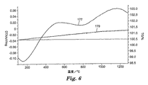
【0135】
図5を参照すると、ライン157は比較例Aの材料についてのDTAデータをプロットしたものであり;ライン159はTGAデータをプロットしたものである。図6を参照すると、ライン177は比較例Fの材料についてのDTAデータをプロットしたものであり;ライン179はTGAデータをプロットしたものである。図7を参照すると、ライン187は比較例Cの材料についてのDTAデータをプロットしたものであり;ライン189はTGAデータをプロットしたものである。TGAの実施を通じての試料の重量変化は、比較例Aでは0.22%;比較例Fでは0.73%;比較例Cでは1.16%であった。
【0136】
実施例1
ポリエチレン製のビンに、アルミナ粉末(「APA−0.5」)を171.6g、酸化イットリウム粉末(H.C.Starck社(マサチューセッツ州ニュートン)から入手)を83.4g、酸化ジルコニウム粉末(100重量%ZrO2(+HfO2)の公称組成で;Zirconia Sales社(Marietta、GA)から商品名「DK−2」として入手)を45g、分散剤(「DURAMAX D−30005」)を0.6g、蒸留水を100g装入したことを除き、実施例1の溶融材料、研磨剤粒子、および被覆研磨ディスクを比較例Aに記載したように調製した。溶融材料の色は白〜赤であった。
【0137】
図17および図18は、実施例1の溶融材料の研磨断面(比較例Aに記載したように調製)の走査電子顕微鏡(SEM)の顕微鏡写真である。図17および図18を参照すると、顕微鏡写真には、複数のコロニーを含む共晶誘導ミクロ構造が示されている。コロニーは、サイズ約5〜30マイクロメートルである。実施例1の材料の一部の粉末X線回折、および後方散乱モードのSEMを用いた研磨試料の試験に基づき、顕微鏡写真の白色部分は立方晶ZrO2、灰色部分は結晶質Y3Al5O12、暗い部分はα−Al2O3であったと考えられる。研磨断面で観察されたこれらの相の幅は約3マイクロメートルまでであった。コロニーを構成する共晶相は層状配列であった。アルミナ相は、三方晶形状を示す結晶として確認された。層状配列の少なくとも一部分の方向(すなわち、共晶晶出の方向)を観察した結果、隣接する層状配列が互いにぶつかる角度約120℃によって明らかである三方晶外形のアルミナの方向に従っていた。理論によって束縛されるものではないが、3元共晶における、または3元共晶付近の組成物の溶融物を結晶化する際に、初期アルミナが最初に三方晶形状で種結晶として結晶化すると考えられる。その結果としての層状共晶の結合成長は、少なくとも最初は種結晶の方向に従った。次いで、共晶コロニーは、共晶層状成長と共に同一の方向のアルミナ種結晶(または単一の種結晶)を含有した。さらに、コロニーの境界は、比較例Aの2元共晶(コロニー境界のすぐ近くにある共晶相の結晶の著しい粗さによって明らかにされる)で認められる相の粗さを示さないことが観察された。
【0138】
実施例1の平均微小硬度を、比較例Aに記載したように測定した結果、16.5GPaであった。
【0139】
実施例1のいくつかの粒子を白金製るつぼに入れ、50℃/時で1000℃に加熱し、1000℃で8時間(空気中)で維持し、次いで約100℃/時で室温に冷却した。加熱後の研磨剤粒子の色は白色だった。加熱後の実施例1の平均微小硬度は16.7GPaであった。
【0140】
実施例1および比較例B〜Dの研磨性能
実施例1および比較例B〜Dの被覆研磨ディスクの研磨性能を、比較例A〜Dに記載したように評価した。以下の表2にその結果を示す。
【0141】
【表2】
表2
実施例2
ポリエチレン製のビンに、アルミナ粉末(「APA−0.5」)を181.7g、酸化イットリウム粉末(H.C.Starck社(Newton、MA)から入手)を88.3g、酸化ジルコニウム粉末(「DK−2」)を30g、分散剤(「DURAMAX D−30005」)を0.6g、蒸留水を100g装入したことを除き、実施例2の溶融材料を比較例Aに記載したように調製した。
【0143】
図19は、実施例2の溶融材料の研磨断面(比較例Aに記載したように調製)の走査電子顕微鏡(SEM)の顕微鏡写真である。図19を参照すると、顕微鏡写真には、複数のコロニーを含む3元共晶誘導ミクロ構造が示されている。コロニーのサイズは約10〜40マイクロメートルである。実施例2の材料の一部分の粉末X線回折、および後方散乱モードのSEMを用いた研磨試料の試験に基づき、顕微鏡写真の白色部分は立方晶ZrO2、灰色部分は結晶質Y3Al5O12、暗い部分はα−Al2O3であったと考えられる。研磨断面で観察されたこれらの相の幅は約5マイクロメートルまでであった。さらに、樹枝状結晶状態で存在する大きな初晶(Al2O3およびY3Al5O12であると考えられる)が、研磨断面の一部の領域で観察され、厳密な共晶組成物からのその組成物の考えうるずれを示した。
【0144】
実施例3
ポリエチレン製のビンに、アルミナ粉末(「APA−0.5」)を141.3g、酸化イットリウム粉末(H.C.Starck社(Newton、MA)から入手)を68.7g、酸化ジルコニウム粉末(「DK−2」)を90g、分散剤(「DURAMAX D−30005」)を0.6g、蒸留水を100g装入したことを除き、実施例3の溶融材料を比較例Aに記載したように調製した。
【0145】
図20は、実施例3の溶融材料の研磨断面(比較例Aに記載したように調製)の走査電子顕微鏡(SEM)の顕微鏡写真である。図20を参照すると、顕微鏡写真には、複数のコロニーを含む3元共晶誘導ミクロ構造が示されている。コロニーのサイズは約10〜40マイクロメートルである。実施例3の材料の一部の粉末X線回折、および後方散乱モードのSEMを用いた研磨試料の試験に基づき、顕微鏡写真の白色部分は立方晶ZrO2、灰色部分は結晶質Y3Al5O12、暗い部分はα−Al2O3であったと考えられる。研磨断面で観察されたこれらの相の幅は約5マイクロメートルまでであった。さらに、樹枝状結晶状態で存在する大きな初晶(ZrO2であると考えられる)が、研磨断面の一部の領域で観察され、厳密な共晶組成物からのその組成物の考えうるずれを示した。
【0146】
比較例G
ポリエチレン製のビンに、アルミナ粉末(「APA−0.5」)を191.8g、酸化イットリウム粉末(H.C.Starck社(Newton、MA)から入手)を93.2g、酸化ジルコニウム粉末(「DK−2」)を15g、分散剤(「DURAMAX D−30005」)を0.6g、蒸留水を100g装入したことを除き、比較例Gの溶融材料を比較例Aに記載したように調製した。
【0147】
図21は、比較例Gの溶融材料の研磨断面(比較例Aに記載したように調製)の走査電子顕微鏡(SEM)の顕微鏡写真である。図21を参照すると、顕微鏡写真には、2元共晶誘導ミクロ構造が示されている。比較例Gの材料の一部分の粉末X線回折、および後方散乱モードのSEMを用いた研磨試料の試験に基づき、顕微鏡写真の白色部分は立方晶ZrO2、灰色部分は結晶質Y3Al5O12、暗い部分はα−Al2O3であったと考えられる。研磨断面で観察されたこれらの相の幅は約10マイクロメートルまでであった。さらに、厳密な共晶組成物からのその組成のずれを示す、Al2O3とY3Al5O12の結晶間に認められた大きな初晶(ZrO2であると考えられる)は相当に大きい。
【0148】
比較例H
ポリエチレン製のビンに、アルミナ粉末(「APA−0.5」)を201.9g、酸化イットリウム粉末(H.C.Starck社(Newton、MA)から入手)を88.3g、酸化ネオジウム粉末(Molycorp社(カリフォルニア州ブレア)から入手)を9.8g、分散剤(「DURAMAX D−30005」)を0.6g、蒸留水を100g装入したことを除き、比較例Hの溶融材料を比較例Aに記載したように調製した。
【0149】
図22は、比較例Hの溶融材料の研磨断面(比較例Aに記載したように調製)の走査電子顕微鏡(SEM)の顕微鏡写真である。図22を参照すると、顕微鏡写真には、共晶誘導ミクロ構造が示されている。比較例Hの材料の一部の粉末X線回折、および後方散乱モードのSEMを用いた研磨試料の試験に基づいて、顕微鏡写真の白色部分はNdリッチ相、灰色部分はネオジウムによって置換されたいくつかのイットリウムを有する結晶質イットリウム−アルミニウム−ガーネット、暗い部分はα−Al2O3であったと考えられる。研磨断面で観察されたこれらの相の幅は約10マイクロメートルまでであった。
【0150】
比較例I
(a)ポリエチレン製のビンに、アルミナ粉末(「APA−0.5」)201.9g、酸化イットリウム粉末(H.C.Starck社(Newton、MA)から入手)98.1gを装入し、(b)その粉末が、82モル%のAl2O3および18モル%のY2O3を提供する量で存在することを除き、比較例Iの溶融材料、研磨剤粒子、および被覆研磨ディスクを比較例Aに記載したように調製した。
【0151】
図23は、比較例Iの溶融材料の(比較例Aに記載したように調製)研磨断面の走査電子顕微鏡(SEM)の顕微鏡写真である。再び図23を参照すると、顕微鏡写真は、複数のコロニーを含む共晶誘導ミクロ構造を示している。コロニーのサイズは約10〜40マイクロメートルであった。比較例Iの材料の一部分の粉末X線回折、および後方散乱モードのSEMを用いた研磨試料の試験に基づき、顕微鏡写真の白色部分は結晶質Y3Al5O12、暗い部分はα−Al2O3であったと考えられる。研磨断面で観察されたこれらの相の幅は約1マイクロメートルまでであった。
【0152】
比較例A〜CおよびIの研削性能
比較例A〜CおよびIの被覆研磨ディスクの研削性能を、比較例A〜Dに関して上述したように評価した。その結果を以下の表3に示す。
【0153】
【表3】
表3
本発明の様々な改造や変更が、本発明の範囲および精神を逸脱することなく当業者には明らかになり、かつ本発明は本明細書中に記載された例示的な実施形態に過度に限定されないことを理解すべきである。
【図面の簡単な説明】
【図1】本発明による溶融研磨剤粒子を含む被覆研磨剤物品の部分断面概略図である。
【図2】本発明による溶融研磨剤粒子を含む結合研磨剤物品の透視図である。
【図3】本発明による溶融研磨剤粒子を含む不織研磨剤物品の拡大概略図である。
【図4】濃度三角形の平面に対するAl2O3−Y2O3−ZrO2系の状態図における液面の投影図である。
【図5】比較例Aの溶融材料の示差熱分析(DTA)プロットおよび熱重量分析(TGA)プロットである。
【図6】比較例Fの溶融材料のDTAプロットおよびTGAプロットである。
【図7】比較例Cの研磨剤粒子のDTAプロットおよびTGAプロットである。
【図8】比較例Aの溶融材料の磨き断面を示す走査電子顕微鏡写真である。
【図9】比較例Eの溶融材料の磨き断面を示す走査電子顕微鏡写真である。
【図10】比較例Fの溶融材料の磨き断面を示す走査電子顕微鏡写真である。
【図11】比較例Cの研磨剤粒子の磨き断面を示す走査電子顕微鏡写真である。
【図12】様々な加熱条件への曝露の比較例Cの研磨剤粒子の磨き断面を示す走査電子顕微鏡写真である。
【図13】様々な加熱条件への曝露の比較例Cの研磨剤粒子の磨き断面を示す走査電子顕微鏡写真である。
【図14】ガラス化結合材への曝露の比較例Cの研磨剤粒子の磨き断面を示す走査電子顕微鏡写真である。
【図15】比較例Fの材料の磨き断面を示す走査電子顕微鏡写真である。
【図16】特定の加熱条件への曝露の比較例Fの材料の磨き断面を示す走査電子顕微鏡写真である。
【図17】比較例Aの磨き断面を示す走査電子顕微鏡写真である。
【図18】比較例Aの磨き断面を示す走査電子顕微鏡写真である。
【図19】実施例2の溶融材料の磨き断面を示す走査電子顕微鏡写真である。
【図20】実施例3の溶融材料の磨き断面を示す走査電子顕微鏡写真である。
【図21】比較例Gの溶融材料の磨き断面を示す走査電子顕微鏡写真である。
【図22】比較例Hの溶融材料の磨き断面を示す走査電子顕微鏡写真である。
【図23】比較例Iの溶融材料の磨き断面を示す走査電子顕微鏡写真である。[0001]
Field of the invention
The present invention relates to molten abrasive particles and a method for producing the same. The molten abrasive particles can be incorporated into a variety of abrasive articles, including bonded abrasives, coated abrasives, nonwoven abrasives, and abrasive brushes.
[0002]
There are a variety of abrasive particles known in the art, such as diamond particles, cubic boron nitride particles, fused abrasive particles, and sintered ceramic abrasive particles, including sol-gel derived abrasive particles. In some polishing applications, the abrasive particles are used in powder form, while in other applications, the particles are used in abrasive products (eg, coated abrasive products, bonded abrasive products, nonwoven abrasive products, and abrasive Brush). Criteria used in selecting the abrasive particles used for a particular polishing application include polishing life, cutting speed, substrate surface finish, grinding efficiency and product cost.
[0003]
From about the 1900's to about the mid-1980's, the finest abrasive particles for polishing applications, such as those utilizing coated and bonded abrasive products, were typically fused abrasive particles. There are two general types of fused abrasive particles. (1) Fused alpha alumina abrasive particles (e.g., U.S. Pat. Nos. 1,161,620 (Coulter), 1,192,709 (Tone), and 1,247,337 ( See, Saunders et al., Nos. 1,268,533 (Allen), 2,424,645 (Baumann et al.) And (2) melting (sometimes referred to as "co-melting"). ) Alumina-zirconia abrasive particles (e.g., U.S. Patent Nos. 3,891,408 (Rowse et al.); 3,781,172 (Pett et al.); 3,893. No. 826 (Quinan et al.), No. 4,126,429 (Watson), No. 4,457,767 (Poon (P. on) et al.) and No. 5,143,522 (referring to Gibson (Gibson) et al)). See also, for example, U.S. Pat. Nos. 5,023,212 (Dubots et al.) And 5,336,280 (Dubots et al.) Which report some fused oxynitride abrasive particles. To do. Fused alumina abrasive particles typically charge an alumina source such as aluminum ore or bauxite and other desired additives into a furnace, heating the material above the melting point of the material and cooling the melt. Manufactured by producing a coagulum, breaking the coagulum into particles, and then sieving the particles to provide the desired abrasive particle size distribution. Fused alumina-zirconia abrasive particles are typical, except that both the alumina source and the zirconia source are charged to the furnace and the melt is cooled faster than the melt used to produce the fused alumina abrasive particles. It is manufactured in a similar manner. For fused alumina-zirconia abrasive particles, the amount of alumina source is typically about 50-80% by weight, and the amount of zirconia is 50-20% by weight zirconia. The process of producing fused alumina and fused alumina abrasive particles may include removing impurities from the melt prior to the cooling step.
[0004]
Although fused alpha-alumina abrasive particles and fused alumina-zirconia abrasive particles are still widely used in abrasive applications (including abrasive applications utilizing coated abrasive products and bonded abrasive products), since the 1980's many have been The finest abrasive particles for abrasive applications are sol-gel derived alpha alumina particles (eg, U.S. Patent Nos. 4,314,827 (Leitheiser et al.) And 4,518,397 (Lyseizer ( Leitheiser et al.), No. 4,623,364 (Cottringer et al.), No. 4,744,802 (Schwabel), No. 4,770,671 (Monroe et al.), No. 4,881,951 (Wood et al.), No. 4, Nos. 60,441 (Pellow et al.), 5,139,978 (Wood), 5,201,916 (Berg et al.), 5,366,523 (loan No. 5,429,647 (Larmie), No. 5,547,479 (Conwell et al.), No. 5,498,269 (Larmie), Nos. 5,551,963 (Larmie) and 5,725,162 (Garg et al.).
[0005]
The sol-gel derived alpha alumina abrasive particles may have a microstructure composed of very fine alpha alumina crystallites with or without the presence of added secondary phases. For example, the grinding performance of sol-gel derived abrasive particles on metal, as measured by the life of the abrasive product made with the abrasive particles, is dramatically greater than such products made from conventional fused alumina abrasive particles. long.
[0006]
Typically, the process of producing sol-gel derived abrasive particles is more complicated and expensive than the process of producing conventional molten abrasive particles. In general, sol-gel derived abrasive particles typically prepare a dispersion or sol comprising water, alumina monohydrate (boehmite) and optionally a peptizer (eg, an acid such as nitric acid), and gel the dispersion to a gel. And dried gelled dispersion, crushed dried dispersion into particles, sieved particles to produce particles of desired size, calcined particles to remove volatiles, calcined Manufactured by sintering the particles at a temperature below the melting point of alumina and sieving the particles to provide the desired abrasive particle size distribution. Metal oxide modifiers are often incorporated into sintered abrasive particles to change or otherwise modify the physical properties and / or microstructure of the sintered abrasive particles.
[0007]
There are a variety of abrasive products known in the art (also referred to as "abrasive articles"). Typically, the abrasive product comprises a binder and abrasive particles fixed within the abrasive product by the binder. Examples of abrasive products include coated abrasives, bonded abrasives, nonwoven abrasives, and abrasive brushes.
[0008]
Examples of bonded abrasive products include grinding wheels, cut-off wheels, and honing wheels. The main types of adhesive systems used to make bonded abrasive products are resinous, glassy and metallic. The resinous bonded abrasive uses an organic binder system (for example, a phenolic binder system) to combine and bond the abrasive particles and form a shaped mass (for example, US Pat. No. 4,741,743 (Narayanan) No. 4,800,685 (Haynes et al.), No. 5,038,453 (Narayanan et al.) And No. 5,110,332 (Narayanan). See)). Another major type is a vitreous wheel that uses a glass binder system to hold the abrasive particle mass together (eg, US Pat. No. 4,543,107 (Rue), No. 4). No. 4,898,587 (Hay et al.), 4,997,461 (Markhoff Matheny et al.) And 5,863,308 (Qi et al.). ). These glass bonds are usually aged at temperatures between 900C and 1300C. Currently, glassy wheels use both fused alumina abrasive particles and sol-gel derived abrasive particles. However, fused alumina zirconia is generally not incorporated into glassy wheels due in part to the thermal stability of alumina-zirconia. At the high temperatures that age the glass tie layer, the physical properties of the alumina-zirconia degrade, leading to a significant decrease in polishing performance. Metal bonded abrasive products typically use a sintered or plated metal to bond the abrasive particles.
[0009]
The abrasive industry has developed abrasive particles and abrasives that are easier to manufacture, less expensive to manufacture, and / or provide performance advantages compared to conventional abrasive particles and abrasive products. Abrasive products continue to be needed.
[0010]
Summary of the Invention
The present invention relates to a method for co-forming (preferably at least 20, 30, 40, 50, 60, 70, 75, 80, 85, 90, 95, 98, 99, or 100 volume percent based on the total metal oxide content of the particles) Melt crystalline abrasive particles comprising a crystalline material, wherein the eutectic material comprises at least (a) crystalline ZrO 2 2 And (b) (i) crystalline Al 2 O 3 (Ii) the first crystalline complex Al 2 O 3 ・ Y 2 O 3 Or (iii) a second different (ie, first crystalline complex Al 2 O 3 ・ Y 2 O 3 Different from) crystalline complex Al 2 O 3 ・ Y 2 O 3 The present invention provides molten crystalline abrasive particles comprising at least two eutectic crystals of: One preferred eutectic material comprises at least (a) ZrO 2 , (B) crystalline Al 2 O 3 And (c) the crystalline complex Al 2 O 3 ・ Y 2 O 3 Eutectic. Another preferred eutectic material comprises at least (a) crystalline ZrO 2 , (B) the first crystalline complex Al 2 O 3 ・ Y 2 O 3 And (c) a second different crystalline complex Al 2 O 3 ・ Y 2 O 3 Eutectic.
[0011]
In another embodiment, the present invention relates to the method of (preferably at least 20, 30, 40, 50, 60, 70, 75, 80, 85, 90, 95, 98, 99, based on the total metal oxide volume of the particles. Or 100% by volume of a eutectic material, wherein the eutectic material comprises at least (a) a crystalline complex Al 2 O 3 ・ Y 2 O 3 And (b) crystalline ZrO 2 The present invention provides molten crystalline abrasive particles comprising a eutectic of:
[0012]
In another embodiment, preferably, the molten crystalline abrasive particles according to the present invention comprise at least 30% by weight (or at least 40, 50, 60, 70 or even 80% by weight, based on the total metal oxide content of the particles). Also) Al 2 O 3 On a theoretical oxide basis. Preferred crystalline complex Al 2 O 3 ・ Y 2 O 3 Is yttrium aluminate exhibiting a garnet crystal structure. A preferred eutectic is Al 2 O 3 -Y 3 Al 5 O 12 -ZrO 2 It is.
[0013]
In another embodiment, the present invention provides a number of particles, wherein at least a portion of the number of particles having a particle size distribution ranging from fine particles to coarse particles are molten crystalline abrasive particles according to the present invention.
[0014]
In this application,
“Simple metal oxide” refers to a metal oxide containing one or more of the same metal element and oxygen (eg, AlO 3 , CeO 2 , MgO, SiO 2 And Y 2 O 3 ).
“Complex metal oxide” refers to a metal oxide containing two or more different metal elements and oxygen (eg, CeAl 11 O 18 , Dy 3 Al 11 O 12 , MgAl 2 O 4 And Y 3 Al 5 O 12 ).
"Complex AlO 3 "Metal oxide" is Al 2 O 3 And complex metal oxides containing one or more metal elements other than Al on a theoretical oxide basis (for example, CeAl 11 O 18 , Dy 3 Al 5 O 12 , MgAl 2 O 4 And Y 3 Al 5 O 12 ).
"Complex Al 2 O 3 ・ Y 2 O 3 "Means Al 2 O 3 And Y 2 O 3 Metal oxides (e.g., Y 3 Al 5 O 12 ).
"Complex Al 2 O 3 ・ Rare earth oxide ”means Al 2 O 3 And complex metal oxides containing rare earth oxides on a theoretical oxide basis (for example, CeAl 11 O 18 And Dy 3 Al 5 O 12 ).
"Rare earth oxide" refers to CeO 2 , Dy 2 O 3 , Er 2 O 3 , Eu 2 O 3 , Gd 2 O 3 , Ho 2 O 3 , La 2 O 3 , Lu 2 O 3 , Nd 2 O 3 , Pr 6 O 11 , Sm 2 O 3 , Th 4 O 7 , Tm 2 O 3 And Yb 2 O 3 Means on a theoretical oxide basis.
"Particle size" is the longest dimension of a particle.
[0015]
In another embodiment, the present invention relates to a method for producing the molten crystalline abrasive particles according to the present invention, comprising at least one Y to provide a melt. 2 O 3 Source, at least one rare earth oxide source and at least one ZrO 2 Providing a method comprising: melting a source; and converting the melt to the molten crystalline abrasive particles.
[0016]
The molten abrasive particles according to the present invention can be incorporated into various abrasive products such as coated abrasives, bonded abrasives, nonwoven abrasives and abrasive brushes.
[0017]
The present invention comprises contacting at least one molten abrasive particle according to the present invention (preferably a large number of molten abrasive particles according to the present invention) with a surface of a workpiece; Displacing at least one of the molten abrasive particles or the surface with respect to the other according to the present invention for polishing with the molten abrasive particles.
[0018]
Preferred fused abrasive particles according to the present invention provide superior grinding performance as compared to conventional fused abrasive particles. The preferred fused abrasive particles according to the present invention are prepared by vitrifying the preferred fused abrasive particles according to the present invention without significantly reducing the polishing performance of conventional fused alumina zirconia abrasive particles used by the vitrified bonding system. Microstructurally and chemically stable enough to allow use.
[0019]
Detailed description
The fused abrasive particles according to the present invention are produced by heating a suitable metal oxide source to form a melt, preferably a homogeneous melt, and then rapidly cooling the melt to provide a solidified mass. can do.
[0020]
More specifically, the molten abrasive particles according to the present invention comprise (on a theoretical oxide basis) Al 2 O 3 , Y 3 O 3 , ZrO 2 , And other optional additives (eg, other metal oxides and processing aids) can be made by charging the furnace. The metal oxide source can be added together and melted, for example, in a heating furnace, or added continuously and melted.
[0021]
For a solidified molten material containing a complex metal oxide, at least a portion of the metal oxide present in the molten metal oxide source (ie, the melt) reacts during processing of the solidified material to form a complex metal oxide. Form an object. For example, Al 2 O 3 Source and Y 2 O 3 The source reacts and Y 3 Al 5 O 12 (Ie, 5Al 2 O 3 + 3Y 2 O 3 → 2Y 3 Al 5 O 12 , YAlO 3 (That is, Al 2 O 3 + Y 2 O 3 → 2YAIO 3 ) Or Y 4 Al 2 O 9 (That is, Al 2 O 3 + 2Y 2 O 3 → Al 2 O 3 -).
[0022]
Al 2 O 3 , Y 3 O 3 , And ZrO 2 Depending on the relative proportions of the resulting solidified material, and ultimately the molten abrasive particles:
(A) crystalline Al 2 O 3 -Complex Al 2 O 3 ・ Metal oxide (complex Al 2 O 3 The metal oxide is, for example, Y 3 Al 5 O 12 -ZrO 2 Eutectic and crystalline Al 2 O 3 And / or
(B) crystalline Al 2 O 3 -Complex Al 2 O 3 A metal oxide (also in this case a complex Al 2 O 3 The metal oxide is, for example, Y 3 Al 5 O 12 -ZrO 2 Eutectic;
(C) crystalline Al 2 O 3 -Complex Al 2 O 3 A metal oxide (also in this case a complex Al 2 O 3 The metal oxide is, for example, Y 3 Al 5 O 12 -ZrO 2 Eutectic and crystalline complex Al 2 O 3 A metal oxide (also in this case a complex Al 2 O 3 The metal oxide is, for example, Y 3 Al 5 O 12 And / or
(D) crystalline Al 2 O 3 -Complex Al 2 O 3 A metal oxide (also in this case a complex Al 2 O 3 The metal oxide is, for example, Y 3 Al 5 O 12 -ZrO 2 Eutectic and crystalline ZrO 2 May be included.
[0023]
Al 2 O 3 Is Y 2 O 3 And form two complex metal oxides, the resulting solidified material, and ultimately the molten abrasive particles, will be 2 O 3 And Y 2 O 3 Depending on the relative proportion of:
(A) First crystalline complex First crystalline complex Al 2 O 3 A metal oxide (again, for example, Y 3 Al 5 O 12 Or YAlO 3 ) With Al 2 O 3 A metal oxide (for example, Y 3 Al 5 O 12 Or YAlO 3 )-A second different (i.e. a first crystalline complex Al) 2 O 3 -Different from metal oxide) crystalline complex Al 2 O 3 A metal oxide (for example, YAlO, respectively) 3 Or Y 4 Al 2 O 9 ) -ZrO 2 Eutectic;
(B) First crystalline complex Al 2 O 3 A metal oxide (again, for example, Y 3 Al 5 O 12 Or YAlO 3 )-A second different crystalline complex Al 2 O 3 A metal oxide (also in this case, for example, YAlO 3 Or Y 4 Al 2 O 9 ) -ZrO 2 Eutectic;
(C) a second different crystalline complex Al 2 O 3 A metal oxide (again, for example, YAlO 3 Or Y 4 Al 2 O 9 ) Together with the first crystalline complex Al 2 O 3 A metal oxide (again, for example, Y 3 Al 5 O 12 Or YAlO 3 )-A second different crystalline complex Al 2 O 3 A metal oxide (also in this case, for example, YAlO 3 Or Y 4 Al 2 O 9 ) -ZrO 2 Eutectic; and / or
(D) First crystalline complex Al 2 O 3 A metal oxide (again, for example, Y 3 Al 5 O 12 Or YAlO 3 )-A second different crystalline complex Al 2 O 3 A metal oxide (also in this case, for example, YAlO 3 Or Y 4 Al 2 O 9 ) -ZrO 2 Eutectic and crystalline ZrO 2 May be included.
[0024]
However, it is understood that the particular phase formed depends on several factors, including the composition of the melt and the solidification conditions. Usually, the composition of the melt and the solidification conditions are such that the majority of the resulting solidified material is occupied by the eutectic (ie, the formation of the solidified material depends on the eutectic of the various metal oxide phases present in the material). Such a condition that well corresponds to the ratio) is preferable. An exemplary eutectic of the abrasive particles according to the present invention is shown, for example, in the ternary phase diagram in FIG. More specifically, the diagram of FIG. 2 O 3 -Y 2 O 3 -ZrO 2 FIG. 3 represents the projection of the liquidus plane in the phase diagram for the system. A preferred eutectic is Al 2 O 3 Eutectic rich in
[0025]
While not wishing to be bound by theory, certain metastable conditions during formation of the solidified material may result in the formation of another eutectic. For example, under normal stable conditions, the eutectic that forms is Al 2 O 3 / Y 3 Al 5 O 12 / ZrO 2 And under certain metastable conditions, Al 2 O 3 / Y 3 Al 5 O 12 / ZrO 2 Al instead of or in addition to eutectic 2 O 3 / YAlO 3 / ZrO 2 A eutectic may form.
[0026]
Complex Al 2 O 3 ・ Y 2 O 3 It is also within the scope of this invention to replace some of the yttrium and / or aluminum cations in (eg, yttrium aluminate exhibiting a garnet crystal structure) with other cations. For example, the complex Al 2 O 3 ・ Y 2 O 3 It is possible to replace a portion of the Al cation therein with at least one cation of an element selected from the group consisting of Cr, Ti, Sc, Fe, Mg, Ca, Si, Co, and combinations thereof. For example, the complex Al 2 O 3 ・ Y 2 O 3 Some of the Y cations in the above are converted to Ce, Dy, Er, Eu, Gd, Ho, La, Lu, Nd, Pr, Sm, Th, Tm, Yb, Fe, Ti, Mn, V, Cr, Co, Ni , Cu, Mg, Ca, Sr, and combinations thereof. Similarly, replacing a portion of the aluminum cation in the alumina is also within the scope of the present invention. For example, Cr, Ti, Sc, Fe, Mg, Ca, Si, and Co can replace aluminum in the alumina structure. The cation substitution described above may affect the properties (eg, hardness, toughness, strength, thermal conductivity, etc.) of the abrasive particles.
[0027]
In addition, other eutectics will be apparent to those of skill in the art upon reviewing the present disclosure. For example, phase diagrams representing various eutectics are known in the art.
[0028]
The fused abrasive particles according to the invention containing a eutectic material are usually composed of eutectic colonies. Individual colonies have nearly uniform microstructural characteristics (eg, similar in size and orientation of the constituent phase crystals inside the colony). Usually, when impurities are present in the molten crystalline abrasive particles according to the invention, these impurities tend to separate at the colony boundaries, are present alone and / or have a crystalline phase and / or amorphous (glass ) As a reaction product (eg, complex Al) 2 O 3 .Metal oxide and / or complex Y 2 O 3 -As a metal oxide).
[0029]
Generally, (a) single crystals of three different metal oxides (for example, Al 2 O 3 , Y 3 Al 5 O 12 , And ZrO 2 (B) single crystals of two different metal oxides (eg, single crystal Al 2 O 3 And single crystal ZrO 2 ) And multiple crystals of different metal oxides (eg, polycrystalline Y 3 Al 5 O 12 ), (C) one single crystal of metal oxide (for example, single crystal Al 2 O 3 Or ZrO 2 ) And multiple crystals of different metal oxides (eg, polycrystalline Y 3 Al 5 O 12 And polycrystalline ZrO 2 ) Or (d) three different polycrystalline metal oxides (eg, polycrystalline Al 2 O 3 , Polycrystalline Y 3 Al 5 O 12 And polycrystalline ZrO 2 ).
[0030]
Colonies can be of any of a variety of shapes, typically ranging from essentially spheres to cylinders. The composition, phase, and / or microstructure (eg, crystalline (ie, single or polycrystalline) and crystal size) of each colony can be the same or different. The orientation of crystals within a colony may vary from one colony to another. The phases that make up some eutectic colonies may exist in various shapes, such as, for example, from sticks or platelets to “Kanji characters”. Such differences between colonies may even exist between adjacent colonies.
[0031]
The microstructure may be a mixture of two component phases in a "Kanji character" arrangement, the third phase being present as bars or plates. Alternatively, for example, the two component phases may be present as an interpenetrating network, for example, with a third phase present as a plate or rod.
[0032]
Colony number, colony size and composition are affected, for example, by melt composition and coagulation conditions. While not wishing to be bound by theory, it is believed that the closer the melt composition is to the exact eutectic composition, the fewer colonies formed. However, in another embodiment, slow unidirectional solidification of the melt also tends to minimize the number of colonies that form, while multidirectional solidification at a relatively higher cooling rate causes the colonies that form to form. It is conceivable that the number tends to increase. The rate of solidification of the melt (ie, cooling rate) and / or the multi-directional solidification of the melt affects the type and / or number of microstructural defects (eg, holes) present in the resulting molten abrasive particles Tend. For example, although not wishing to be bound by theory, relatively rapid solidification (ie, solidification at a relatively high cooling rate) and / or multidirectional solidification may be due to the presence of microscopic particles present in the resulting molten abrasive particles. There is a tendency to increase the type and / or number of structural defects (eg, holes). However, relatively slow solidification tends to increase the size and / or crystals of the colonies present in the solidified material. However, for example, eliminating colony formation may be possible through slow controlled cooling. Thus, in selecting the cooling rate and / or the degree of multidirectional solidification, the cooling rate needs to be increased or decreased to achieve an optimal balance between the desired microstructure properties and the undesirable microstructure properties associated with the various cooling rates. There can be.
[0033]
In addition, for a given composition, the size of the colonies and the phases present within the colonies tend to decrease as the cooling rate of the melt increases. Typically, the eutectic colonies in the molten abrasive particles according to the present invention average less than 100 micrometers, preferably less than 50 micrometers, where such sizes for a given colony are determined by scanning electron microscopy (SEM ) Is the average of the two largest dimensions measured from the polished section of the colony, as observed in (1). Typically, the smallest dimension of the crystalline phase constituting the eutectic in the colony as measured from the polished cross section of the colony observed by SEM is less than 10 micrometers, preferably less than 5 micrometers, more preferably Less than 1 micrometer, or even less than 0.5 micrometer.
[0034]
Some abrasive particles according to the present invention also include primary crystals of at least one of the metal oxide phases that make up the eutectic component of the abrasive particles. For example, if the eutectic part is Al 2 O 3 Phase, complex Al 2 O 3 ・ Y 2 O 3 (For example, Y 3 Al 5 O 12 ) Phase, and ZrO 2 If composed of phases, the microstructure is also Al 2 O 3 , Complex Al 2 O 3 ・ Y 2 O 3 Or ZrO 2 Of the melt, from which the abrasive particles are formed, have a composition of Al 2 O 3 , Complex Al 2 O 3 ・ Y 2 O 3 Or ZrO 2 It is thought that it occurs when it is rich.
[0035]
It is believed that the formation of primary crystals results from a deviation from a particular eutectic fraction. The greater the bias, the greater the overall proportion of primary crystals. Primary crystals may be found in a variety of shapes, typically ranging from rod-like to dendritic. While not wishing to be bound by theory, it is believed that the presence and / or formation of primary crystals adjacent to the colony can affect the resulting microstructure of the colony. In some cases, the primary crystals present in the abrasive particles (eg, primary Al 2 O 3 It can be advantageous to have crystals) (eg for improved polishing performance). However, it is also conceivable that the polishing performance of the abrasive particles tends to decrease as the size of the primary crystal increases.
[0036]
Further, while not wishing to be bound by theory, small additions of metal oxides other than those constituting the eutectic (eg, less than 5% by weight) can affect colony boundaries, Next, it is thought that the properties (eg, hardness and toughness) of the abrasive particles can be affected.
[0037]
Al for producing abrasive particles according to the invention 2 O 3 Sources (on a theoretical oxide basis) include those known in the art for producing conventional fused alumina abrasive particles and alumina-zirconia abrasive particles. Commercially available Al 2 O 3 Sources include bauxite (including both natural and synthetically produced bauxite), calcined bauxite, aluminum oxide trihydrate (eg, boehmite and gibbsite), Bayer process alumina, aluminum ore, gamma alumina, alpha alumina, aluminum salts , Aluminum nitrate and combinations thereof. Al 2 O 3 Source is Al 2 O 3 Or Al 2 O 3 May simply occur. Alternatively, Al 2 O 3 Source is Al 2 O 3 And Al 2 O 3 One or more metal oxides (complex Al 2 O 3 A metal oxide (for example, Y 3 Al 5 O 12 )) Or may contain or give rise to).
[0038]
Y for producing abrasive particles according to the invention 2 O 3 Commercial sources of (eg, on a theoretical oxide basis) include yttrium oxide powder, yttrium, yttrium-containing ores, and yttrium salts (eg, yttrium carbonate, yttrium nitrate, yttrium chloride, yttrium hydroxide, and combinations thereof). Can be Y 2 O 3 Source is Y 2 O 3 Or Y 2 O 3 Only can be provided. Or Y 2 O 3 Source is Y 2 O 3 And Y 2 O 3 Other than one or more metal oxides (complex Y 2 O 3 A metal oxide (for example, Y 3 Al 5 O 12 ) Materials, or materials containing them).
[0039]
ZrO for producing abrasive particles according to the invention 2 Commercial sources (on a theoretical oxide basis) of zirconium oxide powder, zircon sand, zirconium, zirconium-containing ores, and zirconium salts (e.g., zirconium carbonate, zirconium acetate, zirconium nitrate, zirconium chloride, zirconium hydroxide, and Combinations thereof). Also or alternatively, ZrO 2 Source is ZrO 2 , As well as other metal oxides such as hafnia.
[0040]
Preferably, the molten abrasive particles according to the present invention comprise, on a theoretical chloride basis, about 40 to about 90 mole% (more preferably, about 50 to about 80 mole%) Al 2 O 3 About 5 to about 50 mole% (more preferably, about 10 to about 40 mole%) of ZrO; 2 And about 3 to about 30 mole% (more preferably, about 5 to about 20 mole%) of Y 2 O 3 including.
[0041]
Optionally, the molten abrasive particles according to the present invention may further comprise other metal oxides (ie, Al 2 O 3 , Y 2 O 3 , And ZrO 2 Other metal oxides). The addition of certain metal oxides alters the crystal structure or microstructure of the resulting fused abrasive particles. For example, without being bound by any theory, a metal oxide containing a particular metal oxide or compound (e.g., based on the total metal oxide content of the molten abrasive particles, , Even when used at 0.01 to 5 weight percent). Each other or Al 2 O 3 , Y 2 O 3 And / or ZrO 2 The presence of these metal oxides, which may be in the form of a reaction product with it, may affect the breaking properties and / or the microstructure of the molten abrasive particles and / or the abrasive properties of the abrasive particles. . The optional metal oxide also acts as a processing aid, for example, increasing the density of the molten abrasive particles by reducing the size and / or number of pores of the molten abrasive particles. Optional metal oxides can also act as processing aids, for example, increasing or decreasing the effective melting temperature of the melt. Therefore, specific metal oxides can be added for processing.
[0042]
The fused abrasive particles according to the present invention generally have less than 50 weight percent (more generally less than 20 weight percent; optionally from 0.01 to 100 weight percent, based on the total metal oxide content of each abrasive particle. Metal oxides (on a theoretical oxide basis) other than alumina, yttria, and zirconia in the range of 5 weight percent (otherwise in the range of 0.1 to 1 weight percent). Other metal oxide sources are readily available commercially.
[0043]
Examples of optional metal oxides include, on a theoretical oxide basis, rare earth oxides, BaO, CaO, Cr 2 O 3 , CoO, Fe 2 O 3 , HfO 2 , Li 2 O, MgO, MnO, NiO, SiO 2 , TiO 2 , Na 2 O, Sc 2 O 3 , SrO, V 2 O 3 , ZnO, and combinations thereof. With further reference to rare earth oxides, rare earth oxide powders, rare earth metals, rare earth containing ores (eg, bastnaesite and monazite), rare earths are commercially available sources of rare earth oxides used to produce the abrasive particles according to the present invention. Salts, rare earth nitrates, and rare earth carbonates. The rare earth oxide source may contain or simply provide the rare earth oxide. Alternatively, the rare earth oxide source is a rare earth oxide and one or more metal oxides other than the rare earth oxide (a complex rare earth oxide / other metal oxide (for example, Dy 3 Al 5 O 12 , CeAl 11 O 18 Etc.) or materials containing it).
[0044]
As a metal oxide source for producing the abrasive particles according to the present invention, fused abrasive particles (e.g., fused alumina abrasive particles) or other molten materials (e.g., fused alumina material) having the same or different compositions. These are combined with the rest of the source of the metal oxide to provide the molten abrasive particles of the desired composition.
[0045]
A reducing agent such as a carbon source may be added to reduce impurities during the melting process. Examples of carbon sources include coal, graphite or petroleum coke. The amount of carbon contained in the charge to the furnace is typically no more than 5%, more typically no more than 3%, more typically no more than 2% by weight of the charge. Iron may also be added to the furnace charge to help remove impurities. For example, iron can be combined with impurities to produce a material that can be magnetically removed from the melt or crushed solidified material.
[0046]
It is also within the scope of the present invention to include metal borides, carbides, nitrides and combinations thereof in the fused abrasive particles according to the present invention. Such materials may even be present within the eutectic material (eg, as inclusions). Examples of metal borides, carbides and nitrides may include titanium diboride, aluminum carbide, aluminum nitride, titanium carbide, titanium nitride, silicon carbide, boron carbide and boron nitride. Such materials are known in the art and are commercially available.
[0047]
With regard to the particular choice of metal oxide source and other additives for producing the molten abrasive particles according to the present invention, for example, the desired composition and microstructure of the resulting abrasive particles, the resulting polishing Used to produce the desired physical properties (e.g., hardness or toughness) of the abrasive particles, to avoid or minimize the presence of undesired impurities, the desired abrasive properties of the resulting abrasive particles, and / or to manufacture the abrasive particles. It is typical that certain steps are taken into account, including the purification of the raw materials before and / or during the melting and / or solidification.
[0048]
The metal oxide source and other additives can be in any form suitable for the process and equipment used to produce the abrasive particles. The raw materials can be melted using techniques and equipment known in the art for the production of conventional fused alumina and alumina-zirconia abrasive particles (eg, US Pat. No. 3,781,172 ( Pett et al.), 3,891,408 (Rowse et al.), 4,035,162 (Brothers et al.), 4,070,796 (Scott), 4,073,096 (Ueltz et al.). Nos. 4,126,429 (Watson), 4,457,767 (Poon et al.), 5,143,522 (Gibson et al.), And Re.31,128 (Walker et al.). thing).
[0049]
Examples of furnaces for melting metal oxide sources and other additives include arc furnaces, pit furnaces, arc tap furnaces, electric furnaces, electric arc furnaces and gas fired furnaces. Suitable electric furnaces include furnaces in which the electrodes are arranged to create a "kissing arc", furnaces in which the lower tip of the electrodes are not in contact with the molten mass, and resistive heating via current passing through the melt. Furnaces include submerging the electrodes in a molten mass to provide.
[0050]
The heating furnace may have a lining (sometimes called a “shell” or “skeleton”) that covers the inside wall of the heating furnace. The lining may be made of a material having a different composition than the molten abrasive particles. However, it is usually preferred that the lining of the furnace be made of a composition or material similar to the composition of the molten abrasive particles, and sometimes even the same or the same composition or material. Thus, the possibility of fouling of the melt is reduced or minimized if the outer surface (exposed surface) of the lining melts during the process.
[0051]
For some metal oxide sources and other additives, the raw materials may also be preheated before the raw materials are introduced into the furnace or before the raw materials are separately combined with other metal oxide sources and other additives. It may be desirable. For example, if carbonates, nitrates or other salts are used as the metal oxide source, calcine such materials (e.g., at about 400-1000 <0> C) before adding them with other metal oxide source materials. (By heating them in air).
[0052]
Generally, if a metal oxide source and other additives are present, they are heated to the molten state and mixed until the melt is homogeneous. Typically, the melt is heated to and maintained at a temperature at least 50 ° C. (preferably at least 100 ° C.) above the melting point of the melt. If the temperature of the melt is too low, the viscosity of the melt may be undesirably high, thus homogenizing the various metal oxide sources and other additives that make up the melt, or reducing the melt. It makes it more difficult to pour from the furnace or transfer the melt from the furnace to another wind. If the temperature of the melt is too high and / or the melt is heated for too long, energy is wasted and undesirable volatilization of the components of the melt may occur.
[0053]
Optionally, if there is a metal oxide source and other additives (e.g., volatile components (e.g., water or organic solvents) that help to form a homogeneous mixture or blend), a melt may be formed. In some cases, it may be desirable to mix them or blend them differently. For example, a particulate metal oxide source can be milled (ball milling) to mix the materials together and to reduce the size of the particulate material. Other techniques for mixing or blending the metal oxide source and other additives, if present, prior to forming the melt include high shear mixers, paddle mixers, V-blenders. And a tumbler. Milling times can range from minutes to hours, or even days. Optionally, transient materials such as water and organic solvents may be removed from the mixture or blend of metal oxide source and other additives, for example, by heating before forming a melt. For ease of handling, the metal oxide source and other additives may be agglomerated before they enter the furnace.
[0054]
The atmosphere above the melt may be at atmospheric, superatmospheric, or subatmospheric pressure. However, a pressure below atmospheric pressure may be preferred to reduce the number of holes in the resulting solidified material. The atmosphere over the melt may be controlled to provide an oxidizing, reducing, or inert atmosphere that can affect the chemistry of the melt.
[0055]
The reducing conditions during the melting can help to refine the melt. In addition to, or as an alternative to, adding a reducing agent to the melt, suitable reducing conditions may be obtained using a carbon electrode in an electric arc melting furnace. Under suitable reducing conditions, some impurities (eg, silica, iron oxide and titania) convert to their individual molten metal forms, thus leading to higher specific gravity for the melt. These free metal impurities will then tend to sink to the bottom of the furnace.
[0056]
In another embodiment, it may be desirable to oxidize free metals present in the melt before cooling the melt (eg, before transferring the melt from the furnace). For example, an oxygen lance may be inserted into the melt just prior to transferring the melt from the furnace (see, for example, U.S. Patent No. 960,712).
[0057]
The melt can be cooled using any of a variety of methods known in the art. Typically, the furnace containing the melt can be tilted so that the melt can be injected onto or into the heat sink. Examples of the heat sink include metal balls (for example, cast iron balls or carbon steel balls), metal rods, metal plates, metal rolls, and the like. In some cases, the interior of these heat sink materials can be cooled (eg, water cooled or a suitable coolant) to increase the cooling rate. The heat sink material may be part of a pre-melted material (having the same or different composition as the material to be solidified), including materials for making conventional fused alumina-zirconia, or other refractory materials.
[0058]
Further, with respect to the heat sink, it is possible to cool the melt by pouring the melt onto or between the metal balls. Balls typically range in diameter from about 1 to 50 cm, more typically from 5 to 25 cm. The melt may be cooled using a book mold. Suitable book molds consist of a plurality of sheets (eg, metal or graphite) that are relatively close to one another. The plates are usually less than 10 cm apart, typically less than 5 cm, preferably less than 1 cm. The melt may be poured into a graphite or cast iron mold to form a slab. It is generally preferred that such "slabs" be relatively thin to achieve faster cooling rates.
[0059]
It is believed that the cooling rate affects the microstructure and physical properties of the solidified material, and thus the molten abrasive particles. Preferably, the melt is cooled quickly because the size of the crystalline phase of the solidified material generally decreases as the cooling rate increases. Preferred cooling rates are at least 500 ° C / min, more preferably at least 1000 ° C / min, and even more preferably at least 1500 ° C / min. The rate of cooling may depend on several factors, including the melt chemistry, the melting point of the melt, the heat sink type and the heat sink material.
[0060]
Rapid cooling is performed under controlled atmospheres such as reducing, neutral or oxidizing environments to maintain and / or affect the desired crystalline phase, oxidation state, etc. during cooling. May go.
[0061]
Additional details regarding the cooling of the melt can be found, for example, in US Pat. No. Re. 31,128 (Walker et al.), US Pat. No. 3,781,172 (Pett et al.), 4,070. 4,796,887 (Ueltz et al.), 4,415,510 (Richmond), 4,439,845 (Richmond). )) And 5,143,522 (Gibson et al.).
[0062]
The resulting (coagulated) molten material is typically larger in size than desired for the abrasive particles. The molten material is converted into smaller pieces using art-known crushing and / or milling techniques, including roll crushing, canary milling, jaw crushing, hammer milling, ball milling, jet milling and impact crushing, and the like. It is possible or typically converted. In some cases, it is desirable to have two or multiple crushing steps. For example, after the molten material has solidified, the molten material may take the form of a relatively large bulk structure (eg, a diameter greater than 5 cm). The first crushing step may include crushing these larger chunks or "chunks" to form smaller pieces. This crushing of these chunks may be performed using a hammer mill, impact crusher or jaw crusher. Thereafter, these smaller pieces are subsequently crushed to produce the desired particle size distribution. In order to produce the desired particle size distribution (sometimes called grit size or grit grade), it may be necessary to perform a multiple crushing step. Generally, the crushing conditions are optimized to achieve the desired particle shape and particle size distribution.
[0063]
The shape of the molten abrasive particles according to the present invention depends, for example, on the composition and / or microstructure of the abrasive particles, the shape of the cooled particles, and the hammer that breaks the solidified material (ie, the crushing technique used). Generally, where a "chunky" shape is preferred, more energy may be used to achieve this shape. Conversely, if a "sharp" shape is preferred, less energy may be used to achieve this shape. The crushing technique may be varied to achieve different desired shapes. Alternatively, the abrasive particles may be formed directly into the desired shape by pouring the melt into a mold or allowing the melt to form in the mold.
[0064]
The shape of the abrasive particles may be measured by various techniques known in the art, including apparent density and aspect ratio. The larger the abrasive particle size, the higher the apparent density due to the large clumps associated with the larger particle size. Therefore, when comparing apparent densities, the comparison should be made with abrasive particles having essentially the same particle size. In general, the higher the apparent density value, the more the abrasive particles are considered to have a "chunkier" shape. Conversely, the lower the apparent density value, the more abrasive particles are considered to be "sharper". Another way to measure sharpness is by aspect ratio. For example, grade 36 aspect ratios can range from about 1: 1 to about 3: 1, typically from about 1.2: 1 to about 2: 1.
[0065]
The apparent density of the abrasive particles can be measured according to ANSI standard B74.4-1992 (1992). Generally, the apparent density is measured by pouring the abrasive particle sample through the funnel so that the abrasive particles fall through the funnel in a free flowing manner. A collector (typically a graduated cylinder) is directly below the funnel. A predetermined volume of abrasive particles is collected and then weighed. Apparent density is calculated in terms of weight / volume.
[0066]
Abrasive particles according to the present invention can be made using techniques known in the art including the use of industry certification ratings such as ANSI (American Standards Association), FEPA (European Federation of Abrasives) and JIS (Japanese Industrial Standards). It can be used to screen and sort. Abrasive particles according to the present invention typically have from about 0.1 to about 5000 micrometers, more typically from about 1 to about 2000 micrometers, preferably from about 5 to about 1500 micrometers, more preferably from about 100 to about 1500 micrometers. It may be used in a wide range of particle sizes, ranging in size from up to about 1500 micrometers.
[0067]
For a given particle size distribution, there is a range of particle sizes from coarse to fine. In the abrasive art, this range is sometimes referred to as the "fraction", "control" and "fine" portions. Abrasive particles rated according to industry-recognized rating standards define a particle size distribution for each nominal grade within numerical limits. Such industry certification ratings include those known as the American National Standards Institute (ANSI) standards, the European Federation of Abrasive Industries (FEPA) standards, and the Japanese Industrial Standards (JIS) standards. ANSI grade designations (ie, defined nominal grades) include ANSI4, ANSI6, ANSI8, ANSI16, ANSI24, ANSI36, ANSI40, ANSI50, ANSI60, ANSI80, ANSI100, ANSI120, ANSI150, ANSI180, ANSI220, ANSI240, ANSI280, ANSI320. , ANSI 360,
[0068]
After crushing and sieving, there are typically a number of different abrasive particle size distributions or grades. These multiple grades may not match the needs of the manufacturer or supplier at that particular point in time. To minimize inventory, it is possible to recycle unrequired grades back into molten mass. This recirculation may be performed after a crushing step in which the particles are large chunks or smaller pieces (sometimes called "fine") that have not been sieved to a particular distribution. The charge to the furnace for producing the fused abrasive particles according to the invention consists of 0-100% by weight, typically between 0 and 50% by weight, of recycled molten abrasive particles somewhere. You may.
[0069]
Usually, the true density of the fused abrasive particles according to the present invention, sometimes also referred to as specific gravity, is generally at least 80% of the theoretical density, but abrasive particles having a lower true density can be useful for polishing applications. sell. Preferably, the true density of the fused abrasive particles according to the present invention is at least 85% of the theoretical density, more preferably at least 90% of the theoretical density, even more preferably at least 95% of the theoretical density.
[0070]
Typically, the fused abrasive particles according to the present invention have an average hardness (ie, resistance to deformation, also referred to as "microhardness") of at least 11 GPa; preferably at least 12, 13, or 14 GPa, more preferably at least 15 GPa. And more preferably at least 16 GPa, at least 17 GPa, or even at least 18 GPa.In another aspect, the fused abrasive particles according to the present invention generally have an average toughness (ie, resistance to breakage) of at least 2.0 MPa · m. 1/2 Preferably at least 2.5 MPa · m 1/2 , More preferably at least 3.0 MPa · m 1/2 , More preferably at least 3.3 MPa · m 1/2 , At least 3.5 MPa · m 1/2 Or even at least 3.8 MPa · m 1/2 It is.
[0071]
For example, it is within the scope of the present invention to provide a surface coating on the molten abrasive particles. Such surface coatings are known, for example, to improve the adhesion between the abrasive particles and the binder material in the abrasive particles. Surface coatings are described, for example, in U.S. Pat. Nos. 1,910,444 (Nicholson), 3,041,156 (Rowse et al.), And 4,997,461 (Mark Hofmatney ( Markhoff Matheny et al.), 5,009,675 (Kunz et al.), 5,042,991 (Kunz et al.) And 5,085,671 (Martin et al.). It is described in. Further, in some cases, the addition of a coating improves the abrasive properties of the abrasive particles. In another embodiment, a surface coating may improve the adhesion between the abrasive particles of the present invention and a binder.
[0072]
In another aspect, after the abrasive particles according to the present invention are produced, the abrasive particles that improve physical properties and / or grinding performance can be further heat treated. This heat treatment step can be performed in an oxidizing atmosphere. Generally, this heat treatment step is performed at a temperature of about 1100 ° C to 1600 ° C, usually at a temperature of 1200 ° C to 1400 ° C. The time can range from about 1 minute to several days, and usually ranges from about 5 minutes to 1 hour.
[0073]
Other suitable preparation techniques for producing fused abrasive particles according to the present invention are disclosed herein, as well as, for example, U.S. Patent Application Serial No. 09,495,978, filed February 2, 2000, respectively. Nos. 09 / 496,422, 09 / 496,638, and 09 / 496,713, as well as 09 / 618,876 and 09 filed on July 19, 2000, respectively. No./619,106, No.09 / 619,191, No.09 / 619,192, No.09 / 619,215, No.09 / 619,289, No.09 / 619,563, No.09 / 619. , 729, 09 / 619,744, and 09 / 620,262 will be apparent to those skilled in the art.
[0074]
For certain fused abrasive particles according to the present invention, the eutectic phase comprising the colonies (eg, Al 2 O 3 -Y 3 Al 5 O 12 -ZrO 2 ) Has a lamellar arrangement in which one crystal phase (for example, alumina crystal) shows a trigonal shape. Further, the orientation of at least some of the adjacent lamellae (ie, the orientation of eutectic crystallization) follows the orientation of the trigonal (shape) profile at an angle of about 120 degrees. While not wishing to be bound by theory, during crystallization of a melt of composition at or near the three-dimensional eutectic, the primary crystals of one phase (eg, alumina) assume a trigonal shape. It is conceivable that the seeds taken could be crystallized first. The resulting coupled growth of the eutectic in the form of a lamella follows at least initially the seed orientation. The eutectic colony then contains a seed (eg, alumina seed) (or a single seed) of the same orientation with the eutectic lamella growth. In addition, the colony boundaries are phase coarsened as observed in two-dimensional eutectics, such as the phase coarseness observed for Comparative Example A (indicated by significant coarsening of the crystals of the eutectic phase immediately adjacent to the colony boundary). May not be shown.
[0075]
Preferred abrasive particles according to the present invention are thermally stable at elevated temperatures, as compared to conventional fused alumina zirconia materials (including alumina-zirconia abrasive particles available from Norton Company of Worcester, Mass. Under the trade name "NORZON"). It is. When heating alumina-zirconia eutectic abrasive particles available from Norton Company of Worcester, Mass. Under the trade name "NORZON", e.g., in air to at least about 350 [deg.] C., typically at least a portion of the zirconia is typically tetragonal. And / or undergo a phase transition from cubic to monoclinic. This phase transition is usually detrimental to the structural integrity of the alumina-zirconia material because it involves a volume change to the zirconia crystalline phase. In addition, it has been observed that such phase transitions occur preferentially at the boundaries of eutectic colonies, so that the phase transitions tend to weaken the boundaries, and in turn the mechanical properties (ie, hardness, Strength, etc.). In addition, various impurities, which are typically separated at the eutectic colony boundaries during solidification of the melt, may also undergo volumetric structural changes (eg, due to oxidation) and the mechanical properties (ie, hardness, strength) of the material Etc.).
[0076]
In contrast, preferred abrasive particles according to the present invention generally do not exhibit a eutectic phase transformation when heated to up to 1000 ° C. (and in some cases up to 1400 ° C.) in air, and It is stable. While not wishing to be bound by theory, it is believed that such thermal stability allows such abrasive particles to be incorporated into vitrified bonded abrasives.
[0077]
The thermal stability of certain preferred abrasive particles according to the present invention includes differential thermal analysis (DTA), thermogravimetric analysis (TGA), X-ray diffraction, hardness measurement, microstructure analysis, discoloration, and interaction with glass bonds. It can be measured or described using a variety of different methods, including: The thermal stability of the abrasive particles can depend, for example, on the composition, chemistry of the abrasive particles, and process conditions.
[0078]
One test for determining the thermal stability of abrasive particles involves measuring the average hardness of the abrasive particles before and after heating in air at 1000 ° C. for 4 hours in air. Example A (see below). Although the average microhardness may be somewhat reduced after heating at 1000 ° C. for 4 hours in air, the preferred abrasive particles according to the invention after heating at 1000 ° C. for 4 hours in air are the microhardness of such abrasive particles before heating. At least 85% (preferably at least 90%, more preferably at least 95%, even more preferably about 100% or more).
[0079]
The thermal stability of the abrasive particles can also be observed using a scanning electron microscope (SEM), where the average microstructure (eg, porosity, crystal structure, colony size and crystal size (eutectic, and Primary crystals, if present), and the integrity of the abrasive particles are tested before and after heating at 1000 ° C. in air for 4 hours.
[0080]
Furthermore, the thermal stability of the abrasive particles can also be shown by comparing the color of the abrasive particles before and after heating at 1000 ° C. for 4 hours in air. The microstructure of certain preferred abrasive particles according to the present invention is substantially the same before and after heating at 1000 ° C. for 4 hours in air.
[0081]
The thermal stability of the abrasive particles may be illustrated by comparing the powder XRD results of the abrasive particles before and after heating at 1000 ° C. for 4 hours in air. As discussed above, when heating an alumina-zirconia eutectic material in air, typically at least a portion of the zirconia undergoes a phase transition from tetragonal and / or cubic to monoclinic. The effect of this phase transition is typically significant enough to be observed via powder XRD. In contrast, the eutectic phase of certain preferred abrasive particles according to the present invention does not show such a phase transition when heated to 1000 ° C. in air, and thus such a transition of the eutectic phase is observed in the XRD results. Not done.
[0082]
The fused abrasive particles according to the present invention include coated abrasive products, bonded abrasive products (including vitrified bonded wheel wheels, resinous bonded wheel wheels and metal bonded wheel wheels, cut-off wheels and honing wheels), nonwoven abrasives. It can be used in conventional abrasive products such as products and abrasive brushes. Typically, the abrasive product (ie, the abrasive article) comprises a binder and abrasive particles, at least a portion of which are fused abrasive particles according to the present invention secured within the abrasive product by the binder. Methods of making and using such abrasive products are well known to those skilled in the art. Further, the molten abrasive particles according to the present invention can be used in abrasive applications utilizing powdered abrasive particles such as slurries such as abrasive compounds (eg, polishing compounds), milling media, shot blast media, and vibration mill media. It is possible.
[0083]
Coated abrasive products generally include a backing, abrasive particles, and at least one binder for retaining the abrasive particles on the backing. The backing can be of any suitable material, including fabrics, polymer films, fibers, nonwoven webs, papers, combinations thereof, and processed variants thereof. The binder can be any suitable binder, including an inorganic binder or an organic binder (including thermosetting resins and reactive curable resins). The abrasive particles can be present in one or two layers of the coated abrasive product.
[0084]
An example of a coated abrasive product is depicted in FIG. Referring to this figure, a coated abrasive product 1 has a backing (substrate) 2 and an abrasive layer 3. Abrasive layer 3 includes fused abrasive particles 4 according to the present invention secured to the major surface of backing 2 by make coat 5 and size coat 6. In some cases, a supersize coat (not shown) is used.
[0085]
A bonded abrasive product typically comprises a shaped mass of abrasive particles bound by an organic, metallic or glassy binder. Such shaped mass can take the form of a wheel, for example, a grinding wheel or a cut-off wheel. The diameter of the wheel is typically from about 1 cm to more than 1 meter. The diameter of the cut-off wheel is about 1 cm to greater than 80 cm (more typically 3 cm to 50 cm). The thickness of the cutoff wheel is typically from about 0.5 mm to about 5 cm, more typically from about 0.5 mm to about 2 cm. The shaped mass can also take the form of, for example, a honing wheel, segment, fixed point, disk (eg, dual disk grinder) or other conventional bonded abrasive shape. The bonded abrasive product is typically about 3-50% by volume of binder material, about 30-90% by volume of abrasive particles (or abrasive particle blend), based on the total volume of the bonded abrasive product. , Up to 50% by volume of additives (including grinding aids) and up to 70% by volume of holes.
[0086]
The preferred form is a grinding wheel. Referring to FIG. 2, there is depicted a grinding wheel 10 including molten abrasive particles 11 according to the present invention formed on the wheel and mounted on a hub 12.
[0087]
Nonwoven abrasive products typically include an open porous lofty polymer filament structure having molten abrasive particles according to the present invention distributed throughout the structure and adhesively bonded to the structure by an organic binder. Examples of filaments include polyester fibers, polyamide fibers and polyaramid fibers. In FIG. 3, a schematic representation of a typical nonwoven abrasive product at about 100 times magnification is shown. Such a nonwoven abrasive product includes a fibrous mat 50 as a substrate on which the fused abrasive particles 52 according to the present invention are adhered by a binder 54.
[0088]
Useful abrasive brushes include brushes having a plurality of bristles integral with the backing (eg, US Pat. Nos. 5,427,595 (Pihl et al.) And 5,443,906 (Phil). (Pihl et al.), 5,679,067 (Johnson et al.) And 5,903,951 (Ionta et al.). Preferably, such brushes are made by injection molding a mixture of polymer and abrasive particles.
[0089]
Organic binders suitable for making abrasive products include thermosetting organic polymers. Examples of suitable thermosetting organic polymers include phenolic resins, ureaformaldehyde resins, melamine formaldehyde resins, urethane resins, acrylate resins, polyester resins, aminoplast resins having α, β-unsaturated carbonyl groups in the side chain, and epoxy resins. Acrylated urethanes, acrylated epoxies and combinations thereof. Binder and / or abrasive products include fibers, lubricants, wetting agents, thixotropic materials, surfactants, pigments, dyes, antistatic agents (eg, carbon black, vanadium oxide, graphite, etc.), coupling agents (eg, Additives such as silane coupling agents, titanate coupling agents, zircoaluminate coupling agents), plasticizers and suspending agents may also be included. The amounts of these optional additives are selected to provide the desired properties. The coupling agent can improve the adhesion to the abrasive particles and / or the filler. The binder chemistry may be heat cured, radiation cured, or a combination thereof. Additional details regarding binder chemistry can be found in U.S. Pat. Nos. 4,588,419 (Coul et al.), 4,751,137 (Tumey et al.) And 5,436,063 (Follett, US Pat. Follett) et al.).
[0090]
More specifically for vitrified bonding abrasives, vitreous bonding materials having an amorphous structure and usually being rigid are known in the art. In some cases, the vitreous bonding material includes a crystalline phase. A bonded vitrified abrasive product according to the present invention may be in the form of a wheel (including a cut-off wheel), a honing wheel, a mounted point, or other conventional bonded abrasive. A preferred vitrified bonded abrasive product according to the present invention is a grinding wheel.
[0091]
Examples of metal oxides used in the manufacture of glassy binders include silica, silicates, alumina, soda, calcia, potasia, titania, iron oxide, zinc oxide, lithium oxide, magnesia, boria, aluminum silicate, Examples include borosilicate glass, lithium aluminum silicate, and combinations thereof. Typically, the vitreous bonding material can be made from a composition containing 10-100% glass frit, but more typically the composition will be 20% -80% glass frit, or 30% -70%. % Glass frit. The remaining portion of the vitreous bonding material may be a non-frit material. Alternatively, the vitreous bond may be derived from a non-frit containing composition. The vitreous bonding material generally has a temperature in the range of about 700C to about 1500C, usually in the range of about 800C to about 1300C, and sometimes about 900C to about 1200C, and even about 950C. Curing is performed at a temperature in the range of ~ 1100 ° C. The exact temperature at which the joints cure will depend, for example, on the chemistry of the individual joints.
[0092]
Preferred vitrified binders can include vitrified binders including silica, alumina (preferably at least 10 weight percent alumina), and boria (preferably at least 10 weight percent boria). In most cases, the vitrified binding material is an alkali metal oxide (eg, Na 2 O and K 2 O) (optionally at least 10 weight percent alkali metal oxide).
[0093]
The binding material may also include a filler material or grinding aid, typically in the form of a particulate material. Usually, the particulate material is an inorganic material. Examples of fillers useful in the present invention include metal carbonates (eg, calcium carbonate (eg, chalk, calcite, mar, travertine, marble, and limestone), calcium magnesium carbonate, sodium carbonate, magnesium carbonate), silica ( For example, quartz, glass beads, glass bubbles, and glass fibers), silicates (eg, talc, clay, (montmorillonite) feldspar, mica, calcium silicate, calcium metasilicate, sodium aluminosilicate, sodium silicate), metals Sulfates (eg, calcium sulfate, barium sulfate, sodium sulfate, sodium aluminum sulfate, aluminum sulfate), gypsum, vermiculite, wood flour, aluminum trihydrate, carbon black, metal oxides (eg, calcium oxide (lime), Al oxide Bromide, titanium dioxide), and metal sulfites (e.g., calcium sulfite) and the like.
[0094]
Generally, the effective use time of the abrasive product is extended by the addition of a grinding aid. Grinding aids are materials that have a pronounced effect on the chemical and physical processes of polishing and consequently improve performance. Without wishing to be bound by theory, grinding aids prevent (a) reduce the friction between the abrasive particles and the workpiece being polished, and (b) prevent "capping" of the abrasive particles ( (I.e., to prevent metal particles from depositing on top of the abrasive particles) or at least reduce the tendency of the abrasive particles to cap, (c) reduce the interface temperature between the abrasive particles and the workpiece. And / or (d) reduce the grinding force.
[0095]
Grinding aids include a wide variety of different materials and can be inorganic or organic. Examples of chemical groups of the grinding aid include waxes, organic halide compounds, halide salts, and metals and their alloys. Organic halogenated compounds generally decompose during polishing to release halogenated acids or gaseous halogenated compounds. Examples of such materials include chlorinated waxes such as tetrachloronaphthalene, pentachloronaphthalene, and polyvinyl chloride. Examples of halide salts include sodium chloride, potassium cryolite, sodium cryolite, ammonium cryolite, potassium tetrafluoroborate, sodium tetrafluoroborate, silicon fluoride, potassium chloride, and magnesium chloride. Can be Examples of metals include tin, lead, bismuth, cobalt, antimony, cadmium, and iron titanium. Other miscellaneous grinding aids include sulfur, organic sulfur compounds, graphite, and metal sulfides. The use of different grinding aids in combination is also within the scope of the invention, and in some cases this may provide a synergistic effect. The preferred grinding aid is cryolite, and the most preferred grinding aid is potassium tetrafluoroborate.
[0096]
Grinding aids can be particularly useful in coated and bonded abrasive products. In coated abrasive products, grinding aids are commonly used in supersize coats applied to the surface of the abrasive particles. However, in some cases, grinding aids are added to the size coat. Typically, the amount of polishing aid incorporated into the coated abrasive product is about 50-300 g / m 2 (Preferably, about 80 to 160 g / m 2 ). In vitrified bonded abrasive products, the grinding aid is generally impregnated into the pores of the product.
[0097]
The abrasive product can contain 100% molten abrasive particles according to the present invention, or can contain a mixture of such abrasive particles with other abrasive and / or diluent particles. However, at least about 2%, preferably at least about 5%, more preferably about 30-100% by weight of the abrasive particles in the abrasive product should be abrasive particles according to the present invention. In some cases, the abrasive particles according to the present invention may comprise 5% by weight to 75% by weight, about 25% by weight to 75% by weight, about 40% by weight to 60% by weight, with another abrasive and / or diluent particles. Alternatively, they can be mixed in a ratio between about 50% by weight to 50% by weight (ie, the same amount by weight). Examples of suitable conventional abrasive particles include fused aluminum oxide (including white fused alumina, heat treated aluminum oxide, and brown aluminum oxide), silicon carbide, boron carbide, titanium carbide, diamond, cubic boron nitride, garnet , Fused alumina-zirconia, and sol-gel derived abrasive particles. The sol-gel derived abrasive particles can be seeded or non-seeded. Similarly, the sol-gel derived abrasive particles may have an irregular shape or a shape associated with a seed crystal, such as a rod or a triangle. Examples of sol-gel abrasive particles include U.S. Patent Nos. 4,314,827 (Leitheiser et al.), 4,518,397 (Leitheiser et al.), 4,623,364 (Cottringer et al.), No. 744,802 (Schwabel), No. 4,770,671 (Monroe et al.), No. 4,881,951 (Wood et al.), No. 5,011,508 (Wald et al.), No. 5,090,968. No. 5,139,978 (Wood), No. 5,201,916 (Berg et al.), No. 5,227,104 (Bauer), No. 5,366,523 (Rowenhorst et al.) 5,429,647 (Larmie), 5,498,269 (Larmie), and 5,551,963 (L Include those described in rmie). Further details regarding sintered alumina abrasive particles made using alumina powder as a raw material source are described, for example, in US Pat. Nos. 5,259,147 (Falz), 5,593,467 (Monroe), and US Pat. No. 5,665,127 (Moltgen). In some cases, a mixture of abrasive particles may provide an abrasive article that exhibits improved grinding performance as compared to an abrasive product that includes 100% of either type of abrasive particle.
[0098]
When the abrasive particles are a mixture, the types of the abrasive particles forming the mixture may be of the same particle size. Alternatively, the types of abrasive particles may be of different particle sizes. For example, the larger sized abrasive particles may be abrasive particles according to the present invention and the smaller sized particles may be another type of abrasive particles. Conversely, for example, smaller sized abrasive particles may be abrasive particles according to the present invention, and larger sized particles may be another type of abrasive particle.
[0099]
Examples of suitable diluted particles include marble, gypsum, flint, silica, iron oxide, aluminum silicate, glass (including glass bubbles and glass beads), alumina bubbles, alumina beads, and diluted aggregates. The molten abrasive particles according to the present invention can also coalesce or be associated with abrasive agglomerates. The abrasive agglomerated particles typically include a number of abrasive particles, a binder, and optional additives. The binder may be organic and / or inorganic. The abrasive agglomerates may be irregularly shaped or may have a predetermined shape associated therewith. This shape may be a block, cylinder, pyramid, coin, square, etc. The particle size of the abrasive agglomerated particles usually ranges from about 100 to about 5000 μm, and generally ranges from about 250 to about 2500 μm. Further details regarding abrasive agglomerated particles can be found, for example, in U.S. Patent Nos. 4,311,489 (Kressner), 4,652,275 (Bloecher et al.), 4,799,939 (Bloecher et al.), 5, 549,962 (Holmes et al.), And 5,975,988 (Christianson).
[0100]
The abrasive particles of the present invention can be uniformly dispersed throughout the abrasive article, or can be concentrated in selected areas or portions of the abrasive article. For example, in a coated abrasive, there may be two layers of abrasive particles. The first layer comprises abrasive particles other than the abrasive particles according to the invention, and the second (outermost) layer comprises the abrasive particles according to the invention. Similarly, for bonded abrasives, there may be two separate sections of the grinding wheel. The outermost compartment can contain the abrasive particles according to the invention, while the innermost compartment does not. Alternatively, the abrasive particles according to the present invention can be uniformly dispersed throughout the bonded abrasive article.
[0101]
Further details regarding coated abrasive products can be found, for example, in U.S. Patent Nos. 4,734,104 (Broberg), 4,737,163 (Larkey), 5,203,884 (Buchanan et al.), 5,152. No. 917 (Pieper et al.), 5,378,251 (Culler et al.), 5,417,726 (Stour et al.), 5,436,063 (Follett et al.), 5,496,386. No. 5,609,706 (Benedict et al.), No. 5,520,711 (Helmin), No. 5,954,844 (Law et al.), No. 5,961,674 (Gagliardi). Et al.), And 5,975,988 (Christinason). Further details regarding bonded abrasive products can be found, for example, in U.S. Patent Nos. 4,543,107 (Rue), 4,741,743 (Narayanan et al.), 4,800,685 (Haynes et al.), Nos. 898,597 (Hay et al.), 4,997,461 (Markhoff-Matheny et al.), 5,038,453 (Narayanan et al.), 5,110,332 (Narayanan et al.), And 5th. No., 863,308 (Qi et al.). Further details on vitreous bonded abrasives can be found, for example, in U.S. Pat. Nos. 4,543,107 (Rue), 4,898,597 (Hay), 4,997,461 (Markhoff-Matheny et al.). No. 5,094,672 (Giles et al.), No. 5,118,326 (Sheldon et al.), No. 5,131,926 (Sheldon et al.), No. 5,203,886 (Sheldon et al.), Nos. 5,282,875 (Wood et al.), 5,738,696 (Wu et al.), And 5,863,308 (Qi). Further details regarding nonwoven abrasive products can be found, for example, in U.S. Pat. No. 2,958,593 (Hoover et al.).
[0102]
Methods of polishing with abrasive particles according to the present invention range from snagging (ie, high pressure, high material removal) to polishing (eg, polishing medical implants with a coated abrasive belt), the latter typically involving polishing. This is done with a finer clade of agent particles (eg, smaller ANSI 220 and finer). The abrasive particles may be used in precision polishing applications such as grinding a camshaft with a vitrified bonding wheel. The size of the abrasive product used for a particular polishing application will be apparent to those skilled in the art.
[0103]
The polishing with the abrasive particles according to the present invention may be performed in a dry or wet manner. For wet polishing, the liquid may be introduced and supplied in the form of a light mist to complete the flood. Examples of commonly used liquids include water, water-soluble oils, organic lubricants and emulsions. The liquid can function to reduce the heat associated with polishing and / or function as a lubricant. Liquids may contain minor amounts of additives such as germicides and antifoams.
[0104]
Abrasive particles according to the present invention can be used to form workpieces such as aluminum metal, carbon steel, mild steel, tool steel, stainless steel, hardened steel, titanium, glass, ceramic, wood, wood-like materials, paints, painted surfaces and organic coated surfaces. It may be used for polishing. The force applied during polishing typically ranges from about 1 to about 100 kg.
[0105]
Example
The following examples further illustrate the invention, but the specific materials and amounts of materials and other conditions and details listed in these examples should not be construed as unduly limiting the invention. Various modifications and alterations of this invention will become apparent to those skilled in the art. All parts and percentages are by weight unless otherwise indicated.
[0106]
Comparative Example A
In a polyethylene bottle, 187.2 g of alumina powder (obtained from Condea Vista (Tucson, AZ) under the trade name “APA-0.5”) and yttrium oxide m powder (obtained from HC Starck, Inc., Newton, Mass.) Were used. 112.9 g, 0.6 g of a dispersant (available from Rohm and Haas Company (Dear Park, TX) under the trade name "DURAMAX D-30005") and 100.4 g of distilled water were charged. The powder contains 78.6 mol% of Al 2 O 3 And 21.4 mol% of Y 2 O 3 It was present in such an amount. About 450 g of alumina grinding media (10 mm diameter, 99.9% alumina, obtained from Union Process (Akron, OH)) was added to the vessel and the mixture was milled for 4 hours to mix the components well. After milling, the milling media was removed and the resulting slurry was transferred to a glass ("PYREX") dish and dried using a heat gun fixed about 18 inches (46 cm) above the dish. The dish was gently shaken during drying to prevent the powder from settling prior to complete drying. After drying with a heat gun, the dishes were placed in a 90 ° C. drying oven for an additional 30 minutes to dry the material more thoroughly. The dried powder layer was scored using a spatula and scraped out of the dish to give small flakes of material. Each flake weighed about 0.5-3 g. The flakes were fired by heating to 670 ° C. at a rate of about 1 ° C./min and maintaining at 670 ° C. for 1 hour, then turning off power to the furnace output and cooling the furnace to room temperature.
[0107]
Some of the fired flakes were melted in an arc discharge furnace (Model No. 1-VAMF-20-22-45 from Advanced Vacuum Systems, Air, Mass.). About 15 g of fired flakes were placed on a cooled copper plate located inside the furnace chamber. The furnace chamber was evacuated and then filled with argon gas at a pressure of 200 Torr. The arc sparked between the electrode and the plate. The temperature generated by the arc discharge was high enough to rapidly melt the fired flakes. After melting was over, the material was maintained in the molten state for 30 seconds to homogenize the melt. The resulting melt was quickly cooled by turning off the arc and allowing it to cool on its own. Rapid cooling was ensured by the small mass of sample and the large endothermic capacity of the water-cooled copper plate. After turning off the power to the furnace, the molten material was removed from the furnace within one minute. Without wishing to be bound by theory, it is estimated that the cooling rate of the melt on the surface of the water-cooled copper plate was 1500 ° C./min. The color of the molten material was white-green.
[0108]
FIG. 8 is a micrograph of a polished cross section of the melted material of Comparative Example A taken by a scanning electron microscope (SEM). Polished sections were prepared using conventional mounting and polishing methods. The sample was polished using a polisher (trade name “ECOMET 3 TYPE POLISHER-GRINDER”) obtained from Buehler (Lake Bluff, Ill.). The samples were polished using a diamond wheel for about 3 minutes and then polished for 3 minutes with 45, 30, 15, 9, and 3 micrometers diamond slurries, respectively. The polished sample was coated with a thin layer of gold-palladium and observed with a JEOL SEM (Model JSM 840A). Referring again to FIG. 5, the micrograph shows a eutectic-derived microstructure with multiple colonies. The size of these colonies was about 10 to 40 micrometers. When the polished sample was observed using a SEM in the backscattering mode based on the powder X-ray diffraction of a part of the material of Comparative Example A, the white part of the micrograph was crystal Y. 3 Al 5 O 12 , Dark areas are α-Al 2 O 3 It is thought that it was. The width of these phases observed in the polished section was up to about 1 micrometer.
[0109]
The molten material of Comparative Example A was crushed into (abrasive) particles using a "Chipmunk" jaw crusher (Type VD, manufactured by BICO Inc., Burbank, CA), and a -25 + 30 mesh fraction and a -30 + 35 mesh fraction ( USA Standard Testing Sieves). The two mesh fractions were mixed to give a 50/50 mixture. 30 g of a 50/50 mixture of the -25 + 30 mesh fraction and the -30 + 35 mesh fraction was incorporated into the coated abrasive disc. The coated abrasive disc was manufactured according to conventional procedures. Conventional calcium carbonate filled phenolic make resin (48% resole phenolic resin, 52% calcium carbonate, diluted to 81% solids with water and glycol ether) and conventional cryolite filled phenolic size resin (32% Vulcanized fiber lining (diameter 17.8 cm, thickness 0.8 mm) using a resol phenolic resin, 2% iron oxide, 66% cryolite, diluted to 78% solids with water and glycol ether). (With a 2.2 cm diameter hole in the center). The wet make resin weight is about 185g / m 2 Met. Immediately after applying the make coat, the molten abrasive particles were electrostatically coated. The make resin was pre-cured at 88 ° C. for 120 minutes. Subsequently, a cryolite-filled phenolic size coat was coated over the make coat and abrasive particles. Undried size resin weight is about 850g / m 2 Met. The size resin was cured at 99 ° C. for 12 hours. The coated abrasive disc was curved prior to testing.
[0110]
The average microhardness of the abrasive particles of Comparative Example A was measured by attaching discrete abrasive particles (size about 10 mesh) to a mounting resin (obtained under the trade name "EPOMET" from Buehler, Lake Bluff, IL). did. The resulting resin cylinder was about 2.5 cm (1 inch) in diameter and about 1.9 cm (0.75 inch) high. A conventional grinding machine / polisher (obtained under the trade name "EPOMET" from Buehler) and a 1 micrometer diamond slurry (obtained under the trade name "METADI" from Buehler) in the final polishing stage with the conventional diamond slurry The attached sample was polished using to obtain a polished cross section of the sample.
[0111]
The microhardness was measured using a conventional microhardness tester (Mitutoyo Corporation) (trade name “MITUTYOYO MVK-VL”) obtained from a conventional microhardness tester (Mitutoyo Corporation) equipped with a Vickers indenter using a press-fit load of 500 g. The microhardness measurement was performed according to the guidelines described in ASTM Test Methods E384 Test Methods for Microhardness of Materials (1991). The microhardness value was an average value of 20 measurements. The average micro hardness was 16.2 GPa.
[0112]
Some abrasive particles of Comparative Example A were placed in a platinum crucible, heated to 1000 ° C. at 50 ° C./hour, maintained at 1000 ° C. for 4 hours (in air), and then cooled to room temperature at about 100 ° C./hour. did. The color of the abrasive particles after heating was the same as before heating (ie, white-green). The average microhardness of the abrasive particles after heating was 16.1 GPa. The polished section prepared for measuring the microhardness was examined using a secondary electron mode SEM. The microstructure observed after heating was substantially identical to the microstructure observed before heating.
[0113]
Some abrasive particles of Comparative Example A were also placed in a platinum crucible, heated to 1000 ° C. at 50 ° C./hour, maintained at 1000 ° C. for 8 hours (in air), and then at about 100 ° C./hour to room temperature. And cooled. The color of the abrasive particles after heating was the same as before heating (ie, white-green). The average microhardness of the abrasive particles after heating was 16.0 GPa. The polished cross section manufactured for measuring the microhardness was examined using a secondary electron mode SEM. The microstructure observed after heating was substantially identical to the microstructure observed before heating.
[0114]
Comparative Example B
The heat treated fused alumina abrasive particles (trade name “ALODUR BFRPL” obtained from Triebacher (Villach, Austria)) were compared as described in Comparative Example A except that the fused abrasive particles of Comparative Example A were used. A coated abrasive disc of Example B was prepared.
[0115]
Comparative Example C
Alumina-zirconia abrasive particles (eutectic composition of 53% Al 2 O 3 And 47% ZrO 2 The coating of Comparative Example C as described in Comparative Example A, except that the commercial abrasive “NORZON” from Norton Company (Worcester, Mass.) Was used in place of the fused abrasive particles of Comparative Example A. An abrasive disc was prepared.
[0116]
The average microhardness of the abrasive particles of Comparative Example C measured as described above in Comparative Example A was 16.0 GPa. The color of the abrasive particles of Comparative Example C was gray to dark blue.
[0117]
Some of the abrasive particles of Comparative Example C were placed in a platinum crucible and heated at 50 ° C./hour to 1000 ° C., maintained at 1000 ° C. for 4 hours (in air), and then at about 100 ° C./hour to room temperature. Cool. The color of the abrasive particles after heating was beige. The average microhardness of the abrasive particles after heating was 12.9 GPa. Polished sections prepared for microhardness measurements were examined using SEM in secondary electron mode. FIG. 11 shows an SEM micrograph of the abrasive particles of Comparative Example C before heating. FIG. 12 shows an SEM micrograph of the abrasive particles of Comparative Example C after heating. The microstructure observed after heating was different from the microstructure observed before heating. Almost most of the differences were observed at the borders of the colonies.
[0118]
Further, using powder X-ray diffraction (Phillips XRG 3100 X-ray diffractometer using 1.54050 angstrom copper Kα1 radiation), the peak intensity of 111 of the cubic and / or tetragonal reflection at around 2θ = 30 ° was measured. The phase present in the abrasive particles of Comparative Example C before and after the above-mentioned heat treatment was qualitatively measured by comparing with the peak intensity of 111 of the monoclinic reflection near about 2θ = 28 degrees. For reference, "Phase Analysis in Zirconia Systems (Zirconia-based phase analysis)", Garvie, R.A. C. and Nicholson, P.M. S. , Journal of the American Ceramic Society, vol. 303-305, 1972. The sample was ground and -120 mesh powder was used for analysis. The abrasive particles of Comparative Example C that were not heat-treated contained monoclinic and cubic and / or tetragonal zirconia phases. In the case of the heat-treated sample, the content of the cubic and / or tetragonal phases decreased, and the content of the monoclinic phase increased correspondingly.
[0119]
Some of the abrasive particles of Comparative Example C were placed in a platinum crucible and heated at 50 ° C./hour to 1000 ° C., maintained at 1000 ° C. for 8 hours (in air), and then at about 100 ° C./hour to room temperature. Cool. The color of the abrasive particles after heating was beige. The average microhardness of the abrasive particles after heating was 12.8 GPa. Polished sections prepared for microhardness measurements were examined using SEM in secondary electron mode. FIG. 13 shows an SEM micrograph of the abrasive particles of Comparative Example C after heating. The microstructure observed after heating was different from the microstructure observed before heating. This difference was larger than the case where the heat treatment was performed at 1000 ° C. for 4 hours. In this case, almost the difference was observed at the boundary of the colony.
[0120]
The effect of the two vitrified binders on the abrasive particles of Comparative Example C was evaluated as follows. In a plastic jar (diameter 43/8 inch (11.1 cm); height 43/8 inch (11.1 cm)), a glass frit (SiO 2 37.9%, B 2 O 3 28.5%, Al 2 O 3 15.6%, Na 2 O 13.9%, K 2 O4.1%; 70 parts of Kentucky Ball Clay (No. 6DC; obtained from Old Hickory Clay (Hickory, KY)), 70 parts of Kentucky Ball Clay (obtained from Ferro (Cleveland, OH) as trade name "FERRO FRIT3227"), Li 2 CO 3 3.5 parts (obtained from Alfa Aesar Chemical (Ward Hill, MA)), CaSiO 3 3 parts (obtained from Alfa Aesar Chemical Company) and 625 g of plastic-coated steel medium 1.3 cm (0.5 inches) in diameter, and then dry milling the contents at 90 rpm for 7 hours. One vitrified binder was prepared. The composition is compounded and SiO 2 About 45%, Al 2 O 3 About 19%, B 2 O 3 About 20%, Na 2 O about 10%, K 2 O about 3%, Li 2 A vitrified binding material containing about 1.5% O and about 1.5% CaO was obtained. The dry ground material and the abrasive particles of Comparative Example C were compacted to form a 3.2 cm × 0.6 cm (1.25 inch × 0.25 inch) pellet. The pellet was heated at 50 ° C./hour to 1000 ° C., maintained at 1000 ° C. for 8 hours (in air), and then cooled to room temperature at about 100 ° C./hour. 20 parts of the abrasive particles of Comparative Example C (−20 + 30 mesh), 0.24 part of hydrolyzed starch (obtained under the trade name “DEXTRIN” from Aldrich Chemical Co., Milwaukee, Wis.), And glycerin (Aldrich Chemical Co.) Pellets by mixing, in order, 0.02 parts of water, 0.72 parts of water, 3.14 parts of dry ground material, and 0.4 parts of hydrolyzed starch ("DEXTRIN"). Was prepared. The pellets were compacted under a load of 2273 kilograms (5000 pounds). Some of the abrasive particles of Comparative Example C show severe degradation (part of the particles were too fragile) such that microhardness measurements could not be effectively performed, but the heated abrasive particles in the vitrified binding material Has an average microhardness of 13.6 GPa. Although the majority of the particles were beige, the color of the heat treated abrasive particles varied. The polished section prepared for measuring the microhardness was examined using a secondary electron mode SEM. FIG. 14 shows an SEM micrograph of the abrasive particles of Comparative Example C after heating. The microstructure observed after heating was different from the microstructure observed before heating. The difference was larger than the difference observed with the heat treatment at 1000 ° C. for 4 hours, and was again most prominently observed at the boundary of the colony.
[0121]
In a plastic jar (diameter 43/8 inch (11.1 cm); height 43/8 inch (11.1 cm)), 45 parts of Kentucky Ball Clay (No. 6DC; obtained from Old Hickory Clay), 28 parts of anhydrous sodium tetraborate (obtained from Alfa Aesar Chemical), 25 parts of feldspar (obtained from Feldspar (Atlant, GA) as trade name "G-200 Feldspar"), Li 2 CO 3 3.5 parts (obtained from Alfa Aesar Chemical), CaSiO 3 2.5 parts (obtained from Alfa Aesar Chemical) and 625 g of plastic-coated steel medium 1.3 cm (0.5 inch) in diameter, and then dry milling the contents at 90 rpm for 7 hours A second vitrified binding material was prepared. The composition is compounded and SiO 2 About 45%, Al 2 O 3 About 19%, B 2 O 3 About 20%, Na 2 O about 10%, K 2 O about 3%, Li 2 A vitrified binding material containing about 1.5% O and about 1.5% CaO was obtained. The dry ground material and the abrasive particles of Comparative Example C were compacted to form a 3.2 cm × 0.6 cm (1.25 inch × 0.25 inch) pellet. The pellet was heated at 50 ° C./hour to 1000 ° C., maintained at 1000 ° C. for 8 hours (in air), and then cooled to room temperature at about 100 ° C./hour. 20 parts of the abrasive particles of Comparative Example C (-20 + 30 mesh), 0.24 part of hydrolyzed starch ("DEXTRIN"), 0.02 part of glycerin (obtained from Aldrich Chemical), and 0.1 part of water. Pellets were prepared by sequentially mixing 72 parts, 3.14 parts of the dry ground material, and 0.4 parts of hydrolyzed starch ("DEXTRIN"). The pellets were compacted under a load of 2273 kilograms (5000 pounds). Some of the abrasive particles of Comparative Example C exhibit severe degradation such that microhardness measurements cannot be effectively performed (some of the particles were too brittle), but the heated abrasive in the vitrified bonding material The average microhardness of the particles was 13.4 GPa. Although the majority of the particles were beige, the color of the heat treated abrasive particles varied. The polished section prepared for measuring the microhardness was examined using a secondary electron mode SEM. The microstructure observed after heating was different from the microstructure observed before heating. The difference was larger than the difference observed with the heat treatment at 1000 ° C. for 4 hours, and was again most prominently observed at the boundary of the colony.
[0122]
Comparative Example D
Described in Comparative Example A, except that sol-gel derived abrasive particles (commercially available from 3M Company (St. Paul, MN) under the trade name "321 CUBITRON") were used instead of the fused abrasive particles of Comparative Example A Thus, a coated abrasive disc of Comparative Example D was produced.
[0123]
Grinding performance of Comparative Examples A to D
The grinding performance of the coated abrasive discs of Comparative Examples A to D was evaluated as follows. Each coated abrasive disc was mounted on a chamfered aluminum backup pad and used to grind the surface of a pre-weighed 1.25 cm x 18 cm x 10 cm 1018 mild steel workpiece. The disk was driven at 5,000 rpm and the disk portion above the chamfered end of the backup pad was brought into contact with the workpiece at a load of 8.6 kilograms. Individual workpieces were continuously ground at 1 minute intervals using each disk. The total amount of material removed from the workpiece during the entire test time was taken as the total cut. Table 1 below shows the total cutting amount of each sample after the grinding for 12 minutes, and the cutting amount for the twelfth one-minute cutting (that is, the final cutting amount).
[0124]
[Table 1]
Table 1
Comparative Example E
(A) In a polyethylene bottle, 173 g of alumina powder ("APA-0.5") and magnesium oxide powder (obtained under the trade name "MAGCHEM 10-325" from Martin Marietta Magnesia Specialties (Hunt Valley, MD)). 19.3 g, 107.8 g of yttrium oxide powder (obtained from HC Starck, Newton, Mass.), 0.6 g of dispersant (“DURAMAX D-30005”), and 137.4 g of distilled water And (b) the powder is Al 2 O 3 64 mol%, MgO 18 mol%, Y 2 O 3 The molten material and abrasive particles of Comparative Example E were prepared as described in Comparative Example A, except that they were present in an amount providing 18 mol%. The molten material was white.
[0126]
FIG. 9 is a scanning electron microscope (SEM) micrograph of a polished cross section (prepared as described in Comparative Example A) of the molten material of Comparative Example E. The micrograph shows a eutectic-derived microstructure containing multiple colonies. Colonies are about 10 to 40 micrometers in size. Comparative Example E Based on powder X-ray diffraction of a portion of the material and testing of the polished sample using SEM in backscatter mode, the white portion of the micrograph is crystalline Y 3 Al 5 O 12 , The dark part is crystalline Al 2 O 3 It is considered that this was a rich spinel solid solution phase. The width of these phases observed in the polished section was up to about 2 micrometers.
[0127]
Comparative Example F
(A) In a polyethylene bottle, 149.5 g of alumina powder ("APA-0.5") and yttria-stabilized zirconia oxide powder (nominal composition is 94 wt% ZrO 2 (+ HfO 2 ) And 5.4% by weight of Y 2 O 3 Zirconia Sales, Inc .; (HSY 3.0, trade name (Marietta, Georgia)), 149.4 g of 0.6 g dispersant ("DURAMAX D-30005"), and 136.5 g of distilled water. , (B) powder having 54.8 mol% of Al 2 O 3 And 45.2 mol% of ZrO 2 The molten material and abrasive particles of Comparative Example F were prepared as described in Comparative Example A, except that they were present in the following amounts: This molten material was white.
[0128]
FIG. 10 is a scanning electron microscope (SEM) micrograph of a polished cross section (manufactured as described in Comparative Example A) of the melted Comparative Example F material. The micrograph shows a eutectic-derived microstructure containing multiple colonies. The size of the colonies was about 5 to 40 micrometers. Observation of the polished sample using SEM in backscatter mode based on powder X-ray diffraction of a portion of the material of Comparative Example F shows that the white portion of the micrograph is crystalline ZrO 2 , Dark areas are α-Al 2 O 3 It is thought that it was. The width of these phases observed in the polished cross section was up to about 0.5 micrometers.
[0129]
The average microhardness of the abrasive particles of Comparative Example F measured as described above in Comparative Example A was 15.3 GPa.
[0130]
Some of the particles of Comparative Example F were placed in a platinum crucible, heated at 50 ° C./hour to 1000 ° C., maintained at 1000 ° C. for 4 hours (in air), and then cooled to room temperature at about 100 ° C./hour. . The color of the abrasive particles after heating was white. The average microhardness of the abrasive particles after heating was 15.0 GPa. Polished sections prepared for microhardness measurements were examined using SEM in secondary electron mode. FIG. 15 shows an SEM micrograph of the abrasive particles of Comparative Example F before heating. The microstructure observed after heating was substantially identical to the microstructure observed before heating.
[0131]
Further, as described above in Comparative Example C, the peak intensity of 111 of the cubic and / or tetragonal reflection at around 2θ = 30 ° was measured using X-ray powder diffraction, and the monoclinic reflection at around 2θ = 28 ° was observed. By comparing with the peak intensity of 111, the phase present in the abrasive particles of Comparative Example F before and after the above heat treatment was qualitatively measured. The material of Comparative Example F that was not heat-treated contained mainly cubic and / or tetragonal zirconia before and after the heat treatment (that is, no significant difference was observed from the X-ray diffraction results).
[0132]
Some particles of Comparative Example F were placed in a platinum crucible, heated at 50 ° C./hour to 1000 ° C., maintained at 1000 ° C. for 8 hours (in air), and then cooled to room temperature at about 100 ° C./hour. . The color of the abrasive particles after heating was white. The average microhardness of the abrasive particles after heating was 15.0 GPa. Polished sections prepared for microhardness measurements were examined using SEM in secondary electron mode. The microstructure observed after heating was very slightly different from the microstructure observed before heating. An SEM micrograph of Comparative Example F after heating is shown in FIG. Of the heat-treated materials, most are ZrO 2 Some cracks were observed near the primary crystal of.
[0133]
Differential thermal analysis (DTA) and thermogravimetric analysis (TGA) of the abrasive particles / materials of Comparative Examples A, C, and F
Differential thermal analysis (DTA) and thermogravimetric analysis (TGA) were performed on the abrasive particles / materials of Comparative Examples A, C, and F, respectively. Each material was ground using a mortar and pestle and sieved to retain particles in the 400-500 micrometer diameter range.
[0134]
DTA / TGA was performed on each of the sieved samples (using an instrument obtained from Netzsch Instruments (Selb, Germany) under the trade name "NETZSCH STA 409 DTA / TGA"). 100 microliters of Al 2 O 3 The amounts of each of the sieved samples placed in the sample holder were 129.5 micrograms (Comparative Example A), 125.8 micrograms (Comparative Example F), and 127.3 micrograms (Comparative Example C), respectively. . Each sample was heated from room temperature (about 25 ° C.) to 1300 ° C. at 10 ° C./min in static air.
[0135]
Referring to FIG. 5,
[0136]
Example 1
In a polyethylene bottle, 171.6 g of alumina powder ("APA-0.5"), 83.4 g of yttrium oxide powder (obtained from HC Starck (Newton, Mass.)), And zirconium oxide powder (100 Wt% ZrO 2 (+ HfO 2 45 g of Zirconia Sales (Marietta, GA) under the trade name "DK-2", 0.6 g of dispersant ("DURAMAX D-30005") and 100 g of distilled water Except for this, the molten material, abrasive particles, and coated abrasive disc of Example 1 were prepared as described in Comparative Example A. The color of the molten material was white to red.
[0137]
17 and 18 are scanning electron microscope (SEM) micrographs of a polished cross section of the molten material of Example 1 (prepared as described in Comparative Example A). Referring to FIGS. 17 and 18, the micrographs show a eutectic-derived microstructure comprising a plurality of colonies. Colonies are about 5-30 micrometers in size. Based on powder X-ray diffraction of a portion of the material of Example 1 and testing of the polished sample using SEM in backscatter mode, the white part of the micrograph is cubic ZrO 2 The gray part is crystalline Y 3 Al 5 O 12 , The dark part is α-Al 2 O 3 It is thought that it was. The width of these phases observed in the polished section was up to about 3 micrometers. The eutectic phases constituting the colonies were in a layered arrangement. The alumina phase was confirmed as a crystal having a trigonal shape. Observation of the direction of at least a portion of the lamellar array (i.e., the direction of eutectic crystallization) indicated that the adjacent lamellar array followed the direction of alumina with a trigonal outline, which was evident by the angle at which they hit each other at about 120 ° C. Without being bound by theory, when crystallizing a melt of a composition in or near a ternary eutectic, the initial alumina initially crystallizes as a seed crystal in a trigonal form. Conceivable. The resulting layered eutectic bond growth followed the seed crystal orientation, at least initially. The eutectic colonies then contained alumina seeds (or single seeds) in the same direction with eutectic layer growth. Further, the colony boundaries may not exhibit the phase roughness observed in the binary eutectic of Comparative Example A (as evidenced by the significant roughness of the crystals of the eutectic phase immediately adjacent to the colony boundary). Was observed.
[0138]
As a result of measuring the average microhardness of Example 1 as described in Comparative Example A, it was 16.5 GPa.
[0139]
Some of the particles of Example 1 were placed in a platinum crucible, heated at 50 ° C./hour to 1000 ° C., maintained at 1000 ° C. for 8 hours (in air), and then cooled to room temperature at about 100 ° C./hour. . The color of the abrasive particles after heating was white. The average microhardness of Example 1 after heating was 16.7 GPa.
[0140]
Polishing performance of Example 1 and Comparative Examples BD
The polishing performance of the coated abrasive discs of Example 1 and Comparative Examples BD was evaluated as described in Comparative Examples AD. Table 2 below shows the results.
[0141]
[Table 2]
Table 2
Example 2
In a polyethylene bottle, 181.7 g of alumina powder ("APA-0.5"), 88.3 g of yttrium oxide powder (obtained from HC Starck (Newton, MA)), and zirconium oxide powder (" DK-2 "), 0.6 g of dispersant (" DURAMAX D-30005 "), and 100 g of distilled water, except that the molten material of Example 2 was prepared as described in Comparative Example A. did.
[0143]
FIG. 19 is a scanning electron microscope (SEM) photomicrograph of a polished cross section of the molten material of Example 2 (prepared as described in Comparative Example A). Referring to FIG. 19, the micrograph shows a ternary eutectic-derived microstructure containing multiple colonies. The size of the colony is about 10 to 40 micrometers. Based on powder X-ray diffraction of a portion of the material of Example 2 and testing of the polished sample using SEM in backscatter mode, the white part of the micrograph is cubic ZrO 2 The gray part is crystalline Y 3 Al 5 O 12 , The dark part is α-Al 2 O 3 It is thought that it was. The width of these phases observed in the polished cross section was up to about 5 micrometers. Furthermore, large primary crystals (Al 2 O 3 And Y 3 Al 5 O 12 Was observed in some areas of the polished cross-section, indicating a possible deviation of the composition from the exact eutectic composition.
[0144]
Example 3
In a polyethylene bottle, 141.3 g of alumina powder (“APA-0.5”), 68.7 g of yttrium oxide powder (obtained from HC Starck, Newton, Mass.) And zirconium oxide powder (“ DK-2 "), 0.6 g of dispersant (" DURAMAX D-30005 "), and 100 g of distilled water, except that the molten material of Example 3 was prepared as described in Comparative Example A. did.
[0145]
FIG. 20 is a scanning electron microscope (SEM) micrograph of a polished cross section of the molten material of Example 3 (prepared as described in Comparative Example A). Referring to FIG. 20, the micrograph shows a ternary eutectic-derived microstructure containing multiple colonies. The size of the colony is about 10 to 40 micrometers. Based on powder X-ray diffraction of a portion of the material of Example 3 and testing of polished samples using SEM in backscatter mode, the white part of the micrograph is cubic ZrO 2 The gray part is crystalline Y 3 Al 5 O 12 , The dark part is α-Al 2 O 3 It is thought that it was. The width of these phases observed in the polished cross section was up to about 5 micrometers. Furthermore, a large primary crystal (ZrO) existing in a dendritic crystal state 2 Was observed in some areas of the polished cross-section, indicating a possible deviation of the composition from the exact eutectic composition.
[0146]
Comparative Example G
In a polyethylene bottle, 191.8 g of alumina powder (“APA-0.5”), 93.2 g of yttrium oxide powder (obtained from HC Starck, Newton, Mass.) And zirconium oxide powder (“ DK-2 "), 0.6 g of dispersant (" DURAMAX D-30005 "), and 100 g of distilled water, except that the molten material of Comparative Example G was prepared as described in Comparative Example A. did.
[0147]
FIG. 21 is a scanning electron microscope (SEM) micrograph of a polished cross section (prepared as described in Comparative Example A) of the molten material of Comparative Example G. Referring to FIG. 21, a micrograph shows a binary eutectic derived microstructure. Based on powder X-ray diffraction of a portion of the material of Comparative Example G and testing of the polished sample using SEM in backscatter mode, the white part of the micrograph is cubic ZrO 2 The gray part is crystalline Y 3 Al 5 O 12 , The dark part is α-Al 2 O 3 It is thought that it was. The width of these phases observed in the polished cross section was up to about 10 micrometers. In addition, Al exhibits an offset in its composition from a strict eutectic composition, 2 O 3 And Y 3 Al 5 O 12 Large primary crystals (ZrO 2 Is considerably larger.
[0148]
Comparative Example H
In a polyethylene bottle, 201.9 g of alumina powder ("APA-0.5"), 88.3 g of yttrium oxide powder (obtained from HC Starck (Newton, Mass.)), And neodymium oxide powder (Molycorp) were used. 9.8 g, from Co. (Brea, CA), 0.6 g dispersant ("DURAMAX D-30005"), and 100 g distilled water. Prepared as described in
[0149]
FIG. 22 is a scanning electron microscope (SEM) micrograph of a polished cross section of the molten material of Comparative Example H (prepared as described in Comparative Example A). Referring to FIG. 22, the micrograph shows the eutectic derived microstructure. Based on powder X-ray diffraction of a portion of the material of Comparative Example H and testing of the polished sample using SEM in backscatter mode, the white part of the photomicrograph is the Nd-rich phase and the gray part is the number of neodymium-substituted phases. Crystalline yttrium-aluminum-garnet with such yttrium, the dark part is α-Al 2 O 3 It is thought that it was. The width of these phases observed in the polished cross section was up to about 10 micrometers.
[0150]
Comparative Example I
(A) A polyethylene bottle was charged with 201.9 g of alumina powder (“APA-0.5”) and 98.1 g of yttrium oxide powder (obtained from HC Starck (Newton, Mass.)). (B) The powder contains 82 mol% of Al 2 O 3 And 18 mol% of Y 2 O 3 The molten material, abrasive particles, and coated abrasive disc of Comparative Example I were prepared as described in Comparative Example A, except that they were present in amounts that provided
[0151]
FIG. 23 is a scanning electron microscope (SEM) micrograph of a polished cross section of the molten material of Comparative Example I (prepared as described in Comparative Example A). Referring again to FIG. 23, the micrograph shows a eutectic-derived microstructure containing multiple colonies. The size of the colonies was about 10 to 40 micrometers. Based on powder X-ray diffraction of a portion of the material of Comparative Example I and testing of the polished sample using SEM in backscatter mode, the white portion of the micrograph is crystalline Y 3 Al 5 O 12 , The dark part is α-Al 2 O 3 It is thought that it was. The width of these phases observed in the polished section was up to about 1 micrometer.
[0152]
Grinding performance of Comparative Examples A to C and I
The grinding performance of the coated abrasive discs of Comparative Examples AC and I was evaluated as described above for Comparative Examples AD. The results are shown in Table 3 below.
[0153]
[Table 3]
Table 3
Various modifications and alterations of this invention will become apparent to those skilled in the art without departing from the scope and spirit of this invention, and the invention is unduly limited to the illustrative embodiments described herein. It should be understood that it is not.
[Brief description of the drawings]
FIG. 1 is a schematic partial cross-sectional view of a coated abrasive article comprising molten abrasive particles according to the present invention.
FIG. 2 is a perspective view of a bonded abrasive article comprising molten abrasive particles according to the present invention.
FIG. 3 is an enlarged schematic view of a nonwoven abrasive article comprising molten abrasive particles according to the present invention.
FIG. 4: Al relative to the plane of the concentration triangle 2 O 3 -Y 2 O 3 -ZrO 2 It is a projection view of the liquid level in the system state diagram.
FIG. 5 is a differential thermal analysis (DTA) plot and a thermogravimetric analysis (TGA) plot of the molten material of Comparative Example A.
FIG. 6 is a DTA plot and a TGA plot of the molten material of Comparative Example F.
FIG. 7 is a DTA plot and a TGA plot of the abrasive particles of Comparative Example C.
FIG. 8 is a scanning electron micrograph showing a polished cross section of the molten material of Comparative Example A.
FIG. 9 is a scanning electron micrograph showing a polished cross section of the molten material of Comparative Example E.
FIG. 10 is a scanning electron micrograph showing a polished cross section of the molten material of Comparative Example F.
FIG. 11 is a scanning electron micrograph showing a polished cross section of the abrasive particles of Comparative Example C.
FIG. 12 is a scanning electron micrograph showing a polished cross section of the abrasive particles of Comparative Example C upon exposure to various heating conditions.
FIG. 13 is a scanning electron micrograph showing a polished cross section of the abrasive particles of Comparative Example C upon exposure to various heating conditions.
FIG. 14 is a scanning electron micrograph showing a polished cross section of the abrasive particles of Comparative Example C of exposure to a vitrified binder.
FIG. 15 is a scanning electron micrograph showing a polished cross section of the material of Comparative Example F.
FIG. 16 is a scanning electron micrograph showing a polished cross section of the material of Comparative Example F upon exposure to specific heating conditions.
FIG. 17 is a scanning electron micrograph showing a polished cross section of Comparative Example A.
FIG. 18 is a scanning electron micrograph showing a polished cross section of Comparative Example A.
FIG. 19 is a scanning electron micrograph showing a polished cross section of the molten material of Example 2.
FIG. 20 is a scanning electron micrograph showing a polished cross section of the molten material of Example 3.
FIG. 21 is a scanning electron micrograph showing a polished cross section of the molten material of Comparative Example G.
FIG. 22 is a scanning electron micrograph showing a polished cross section of the molten material of Comparative Example H.
FIG. 23 is a scanning electron micrograph showing a polished cross section of the molten material of Comparative Example I.
Claims (74)
(a)結晶質ZrO2と
(b)(i)結晶質Al2O3、
(ii)第1の結晶質錯体Al2O3・Y2O3、または
(iii)第2の異なる結晶質錯体Al2O3・Y2O3のうちの少なくとも2つとの共晶を含む溶融結晶質研磨剤粒子。Molten crystalline abrasive particles comprising at least 20 volume percent eutectic material, based on the total metal oxide volume of the particles, wherein the eutectic material comprises at least (a) crystalline ZrO 2 and (b) (i ) Crystalline Al 2 O 3 ,
(Ii) eutectic with at least two of the first crystalline complex Al 2 O 3 .Y 2 O 3 or (iii) the second different crystalline complex Al 2 O 3 .Y 2 O 3 Melted crystalline abrasive particles.
(a)結晶質錯体Al2O3・Y2O3と、
(b)結晶質ZrO2との共晶を含む溶融結晶質研磨剤粒子。Molten crystalline abrasive particles comprising at least 20 volume percent eutectic material, based on the total metal oxide volume of the particles, wherein the eutectic material comprises at least (a) a crystalline complex Al 2 O 3. Y 2 O 3 ,
(B) Molten crystalline abrasive particles containing a eutectic with crystalline ZrO 2 .
(a)結晶質ZrO2と
(b)(i)結晶質Al2O3、
(ii)第1の結晶質錯体Al2O3・Y2O3、または
(iii)第2の異なる結晶質錯体Al2O3・Y2O3のうちの少なくとも2つとの共晶を含む溶融結晶質研磨剤粒子。A number of particles having a particle size distribution ranging from fine particles to coarse particles, wherein at least a portion of the number of particles comprises at least 20 volumes of eutectic material based on the total metal oxide volume of each particle. Percent molten crystalline abrasive particles, wherein said eutectic material comprises at least (a) crystalline ZrO 2 and (b) (i) crystalline Al 2 O 3 ,
(Ii) eutectic with at least two of the first crystalline complex Al 2 O 3 .Y 2 O 3 or (iii) the second different crystalline complex Al 2 O 3 .Y 2 O 3 Melted crystalline abrasive particles.
(a)結晶質錯体Al2O3・Y2O3と
(b)結晶質ZrO2と、の共晶を含む多数の粒子。A number of particles having a particle size distribution ranging from fine particles to coarse particles, wherein at least a portion of the number of particles comprises at least 20 volumes of eutectic material based on the total metal oxide volume of each particle. % Of the molten crystalline abrasive particles, wherein the eutectic material comprises at least (a) a eutectic of a crystalline complex Al 2 O 3 .Y 2 O 3 and (b) crystalline ZrO 2 . particle.
(a)結晶質ZrO2と
(b)(i)結晶質Al2O3、
(ii)第1の結晶質錯体Al2O3・Y2O3、または
(iii)第2の異なる結晶質錯体Al2O3・Y2O3のうちの少なくとも2つとの共晶を含む多数の研磨剤粒子。A number of abrasive particles having a prescribed nominal grade, wherein the number of abrasive particles has a particle size distribution ranging from fine particles to coarse particles, and at least some of the abrasive particles have a number of molten crystalline abrasives. Agent particles, wherein the fused abrasive particles comprise at least 20 volume percent of a eutectic material based on the total metal oxide volume of each particle, wherein the eutectic material comprises at least (a) crystalline ZrO 2 and ( b) (i) crystalline Al 2 O 3 ,
(Ii) eutectic with at least two of the first crystalline complex Al 2 O 3 .Y 2 O 3 or (iii) the second different crystalline complex Al 2 O 3 .Y 2 O 3 Numerous abrasive particles.
(a)結晶質ZrO2と、
(b)結晶質錯体Al2O3との共晶を含む多数の研磨剤粒子。A number of abrasive particles having a prescribed nominal grade, wherein the number of abrasive particles has a particle size distribution ranging from fine particles to coarse particles, and at least some of the abrasive particles have a number of molten crystalline Agent particles, wherein said fused abrasive particles comprise at least 20 volume percent of a eutectic material based on the total metal oxide volume of each particle, said eutectic material comprising at least (a) crystalline ZrO 2 ;
(B) Numerous abrasive particles containing eutectic with crystalline complex Al 2 O 3 .
少なくとも1つのAl2O3源、少なくとも1つのY2O3源、および少なくとも1つのZrO2源を溶融して溶融物を提供する工程と、
前記溶融物を前記溶融結晶質研磨剤粒子に変換する工程と、
を含む方法。A method for producing molten crystalline abrasive particles comprising at least 20 volume percent eutectic material based on the total volume of each particle, wherein said eutectic material comprises at least (a) crystalline ZrO 2 , (B) at least (i) crystalline Al 2 O 3 , (ii) first crystalline complex Al 2 O 3 .Y 2 O 3 , or (iii) second different crystalline complex Al 2 O 3 .Y comprises two and the eutectic of 2 O 3, provides a melt said method at least one Al 2 O 3 source, and melting at least one of Y 2 O 3 source, and at least one ZrO 2 source The process of
Converting the melt to the molten crystalline abrasive particles,
A method that includes
前記溶融物を冷却して凝固材料を提供する工程と、
前記凝固材料を粉砕して前記溶融結晶質研磨剤粒子を提供する工程と、
を含む請求項46に記載の方法。Converting the melt to provide a solidified material by cooling the melt;
Grinding the solidified material to provide the molten crystalline abrasive particles,
47. The method of claim 46, comprising:
少なくとも1つのAl2O3源、少なくとも1つのY2O3源、および少なくとも1つのZrO2源を溶融して溶融物を提供する工程と、
前記溶融物を前記溶融結晶質研磨剤粒子に変換する工程と、
を含む方法。A method for producing molten crystalline abrasive particles comprising at least 20 volume percent eutectic material based on the total volume of each particle, wherein said eutectic material comprises at least (a) a crystalline complex Al 2 O and 3 · Y 2 O 3, comprises a eutectic of (b) and crystalline ZrO 2, said method comprising
Melting at least one Al 2 O 3 source, at least one Y 2 O 3 source, and at least one ZrO 2 source to provide a melt;
Converting the melt to the molten crystalline abrasive particles,
A method that includes
(a)結晶質ZrO2と
(b)(i)結晶質Al2O3、
(ii)第1の結晶質錯体Al2O3・Y2O3、または
(iii)第2の異なる結晶質錯体Al2O3・Y2O3のうちの少なくとも2つとの共晶を含む研磨剤物品。An abrasive article comprising a binder and a plurality of abrasive particles, wherein at least a portion of the abrasive particles comprises at least 20 volume percent eutectic material based on the total volume of each particle. Wherein the eutectic material comprises at least (a) crystalline ZrO 2 and (b) (i) crystalline Al 2 O 3 ,
(Ii) eutectic with at least two of the first crystalline complex Al 2 O 3 .Y 2 O 3 or (iii) the second different crystalline complex Al 2 O 3 .Y 2 O 3 Abrasive articles.
(a)結晶質錯体Al2O3・Y2O3と
(b)結晶質ZrO2と、の共晶を含む研磨剤物品。An abrasive article comprising a binder and a plurality of abrasive particles, wherein at least a portion of the abrasive particles comprises at least 20 volume percent eutectic material based on the total volume of each particle. An abrasive article wherein the eutectic material comprises at least a eutectic of (a) crystalline complex Al 2 O 3 .Y 2 O 3 and (b) crystalline ZrO 2 .
(a)結晶質ZrO2と
(b)(i)結晶質Al2O3、
(ii)第1の結晶質錯体Al2O3・Y2O3、または
(iii)第2の異なる結晶質錯体Al2O3・Y2O3のうちの少なくとも2つとの共晶を含むガラス化結合研磨剤物品。A vitrified bonded abrasive article comprising a plurality of abrasive particles bonded together by a vitrified bonding material, wherein at least a portion of the plurality of abrasive particles has a eutectic material based on the total volume of each particle. Wherein the eutectic material comprises at least (a) crystalline ZrO 2 and (b) (i) crystalline Al 2 O 3 ,
(Ii) eutectic with at least two of the first crystalline complex Al 2 O 3 .Y 2 O 3 or (iii) the second different crystalline complex Al 2 O 3 .Y 2 O 3 Vitrified bonded abrasive articles.
(a)結晶質錯体Al2O3・Y2O3と
(b)結晶質ZrO2と、の共晶を含むガラス化結合研磨剤物品。A vitrified bonded abrasive article comprising a plurality of abrasive particles bonded together by a vitrified bonding material, wherein at least a portion of the plurality of abrasive particles has a eutectic material based on the total volume of each particle. , Wherein the eutectic material comprises at least (a) a eutectic of the crystalline complex Al 2 O 3 .Y 2 O 3 and (b) the crystalline ZrO 2. A vitrified bonded abrasive article comprising:
それぞれの粒子の全体積を基準にして、共晶材料を少なくとも20体積パーセント含む少なくとも1種の溶融結晶質研磨剤粒子をワークピースの表面と接触させる工程であり、前記共晶材料が、少なくとも(a)結晶質ZrO2と、(b)少なくとも(i)結晶質Al2O3、(ii)第1の結晶質錯体Al2O3・Y2O3、または(iii)第2の異なる結晶質錯体Al2O3・Y2O3のうちの2つとの共晶を含む工程と、
前記溶融研磨剤粒子または前記表面の少なくとも一方を他方に対して移動して、前記表面の少なくとも一部分を前記溶融研磨剤粒子で研磨する工程と、を含む表面を研磨する方法。A method of polishing a surface, the method comprising:
Contacting at least one molten crystalline abrasive particle comprising at least 20 volume percent eutectic material, based on the total volume of each particle, with a surface of a workpiece, said eutectic material comprising at least ( a) crystalline ZrO 2 and (b) at least (i) crystalline Al 2 O 3 , (ii) first crystalline complex Al 2 O 3 .Y 2 O 3 , or (iii) second different crystal Including a eutectic with two of the porous complexes Al 2 O 3 .Y 2 O 3 ;
Moving at least one of the molten abrasive particles or the surface relative to the other and polishing at least a portion of the surface with the molten abrasive particles.
それぞれの粒子の全体積を基準にして、共晶材料を少なくとも20体積パーセント含む少なくとも1種の溶融結晶質研磨剤粒子をワークピースの表面と接触させる工程であり、前記共晶材料が、少なくとも(a)結晶質錯体Al2O3・Y2O3と、(b)結晶質ZrO2との共晶を含む工程と、
前記溶融研磨剤粒子または前記表面の少なくとも一方を他方に対して移動して、前記表面の少なくとも一部分を前記溶融研磨剤粒子で研磨する工程と、を含む表面を研磨する方法。A method of polishing a surface, the method comprising:
Contacting at least one molten crystalline abrasive particle comprising at least 20 volume percent eutectic material, based on the total volume of each particle, with a surface of a workpiece, wherein the eutectic material comprises at least (( a) a step including a eutectic of a crystalline complex Al 2 O 3 .Y 2 O 3 and (b) crystalline ZrO 2 ;
Moving at least one of the molten abrasive particles or the surface relative to the other and polishing at least a portion of the surface with the molten abrasive particles.
Applications Claiming Priority (2)
| Application Number | Priority Date | Filing Date | Title |
|---|---|---|---|
| US09/618,876 US7384438B1 (en) | 2000-07-19 | 2000-07-19 | Fused Al2O3-Y2O3-ZrO2 eutectic abrasive particles, abrasive articles, and methods of making and using the same |
| PCT/US2001/003218 WO2002008143A2 (en) | 2000-07-19 | 2001-01-31 | Fused al2o3-y2o3-zro2 eutectic abrasive particles, abrasive articles, and methods of making and using the same |
Publications (2)
| Publication Number | Publication Date |
|---|---|
| JP2004504447A true JP2004504447A (en) | 2004-02-12 |
| JP2004504447A5 JP2004504447A5 (en) | 2008-03-13 |
Family
ID=24479486
Family Applications (1)
| Application Number | Title | Priority Date | Filing Date |
|---|---|---|---|
| JP2002513844A Pending JP2004504447A (en) | 2000-07-19 | 2001-01-31 | Molten Al2O3-Y2O3-ZrO2 eutectic abrasive particles, abrasive articles, and methods of making and using them |
Country Status (7)
| Country | Link |
|---|---|
| US (1) | US7384438B1 (en) |
| EP (1) | EP1301448B1 (en) |
| JP (1) | JP2004504447A (en) |
| AT (1) | ATE443034T1 (en) |
| AU (1) | AU2001234703A1 (en) |
| DE (1) | DE60139939D1 (en) |
| WO (1) | WO2002008143A2 (en) |
Families Citing this family (8)
| Publication number | Priority date | Publication date | Assignee | Title |
|---|---|---|---|---|
| US7625509B2 (en) * | 2001-08-02 | 2009-12-01 | 3M Innovative Properties Company | Method of making ceramic articles |
| US20050137078A1 (en) * | 2003-12-18 | 2005-06-23 | 3M Innovative Properties Company | Alumina-yttria particles and methods of making the same |
| WO2014022462A1 (en) * | 2012-08-02 | 2014-02-06 | 3M Innovative Properties Company | Abrasive elements with precisely shaped features, abrasive articles fabricated therefrom and methods of making thereof |
| PL2700624T3 (en) | 2012-08-24 | 2015-08-31 | Refel Spa | Fused cast refractory material based on aluminium oxide, zirconium dioxide and silicon dioxide, and use of such a material |
| CN103273434B (en) * | 2013-05-31 | 2015-05-27 | 湖南大学 | Ultrafine diamond and ceramic binding agent stacked abrasive materials and preparation method thereof |
| CN107365161B (en) * | 2017-07-17 | 2020-08-11 | 辽宁中镁高温材料有限公司 | Copper composite magnesia-chrome brick and manufacturing method thereof |
| US10443126B1 (en) * | 2018-04-06 | 2019-10-15 | Applied Materials, Inc. | Zone-controlled rare-earth oxide ALD and CVD coatings |
| CN113292337A (en) * | 2021-06-28 | 2021-08-24 | 中钢集团洛阳耐火材料研究院有限公司 | Breathable ZrO for chip capacitor industry2Method for producing a coating |
Citations (3)
| Publication number | Priority date | Publication date | Assignee | Title |
|---|---|---|---|---|
| JPS59227726A (en) * | 1983-06-07 | 1984-12-21 | Nippon Kenmazai Kogyo Kk | Grinding material of alumina-zirconia-titania system |
| JPH09110517A (en) * | 1995-10-13 | 1997-04-28 | Takao Seisakusho:Kk | Sliding member |
| JPH1171576A (en) * | 1997-08-28 | 1999-03-16 | Noritake Co Ltd | Sintered abrasive grain prepared by high-speed centrifugal forming and microwave sintering, and method for producing the same |
Family Cites Families (148)
| Publication number | Priority date | Publication date | Assignee | Title |
|---|---|---|---|---|
| US496638A (en) | 1893-05-02 | Engineer s brake-valve | ||
| US619289A (en) | 1899-02-14 | Frederick william feaver | ||
| US619192A (en) | 1899-02-07 | Lawn-mower | ||
| US496422A (en) | 1893-05-02 | Half to b | ||
| US619106A (en) | 1899-02-07 | Can-heading machine | ||
| US619744A (en) | 1899-02-21 | Potato-planter | ||
| US619729A (en) | 1899-02-21 | John thomas davis | ||
| US618879A (en) | 1899-02-07 | Scissors or shears | ||
| US1314061A (en) | 1919-08-26 | Abrasive material and j | ||
| US620262A (en) | 1899-02-28 | Can faucet | ||
| US619563A (en) | 1899-02-14 | Steam-boiler furnace | ||
| US619191A (en) | 1899-02-07 | Coal-loading apparatus | ||
| US496713A (en) | 1893-05-02 | Wire stretcher and holder | ||
| US495978A (en) | 1893-04-25 | Handle for umbrellas | ||
| US619215A (en) | 1899-02-07 | Water-gage for steam-boilers | ||
| US659926A (en) * | 1900-05-04 | 1900-10-16 | Gen Electro Chemical Company | Process of manufacturing abrasive material. |
| US906339A (en) * | 1908-03-17 | 1908-12-08 | Carborundum Co | Composition of matter containing alumina and silica. |
| US1037999A (en) * | 1908-12-26 | 1912-09-10 | Morton Company | Article of alumina and method of making same. |
| US960712A (en) * | 1909-09-14 | 1910-06-07 | Norton Co | Process of purifying aluminous materials. |
| US1107011A (en) * | 1913-03-11 | 1914-08-11 | Carborundum Co | Method of bonding fused crystalline alumina. |
| US1192709A (en) * | 1914-12-01 | 1916-07-25 | Carborundum Co | Crystalline fused alumina and the manufacture thereof. |
| US1161620A (en) * | 1915-02-24 | 1915-11-23 | Carborundum Co | Crystalline fused alumina and method of making the same. |
| US1149064A (en) * | 1915-06-11 | 1915-08-03 | Exolon Company | Electric-furnace abrasive and method of making the same. |
| US1268532A (en) | 1916-11-11 | 1918-06-04 | Carborundum Co | Process of making aluminous abrasives. |
| US1240490A (en) * | 1917-02-12 | 1917-09-18 | Norton Co | Composition containing alumina and zirconia. |
| US1247337A (en) * | 1917-02-12 | 1917-11-20 | Norton Co | Aluminous abrasive. |
| US1263708A (en) * | 1917-03-02 | 1918-04-23 | Norton Co | PRODUCT CONTAINING β-ALUMINA AND PROCESS OF PREPARING THE SAME. |
| US1263709A (en) * | 1917-08-02 | 1918-04-23 | Norton Co | Aluminous abrasive and process of making the same. |
| US1263710A (en) * | 1917-08-02 | 1918-04-23 | Norton Co | Aluminous abrasive and process of making same. |
| US1268533A (en) | 1917-08-07 | 1918-06-04 | Carborundum Co | Aluminous abrasive. |
| US1257356A (en) * | 1917-11-14 | 1918-02-26 | Carborundum Co | Aluminous composition and method of preparing the same. |
| US1339344A (en) | 1919-09-18 | 1920-05-04 | Carborundum Co | Aluminous compostion and method of making the same |
| US1402714A (en) | 1920-10-21 | 1922-01-03 | Abrasive Company | Method of manufacturing artificial abrasives from bauxite and emery |
| US1448586A (en) | 1922-04-22 | 1923-03-13 | Abrasive Company | Process of manufacturing aluminous abrasives |
| US2000857A (en) | 1930-12-01 | 1935-05-07 | Swann Res Inc | Aluminum oxide abrasive and method of making the same |
| US1910444A (en) | 1931-02-13 | 1933-05-23 | Carborundum Co | Process of making abrasive materials |
| US2424645A (en) | 1943-07-13 | 1947-07-29 | Carborundum Co | Fused aluminum oxide abrasive material |
| US2618567A (en) | 1950-10-19 | 1952-11-18 | Norton Co | Molded alumina |
| DE1694594C3 (en) | 1960-01-11 | 1975-05-28 | Minnesota Mining And Manufacturing Co., Saint Paul, Minn. (V.St.A.) | Cleaning and polishing media |
| US2961296A (en) | 1957-09-27 | 1960-11-22 | Aluminium Lab Ltd | Production of fused alumina |
| US3041156A (en) | 1959-07-22 | 1962-06-26 | Norton Co | Phenolic resin bonded grinding wheels |
| US3181939A (en) | 1961-01-27 | 1965-05-04 | Norton Co | Fused alumina-zirconia abrasives |
| US3377660A (en) | 1961-04-20 | 1968-04-16 | Norton Co | Apparatus for making crystal abrasive |
| US3141747A (en) | 1961-08-24 | 1964-07-21 | Norton Co | Alumina abrasive |
| US3216794A (en) | 1961-10-20 | 1965-11-09 | Norton Co | Process for producing crystalline alumina |
| US3498769A (en) | 1969-01-16 | 1970-03-03 | Norton Co | Fused zirconia-spinel abrasives and articles made therewith |
| US3646713A (en) | 1970-03-16 | 1972-03-07 | Norton Co | Method of making fragmented crystalline material |
| US3781172A (en) | 1970-12-14 | 1973-12-25 | G Kinney | Process for the manufacture of microcrystalline fused abrasives |
| US3726621A (en) | 1971-06-15 | 1973-04-10 | Carborundum Co | Apparatus for producing oxide refractory material having fine crystal structure |
| US4415510A (en) | 1971-06-15 | 1983-11-15 | Kennecott Corporation | Process for making oxide refractory material having fine crystal structure |
| US3792553A (en) | 1971-09-28 | 1974-02-19 | Wallace Murray Corp | Abrasive powder of fused alumina containing vanadium tetroxide |
| US3893826A (en) | 1971-11-08 | 1975-07-08 | Norton Co | Coated abrasive material comprising alumina-zirconia abrasive compositions |
| US4070796A (en) | 1971-12-27 | 1978-01-31 | Norton Company | Method of producing abrasive grits |
| US3891408A (en) | 1972-09-08 | 1975-06-24 | Norton Co | Zirconia-alumina abrasive grain and grinding tools |
| US3916584A (en) | 1973-03-22 | 1975-11-04 | Minnesota Mining & Mfg | Spheroidal composite particle and method of making |
| US3881282A (en) | 1973-10-24 | 1975-05-06 | Norton Co | Abrasive grain of fused alumina-zirconia-ceria alloy |
| US3973977A (en) | 1973-11-01 | 1976-08-10 | Corning Glass Works | Making spinel and aluminum-base metal cermet |
| US4035162A (en) | 1973-11-09 | 1977-07-12 | Corning Glass Works | Fused abrasive grains consisting essentially of corundum, zirconia and R2 O3 |
| DE2420551B2 (en) | 1974-04-27 | 1981-01-08 | Dynamit Nobel Ag, 5210 Troisdorf | Process for the production of grained abrasives from highly refractory inorganic hard materials |
| DE2560066B1 (en) | 1974-05-29 | 1979-12-13 | Treibacher Chemische Werke Ag | Process for the production of abrasive materials based on aluminum oxide, optionally together with other oxides |
| US3996702A (en) | 1974-11-26 | 1976-12-14 | Minnesota Mining And Manufacturing Company | Coated abrasive product comprising fused zirconia grains and method for abrading iron |
| US4073096A (en) | 1975-12-01 | 1978-02-14 | U.S. Industries, Inc. | Process for the manufacture of abrasive material |
| US4194887A (en) | 1975-12-01 | 1980-03-25 | U.S. Industries, Inc. | Fused alumina-zirconia abrasive material formed by an immersion process |
| US4126429A (en) | 1975-12-15 | 1978-11-21 | Norton Company | Co-fused alumina-zirconia alloy abrasive containing magnesium oxide |
| USRE31128E (en) | 1976-06-01 | 1983-01-18 | Kennecott Corporation | Fused aluminum oxide abrasive grain containing reduced titanium oxide |
| USRE31725E (en) | 1976-06-01 | 1984-11-06 | Kennecott Corporation | Fused aluminum oxide abrasive grain containing reduced titanium oxide |
| US4111668A (en) | 1976-06-01 | 1978-09-05 | The Carborundum Company | Fused aluminum oxide abrasive grain containing reduced titanium oxide |
| US4157898A (en) | 1976-06-01 | 1979-06-12 | The Carborundum Company | Fused aluminum oxide abrasive grain containing reduced titanium oxide |
| US4140494A (en) | 1977-10-21 | 1979-02-20 | Norton Company | Method for rapid cooling molten alumina abrasives |
| US4311489A (en) | 1978-08-04 | 1982-01-19 | Norton Company | Coated abrasive having brittle agglomerates of abrasive grain |
| US4314827A (en) | 1979-06-29 | 1982-02-09 | Minnesota Mining And Manufacturing Company | Non-fused aluminum oxide-based abrasive mineral |
| US4518397A (en) | 1979-06-29 | 1985-05-21 | Minnesota Mining And Manufacturing Company | Articles containing non-fused aluminum oxide-based abrasive mineral |
| FR2460315A1 (en) | 1979-07-05 | 1981-01-23 | Sofrem | HIGH-STRENGTH ABRASIVE PRODUCT BASED ON ALUMINA AND ALUMINUM OXYCARBONS AND PROCESS FOR PREPARING THE SAME |
| US5143522B1 (en) | 1979-11-09 | 1998-01-06 | Washington Mills Electro Miner | Abrasive products containing fused alumina zirconia and reduced titania |
| DE3022213C2 (en) * | 1980-06-13 | 1987-12-23 | Feldmühle AG, 4000 Düsseldorf | Ceramic molded body with eutectic structural components and process for its production |
| US4588419A (en) | 1980-10-08 | 1986-05-13 | Carborundum Abrasives Company | Resin systems for high energy electron curable resin coated webs |
| US4439845A (en) | 1981-12-03 | 1984-03-27 | Westinghouse Electric Corp. | Sonar system |
| US4800685A (en) | 1984-05-31 | 1989-01-31 | Minnesota Mining And Manufacturing Company | Alumina bonded abrasive for cast iron |
| US4543107A (en) | 1984-08-08 | 1985-09-24 | Norton Company | Vitrified bonded grinding wheels containing sintered gel aluminous abrasive grits |
| US4457767A (en) | 1983-09-29 | 1984-07-03 | Norton Company | Alumina-zirconia abrasive |
| US4623364A (en) | 1984-03-23 | 1986-11-18 | Norton Company | Abrasive material and method for preparing the same |
| CA1266568A (en) | 1984-05-09 | 1990-03-13 | Minnesota Mining And Manufacturing Company | Coated abrasive product incorporating selective mineral substitution |
| CA1266569A (en) | 1984-05-09 | 1990-03-13 | Minnesota Mining And Manufacturing Company | Coated abrasive product incorporating selective mineral substitution |
| US4780268A (en) | 1984-06-13 | 1988-10-25 | Westinghouse Electric Corp. | Neutron absorber articles |
| US5227104A (en) | 1984-06-14 | 1993-07-13 | Norton Company | High solids content gels and a process for producing them |
| US4752459A (en) | 1985-04-09 | 1988-06-21 | Perrer Duncan S | Preparation of porous bodies |
| CA1254238A (en) | 1985-04-30 | 1989-05-16 | Alvin P. Gerk | Process for durable sol-gel produced alumina-based ceramics, abrasive grain and abrasive products |
| US4652275A (en) | 1985-08-07 | 1987-03-24 | Minnesota Mining And Manufacturing Company | Erodable agglomerates and abrasive products containing the same |
| US4741743A (en) | 1985-08-19 | 1988-05-03 | Norton Company | Grinding wheel with combination of fused and sintered abrasive grits |
| US4770671A (en) | 1985-12-30 | 1988-09-13 | Minnesota Mining And Manufacturing Company | Abrasive grits formed of ceramic containing oxides of aluminum and yttrium, method of making and using the same and products made therewith |
| ZA8763B (en) | 1986-01-21 | 1987-09-30 | Alusuisse | Composite panel that is difficult to combust and produces little smoke,and process for manufacturing same |
| US5259147A (en) | 1986-02-15 | 1993-11-09 | Vereinigte Schmirgel-Und Maschinenfabriken Aktiengesellschaft | Granular abrasive material |
| US4799939A (en) | 1987-02-26 | 1989-01-24 | Minnesota Mining And Manufacturing Company | Erodable agglomerates and abrasive products containing the same |
| US4960441A (en) | 1987-05-11 | 1990-10-02 | Norton Company | Sintered alumina-zirconia ceramic bodies |
| US4881951A (en) | 1987-05-27 | 1989-11-21 | Minnesota Mining And Manufacturing Co. | Abrasive grits formed of ceramic containing oxides of aluminum and rare earth metal, method of making and products made therewith |
| US5312789A (en) | 1987-05-27 | 1994-05-17 | Minnesota Mining And Manufacturing Company | Abrasive grits formed of ceramic, impregnation method of making the same and products made therewith |
| FR2628414B1 (en) | 1988-03-11 | 1992-01-17 | Pechiney Electrometallurgie | POLYPHASE ALUMINUM, OXYCARBON AND ALUMINUM OXYNITRIDE POLISHED MATERIAL |
| CH675250A5 (en) | 1988-06-17 | 1990-09-14 | Lonza Ag | |
| US5038453A (en) | 1988-07-22 | 1991-08-13 | Rohm Co., Ltd. | Method of manufacturing semiconductor devices, and leadframe and differential overlapping apparatus therefor |
| US4898597A (en) | 1988-08-25 | 1990-02-06 | Norton Company | Frit bonded abrasive wheel |
| US5011508A (en) | 1988-10-14 | 1991-04-30 | Minnesota Mining And Manufacturing Company | Shelling-resistant abrasive grain, a method of making the same, and abrasive products |
| US4898587A (en) | 1988-11-15 | 1990-02-06 | Mera Csaba L | Intravenous line stabilizing device |
| YU32490A (en) | 1989-03-13 | 1991-10-31 | Lonza Ag | Hydrophobic layered grinding particles |
| US4997461A (en) | 1989-09-11 | 1991-03-05 | Norton Company | Nitrified bonded sol gel sintered aluminous abrasive bodies |
| US5013696A (en) | 1989-09-25 | 1991-05-07 | General Electric Company | Preparation of high uniformity polycrystalline ceramics by presintering, hot isostatic pressing and sintering and the resulting ceramic |
| US5094672A (en) | 1990-01-16 | 1992-03-10 | Cincinnati Milacron Inc. | Vitreous bonded sol-gel abrasive grit article |
| FI84979C (en) | 1990-04-06 | 1992-02-25 | Ahlstroem Oy | FILTER FOR SEPARATION WITH PARTICULAR FREON AND HET GASSTROEM. |
| US5085671A (en) | 1990-05-02 | 1992-02-04 | Minnesota Mining And Manufacturing Company | Method of coating alumina particles with refractory material, abrasive particles made by the method and abrasive products containing the same |
| US5118326A (en) | 1990-05-04 | 1992-06-02 | Norton Company | Vitrified bonded grinding wheel with mixtures of sol gel aluminous abrasives and silicon carbide |
| US5139978A (en) | 1990-07-16 | 1992-08-18 | Minnesota Mining And Manufacturing Company | Impregnation method for transformation of transition alumina to a alpha alumina |
| JPH06104817B2 (en) * | 1990-10-09 | 1994-12-21 | 日本研磨材工業株式会社 | Alumina-zirconia lap abrasive, method for producing the same, and polishing composition |
| US5090968A (en) | 1991-01-08 | 1992-02-25 | Norton Company | Process for the manufacture of filamentary abrasive particles |
| US5152917B1 (en) | 1991-02-06 | 1998-01-13 | Minnesota Mining & Mfg | Structured abrasive article |
| US5378251A (en) | 1991-02-06 | 1995-01-03 | Minnesota Mining And Manufacturing Company | Abrasive articles and methods of making and using same |
| US5131926A (en) | 1991-03-15 | 1992-07-21 | Norton Company | Vitrified bonded finely milled sol gel aluminous bodies |
| FR2675158B1 (en) | 1991-04-15 | 1994-05-06 | Pechiney Electrometallurgie | ABRASIVE AND / OR REFRACTORY PRODUCTS BASED ON OXYNITRIDES, MOLTEN AND SOLIDIFIED. |
| US5203886A (en) | 1991-08-12 | 1993-04-20 | Norton Company | High porosity vitrified bonded grinding wheels |
| US5316812A (en) | 1991-12-20 | 1994-05-31 | Minnesota Mining And Manufacturing Company | Coated abrasive backing |
| BR9206806A (en) | 1991-12-20 | 1995-10-31 | Minnesota Mining & Mfg | Abrasive coated and abrasive coated |
| US5282875A (en) | 1992-03-18 | 1994-02-01 | Cincinnati Milacron Inc. | High density sol-gel alumina-based abrasive vitreous bonded grinding wheel |
| TW307801B (en) | 1992-03-19 | 1997-06-11 | Minnesota Mining & Mfg | |
| US5203884A (en) | 1992-06-04 | 1993-04-20 | Minnesota Mining And Manufacturing Company | Abrasive article having vanadium oxide incorporated therein |
| US5306577A (en) | 1992-07-15 | 1994-04-26 | Rockwell International Corporation | Regenerative fuel cell system |
| US5201916A (en) | 1992-07-23 | 1993-04-13 | Minnesota Mining And Manufacturing Company | Shaped abrasive particles and method of making same |
| US5366523A (en) | 1992-07-23 | 1994-11-22 | Minnesota Mining And Manufacturing Company | Abrasive article containing shaped abrasive particles |
| US5213591A (en) | 1992-07-28 | 1993-05-25 | Ahmet Celikkaya | Abrasive grain, method of making same and abrasive products |
| BR9307095A (en) | 1992-09-25 | 1999-03-30 | Minnesota Mining & Mfg | Process for preparing abrasive grains |
| ATE186939T1 (en) | 1992-09-25 | 1999-12-15 | Minnesota Mining & Mfg | RARE EARTH OXIDE CONTAINING ABRASIVE GRAIN |
| JP3560341B2 (en) | 1992-09-25 | 2004-09-02 | ミネソタ・マイニング・アンド・マニュファクチュアリング・カンパニー | Abrasives containing alumina and zirconia |
| JPH0715095B2 (en) | 1992-10-23 | 1995-02-22 | 日本研磨材工業株式会社 | Ceramic abrasive grains, manufacturing method thereof, and polishing product |
| CA2115889A1 (en) | 1993-03-18 | 1994-09-19 | David E. Broberg | Coated abrasive article having diluent particles and shaped abrasive particles |
| US5436063A (en) | 1993-04-15 | 1995-07-25 | Minnesota Mining And Manufacturing Company | Coated abrasive article incorporating an energy cured hot melt make coat |
| US5441549A (en) | 1993-04-19 | 1995-08-15 | Minnesota Mining And Manufacturing Company | Abrasive articles comprising a grinding aid dispersed in a polymeric blend binder |
| US5549962A (en) | 1993-06-30 | 1996-08-27 | Minnesota Mining And Manufacturing Company | Precisely shaped particles and method of making the same |
| US5593467A (en) | 1993-11-12 | 1997-01-14 | Minnesota Mining And Manufacturing Company | Abrasive grain |
| US5372620A (en) | 1993-12-13 | 1994-12-13 | Saint Gobain/Norton Industrial Ceramics Corporation | Modified sol-gel alumina abrasive filaments |
| CA2177702A1 (en) | 1993-12-28 | 1995-07-06 | Stanley L. Conwell | Alpha alumina-based abrasive grain having an as sintered outer surface |
| WO1996010471A1 (en) | 1994-09-30 | 1996-04-11 | Minnesota Mining And Manufacturing Company | Coated abrasive article, method for preparing the same, and method of using |
| DE19503854C2 (en) | 1995-02-06 | 1997-02-20 | Starck H C Gmbh Co Kg | Process for the production of sintered alpha-Al¶2¶O¶3¶ bodies and their use |
| US5725162A (en) | 1995-04-05 | 1998-03-10 | Saint Gobain/Norton Industrial Ceramics Corporation | Firing sol-gel alumina particles |
| US5679067A (en) | 1995-04-28 | 1997-10-21 | Minnesota Mining And Manufacturing Company | Molded abrasive brush |
| WO1997014535A1 (en) | 1995-10-20 | 1997-04-24 | Minnesota Mining And Manufacturing Company | Abrasive article containing an inorganic metal orthophosphate |
| US5903951A (en) | 1995-11-16 | 1999-05-18 | Minnesota Mining And Manufacturing Company | Molded brush segment |
| EP0912295A1 (en) | 1996-05-08 | 1999-05-06 | Minnesota Mining And Manufacturing Company | Abrasive article comprising an antiloading component |
| CN1211312C (en) * | 1996-07-01 | 2005-07-20 | 宇部兴产株式会社 | Ceramic composite material and porous ceramic material |
| US5738696A (en) | 1996-07-26 | 1998-04-14 | Norton Company | Method for making high permeability grinding wheels |
| US5863308A (en) | 1997-10-31 | 1999-01-26 | Norton Company | Low temperature bond for abrasive tools |
| FR2787106B1 (en) * | 1998-12-09 | 2002-01-04 | Produits Refractaires | ALUMINA-ZIRCONIA MELTED CERAMIC GRAINS, ABRASIVE TOOLS AND REFRACTORY PIECES PRODUCED THEREFROM |
-
2000
- 2000-07-19 US US09/618,876 patent/US7384438B1/en not_active Expired - Fee Related
-
2001
- 2001-01-31 JP JP2002513844A patent/JP2004504447A/en active Pending
- 2001-01-31 DE DE60139939T patent/DE60139939D1/en not_active Expired - Lifetime
- 2001-01-31 AU AU2001234703A patent/AU2001234703A1/en not_active Abandoned
- 2001-01-31 EP EP01906843A patent/EP1301448B1/en not_active Expired - Lifetime
- 2001-01-31 AT AT01906843T patent/ATE443034T1/en not_active IP Right Cessation
- 2001-01-31 WO PCT/US2001/003218 patent/WO2002008143A2/en active Application Filing
Patent Citations (3)
| Publication number | Priority date | Publication date | Assignee | Title |
|---|---|---|---|---|
| JPS59227726A (en) * | 1983-06-07 | 1984-12-21 | Nippon Kenmazai Kogyo Kk | Grinding material of alumina-zirconia-titania system |
| JPH09110517A (en) * | 1995-10-13 | 1997-04-28 | Takao Seisakusho:Kk | Sliding member |
| JPH1171576A (en) * | 1997-08-28 | 1999-03-16 | Noritake Co Ltd | Sintered abrasive grain prepared by high-speed centrifugal forming and microwave sintering, and method for producing the same |
Also Published As
| Publication number | Publication date |
|---|---|
| WO2002008143A3 (en) | 2002-05-02 |
| ATE443034T1 (en) | 2009-10-15 |
| DE60139939D1 (en) | 2009-10-29 |
| AU2001234703A1 (en) | 2002-02-05 |
| US7384438B1 (en) | 2008-06-10 |
| WO2002008143A2 (en) | 2002-01-31 |
| EP1301448B1 (en) | 2009-09-16 |
| EP1301448A2 (en) | 2003-04-16 |
Similar Documents
| Publication | Publication Date | Title |
|---|---|---|
| US6592640B1 (en) | Fused Al2O3-Y2O3 eutectic abrasive particles, abrasive articles, and methods of making and using the same | |
| US6596041B2 (en) | Fused AL2O3-MgO-rare earth oxide eutectic abrasive particles, abrasive articles, and methods of making and using the same | |
| US6451077B1 (en) | Fused abrasive particles, abrasive articles, and methods of making and using the same | |
| US6607570B1 (en) | Fused Al2O3-rare earth oxide eutectic abrasive particles, abrasive articles, and methods of making and using the same | |
| US20050132655A1 (en) | Method of making abrasive particles | |
| US20050137078A1 (en) | Alumina-yttria particles and methods of making the same | |
| US6454822B1 (en) | Fused aluminum oxycarbide/nitride-Al2O3·Y2O3 eutectic abrasive particles, abrasive articles, and methods of making and using the same | |
| US6666750B1 (en) | Fused AL2O3-rare earth oxide-ZrO2 eutectic abrasive particles, abrasive articles, and methods of making and using the same | |
| US20050137077A1 (en) | Method of making abrasive particles | |
| US6669749B1 (en) | Fused abrasive particles, abrasive articles, and methods of making and using the same | |
| US6589305B1 (en) | Fused aluminum oxycarbide/nitride-Al2O3 • rare earth oxide eutectic abrasive particles, abrasive articles, and methods of making and using the same | |
| US20050132658A1 (en) | Method of making abrasive particles | |
| US20050132657A1 (en) | Method of making abrasive particles | |
| US7384438B1 (en) | Fused Al2O3-Y2O3-ZrO2 eutectic abrasive particles, abrasive articles, and methods of making and using the same | |
| JP2004504448A (en) | Molten Al2O3-rare earth oxide-ZrO2 eutectic material, abrasive particles, abrasive article, and methods of making and using them | |
| EP1303464B1 (en) | Fused aluminum oxycarbide/nitride-aluminum rare earth oxide eutectic materials, abrasive particles, abrasive articles and methods of making and using the same | |
| EP1257512B1 (en) | Fused abrasive particles, abrasive articles, and methods of making and using the same | |
| EP1305264B1 (en) | Fused aluminum oxycarbide/nitride-aluminum yttrium oxide eutectic materials, abrasive particles, abrasive articles and methods of making and using the same | |
| US20050132656A1 (en) | Method of making abrasive particles | |
| WO2001056945A1 (en) | FUSED -Al2O3-MgO-Y2O3 EUTECTIC ABRASIVE PARTICLES, ABRASIVE ARTICLES, AND METHODS OF MAKING AND USING THE SAME |
Legal Events
| Date | Code | Title | Description |
|---|---|---|---|
| A521 | Request for written amendment filed |
Free format text: JAPANESE INTERMEDIATE CODE: A523 Effective date: 20080124 |
|
| A621 | Written request for application examination |
Free format text: JAPANESE INTERMEDIATE CODE: A621 Effective date: 20080124 |
|
| A131 | Notification of reasons for refusal |
Free format text: JAPANESE INTERMEDIATE CODE: A131 Effective date: 20110906 |
|
| A02 | Decision of refusal |
Free format text: JAPANESE INTERMEDIATE CODE: A02 Effective date: 20120221 |