JP2004362140A - Operation monitoring method, execution system, and processing program - Google Patents
Operation monitoring method, execution system, and processing program Download PDFInfo
- Publication number
- JP2004362140A JP2004362140A JP2003158164A JP2003158164A JP2004362140A JP 2004362140 A JP2004362140 A JP 2004362140A JP 2003158164 A JP2003158164 A JP 2003158164A JP 2003158164 A JP2003158164 A JP 2003158164A JP 2004362140 A JP2004362140 A JP 2004362140A
- Authority
- JP
- Japan
- Prior art keywords
- time
- monitoring
- execution
- date
- job
- Prior art date
- Legal status (The legal status is an assumption and is not a legal conclusion. Google has not performed a legal analysis and makes no representation as to the accuracy of the status listed.)
- Granted
Links
Images


Classifications
-
- G—PHYSICS
- G06—COMPUTING OR CALCULATING; COUNTING
- G06F—ELECTRIC DIGITAL DATA PROCESSING
- G06F11/00—Error detection; Error correction; Monitoring
- G06F11/30—Monitoring
- G06F11/3003—Monitoring arrangements specially adapted to the computing system or computing system component being monitored
- G06F11/3017—Monitoring arrangements specially adapted to the computing system or computing system component being monitored where the computing system is implementing multitasking
-
- G—PHYSICS
- G06—COMPUTING OR CALCULATING; COUNTING
- G06F—ELECTRIC DIGITAL DATA PROCESSING
- G06F11/00—Error detection; Error correction; Monitoring
- G06F11/07—Responding to the occurrence of a fault, e.g. fault tolerance
- G06F11/0703—Error or fault processing not based on redundancy, i.e. by taking additional measures to deal with the error or fault not making use of redundancy in operation, in hardware, or in data representation
- G06F11/0706—Error or fault processing not based on redundancy, i.e. by taking additional measures to deal with the error or fault not making use of redundancy in operation, in hardware, or in data representation the processing taking place on a specific hardware platform or in a specific software environment
- G06F11/0715—Error or fault processing not based on redundancy, i.e. by taking additional measures to deal with the error or fault not making use of redundancy in operation, in hardware, or in data representation the processing taking place on a specific hardware platform or in a specific software environment in a system implementing multitasking
-
- G—PHYSICS
- G06—COMPUTING OR CALCULATING; COUNTING
- G06F—ELECTRIC DIGITAL DATA PROCESSING
- G06F11/00—Error detection; Error correction; Monitoring
- G06F11/30—Monitoring
- G06F11/3055—Monitoring arrangements for monitoring the status of the computing system or of the computing system component, e.g. monitoring if the computing system is on, off, available, not available
-
- G—PHYSICS
- G06—COMPUTING OR CALCULATING; COUNTING
- G06F—ELECTRIC DIGITAL DATA PROCESSING
- G06F11/00—Error detection; Error correction; Monitoring
- G06F11/30—Monitoring
- G06F11/32—Monitoring with visual or acoustical indication of the functioning of the machine
- G06F11/324—Display of status information
- G06F11/327—Alarm or error message display
Landscapes
- Engineering & Computer Science (AREA)
- Theoretical Computer Science (AREA)
- Physics & Mathematics (AREA)
- Quality & Reliability (AREA)
- General Engineering & Computer Science (AREA)
- General Physics & Mathematics (AREA)
- Computing Systems (AREA)
- Mathematical Physics (AREA)
- Debugging And Monitoring (AREA)
Abstract
【課題】計算機上で実行されるジョブの運用監視及び障害対応を迅速且つ効率的に行うことが可能な技術を提供する。
【解決手段】計算機上で実行されるジョブの運用監視を行う運用監視方法において、ジョブの実行予定を示すスケジュール情報を取得して、そのジョブの監視を開始する日時を示す実行監視開始日時及び監視を終了する日時を示す実行監視終了日時を設定するステップと、監視状況の閲覧を開始する日時を示す閲覧開始日時及び閲覧を終了する日時を示す閲覧終了日時で表される閲覧時間帯と、前記設定された実行監視開始日時及び実行監視終了日時で表される監視時間帯との間に重なる部分が存在する場合に、その実行監視開始日時及び実行監視終了日時が設定されているジョブを閲覧対象として選択するステップと、前記閲覧対象として選択されたジョブの監視状況を表示する為の監視画面データを生成するステップとを有するものである。
【選択図】 図1An object of the present invention is to provide a technique capable of quickly and efficiently performing operation monitoring and troubleshooting of a job executed on a computer.
According to an operation monitoring method for monitoring the operation of a job executed on a computer, schedule information indicating a job execution schedule is acquired, and an execution monitoring start date and time indicating a date and time when the monitoring of the job is started and the monitoring are performed. Setting an execution monitoring end date and time indicating the date and time to end, a browsing time zone represented by a browsing start date and time indicating a date and time to start browsing the monitoring status, and a browsing end date and time indicating a date and time to end the browsing. If there is an overlap between the set execution monitoring start date and time and the execution monitoring end date and time, the job for which the execution monitoring start date and time and the execution monitoring end date and time are set will be viewed. And generating monitoring screen data for displaying the monitoring status of the job selected as the browsing target. .
[Selection diagram] Fig. 1
Description
【0001】
【発明の属する技術分野】
本発明は計算機上で実行されるジョブの運用監視を行う運用監視システムに関し、特に業務運用監視画面に監視項目及び障害内容を効率的に表示して運用監視を行う運用監視システムに適用して有効な技術に関するものである。
【0002】
【従来の技術】
従来、計算機上で実行されるジョブの運用を監視する場合、実行予定のジョブや実行中のジョブの状態を示す情報を収集して監視画面に表示し、実行中のジョブがエラーの発生等により異常終了した場合には、その異常の発生したジョブやそのジョブにより影響を受ける実行予定のジョブ等の表示方法を変更して異常の発生を監視担当者に知らせている。
【0003】
例えば、ネットワーク監視を行う上で、監視の状態が変化した時、監視対象の現在の状態とそれ以前の状態とを異なる形態のマークで表現し、現在の状態を表示するマークとそれ以前の状態を表示するマークとを交互に肉眼で認知できる所定の周期で切り換えて動的に表示する方法が知られている(例えば特許文献1参照)。
【0004】
【特許文献1】
特開平9−62542号公報
【0005】
【発明が解決しようとする課題】
前記従来技術では、正常に実行できているジョブや、年に1回や1ヶ月に1回しか実施しないジョブ等の状態も監視画面に表示しており、複雑あるいは膨大な数のジョブの監視を行う場合、それらのジョブの状態を監視画面上に全て表示していると、膨大な数のジョブの監視を効率良く行うのは困難になっているという問題がある。
【0006】
本発明の目的は上記問題を解決し、計算機上で実行されるジョブの運用監視及び障害対応を迅速且つ効率的に行うことが可能な技術を提供することにある。
【0007】
【課題を解決するための手段】
本発明は、計算機上で実行されるジョブの運用監視を行う運用監視システムにおいて、監視状況の閲覧が行われる時間帯に実行予定となっているジョブを選択してそのジョブの監視状況を表示するものである。
【0008】
本発明の運用監視システムでは、ジョブの実行開始が予定されている日時を示す実行開始予定日時を含むスケジュール情報の変更(追加または削除を含む)や、ジョブの実行に要した実行実績時間を含む実行実績値情報の変更(追加または削除を含む)の際に、それらの内容を示すイベントをジョブ実行部で生成して統合監視部へ通知する。
【0009】
統合監視部では、前記通知されたイベントを受信してジョブの実行予定を示すスケジュール情報等を取得した後、ジョブの実行開始予定日時から当該ジョブの実行実績時間を用いて、そのジョブの監視を開始する日時を示す実行監視開始日時及び監視を終了する日時を示す実行監視終了日時を設定する。
【0010】
その際、ジョブ実行中の計算機の稼働率または異常終了回数など、ジョブの実行に影響しうる情報に応じて所定時間を設定し、ジョブの実行開始予定日時からジョブの実行時間が経過するまでの時間帯の前後に前記所定時間を加えて実行監視開始日時及び実行監視終了日時を設定するものとしても良い。
【0011】
また、ジョブの実行実績として得られた実行実績時間の平均値を前記実行時間最適値としたり、実行実績時間とそのジョブの実行時の稼働率との関係からその稼働率での実行に要する時間を示す実行時間最適値を算出して実行監視開始日時及び実行監視終了日時の設定を行うものとしても良い。
【0012】
次に統合監視画面閲覧部では、監視状況の閲覧を開始する日時を示す閲覧開始日時及び閲覧を終了する日時を示す閲覧終了日時の指定を受け付けた後、その受け付けた閲覧開始日時及び閲覧終了日時と、監視状況の閲覧が行われる閲覧場所の情報、すなわち統合監視画面閲覧部の設置場所を示す情報を統合監視部へ送信する。
【0013】
統合監視部では、前記送信された情報を受信すると、閲覧開始日時及び閲覧終了日時で表される閲覧時間帯と、前記設定した実行監視開始日時及び実行監視終了日時で表される監視時間帯とを比較し、それらの間に重なる部分が存在する場合に、その実行監視開始日時及び実行監視終了日時が設定されているジョブを閲覧対象として選択する。
【0014】
その際、監視状況の閲覧が行われる閲覧場所とジョブの実行が行われる実行場所とを比較してそれらの間に時差が存在するかを調べ、時差が存在する場合には日時の情報を補正して閲覧対象の選択を行う。
【0015】
そして前記閲覧対象として選択されたジョブの監視状況を表示する為の監視画面データを生成した後、その生成した監視画面データを統合監視画面閲覧部へ送信し、統合監視画面閲覧部では受信した監視画面データを基にディスプレイ装置上へ監視画面を表示する。
【0016】
前記の様に本発明の運用監視システムでは、業務の運用監視を行おうとする管理者が1時間や1日等の比較的短い期間を閲覧日時として設定することで、その設定された閲覧時間帯に実行される予定になっている業務ジョブを抽出し、その抽出された業務とその業務に関する障害等の情報のみを表示する監視画面データを生成することで、管理者が監視する業務数が限定されるので、障害対応が迅速に且つ効率良く行える様になる。
【0017】
以上の様に本発明の運用監視システムによれば、監視状況の閲覧が行われる時間帯に実行予定となっているジョブを選択してそのジョブの監視状況を表示するので、計算機上で実行されるジョブの運用監視及び障害対応を迅速且つ効率的に行うことが可能である。
【0018】
【発明の実施の形態】
以下に計算機上で実行されるジョブの運用監視を行う一実施形態の運用監視システムについて説明する。
【0019】
図1は本実施形態の業務運用監視システムの全体構成を示す図である。図1に示す様に本実施形態の業務運用監視システムは、統合監視部2と、統合監視画面閲覧部3と、ポイント監視部4と、ジョブ実行部5と、スケジュール格納部6と、実行実績値格納部7と、イベント発行部8と、監視内容格納部9と、データ保存部10と、監視項目取得部11と、実績値計算部12と、閲覧画面表示時間調整部13と、閲覧日時補正部14と、イベント受信部15と、統合監視画面データ生成部16と、閲覧日時設定部17と、監視画面表示部18とを有している。
【0020】
統合監視部2は、ネットワーク1を介して1つまたは複数のジョブ実行部5とポイント監視部4からの情報を統合してジョブの監視を行う処理部である。統合監視画面閲覧部3は、統合監視部2で生成された統合監視画面データにより、業務運用を監視する為の統合監視画面を表示する処理部である。
【0021】
ポイント監視部4は、ジョブの実行状況に影響を与えるCPU、メモリ、磁気ディスク装置やネットワーク等の状態を監視し、その計算機の稼働率に関する情報を収集する処理部である。
【0022】
ジョブ実行部5は、勤務時間や旅費精算の集計または給与計算、バックアップやソフトウェア配布等のジョブをスケジュールに基づいて実行し、それらのジョブの状態を監視する処理部である。
【0023】
スケジュール格納部6は、ジョブ実行部5によって実行されるジョブの実行スケジュールをスケジュール格納テーブル20へ格納して管理する処理部である。実行実績値格納部7は、ジョブ実行部5によって実行されたジョブの実行実績時間、終了状態、実行開始日時や実行終了日時等の実行実績値を実行実績値格納テーブル30に格納して管理する処理部である。
【0024】
イベント発行部8は、スケジュール格納テーブル20、実行実績値格納テーブル30及び監視項目格納テーブル40の内容が変更された場合に、その変更が行われたことをイベントとして統合監視部2に通知する処理部である。
【0025】
監視内容格納部9は、ジョブの実行状況に影響を与える前記リソースの状態を監視項目格納テーブル40へ格納して管理する処理部である。
【0026】
監視項目取得部11は、ジョブの実行予定を示すスケジュール情報、ジョブの実行実績時間等の実績値、ジョブを実行した計算機の稼働率等の監視内容を、ジョブ実行部5やポイント監視部4から取得して、ジョブ実行部5のジョブとポイント監視部4の監視対象を、計算機名称等の予め設定されているインデックスに基づいて対応付ける処理部である。
【0027】
実績値計算部12は、監視項目取得部11で取得された実行実績時間や稼働率等の情報を基にして、実行監視開始日時及び実行監視終了日時の設定で用いられる実行時間を算出する処理部である。
【0028】
閲覧画面表示時間調整部13は、監視状況の閲覧を開始する日時を示す閲覧開始日時及び閲覧を終了する日時を示す閲覧終了日時で表される閲覧時間帯と、前記設定された実行監視開始日時及び実行監視終了日時で表される監視時間帯との間に重なる部分が存在する場合に、その実行監視開始日時及び実行監視終了日時が設定されているジョブを閲覧対象として選択する処理部である。
【0029】
閲覧日時補正部14は、監視状況の閲覧が行われる閲覧場所とジョブの実行が行われる実行場所との間の時差に応じて前記日時の情報を補正する処理部である。イベント受信部15は、イベント発行部8より通知されたイベントを受け取り、そのイベントで示される変更内容を他の処理部へ通知したりデータ保存部10へ格納する処理部である。
【0030】
統合監視画面データ生成部16は、閲覧画面表示時間調整部13で閲覧対象として選択されたジョブの監視状況を表示する為の監視画面データを生成する処理部である。
【0031】
閲覧日時設定部17は、閲覧開始日時及び閲覧終了日時の指定を受け付け、その受け付けた閲覧開始日時及び閲覧終了日時と、監視状況の閲覧が行われる閲覧場所の情報を統合監視部2へ送信する処理部である。
【0032】
監視画面表示部18は、統合監視画面データ生成部16で生成された監視画面データを受信し、業務の運用状態を監視する為の監視画面を表示する処理部である。
【0033】
業務運用監視システムを統合監視部2、統合監視画面閲覧部3、ポイント監視部4、ジョブ実行部5、スケジュール格納部6、実行実績値格納部7、イベント発行部8、監視内容格納部9、監視項目取得部11、実績値計算部12、閲覧画面表示時間調整部13、閲覧日時補正部14、イベント受信部15、統合監視画面データ生成部16、閲覧日時設定部17及び監視画面表示部18として機能させる為のプログラムは、CD−ROM等の記録媒体に記録され磁気ディスク等に格納された後、メモリにロードされて実行されるものとする。なお前記プログラムを記録する記録媒体はCD−ROM以外の他の記録媒体でも良い。また前記プログラムを当該記録媒体から情報処理装置にインストールして使用しても良いし、ネットワークを通じて当該記録媒体にアクセスして前記プログラムを使用するものとしても良い。
【0034】
図2は本実施形態のスケジュール格納テーブルのデータ例を示す図である。図2に示す様にスケジュール格納部6の管理するスケジュール格納テーブル20は、実行されるジョブの名前を保存するジョブ名21と、曜日毎に実行される週次業務、毎日実行される日次業務、特定の指定日時に実行される業務等のスケジュールの種類を保存する日時種別22と、そのジョブの実行が開始される日時を格納する実行開始予定日時23と、そのジョブが実行される国や地域を示す実行場所24と、そのジョブとポイント監視部4の監視対象を対応付ける関連項目25で構成されている。
【0035】
図3は本実施形態の実行実績値格納テーブルのデータ例を示す図である。図3に示す様に実行実績値格納部7の管理する実行実績値格納テーブル30は、実行されるジョブの名称を保存するジョブ名31と、そのジョブの実行に要した時間を保存しておく実行実績時間32と、そのジョブの終了時の状態を示す終了状態33と、そのジョブの実行が開始された日時を示す実行開始日時34と、そのジョブの実行が終了した日時を示す実行終了日時35とを格納している。
【0036】
図4は本実施形態の監視項目格納テーブルのデータ例を示す図である。図4に示す様に監視内容格納部9の管理する監視項目格納テーブル40は、ポイント監視部4で監視の対象としている機器の名称を示す監視対象41と、監視対象41で監視の対象となっている具体的なリソースを示す監視対象詳細42と、そのリソースの監視状態を示す重要度43と、その監視が行われている国や地域を示す場所44と、そのリソースの稼働率45と、前記稼働率で稼働していた期間を示す監視日時46を格納している。
【0037】
また、どの様な状態に変化した場合にイベントを発行するかという閾値を予め設定しておくことにより、各リソースの状態に応じてイベントを統合監視部2へ通知することが可能である。例えば、ネットワーク機器の監視を行うとき、ネットワークのトラフィック(流量)が予め設定しておいた閾値を越える場合や、ストレージ機器の監視を行うときに、ストレージ機器の種類とデータ保存量やリトライ回数等、所定の状態に変化した場合にイベント発行部8によりイベントを発行して統合監視部2へ知らせることができる。
【0038】
またイベント発行部8は、リアルタイムにイベントを送付したり纏めて送付する等、各項目毎のプライオリティによって通知方法を変化させるものとしても良い。例えば、ジョブ実行部5のジョブが異常終了した場合やポイント監視部4で監視している重要度43が変更された場合には、プライオリティが高い「1」としてリアルタイムにイベントを送信し、ジョブ実行スケジュールの変更についてはプライオリティを中間の「2」とし、監視オブジェクト名の変更等についてはプライオリティを「3」等として、管理者が予め優先付けできるものとすることでネットワークや統合監視部2の負荷を軽減させることができる。
【0039】
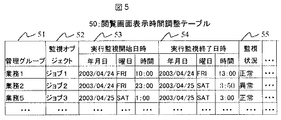
図5は本実施形態の閲覧画面表示時間調整テーブルのデータ例を示す図である。図5に示す様にデータ保存部10に格納される閲覧画面表示時間調整テーブル50は、監視の対象を纏めて管理する際の名称を示す管理グループ51と、監視の対象となっているジョブを示す監視オブジェクト52と、そのジョブの監視を開始する日時を示す実行監視開始日時53と、そのジョブの監視を終了する日時を示す実行監視終了日時54と、そのジョブの状況を示す監視状況55で構成されている。
【0040】
次に、本実施形態の業務運用監視システムにおいて、計算機上で実行されるジョブの運用監視を行う際に、監視状況の閲覧が行われる閲覧時間帯に実行予定となっているジョブを選択してそのジョブの監視状況を表示する処理について説明する。
【0041】
ジョブ実行部5のスケジュール格納部6は、ジョブ実行部5によって実行されるジョブの実行スケジュールをスケジュール格納テーブル20へ格納して管理しており、管理者からのスケジュールの変更内容が入力された場合には、その変更内容に従ってスケジュール格納テーブル20を更新する。
【0042】
また実行実績値格納部7は、ジョブ実行部5によってジョブが起動されるとその実行状態に応じて実行実績時間32等の実績値を実行実績値格納テーブル30に格納する。
【0043】
ジョブ実行部5のイベント発行部8は、スケジュール格納テーブル20及び実行実績値格納テーブル30の更新状況を監視し、テーブルの内容が変更された場合にはテーブルの変更が行われたことをイベントを統合監視部2に通知する。
【0044】
統合監視部2のイベント受信部15は、イベント発行部8より通知されたイベントを受け取ると、そのイベントで示される変更内容を監視項目取得部11へ通知する。
【0045】
監視項目取得部11では、前記通知された変更内容中のジョブ名を監視オブジェクト52として閲覧画面表示時間調整テーブル50のレコードにレコードを追加する。その際、複数の監視オブジェクト52を所定の規則で纏める為の管理グループ51を設定してグループ化するものとしても良い。
【0046】
例えば、サーバ毎に纏めるという場合には、各ジョブの関連項目25にホスト名が記載されているので、それを用いてグループ化できるし、他の要素でも、インデックスを付与しておくことで容易にグループ化できる。グループ化するタイミングは項目収集と同時でも良いし、運用開始後であっても良く、また管理グループ自身を階層化しても良い。
【0047】
グループ化することで、監視画面をツリー構成で閲覧する場合には、階層が深くなるが纏まって見易くなる。また、監視画面を地図上で表示する場合には、監視オブジェクト単位でも表示することができるが、管理グループで纏めてあると視覚的に判り易くなる。
【0048】
次に監視項目取得部11は、前記通知された変更内容から実行開始予定日時23や実行実績時間32を読み出した後、実績値計算部12により、前記読み出した実行実績時間32と、そのジョブについて過去のイベントにより通知されている実行実績時間32との総和から平均値を算出して当該ジョブの実行時間最適値を求める。
【0049】
そして、前記読み出した実行開始予定日時23を実行監視開始日時53に格納し、実行開始予定日時23に前記求めた実行時間最適値を加えて予想終了日時を算出して実行監視終了日時54に設定する。ここで、前記読み出した実行開始予定日時23から所定時間を引いた日時を実行監視開始日時53に格納し、前記予想終了日時に所定時間を加えた日時を実行監視終了日時54に設定するものとしても良い。
【0050】
前記の様に実行監視開始日時53を実行開始予定日時23となる前の日時に設定することにより、そのジョブの実行開始前にポイント監視部4からの情報を収集してCPU等のリソースで異常が発生していないか等を確認することができる。また、実行監視終了日時54を予想終了日時以後の日時に設定することにより、予想終了日時を超えて実行が継続された場合でも監視を継続することができる。
【0051】
一方、統合監視画面閲覧部3の閲覧日時設定部17は、監視状況の閲覧を開始する日時を示す閲覧開始日時及び閲覧を終了する日時を示す閲覧終了日時の指定を閲覧担当者から受け付けた後、その受け付けた閲覧開始日時及び閲覧終了日時と、監視状況の閲覧が行われる閲覧場所、すなわち統合監視画面閲覧部3の設置されている国や地域を示す情報を統合監視部2へ送信する。
【0052】
例えば閲覧開始日時及び閲覧終了日時の指定として、5月15日の9:00から17:00までという入力が行われると、監視画面表示部18では、5月15日の9:00から17:00に実行が開始されるか若しくは実行中の業務ジョブのみを表示する。現在の監視状況を閲覧する場合には少なくとも閲覧開始日時に現在時刻を指定するものとし、指定された日時が過去の日時である場合には過去に実行された業務ジョブの監視結果を表示し、指定された日時が未来の日時である場合には、これから実行される業務ジョブとその業務ジョブに影響する障害情報を表示するものとする。また本実施形態では閲覧開始日時及び閲覧終了日時の指定が無い場合には全業務運用監視画面の閲覧処理を行うものとする。
【0053】
統合監視部2では、前記送信された情報を受信すると、閲覧日時補正部14により、監視状況の閲覧が行われる閲覧場所とジョブの実行が行われる実行場所との間の時差に応じて前記日時の情報を補正する処理を行う。
【0054】
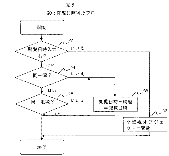
図6は本実施形態の閲覧日時補正処理の処理手順を示すフローチャートである。図6では閲覧日時補正部14で閲覧日時を補正する処理の流れを表しており、閲覧担当者が閲覧日時設定部17で閲覧したい期間を入力し、実行場所と閲覧場所に時差がある場合に時差を補正する処理を行う。
【0055】
ステップ61で閲覧日時補正部14は、統合監視画面閲覧部3から送信された情報の内容を参照して閲覧開始日時及び閲覧終了日時の設定が行われているかどうかを調べ、閲覧開始日時及び閲覧終了日時の設定が行われていない場合にはステップ62で全監視オブジェクトを閲覧対象として登録し、閲覧開始日時及び閲覧終了日時の設定が行われている場合にはステップ63へ進む。
【0056】
ステップ63では、統合監視画面閲覧部3から送信された情報の内容を参照して閲覧場所を読み出した後、スケジュール格納テーブル20中の実行場所24の内容と比較して閲覧場所の国名と実行場所24の国名が同一であるかを判定し、同一国である場合にはステップ64へ進み、同一国ではない場合にはステップ65へ進む。
【0057】
ステップ64では、統合監視画面閲覧部3から送信された閲覧場所とスケジュール格納テーブル20中の実行場所24の内容と比較して閲覧場所の地域名と実行場所24の地域名が同一であるかを判定し、同一地域である場合には処理を終了し、同一地域ではない場合にはステップ65へ進む。
【0058】
ステップ65では、前記閲覧場所の国及び地域におけるグリニッジ標準時に対する時差と、前記実行場所の国及び地域におけるグリニッジ標準時に対する時差とから、前記閲覧場所と前記実行場所との間の時差を算出した後、閲覧開始日時及び閲覧終了日時から前記算出した時差を引いて補正後の閲覧開始日時及び閲覧終了日時を求めた後、その求めた補正後の閲覧開始日時及び閲覧終了日時を前記実行場所のジョブ名21と対応付けてメモリ上に格納しておく。
【0059】
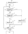
次に統合監視部2の閲覧画面表示時間調整部13は、閲覧開始日時及び閲覧終了日時で表される閲覧時間帯と、前記設定された実行監視開始日時53及び実行監視終了日時54で表される監視時間帯との間に重なる部分が存在するかどうかを調べて閲覧対象のジョブを選択する処理を行う。
【0060】
図7は本実施形態の閲覧対象選択処理の処理手順を示すフローチャートである。ステップ71で閲覧画面表示時間調整部13は、閲覧画面表示時間調整テーブル50を参照して実行監視開始日時53と統合監視画面閲覧部3から送信された閲覧終了日時とを比較し、実行監視開始日時53の値が閲覧終了日時の値以下である場合にはステップ72へ進み、実行監視開始日時53の値が閲覧終了日時の値よりも大きい場合にはステップ74へ進む。ここで、その監視オブジェクト52と一致するジョブ名21に対応した補正後の閲覧終了日時がメモリ上に格納されている場合にはその補正後の値を用いるものとする。
【0061】
ステップ72では、閲覧画面表示時間調整テーブル50を参照して実行監視終了日時54と統合監視画面閲覧部3から送信された閲覧開始日時とを比較し、実行監視終了日時54の値が閲覧開始日時の値以上である場合にはステップ73へ進み、実行監視終了日時54の値が閲覧開始日時の値よりも小さい場合にはステップ74へ進む。ここで、その監視オブジェクト52と一致するジョブ名21に対応した補正後の閲覧開始日時がメモリ上に格納されている場合にはその補正後の値を用いるものとする。
【0062】
ステップ73では、その監視オブジェクト52を閲覧対象として選択し、その監視オブジェクト52中のジョブ名をメモリ上に格納する。またステップ74では、その監視オブジェクト52を非閲覧対象に設定し、その監視オブジェクト52中のジョブ名がメモリ上に格納されているかどうかを調べて、メモリ上に格納されている場合にはそのジョブ名をメモリ上から削除する。
【0063】
ステップ75では、全監視オブジェクトに対して前記日時の比較を行ったかどうかを調べ、まだ全監視オブジェクトについての比較を完了していない場合にはステップ71へ戻って処理を続行し、全監視オブジェクトについての比較を完了した場合にはこの処理を終了する。
【0064】
前記の様にして閲覧対象の選択が行われると統合監視画面データ生成部16は、閲覧画面表示時間調整部13で閲覧対象として選択されたジョブのジョブ名をメモリ上から読み出した後、そのジョブ名に対応する監視オブジェクト52の監視状況55や当該ジョブに関する他の情報をデータ保存部10から取得し、そのジョブの状態を表示する為の監視画面データを生成して統合監視画面閲覧部3へ送信する。
【0065】
統合監視画面閲覧部3の監視画面表示部18は、統合監視画面データ生成部16で生成された監視データを統合監視部2から受信し、業務の運用状態を監視する為の監視画面を統合監視画面閲覧部3のディスプレイ装置へ表示する処理を行う。
【0066】
また統合監視画面データ生成部16は、監視画面データを生成した後にイベント受信部15により重要度43の変更やジョブの終了結果等のプライオリティの高いイベントを受信した場合には、その内容に従って監視画面データを生成して統合監視画面閲覧部3へ送信することにより、監視画面を随時更新して常に最新状態を維持する様に処理を行うものとする。
【0067】
その際、一旦度表示したジョブであっても正常に終了したものについては随時削除を行うものとするが、異常終了した場合には実行監視終了日時54を経過した後でも削除せずに閲覧対象として残すものとする。
【0068】
前記の処理では、ジョブの実行実績として得られた実行実績時間32の平均値を実行時間として実行監視開始日時53及び実行監視終了日時54の設定を行っているが、実行実績時間32とそのジョブの実行時の稼働率との関係からその稼働率での実行に要する時間を示す実行時間最適値を算出してデータ保存部10のデータ保存テーブルへ格納しておき、その実行時間最適値を実行時間として実行監視開始日時53及び実行監視終了日時54の設定を行う様にしても良い。
【0069】
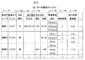
図8は本実施形態のデータ保存テーブルのデータ例を示す図である。図8に示す様にデータ保存テーブル80は、監視の対象を纏めて管理する際の名称を示す管理グループ81と、監視の対象となっているジョブを示す監視オブジェクト82と、曜日毎に実行される週次業務、毎日実行される日次業務、特定の指定日時に実行される業務等のスケジュールの種類を保存する日時種別83と、そのジョブの実行が開始される日時を格納する実行開始予定日時84と、ポイント監視部4での監視されているリソース等の内でジョブの実行に影響するものを示す関連監視項目85と、稼働率を数段階のレベルに分けた稼働指数86と、稼働率を考慮して算出した実行時間である実行時間最適値87で構成されている。
【0070】
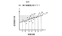
図9は本実施形態の実行実績値分析グラフの一例を示す図である。複数のジョブが実行され、あるジョブに対するリソースの稼働率が増加して稼働指数が増加するとそのジョブの実行実績時間は図9に示す様に増加すると考えられることから、稼働指数と実行実績時間との関係を最小自乗法により直線で近似し、各稼働指数における実行時間最適値の算出を行う。
【0071】
まず監視項目取得部11は、スケジュール格納テーブル20の関連項目25をキーにして監視項目格納テーブル40の監視対象41を検索する。テーブルではジョブを実行するホストの名称をキーとして関連項目25と監視対象41とを対応付けているが、対応が一意に決まるものであればどの様な内容であっても良い。関連項目25と監視対象41との対応が付いたら、そのレコード中の稼働率45を読み出して稼働指数86としてデータ保存テーブル80に格納する。稼働率45の値は時間帯によって変動する場合が多い為、所定時間毎か変動する毎に稼働率45を読み出してデータ保存テーブル80への格納を行うものとする。また、ポイント監視部4が存在しない場合、つまり関連項目25と対応する監視対象41のポイント監視が行われていない為に監視状況が判らない場合には、データ保存テーブル80中の稼働指数は「0」であるものとする。
【0072】
監視項目取得部11で全ての関連項目25と監視対象41の対応付けが終わったら、実績値計算部12は、稼働指数86を基に実行時間最適値87を算出する。
【0073】
図10は本実施形態の実行時間最適値算出処理の処理手順を示すフローチャートである。まずステップ101で実績値計算部12は、実行実績時間32にバラツキがあるかどうかを判定する。例えば、最短実行実績時間と最長実行実績時間の差が全実行実績時間の0.01%以内であるかどうかを算出し、0.01%以内に実行実績時間差が収まった場合、実行実績時間32にバラツキが無いものとしてステップ102へ進み、最も実行実績時間が集中している時間を実行時間最適値87とし、その際には稼働指数86は「0」として考慮しないものとする。
【0074】
実行実績時間32にバラツキがある場合にはステップ103へ進み、稼働率45を参照する。ポイント監視を行っていなければ稼働率45のデータが無いのでステップ104で稼働指数86を「0」としてステップ107へ進み、全ての実行実績時間32の実測値を加算して実測値の数で除算した平均値を実行時間最適値87とする。
【0075】
また、ポイント監視を行っていてもステップ105で稼働率45にバラツキが無い場合にはステップ106へ進み、当該稼働率を数段階のレベルに分けた稼働指数86を求めた後、ステップ107で全ての実行実績時間32の実測値を加算して実測値の数で除算した平均値を実行時間最適値87とする。
【0076】
ステップ105で稼働率45にバラツキがある場合、ジョブを実行する上で各種リソース等の負荷に差があるということになるのでステップ108へ進み、実行実績時間をy、稼働指数をxとして最小自乗法により、実行実績時間と稼働指数の残差平方和を最小とする実行時間最適値を求める。
【0077】
すなわち、実行実績時間yが以下の数1で表されるものとし、実行実績時間の実測数をnとすると、数2を満たすaとbを求めることにより実行時間最適値を得る。
【0078】
【数1】
y=a+bx
【0079】
【数2】
【0080】
前記の様にして実績値計算部12により実行時間最適値87が算出されると、監視項目取得部11は、実行監視開始日時53と実行監視終了日時54を、例えば以下の数3により決定する。
【0081】
【数3】
実行監視開始日時=実行開始予定日時−稼働指数×c−異常終了回数×d、
実行監視終了日時=実行開始予定日時+実行時間最適値+稼働指数×f+異常終了回数×g
但し、時間係数c、d、f及びgは任意の時間であるものとする。
【0082】
前記の様に本実施形態では、リソースの稼働率を示す稼働指数の値やジョブの異常終了の回数等、業務に影響を及ぼす指数によって監視時間を広げ、実行実績値を考慮した業務スケジュールに基づいて、閲覧日時で閲覧対象をフィルタリングすることができる。時間係数は管理者が予めまたは随時設定できる為、全く余計な幅を持たせずに、実行予定時間だけでフィルタリングしたい場合には時間係数を全て0時間とすれば良い。
【0083】
また、ジョブが異常終了していないか監視したいときは、ジョブ実行終了の後ろに幅を持たせる為の実行監視終了日時を設定し、ジョブ実行開始予定日時の前に障害が発生していないか確認したい場合には、実行監視開始日時を早めに設定するといった使用方法が挙げられる。
【0084】
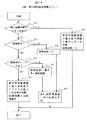
図11は従来の運用監視画面におけるツリー表示の一例を示す図である。図11では、従来技術若しくは本実施形態の閲覧日時設定部17で閲覧開始日時又は閲覧終了日時を設定しなかった場合に、運用監視画面を管理者の指向に応じてツリー表示した場合の表示例を表しており、様々な監視項目を拠点毎に業務1、業務2という名前でグルーピングしたものを全て階層構造で表示したもので、業務2に障害等が発生しており、当該監視項目が点滅若しくは赤色等で表示されていることを示している。
【0085】
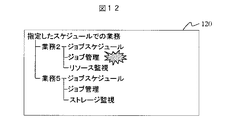
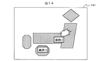
なお図11から図14では図の星印の箇所で障害発生しており、当該監視項目が点滅若しくは赤色等で表示されているものとするが、必ずしも点滅していなくても良く、記号や色等、容易に認識できる形式になっていれば良いものとする。
【0086】
図12は本実施形態の運用監視画面におけるツリー表示の一例を示す図である。図12では、閲覧日時設定部17で閲覧開始日時及び閲覧終了日時を設定した場合に、監視画面表示部18で、業務スケジュールに連動した運用監視画面を管理者の指向に応じてツリー表示した場合の表示例を表しており、閲覧日時設定部17で設定した閲覧時間帯に実行予定となっている業務2と業務5のみが表示され、障害が発生している業務2のみが点滅若しくは赤色等で表示されている状態を示している。
【0087】
図13は従来の運用監視画面におけるマップ表示の一例を示す図である。図13では、従来技術若しくは本実施形態による閲覧日時設定部17で閲覧開始日時及び閲覧終了日時を設定しなかった場合に、監視画面表示部18で、運用監視画面をマップ表示した場合の表示例を表しており、様々な監視項目を拠点毎に業務1、業務2という名前でグルーピングしたものを地図に載せて表示したもので、業務2に障害等が発生しており、当該監視項目が点滅若しくは赤色等で表示されていることを示している。
【0088】
図14は本実施形態における運用監視画面のマップ表示の一例を示す図である。図14では、閲覧日時設定部17で閲覧開始日時及び閲覧終了日時を設定した場合に、監視画面表示部18で、業務スケジュールに連動した運用監視画面をマップ表示した場合の表示例を表しており、閲覧日時設定部17で設定した閲覧時間帯に実行予定となっている業務2と業務5のみが表示され、障害が発生している業務2のみが点滅若しくは赤色等で表示されていることを表している。
【0089】
前記の様に本実施形態では、業務運用監視画面を閲覧する者が要求する閲覧時間帯における業務の情報のみが表示される為、閲覧者の閲覧場所や業務経験、業務や障害の数に関係無く、効率的な業務運用監視が可能となる。
【0090】
以上説明した様に本実施形態の運用監視システムによれば、監視状況の閲覧が行われる時間帯に実行予定となっているジョブを選択してそのジョブの監視状況を表示するので、計算機上で実行されるジョブの運用監視及び障害対応を迅速且つ効率的に行うことが可能である。
【0091】
【発明の効果】
本発明によれば監視状況の閲覧が行われる時間帯に実行予定となっているジョブを選択してそのジョブの監視状況を表示するので、計算機上で実行されるジョブの運用監視及び障害対応を迅速且つ効率的に行うことが可能である。
【図面の簡単な説明】
【図1】本実施形態の業務運用監視システムの全体構成を示す図である。
【図2】本実施形態のスケジュール格納テーブルのデータ例を示す図である。
【図3】本実施形態の実行実績値格納テーブルのデータ例を示す図である。
【図4】本実施形態の監視項目格納テーブルのデータ例を示す図である。
【図5】本実施形態の閲覧画面表示時間調整テーブルのデータ例を示す図である。
【図6】本実施形態の閲覧日時補正処理の処理手順を示すフローチャートである。
【図7】本実施形態の閲覧対象選択処理の処理手順を示すフローチャートである。
【図8】本実施形態のデータ保存テーブルのデータ例を示す図である。
【図9】本実施形態の実行実績値分析グラフの一例を示す図である。
【図10】本実施形態の実行時間最適値算出処理の処理手順を示すフローチャートである。
【図11】従来の運用監視画面におけるツリー表示の一例を示す図である。
【図12】本実施形態の運用監視画面におけるツリー表示の一例を示す図である。
【図13】従来の運用監視画面におけるマップ表示の一例を示す図である。
【図14】本実施形態のおける運用監視画面のマップ表示の一例を示す図である。
【符号の説明】
1…ネットワーク、10…データ保存部、2…統合監視部、3…統合監視画面閲覧部、4…ポイント監視部、5…ジョブ実行部、6…スケジュール格納部、7…実行実績値格納部、8…イベント発行部、9…監視内容格納部、11…監視項目取得部、12…実績値計算部、13…閲覧画面表示時間調整部、14…閲覧日時補正部、15…イベント受信部、16…統合監視画面データ生成部、17…閲覧日時設定部、18…監視画面表示部、20…スケジュール格納テーブル、21…ジョブ名、22…日時種別、23…実行開始予定日時、24…実行場所、25…関連項目、30…実行実績値格納テーブル、31…ジョブ名、32…実行実績時間、33…終了状態、34…実行開始日時、35…実行終了日時、40…監視項目格納テーブル、41…監視対象、42…監視対象詳細、43…重要度、44…場所、45…稼働率、46…監視日時、50…閲覧画面表示時間調整テーブル、51…管理グループ、52…監視オブジェクト、53…実行監視開始日時、54…実行監視終了日時、55…監視状況、60…閲覧日時補正フロー、70…閲覧画面表示時間比較フロー、80…データ保存テーブル、81…管理グループ、82…監視オブジェクト、83…日時種別、84…実行開始予定日時、85…関連監視項目、86…稼働指数、87…実行時間最適値、90…実行実績値分析グラフ、91…実行実績時間測定値、92…実行時間最適値、93…実行実績値分析直線、100…実行時間最適値算出フロー、110…ツリー表示の監視画面、120…ツリー表示の監視画面、130…マップ表示の監視画面、140…マップ表示の監視画面。[0001]
TECHNICAL FIELD OF THE INVENTION
The present invention relates to an operation monitoring system that monitors the operation of a job executed on a computer, and is particularly effective when applied to an operation monitoring system that efficiently displays a monitoring item and a failure content on a business operation monitoring screen and performs operation monitoring. Technology.
[0002]
[Prior art]
Conventionally, when monitoring the operation of a job executed on a computer, information indicating the status of the job to be executed or the job being executed is collected and displayed on the monitoring screen, and the job being executed may be When the processing ends abnormally, the display method of the job in which the error has occurred or the job to be executed which is affected by the job is changed to notify the monitoring staff of the occurrence of the error.
[0003]
For example, in performing network monitoring, when the monitoring status changes, the current status of the monitoring target and the previous status are represented by different types of marks, and the current status is displayed and the previous status is displayed. There is known a method in which a mark displaying is alternately switched at a predetermined cycle recognizable to the naked eye and dynamically displayed (for example, see Patent Document 1).
[0004]
[Patent Document 1]
JP-A-9-62542
[0005]
[Problems to be solved by the invention]
In the prior art, the status of a job that can be executed normally or a job that is executed only once a year or once a month is also displayed on the monitor screen, so that a complicated or huge number of jobs can be monitored. In this case, if all the job statuses are displayed on the monitoring screen, it is difficult to efficiently monitor an enormous number of jobs.
[0006]
SUMMARY OF THE INVENTION It is an object of the present invention to solve the above-mentioned problems and to provide a technique capable of quickly and efficiently monitoring the operation of a job executed on a computer and coping with a failure.
[0007]
[Means for Solving the Problems]
According to the present invention, in an operation monitoring system that monitors the operation of a job executed on a computer, a job scheduled to be executed during a time period when the monitoring status is browsed is selected and the monitoring status of the job is displayed. Things.
[0008]
In the operation monitoring system of the present invention, the schedule information including the scheduled execution start date and time indicating the scheduled start date and time of the job is changed (including addition or deletion), and the actual execution time required for executing the job is included. When the execution result value information is changed (including addition or deletion), an event indicating the content is generated by the job execution unit and notified to the integrated monitoring unit.
[0009]
The integrated monitoring unit receives the notified event, obtains schedule information indicating a job execution schedule, and the like, and monitors the job using the actual execution time of the job from the scheduled start date and time of the job. An execution monitoring start date and time indicating a start date and time and an execution monitoring end date and time indicating a monitoring end date and time are set.
[0010]
At this time, a predetermined time is set according to information that may affect the execution of the job, such as the operation rate or the number of abnormal terminations of the computer during the execution of the job. The execution monitoring start date and time and the execution monitoring end date and time may be set by adding the predetermined time before and after the time zone.
[0011]
In addition, the average value of the execution time obtained as the execution result of the job is set as the execution time optimum value, or the time required for the execution at the operation rate is determined from the relationship between the execution time and the operation rate at the time of executing the job. And the execution monitoring start date and time and the execution monitoring end date and time may be set.
[0012]
Next, the integrated monitoring screen browsing unit accepts the specification of the browsing start date and time indicating the monitoring start date and time and the browsing end date and time indicating the browsing end date and time. Then, the information of the browsing location where the monitoring status is browsed, that is, the information indicating the installation location of the integrated monitoring screen browsing unit is transmitted to the integrated monitoring unit.
[0013]
In the integrated monitoring unit, upon receiving the transmitted information, a browsing time zone represented by a browsing start date and time and a browsing end date and time, and a monitoring time zone represented by the set execution monitoring start date and time and the execution monitoring end date and time are displayed. Are compared, and if there is an overlapping portion between them, the job for which the execution monitoring start date and time and the execution monitoring end date and time are set is selected as a viewing target.
[0014]
At that time, compare the browsing location where the monitoring status is browsed and the execution location where the job is executed and check if there is a time difference between them, and if there is a time difference, correct the date and time information To select the browsing target.
[0015]
Then, after generating monitoring screen data for displaying the monitoring status of the job selected as the browsing target, the generated monitoring screen data is transmitted to the integrated monitoring screen browsing unit. A monitoring screen is displayed on a display device based on the screen data.
[0016]
As described above, in the operation monitoring system of the present invention, the administrator who wants to monitor the operation of the business sets a relatively short period such as one hour or one day as the browsing date and time so that the set browsing time period can be set. The number of tasks monitored by the administrator is limited by extracting business jobs that are scheduled to be executed and generating monitoring screen data that displays only the extracted tasks and information such as failures related to the tasks. As a result, trouble can be quickly and efficiently handled.
[0017]
As described above, according to the operation monitoring system of the present invention, a job scheduled to be executed during a period in which the monitoring status is browsed is selected and the monitoring status of the job is displayed. It is possible to quickly and efficiently monitor the operation of a job and respond to a failure.
[0018]
BEST MODE FOR CARRYING OUT THE INVENTION
An operation monitoring system according to an embodiment for monitoring the operation of a job executed on a computer will be described below.
[0019]
FIG. 1 is a diagram showing an overall configuration of a business operation monitoring system of the present embodiment. As shown in FIG. 1, the business operation monitoring system according to the present embodiment includes an integrated
[0020]
The integrated
[0021]
The
[0022]
The
[0023]
The
[0024]
When the contents of the schedule storage table 20, the execution result value storage table 30, and the monitoring item storage table 40 are changed, the
[0025]
The monitoring
[0026]
The monitoring
[0027]
The performance value calculation unit 12 calculates the execution time used for setting the execution monitoring start date and time and the execution monitoring end date and time based on the information such as the actual execution time and the operation rate acquired by the monitoring
[0028]
The browsing screen display
[0029]
The viewing
[0030]
The integrated monitoring screen
[0031]
The browsing date and
[0032]
The monitoring
[0033]
The business operation monitoring system includes an integrated
[0034]
FIG. 2 is a diagram illustrating a data example of the schedule storage table according to the present embodiment. As shown in FIG. 2, the schedule storage table 20 managed by the
[0035]
FIG. 3 is a diagram illustrating an example of data in the execution result value storage table according to the present embodiment. As shown in FIG. 3, the execution result value storage table 30 managed by the execution result
[0036]
FIG. 4 is a diagram illustrating a data example of the monitoring item storage table according to the present embodiment. As shown in FIG. 4, a monitoring item storage table 40 managed by the monitoring
[0037]
In addition, by setting in advance a threshold value indicating what state the event is issued in, the event can be notified to the integrated
[0038]
Further, the
[0039]
FIG. 5 is a diagram illustrating an example of data of the browsing screen display time adjustment table according to the present embodiment. As illustrated in FIG. 5, the browsing screen display time adjustment table 50 stored in the
[0040]
Next, in the business operation monitoring system according to the present embodiment, when monitoring the operation of a job executed on a computer, the user selects a job scheduled to be executed during a viewing time period during which the monitoring status is viewed. The process of displaying the monitoring status of the job will be described.
[0041]
The
[0042]
When the job is started by the
[0043]
The
[0044]
When receiving the event notified from the
[0045]
The monitoring
[0046]
For example, in the case of grouping for each server, since the host name is described in the
[0047]
By grouping, when browsing the monitoring screens in a tree structure, the hierarchy becomes deeper but easier to see. Further, when the monitoring screen is displayed on a map, it can be displayed in monitoring object units, but it is easier to visually recognize if the monitoring screens are organized in a management group.
[0048]
Next, the monitoring
[0049]
Then, the read scheduled execution start date and time 23 is stored in the execution monitoring start date and
[0050]
By setting the execution monitoring start date and
[0051]
On the other hand, after the browsing date and
[0052]
For example, when an input of 9:00 to 17:00 on May 15 is made as the designation of the browsing start date and time and the browsing end date and time, the monitoring
[0053]
When the integrated
[0054]
FIG. 6 is a flowchart showing the processing procedure of the browsing date and time correction processing of the present embodiment. FIG. 6 shows a flow of a process of correcting the viewing date and time by the viewing date and
[0055]
In
[0056]
In
[0057]
In
[0058]
In
[0059]
Next, the browsing screen display
[0060]
FIG. 7 is a flowchart illustrating a processing procedure of the browsing target selection processing according to the present embodiment. In step 71, the viewing screen display
[0061]
In
[0062]
In
[0063]
In
[0064]
When the browsing target is selected as described above, the integrated monitoring screen
[0065]
The monitoring
[0066]
When the
[0067]
At this time, even if the job has been displayed once, it should be deleted at any time if it ended normally, but if it ended abnormally, it will not be deleted even after the execution monitoring end date and
[0068]
In the above-described processing, the execution monitoring start date and
[0069]
FIG. 8 is a diagram illustrating a data example of the data storage table according to the present embodiment. As shown in FIG. 8, the data storage table 80 includes a
[0070]
FIG. 9 is a diagram illustrating an example of the execution result value analysis graph of the present embodiment. When a plurality of jobs are executed and the operation rate of the resource for a certain job increases and the operation index increases, the actual execution time of the job is considered to increase as shown in FIG. 9. Is approximated by a straight line by the method of least squares, and an optimum execution time value for each operation index is calculated.
[0071]
First, the monitoring
[0072]
When all the
[0073]
FIG. 10 is a flowchart illustrating a processing procedure of the execution time optimum value calculation processing according to the present embodiment. First, in
[0074]
If there is a variation in the actual execution time 32, the process proceeds to step 103, and the operation rate 45 is referred to. If point monitoring is not performed, there is no data of the operation rate 45, so the
[0075]
Also, even if the point monitoring is performed, if there is no variation in the operation rate 45 in
[0076]
If there is a variation in the operation rate 45 in
[0077]
That is, assuming that the actual execution time y is represented by the
[0078]
(Equation 1)
y = a + bx
[0079]
(Equation 2)
[0080]
When the execution time
[0081]
[Equation 3]
Execution monitoring start date and time = scheduled execution start date and time-operation index x c-abnormal end count x d
Execution monitoring end date and time = Scheduled start date and time of execution + Optimum execution time + Operation index x f + Number of abnormal end times x g
However, the time coefficients c, d, f, and g are arbitrary times.
[0082]
As described above, in the present embodiment, the monitoring time is extended by an index that affects the operation, such as the value of the operation index indicating the resource operation rate or the number of abnormal terminations of the job, and based on the operation schedule in consideration of the actual execution value. Thus, the browsing target can be filtered by the browsing date and time. The time coefficient can be set in advance by the administrator or at any time. Therefore, if it is desired to filter only the scheduled execution time without giving any extra width, all time coefficients may be set to 0 hours.
[0083]
Also, if you want to monitor whether a job has terminated abnormally, set the execution monitoring end date and time to give a margin after the job execution end, and check whether a failure has occurred before the scheduled job execution start date and time. When the user wants to confirm, there is a usage method such as setting the execution monitoring start date and time earlier.
[0084]
FIG. 11 is a diagram showing an example of a tree display on a conventional operation monitoring screen. FIG. 11 shows a display example in which the operation monitoring screen is displayed in a tree according to the orientation of the administrator when the browsing start date and time or the browsing end date and time are not set in the browsing date and
[0085]
In FIGS. 11 to 14, it is assumed that a failure has occurred at the location of the star in the figure, and the monitoring item is blinking or displayed in red or the like. For example, the format should be such that it can be easily recognized.
[0086]
FIG. 12 is a diagram illustrating an example of a tree display on the operation monitoring screen according to the present embodiment. In FIG. 12, when the browsing start date and time and the browsing end date and time are set in the browsing date and
[0087]
FIG. 13 is a diagram showing an example of a map display on a conventional operation monitoring screen. FIG. 13 shows a display example in which the operation monitor screen is displayed on the monitor
[0088]
FIG. 14 is a diagram illustrating an example of a map display of the operation monitoring screen according to the present embodiment. FIG. 14 illustrates a display example in a case where the browsing start date and time and the browsing end date and time are set by the browsing date and
[0089]
As described above, in the present embodiment, since only the information on the work in the browsing time period requested by the person who views the business operation monitoring screen is displayed, the information related to the browsing location and work experience of the viewer, the number of work and obstacles And efficient business operation monitoring becomes possible.
[0090]
As described above, according to the operation monitoring system of the present embodiment, a job scheduled to be executed during a period in which the monitoring status is browsed is selected and the monitoring status of the job is displayed. It is possible to quickly and efficiently monitor the operation of an executed job and respond to a failure.
[0091]
【The invention's effect】
According to the present invention, a job scheduled to be executed during a time period in which the monitoring status is browsed is selected and the monitoring status of the job is displayed, so that the operation monitoring and failure handling of the job executed on the computer can be performed. It can be done quickly and efficiently.
[Brief description of the drawings]
FIG. 1 is a diagram illustrating an overall configuration of a business operation monitoring system according to an embodiment.
FIG. 2 is a diagram illustrating a data example of a schedule storage table according to the embodiment;
FIG. 3 is a diagram illustrating a data example of an execution result value storage table according to the embodiment;
FIG. 4 is a diagram illustrating a data example of a monitoring item storage table according to the embodiment;
FIG. 5 is a diagram illustrating a data example of a browsing screen display time adjustment table according to the embodiment;
FIG. 6 is a flowchart illustrating a processing procedure of a viewing date correction process according to the embodiment.
FIG. 7 is a flowchart illustrating a processing procedure of a browsing target selection process according to the embodiment.
FIG. 8 is a diagram illustrating a data example of a data storage table according to the present embodiment.
FIG. 9 is a diagram illustrating an example of an execution result value analysis graph according to the present embodiment.
FIG. 10 is a flowchart illustrating a processing procedure of an execution time optimum value calculation process according to the embodiment;
FIG. 11 is a diagram showing an example of a tree display on a conventional operation monitoring screen.
FIG. 12 is a diagram illustrating an example of a tree display on an operation monitoring screen according to the present embodiment.
FIG. 13 is a diagram showing an example of a map display on a conventional operation monitoring screen.
FIG. 14 is a diagram illustrating an example of a map display of an operation monitoring screen according to the present embodiment.
[Explanation of symbols]
DESCRIPTION OF
Claims (10)
ジョブの実行予定を示すスケジュール情報を取得して、そのジョブの監視を開始する日時を示す実行監視開始日時及び監視を終了する日時を示す実行監視終了日時を設定するステップと、
監視状況の閲覧を開始する日時を示す閲覧開始日時及び閲覧を終了する日時を示す閲覧終了日時で表される閲覧時間帯と、前記設定された実行監視開始日時及び実行監視終了日時で表される監視時間帯との間に重なる部分が存在する場合に、その実行監視開始日時及び実行監視終了日時が設定されているジョブを閲覧対象として選択するステップと、
前記閲覧対象として選択されたジョブの監視状況を表示する為の監視画面データを生成するステップとを有することを特徴とする運用監視方法。In an operation monitoring method for monitoring the operation of a job executed on a computer,
Acquiring schedule information indicating a job execution schedule, and setting an execution monitoring start date and time indicating a date and time to start monitoring the job and an execution monitoring end date and time indicating a date and time to end monitoring;
A browsing time zone represented by a browsing start date and time indicating a date and time when browsing of the monitoring status is started and a browsing end date and time indicating a browsing end date and time, and represented by the set execution monitoring start date and time and the execution monitoring end date and time. When there is an overlapping portion between the monitoring time zone and the execution monitoring start date and time and the execution monitoring end date and time are selected as a browsing target,
Generating monitoring screen data for displaying a monitoring status of the job selected as the browsing target.
ジョブの実行予定を示すスケジュール情報を取得して、そのジョブの監視を開始する日時を示す実行監視開始日時及び監視を終了する日時を示す実行監視終了日時を設定する監視項目取得部と、
監視状況の閲覧を開始する日時を示す閲覧開始日時及び閲覧を終了する日時を示す閲覧終了日時で表される閲覧時間帯と、前記設定された実行監視開始日時及び実行監視終了日時で表される監視時間帯との間に重なる部分が存在する場合に、その実行監視開始日時及び実行監視終了日時が設定されているジョブを閲覧対象として選択する閲覧画面表示時間調整部と、
前記閲覧対象として選択されたジョブの監視状況を表示する為の監視画面データを生成する統合監視画面データ生成部とを備えることを特徴とする運用監視システム。In an operation monitoring system that monitors the operation of jobs executed on computers,
A monitoring item acquisition unit that acquires schedule information indicating a job execution schedule, and sets an execution monitoring start date and time indicating a date and time when monitoring of the job is started and an execution monitoring end date and time indicating a date and time when monitoring is ended;
A browsing time zone represented by a browsing start date and time indicating a date and time when browsing of the monitoring status is started and a browsing end date and time indicating a browsing end date and time, and represented by the set execution monitoring start date and time and the execution monitoring end date and time. A browsing screen display time adjustment unit that selects, as a browsing target, a job for which the execution monitoring start date and time and the execution monitoring end date and time are set when there is an overlapping part between the monitoring time zone;
An operation monitoring system, comprising: an integrated monitoring screen data generation unit that generates monitoring screen data for displaying a monitoring status of the job selected as the browsing target.
ジョブの実行予定を示すスケジュール情報を取得して、そのジョブの監視を開始する日時を示す実行監視開始日時及び監視を終了する日時を示す実行監視終了日時を設定する監視項目取得部と、
監視状況の閲覧を開始する日時を示す閲覧開始日時及び閲覧を終了する日時を示す閲覧終了日時で表される閲覧時間帯と、前記設定された実行監視開始日時及び実行監視終了日時で表される監視時間帯との間に重なる部分が存在する場合に、その実行監視開始日時及び実行監視終了日時が設定されているジョブを閲覧対象として選択する閲覧画面表示時間調整部と、
前記閲覧対象として選択されたジョブの監視状況を表示する為の監視画面データを生成する統合監視画面データ生成部としてコンピュータを機能させることを特徴とするプログラム。In a program for causing a computer to function as an operation monitoring system that monitors the operation of a job executed on a computer,
A monitoring item acquisition unit that acquires schedule information indicating a job execution schedule, and sets an execution monitoring start date and time indicating a date and time when monitoring of the job is started and an execution monitoring end date and time indicating a date and time when monitoring is ended;
A browsing time zone represented by a browsing start date and time indicating a date and time when browsing of the monitoring status is started and a browsing end date and time indicating a browsing end date and time, and represented by the set execution monitoring start date and time and the execution monitoring end date and time. A browsing screen display time adjustment unit that selects, as a browsing target, a job for which the execution monitoring start date and time and the execution monitoring end date and time are set when there is an overlapping part between the monitoring time zone;
A program that causes a computer to function as an integrated monitoring screen data generation unit that generates monitoring screen data for displaying a monitoring status of a job selected as the browsing target.
Priority Applications (2)
| Application Number | Priority Date | Filing Date | Title |
|---|---|---|---|
| JP2003158164A JP4255317B2 (en) | 2003-06-03 | 2003-06-03 | Operation monitoring method, execution system, and processing program |
| US10/802,910 US7472388B2 (en) | 2003-06-03 | 2004-03-18 | Job monitoring system for browsing a monitored status overlaps with an item of a pre-set browsing end date and time |
Applications Claiming Priority (1)
| Application Number | Priority Date | Filing Date | Title |
|---|---|---|---|
| JP2003158164A JP4255317B2 (en) | 2003-06-03 | 2003-06-03 | Operation monitoring method, execution system, and processing program |
Publications (2)
| Publication Number | Publication Date |
|---|---|
| JP2004362140A true JP2004362140A (en) | 2004-12-24 |
| JP4255317B2 JP4255317B2 (en) | 2009-04-15 |
Family
ID=33487421
Family Applications (1)
| Application Number | Title | Priority Date | Filing Date |
|---|---|---|---|
| JP2003158164A Expired - Fee Related JP4255317B2 (en) | 2003-06-03 | 2003-06-03 | Operation monitoring method, execution system, and processing program |
Country Status (2)
| Country | Link |
|---|---|
| US (1) | US7472388B2 (en) |
| JP (1) | JP4255317B2 (en) |
Cited By (6)
| Publication number | Priority date | Publication date | Assignee | Title |
|---|---|---|---|---|
| JP2006202076A (en) * | 2005-01-21 | 2006-08-03 | Internatl Business Mach Corp <Ibm> | Trace information collection system, trace information collection method, and trace information collection program |
| JP2006268688A (en) * | 2005-03-25 | 2006-10-05 | Nec Corp | Method and apparatus for arranging data of multiple sequences |
| JP2007035037A (en) * | 2005-07-26 | 2007-02-08 | Internatl Business Mach Corp <Ibm> | Computer-automated method, data processing system and computer program for bubbling up condition severity indicator in hierarchical tree control |
| JP2013073326A (en) * | 2011-09-27 | 2013-04-22 | Nec Corp | Management server, abnormality prediction system, abnormality prediction method, and abnormality prediction program |
| JP2018116518A (en) * | 2017-01-19 | 2018-07-26 | 富士通株式会社 | Job monitoring program, job monitoring device, and job monitoring method |
| US20250356289A1 (en) * | 2024-05-15 | 2025-11-20 | Hitachi, Ltd. | Information processing system and information processing method |
Families Citing this family (29)
| Publication number | Priority date | Publication date | Assignee | Title |
|---|---|---|---|---|
| JP4485763B2 (en) * | 2003-07-10 | 2010-06-23 | 株式会社日立製作所 | Operation management method and apparatus |
| JP4462479B2 (en) * | 2003-11-27 | 2010-05-12 | ソニー・エリクソン・モバイルコミュニケーションズ株式会社 | Information processing apparatus and mobile phone terminal |
| US10048681B2 (en) | 2004-09-29 | 2018-08-14 | Rockwell Automation Technologies, Inc. | System status visualization method and system |
| US8595652B2 (en) * | 2004-09-29 | 2013-11-26 | Rockwell Automation Technologies, Inc. | System status visualization method and system |
| US7958507B2 (en) * | 2005-06-16 | 2011-06-07 | Hewlett-Packard Development Company, L.P. | Job scheduling system and method |
| CN1859217A (en) * | 2005-06-30 | 2006-11-08 | 华为技术有限公司 | Method, system and device for processing task in equipment management |
| US8230424B2 (en) * | 2005-08-01 | 2012-07-24 | The Mathworks, Inc. | General interface with arbitrary job managers |
| US7475277B1 (en) | 2005-11-10 | 2009-01-06 | Storage Technology Corporation | Automated repair of damaged objects |
| US8087021B1 (en) * | 2005-11-29 | 2011-12-27 | Oracle America, Inc. | Automated activity processing |
| US8380696B1 (en) * | 2005-12-20 | 2013-02-19 | Emc Corporation | Methods and apparatus for dynamically classifying objects |
| JP2007241873A (en) * | 2006-03-10 | 2007-09-20 | Fujitsu Ltd | Computer resource change monitoring program on the network |
| KR20080111525A (en) * | 2006-04-17 | 2008-12-23 | 후아웨이 테크놀러지 컴퍼니 리미티드 | Methods, systems, and devices for task processing in device management |
| KR101384902B1 (en) * | 2006-12-15 | 2014-04-15 | 삼성전자주식회사 | Method and apparatus for preventing omission of schedule and overlapping execution due to change in time |
| US8091087B2 (en) * | 2007-04-20 | 2012-01-03 | Microsoft Corporation | Scheduling of new job within a start time range based on calculated current load and predicted load value of the new job on media resources |
| US9442620B2 (en) * | 2007-08-21 | 2016-09-13 | Oracle International Corporation | Navigation systems with event notification |
| US9727373B2 (en) * | 2008-03-27 | 2017-08-08 | Apple Inc. | Providing resumption data in a distributed processing system |
| US9477570B2 (en) * | 2008-08-26 | 2016-10-25 | Red Hat, Inc. | Monitoring software provisioning |
| US8103916B2 (en) * | 2008-12-01 | 2012-01-24 | Sap Ag | Scheduling of checks in computing systems |
| WO2012120667A1 (en) * | 2011-03-09 | 2012-09-13 | 株式会社日立製作所 | Computer system, data replication scheduling method and computer-readable non-transient storage medium |
| US9678791B2 (en) | 2012-02-14 | 2017-06-13 | International Business Machines Corporation | Shared resources in a docked mobile environment |
| US10185582B2 (en) * | 2012-11-28 | 2019-01-22 | Red Hat Israel, Ltd. | Monitoring the progress of the processes executing in a virtualization environment |
| JP2014153847A (en) * | 2013-02-07 | 2014-08-25 | Pegasus Sewing Machine Mfg Co Ltd | Wireless work management system |
| US9304663B1 (en) * | 2013-04-12 | 2016-04-05 | Groupon, Inc. | Centralized, scalable, resource monitoring system |
| JP6525634B2 (en) * | 2015-02-13 | 2019-06-05 | キヤノン株式会社 | MONITORING DEVICE, CONTROL METHOD, AND PROGRAM |
| US10657034B2 (en) * | 2016-07-25 | 2020-05-19 | International Business Machines Corporation | System testing using time compression |
| CN114037029A (en) * | 2021-10-19 | 2022-02-11 | 中铁桥研科技有限公司 | Bolt screwing monitoring method and system based on BIM |
| CN114581856B (en) * | 2022-05-05 | 2022-08-09 | 广东邦盛北斗科技股份公司 | Agricultural unit motion state identification method and system based on Beidou system and cloud platform |
| CN115375151B (en) * | 2022-08-25 | 2023-07-11 | 合肥未来计算机技术开发有限公司 | Safety scheduling method for operators in underground construction |
| CN116667203B (en) * | 2023-05-30 | 2023-11-03 | 国网湖北省电力有限公司超高压公司 | Electric power basic operation safety protection method and system based on gas detector |
Family Cites Families (7)
| Publication number | Priority date | Publication date | Assignee | Title |
|---|---|---|---|---|
| JPH0962542A (en) | 1995-08-23 | 1997-03-07 | Oki Electric Ind Co Ltd | State display method |
| US5790974A (en) * | 1996-04-29 | 1998-08-04 | Sun Microsystems, Inc. | Portable calendaring device having perceptual agent managing calendar entries |
| US6477374B1 (en) * | 1997-01-03 | 2002-11-05 | Siemens Information And Communication Networks, Inc. | Apparatus and method for calendar based call routing |
| US6463352B1 (en) * | 1999-01-21 | 2002-10-08 | Amada Cutting Technologies, Inc. | System for management of cutting machines |
| US6467026B2 (en) * | 1999-07-23 | 2002-10-15 | Hitachi, Ltd. | Web cache memory device and browser apparatus utilizing the same |
| JP2004021744A (en) * | 2002-06-18 | 2004-01-22 | Hitachi Ltd | Business process status grasping system, business process status grasping system recording medium, and business process status grasping display device |
| US6792460B2 (en) * | 2002-10-02 | 2004-09-14 | Mercury Interactive Corporation | System and methods for monitoring application server performance |
-
2003
- 2003-06-03 JP JP2003158164A patent/JP4255317B2/en not_active Expired - Fee Related
-
2004
- 2004-03-18 US US10/802,910 patent/US7472388B2/en not_active Expired - Fee Related
Cited By (7)
| Publication number | Priority date | Publication date | Assignee | Title |
|---|---|---|---|---|
| JP2006202076A (en) * | 2005-01-21 | 2006-08-03 | Internatl Business Mach Corp <Ibm> | Trace information collection system, trace information collection method, and trace information collection program |
| US7574626B2 (en) | 2005-01-21 | 2009-08-11 | International Business Machines Corporation | Trace information collecting system, method and program |
| JP2006268688A (en) * | 2005-03-25 | 2006-10-05 | Nec Corp | Method and apparatus for arranging data of multiple sequences |
| JP2007035037A (en) * | 2005-07-26 | 2007-02-08 | Internatl Business Mach Corp <Ibm> | Computer-automated method, data processing system and computer program for bubbling up condition severity indicator in hierarchical tree control |
| JP2013073326A (en) * | 2011-09-27 | 2013-04-22 | Nec Corp | Management server, abnormality prediction system, abnormality prediction method, and abnormality prediction program |
| JP2018116518A (en) * | 2017-01-19 | 2018-07-26 | 富士通株式会社 | Job monitoring program, job monitoring device, and job monitoring method |
| US20250356289A1 (en) * | 2024-05-15 | 2025-11-20 | Hitachi, Ltd. | Information processing system and information processing method |
Also Published As
| Publication number | Publication date |
|---|---|
| JP4255317B2 (en) | 2009-04-15 |
| US7472388B2 (en) | 2008-12-30 |
| US20040250249A1 (en) | 2004-12-09 |
Similar Documents
| Publication | Publication Date | Title |
|---|---|---|
| JP4255317B2 (en) | Operation monitoring method, execution system, and processing program | |
| US11178029B2 (en) | Systems and methods of specifying service level criteria | |
| US7412509B2 (en) | Control system computer, method, and program for monitoring the operational state of a system | |
| CN102576328B (en) | Dynamic System management devices, Dynamic System management method and program recorded medium | |
| JP5701403B2 (en) | Monitoring computer and method | |
| JP4963760B2 (en) | Numerous integrated biomedical sources | |
| US8738565B2 (en) | Collecting data from data sources | |
| US20070192473A1 (en) | Performance information monitoring system, method and program | |
| US10423509B2 (en) | System and method for managing environment configuration using snapshots | |
| US20050015641A1 (en) | System and method for automatically and dynamically optimizing application data resources to meet business objectives | |
| US20090158189A1 (en) | Predictive monitoring dashboard | |
| US20130204948A1 (en) | Centralized configuration and monitoring of a distributed computing cluster | |
| US20070220516A1 (en) | Program, apparatus and method for distributing batch job in multiple server environment | |
| JP3951835B2 (en) | Business management method and business processing system | |
| US8332267B2 (en) | Method and system for real time measurement data adjudication and service level evaluation | |
| JP5942639B2 (en) | Monitoring device, monitoring program, and monitoring method | |
| US7676749B2 (en) | Login management technique | |
| US8990811B2 (en) | Future-based performance baselines | |
| US20070106711A1 (en) | Method and apparatus for configurable data aggregation in a data warehouse | |
| JP6097666B2 (en) | Job management system | |
| JP2009282754A (en) | Batch processing monitoring apparatus, method and program | |
| JP5982513B2 (en) | Monitoring computer and method | |
| KR20190047284A (en) | Metering and monitoring data integration management apparatus and method for cloud service | |
| US20070112876A1 (en) | Method and apparatus for pruning data in a data warehouse | |
| JP4464655B2 (en) | Computer monitoring apparatus and message processing method related to monitored computer |
Legal Events
| Date | Code | Title | Description |
|---|---|---|---|
| A621 | Written request for application examination |
Free format text: JAPANESE INTERMEDIATE CODE: A621 Effective date: 20050824 |
|
| A977 | Report on retrieval |
Free format text: JAPANESE INTERMEDIATE CODE: A971007 Effective date: 20080521 |
|
| A131 | Notification of reasons for refusal |
Free format text: JAPANESE INTERMEDIATE CODE: A131 Effective date: 20080603 |
|
| A521 | Written amendment |
Free format text: JAPANESE INTERMEDIATE CODE: A523 Effective date: 20080801 |
|
| TRDD | Decision of grant or rejection written | ||
| A01 | Written decision to grant a patent or to grant a registration (utility model) |
Free format text: JAPANESE INTERMEDIATE CODE: A01 Effective date: 20090127 |
|
| A01 | Written decision to grant a patent or to grant a registration (utility model) |
Free format text: JAPANESE INTERMEDIATE CODE: A01 |
|
| A61 | First payment of annual fees (during grant procedure) |
Free format text: JAPANESE INTERMEDIATE CODE: A61 Effective date: 20090127 |
|
| FPAY | Renewal fee payment (event date is renewal date of database) |
Free format text: PAYMENT UNTIL: 20120206 Year of fee payment: 3 |
|
| R150 | Certificate of patent or registration of utility model |
Free format text: JAPANESE INTERMEDIATE CODE: R150 |
|
| FPAY | Renewal fee payment (event date is renewal date of database) |
Free format text: PAYMENT UNTIL: 20120206 Year of fee payment: 3 |
|
| FPAY | Renewal fee payment (event date is renewal date of database) |
Free format text: PAYMENT UNTIL: 20130206 Year of fee payment: 4 |
|
| FPAY | Renewal fee payment (event date is renewal date of database) |
Free format text: PAYMENT UNTIL: 20130206 Year of fee payment: 4 |
|
| FPAY | Renewal fee payment (event date is renewal date of database) |
Free format text: PAYMENT UNTIL: 20140206 Year of fee payment: 5 |
|
| LAPS | Cancellation because of no payment of annual fees |