JP2004358564A - Robot mutual interference verification method - Google Patents
Robot mutual interference verification method Download PDFInfo
- Publication number
- JP2004358564A JP2004358564A JP2003156532A JP2003156532A JP2004358564A JP 2004358564 A JP2004358564 A JP 2004358564A JP 2003156532 A JP2003156532 A JP 2003156532A JP 2003156532 A JP2003156532 A JP 2003156532A JP 2004358564 A JP2004358564 A JP 2004358564A
- Authority
- JP
- Japan
- Prior art keywords
- robot
- posture
- mutual interference
- time
- amount
- Prior art date
- Legal status (The legal status is an assumption and is not a legal conclusion. Google has not performed a legal analysis and makes no representation as to the accuracy of the status listed.)
- Granted
Links
Images

Landscapes
- Numerical Control (AREA)
- Manipulator (AREA)
Abstract
Description
【0001】
【発明の属する技術分野】
本発明は、ロボットの相互干渉検証方法に関し、特に、2台のロボット同士の干渉に関する検証を迅速に行うためのロボットの相互干渉検証方法に関する。
【0002】
【従来の技術】
従来、製造ラインに設置された多関節ロボットを直接操作させて作業姿勢のティーチングを行おうとすると、多関節ロボットの操作を熟知したオペレータが製造ラインの現場で作業を行わなければならないため、その分、作業が非効率的となってしまう。また、その作業は、製造ラインを停止させた状態で行う必要があるために当該製造ラインの稼動率も低下してしまう。
【0003】
そこで、近時ティーチング作業の効率化を図るため、あるいは、前記製造ラインの稼動率を向上させるために、オフラインによるティーチング(オフラインティーチング)が行われている。すなわち、コンピュータ上に多関節ロボット並びに作業対象物であるワーク及び周辺構造物のモデルを構築し、このモデルを用いてティーチングデータを作成した後、前記ティーチングデータを現場の多関節ロボットに供給するようにすれば、ティーチングデータの作成中に製造ラインを停止させる必要がない。
【0004】
ところで、近時、生産性向上等を目的として、一度の工程において複数の多関節ロボットを採用し、これらの多関節ロボットを同時且つ集中的に動作させる作業形態が増えている。特に、複雑な形状のワークに対して作業を行う場合には、多関節ロボットを密集して配置させることもある。このような作業形態においては、ワークや他の障害物との干渉を回避することは当然ながら、多関節ロボット同士の干渉も回避するように動作プログラムを設定しなければならない。
【0005】
このための検証方法として所定動作時間毎に一方のロボットの姿勢を求め、該姿勢に対して他方のロボットの作業時間内における全ての姿勢を対応させて干渉の有無を検証する方法が提案されている(例えば、特許文献1参照)。
【0006】
【特許文献1】
特開2003−103491号公報(図6)
【0007】
【発明が解決しようとする課題】
上記の特許文献1で開示されている方法では、仮に、一方のロボットが途中停止した場合でも適切なインターロックを設けることにより相互干渉を防止することができて好適である。
【0008】
しかしながら、干渉を確認する時間幅を微小時間に設定したり、作業時間が長いときには確認回数が増大し、相互干渉の検証に多大な時間を要する。従って、条件を変えながら何度も検証を行うということが実際上困難である。また、検証に用いるコンピュータを占有する時間が長い。
【0009】
本発明はこのような課題を考慮してなされたものであり、2台のロボットが同時に動作する際に、相互干渉の有無を短時間で検証することを可能にするロボットの相互干渉検証方法を提供することを目的とする。
【0010】
【課題を解決するための手段】
本発明に係るロボットの相互干渉検証方法は、第1ロボット及び第2ロボットに作業を行わせる際の前記第1及び第2ロボット同士の相互干渉を検証するロボットの相互干渉検証方法において、前記作業における所定時間毎の前記第1ロボットの姿勢を求めて記録する第1ステップと、前記作業における所定時間毎の前記第2ロボットの姿勢を求めて記録する第2ステップと、前記作業の時間順に、前記第1ステップで記録した前記第1ロボットの姿勢に対して前記第2ステップで記録した前記第2ロボットの姿勢が干渉するか否かを検証する第3ステップと、を実行する方法であって、前記第3ステップは、前回実行時における前記第1ロボットの姿勢に対して姿勢変化量が所定閾値より大きいときに再度実行することを特徴とする。
【0011】
このように、第1ロボットの姿勢変化量が所定閾値より大きくなったときに相互干渉の検証を行うことにより、検証の回数を低減することができ、相互干渉の有無を短時間で検証することができる。姿勢変化量が小さいときには、第1ロボットと第2ロボットとの相互干渉に関する状態もほとんど変化しないと判断できるため、検証の実行間隔を伸ばすことができる。
【0012】
この場合、前記第3ステップで、前記第1ロボットと前記第2ロボットが干渉することが確認されたときに、前記第3ステップの実行間隔を伸ばすようにしてもよい。
【0013】
また、前記第1ロボットは複数の可動部を有する多関節型のロボットであり、前記可動部の各変位量に対して重み付けを付けて加算することにより、前記姿勢変化量を求めるようにしてもよい。
【0014】
この場合、前記ロボットには一対の電極を備えるC型溶接ガンが設けられ、前記姿勢変化量は、前記電極の移動量を除く他の可動部の移動量に基づいて算出するようにしてもよい。C型溶接ガンにおける電極の進退動作は、ロボットの姿勢変化に影響がないため省略することができる。これにより、電極のみが動作したときには、姿勢変化量が一定値となり、検証の実行間隔をさらに伸ばすことができる。
【0015】
また、前記ロボットには一対の電極を備えるX型溶接ガンが設けられ、前記姿勢変化量は、前記電極の移動量を含めて算出するようにしてもよい。これにより、X型溶接ガンにおける電極が大きく動作したときには、相互干渉の検証を実行させることができる。
【0016】
【発明の実施の形態】
以下、本発明に係るロボットの相互干渉表示パターンを用いた相互干渉検証方法の実施の形態例を図1〜図12を参照しながら説明する。
【0017】
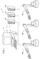
図1に示すように、本実施の形態において使用するオフラインティーチング装置10は、溶接用の第1多関節ロボット50a、第2多関節ロボット50b及び第3多関節ロボット50cの動作のティーチングを行うものであり、作成されたティーチングデータに基づき作業対象物に対して所望の作業を行うロボット装置12と連係されている。
【0018】
また、ロボット装置12は、第1〜第3多関節ロボット50a、50b、50cと、ティーチングデータに基づいて前記第1〜第3多関節ロボット50a、50b、50cのそれぞれの動作制御を行うロボット制御部22a、22b、22cとを備える。
【0019】
図2に示すように、オフラインティーチング装置10を構成する制御部14は、オフラインティーチング装置10の全体の制御を行う制御手段としてのCPU(コンピュータ)26と、記録部であるROM28及びRAM29と、ハードディスク34に対してデータのアクセスを行うハードディスクドライブ(HDD)36と、モニタ16の画面上における描画制御を行う描画制御回路30と、入力装置としてのキーボード18及びマウス20が接続されるインタフェース回路32と、外部記録媒体38a(例えば、磁気的、光学的に記録・読み込み可能なディスク等)を制御する記録媒体ドライブ38とを有する。
【0020】
ハードディスク34には、第1〜第3多関節ロボット50a、50b、50cの動作経路を設定する機能等をもつ相互干渉検証プログラム35、相互干渉の検証結果を記録するデータベース37及び図示しないOS等が格納されている。
【0021】
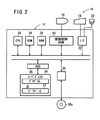
図3に示すように、相互干渉検証プログラム35は、RAM29及びハードディスク34等からデータを読み込む機能を持つデータ読込み部100と、データを書き込む機能を持つデータ書込み部102と、キーボード18及びマウス20等の入力状態を監視するオペレータ指示認識部104と、第1〜第3多関節ロボット50a、50b、50cの姿勢データを3次元CADによって定義されているロボットモデルに設定して描画する画像作成部106を有する。
【0022】
画像作成部106は、オペレータが設定するロボット姿勢設定コマンドと、描画コマンドとによりAPI(Application Programming Interface)を用いて多関節ロボットのモデルや、所定のグラフをモニタ16の画面に描画する機能を持つ。
【0023】
データ読込み部100によって得られたデータは、ロボット動作プログラム生成部108において自動的にロボット動作プログラムに変換・生成されて相互干渉確認部110に伝えられる。ロボット動作プログラム生成部108では、オペレータの操作によって手動的又は半自動的にロボット動作プログラムを生成することも可能である。
【0024】
ロボット動作プログラムは、第1〜第3多関節ロボット50a、50b、50cを制御するプログラムであり、第1〜第3多関節ロボット50a、50b、50cに対して個別のロボット動作プログラムが適用される。このロボット動作プログラムは、ロボット制御部22a、22b、22cにそれぞれロードされた後に実行されるが、制御部14において、シミュレーションに適用して仮実行することも可能である。
【0025】
相互干渉確認部110は、RCSモジュール等によって動作計画を計算する動作計画計算部110aと、第1〜第3多関節ロボット50a、50b、50c同士の相互干渉及び他の障害物との干渉の有無を検証する相互干渉計算部110dを有する。
【0026】
相互干渉計算部110dは、3次元CADをベースにしており、コンピュータプログラム上の仮想空間において、第1〜第3多関節ロボット50a、50b、50cをソリッドモデルとして表し、互いのモデル同士が相互干渉を起こすか否かを検証するものであり、相互干渉の有無を判断するとともに、モニタ16の画面上にその様子を模写的に表示する機能を持つ。
【0027】
さらに、相互干渉確認部110は、RCSモジュールによる任意時刻における第1〜第3多関節ロボット50a、50b、50cの姿勢を計算するロボット姿勢サンプリング部110bと、第1〜第3多関節ロボット50a、50b、50cのうち2台の多関節ロボットの姿勢組合せの記録領域を確保する姿勢組合せ生成部110cと、所定時間毎の第1〜第3多関節ロボット50a、50b、50cの姿勢の変化量を求めるロボット姿勢変化判定部110eとを有する。
【0028】
なお、RCSモジュールとは、一般的な多関節ロボットのモーション設計のためのソフトウェアであり、多関節ロボットの各軸の加減速度を決定する機能等を持ち、ロボット動作データをロボット姿勢サンプリング部110bに擬似的に与えるものである。
【0029】
相互干渉確認部110において検証された結果は相互干渉検証結果記録部112に伝えられ、第1〜第3多関節ロボット50a、50b、50cの姿勢と、相互干渉判別結果と組合せの情報をデータ書込み部102を介してハードディスク34にデータベース37等の形式で記録する。
【0030】
キーボード18及びマウス20の入力情報はオペレータ指示認識部104を介して姿勢組合せ計算部114に伝えられる。姿勢組合せ計算部114では作業開始時点からのオフセット量(動作経過時間)を計算する。
【0031】
求められた第1〜第3多関節ロボット50a、50b、50cの動作経過時間は、ロボット姿勢計算部116へ伝えられる。ロボット姿勢計算部116は、第1〜第3多関節ロボット50a、50b、50cの動作経過時間に相当する第1〜第3多関節ロボット50a、50b、50cの姿勢データをデータベース37等の記録から読み出す。相互干渉検証プログラム35は、データ転送部118を介してデータの入出力を行う。
【0032】
第1〜第3多関節ロボット50a、50b、50cは全て同構造であり、図4に示すように、取付台である第1ベース54に対して、先端側に向かって順に、第2ベース56、第1リンク58、第2リンク60、第3リンク62、第4リンク64及びガン着脱部66が接続されている。先端のガン着脱部66にはガンユニット(エンドエフェクタ)68が接続されている。第1〜第3多関節ロボット50a、50b、50cは、必ずしも同構造でなくてもよい。
【0033】
第2ベース56は鉛直軸である軸J1を中心にして第1ベース54に対して旋回可能に軸支されている。第1リンク58の基端部は水平軸である軸J2により第2ベース56に俯仰可能に軸支されている。また、第2リンク60の基端部は水平軸である軸J3により第1リンク58の先端部に揺動可能に軸支されている。そして、第3リンク62は第2リンク60の先端側に軸J4を共通の回転中心軸として接続されている。さらに、第4リンク64の基端部は軸J4に対して直角方向の軸J5により第3リンク62の先端部に揺動可能に軸支されている。ガン着脱部66は第4リンク64の先端側に軸J6を共通の回転中心軸として接続されている。
【0034】
ガン着脱部66に接続されたガンユニット68はいわゆるC型溶接ガンであり、アーチ状のアーム74の両端部には、ガン軸J7に沿って開閉する一対の電極70、72を有する。この電極70、72は閉状態ではガン軸J7上の作業点(以下、TCP(Tool Center Point)という。)において図示しないワークに接触する。
【0035】
軸J1〜J6の駆動機構並びに電極70、72の進退機構(つまり、ガン軸J7)は、それぞれ図示しないアクチュエータにより駆動され、TCPは軸J1〜J6のそれぞれの回転角θ1〜θ6の値及び第1〜第3多関節ロボット50a、50b、50cの各部寸法により決定される。
【0036】
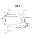
また、ガンユニット68はC型溶接ガンに限らず、例えば、図5に示すX型溶接ガン(共通の支軸に軸支された開閉する一対のガンアームを備える溶接ガン)68aであってもよい。
【0037】
図6に示すように、第1多関節ロボット50aの動作を途中の教示姿勢点Pn(n=1、2、3…)における姿勢として記録するパステーブル180は、「ガンユニットの向き」欄180a、「TCPの位置」欄180b及び「各軸角度」欄180cから構成されており、「各軸角度」欄180cは回転角θ1〜θ6から構成されている。「ガンユニットの向き」欄180a及び「TCPの位置」欄180bは、それぞれ3つのパラメータで表されている。
【0038】
図6に示す例では、8つの教示姿勢点P1〜P8によってパステーブル180が構成されている例を示しているが、動作経路が最終的に初期位置である教示姿勢点P1に戻るような経路であるときには最終の教示姿勢点P8をP1に置き換えるとよい。
【0039】
なお、第2及び第3多関節ロボット50b、50cについても同様のパステーブルが存在する。
【0040】
次に、このように構成されるオフラインティーチング装置10及び相互干渉検証プログラム35を用いて、第1及び第2多関節ロボット50a、50bの相互干渉を検証する方法について図7〜図12を参照しながら説明する。
【0041】
以下の説明では、第1〜第3多関節ロボット50a、50b、50cのうち2台の第1及び第2多関節ロボット50a、50bについて相互干渉を検証する方法を例にして説明する。また、以下の処理は、基本的に相互干渉検証プログラム35によって自動的に行われる。
【0042】
先ず、図7のステップS1において、ロボット動作プログラム生成部108が、パステーブル180等のデータを読み込み、第1及び第2多関節ロボット50a、50bについてそれぞれロボット動作プログラムを生成する。
【0043】
次に、ステップS2において、動作計画計算部110aがパステーブル180とRCSモジュールに基づいて第1及び第2多関節ロボット50a、50bの動作計画を生成する。この動作計画は、パステーブル180で表されている教示姿勢点Pn間を動作速度等の条件によって補間するものである。
【0044】
この動作計画は、第1及び第2多関節ロボット50a、50bの各80[sec]間の動作を表し、それぞれ1[sec]毎にサンプリングした80通りの姿勢によって構成されるものとする。
【0045】
次に、ステップS3において、ロボット姿勢サンプリング部110bが、生成された動作計画から、各サンプリング時刻、すなわち各オフセット量における第1及び第2多関節ロボット50a、50bのロボット姿勢データを計算する。つまり、各サンプリング時刻におけるTCPや各回転角θ1〜θ6を計算して記録する。
【0046】
次に、ステップS4において、ロボット姿勢変化判定部110eがサンプリング結果から第1多関節ロボット50aの所定時間毎の姿勢変化量εを求め、姿勢変化が大きい箇所の抽出を行う。このステップS4の詳細な処理については後述する。
【0047】
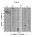
次に、ステップS5において、姿勢組合せ生成部110cが、サンプリングした姿勢での組合せを示す組合せデータ210(図8参照)を記録するための記録領域をRAM29上に確保する。組合せデータ210は、図8から了解されるように、微小時間毎の等間隔ではなく、第1多関節ロボット50aの動作時間が間引かれているので、記録容量を低減することができる。
【0048】
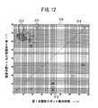
図8に示す例は、組合せデータ210を模式的に示したものであり、第1多関節ロボット50aのサンプリング数を横方向にとり、第2多関節ロボット50bのサンプリング数を縦方向にとることにより平面状に表している。
【0049】
次に、ステップS6において、ロボット姿勢変化判定部110eで記録した比較時間tcに対して、第2多関節ロボット50bとの干渉判別計算を行う。
【0050】
つまり、前記ステップS4で抽出した比較時間tcにおける第1多関節ロボット50aの姿勢に対して、前記ステップS3で計算した動作姿勢を適用する。そして各姿勢の組合せについて、3次元CADの標準的な機能により、第1多関節ロボット50aと第2多関節ロボット50bとが干渉しているか否かを確認する。
【0051】
干渉が確認された組合せについては、組合せデータ210上の相当するメモリに干渉を示すマーク212を記録する。図8に示す例では、マーク212が黒丸「●」で示される。また、組合せデータ210では、第1多関節ロボット50a及び第2多関節ロボット50bが想定通りに動作した場合には、対角状に設定される行程線214に沿って動作する。従って、図8に示す例では、行程線214上にマーク212が存在しないことから、一方が途中停止するトラブルがなければ相互干渉を起こすことなく動作可能であることが確認できる。
【0052】
なお、第1多関節ロボット50aの動作は、パステーブル180(図6参照)の「番号」欄で示されるように、所定の教示番号を示す教示姿勢点P1、P2…によって区切られている。これらの教示番号で区切られたエリアのうち干渉が検出されたエリアについては、そのエリアの手前で停止させる必要があるため、干渉確認の時間間隔を適当に伸ばしてもよい。干渉確認の時間間隔を伸ばすことによって処理時間を短縮することができる。
【0053】
次に、ステップS7において、相互干渉検証結果記録部112が干渉判別結果として組合せデータ210をデータベース37としてハードディスク34に記録する。
【0054】
このようにして、第1及び第2多関節ロボット50a、50bが動作する際の相互干渉の状況を検証することができる。
【0055】
次に、前記ステップS4で実行する処理について図9を参照しながら説明する。このステップS4の処理は主にロボット姿勢変化判定部110eによって自動的に実行される。
【0056】
先ず、ステップS101において、基準時間tbと比較時間tcを初期値に設定する。つまり、基準時間tbを作業時間の開始時間に設定するとともに、比較時間tcを基準時間tbに対して所定の短い時間幅Δtを加算した値に設定する。基準時間tbと比較時間tcは、ステップS105及びステップS107で更新される。時間幅Δtはサンプリング幅に設定するとよく、上記の例では1[sec]とするとよい。
【0057】
次に、ステップS102において、その時点における比較時間tcと作業時間の終了時間とを比較する。比較時間tcが作業時間に達しているときには図9に示す処理を終了してステップS5(図7参照)へ移り、未達であるときには次のステップS103に進む。
【0058】
ステップS103においては、基準時間tbと比較時間tcとの間における第1多関節ロボット50aの姿勢変化量εを求める。
【0059】
具体的には、基準時間tbにおける第1多関節ロボット50aの各軸の回転角θ1〜θ6がθ01、θ02、θ03、θ04、θ05及びθ06で、比較時間tcにおける回転角がθ11、θ12、θ13、θ14、θ15及びθ16であるとき、姿勢変化量εを次の(1)式により求める。
ε=a1・|θ01−θ11|+a2・|θ02−θ12|+a3・|θ03−θ13|+a4・|θ04−θ14|+a5・|θ05−θ15|+a6・|θ06−θ16| …(1)
【0060】
ここで、a1〜a6は、各軸J1〜J6に対する重み付けのための正の係数であり、第1多関節ロボット50aの構造によって予め設定されている。第1多関節ロボット50aの姿勢変化は、例えば、先端側の軸J6の回転角であるθ6よりも、第1ベース54に近い軸J1の回転角であるθ1によって大きく影響を受けることから、θ6に関する係数a6よりもθ1に関する係数a1を大きく設定するとよい。
【0061】
この(1)式によれば、例えば、基準時間tb及び比較時間tcでTCPの位置が一定である場合にも、その他の部分が変位していることを定量的に判断することができる。
【0062】
なお、C型溶接ガンであるガンユニット68の電極72が変位しても、第1多関節ロボット50aの姿勢は変化しないことから、第2多関節ロボット50bに干渉することはないと判断できる。従って、(1)式では、電極72の移動量を示す項は含まれていない。これに対して、X型溶接ガン68a(図5参照)を用いる場合では、電極80、82を保持する指示部が大きく変位するので、電極80、82の移動量を示す項を付加するとよい。
【0063】
また、電極72の移動量は、他のロボットと干渉することがないことが明らかであるから、この電極の移動量は、(1)式に加えなくてもよい。
【0064】
姿勢変化量εは、(1)式に限らず、第1多関節ロボット50aの姿勢の変化を定量的に示すことのできる式により求めればよい。
【0065】
次に、ステップS104において、姿勢変化量εを所定の閾値Cと比較する。姿勢変化量εが閾値Cより小さいときにはステップS105に移り、姿勢変化量εが閾値C以上であるときには次のステップS106に移る。閾値Cは、第1多関節ロボット50aの姿勢変化の大小を区別することのできる適当な値であり、予め設定されている。
【0066】
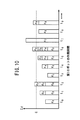
具体的には、図10に示すように、姿勢変化量εの積算値Σεが閾値Cを超えた時間を抽出することができる。図10では、作業時間を時間t0、t1、t2…(時間幅Δt)と表すとともに、n=1、2、3…として、時間tn〜t(n+1)の姿勢変化量εをεnと表している。積算値Σεは、閾値Cを超える毎にリセットされるように処理されて、積算値Σεが閾値Cを超えた時間t2、t6、t7及びt9が抽出されるとともに時間t0、t1、t3、t4、t5及びt8は省かれる。なお、図10はロボット姿勢変化判定部110eが行う処理をイメージ的に表現したものであって、θ1〜θ6の正負符合によって、姿勢変化量εが必ずしもそのまま積算されないこともあるが、(1)式によれば基準時間tbにおける前記第1多関節ロボット50aの姿勢に対して姿勢変化量εが閾値Cより大きくなる比較時間tcを確実に抽出することができる。
【0067】
ステップS105においては、比較時間tcを時間幅Δtだけ増加・更新した後にステップS102に戻る。このように、基準時間tbの値を維持して比較時間tcだけを更新することにより、第1多関節ロボット50a姿勢変化量εが閾値Cを下回るまま連続して動作する場合でも、その変化量を積算的に処理することになり、やがて姿勢変化量εが閾値C以上となって、ステップS106に移るようになる。
【0068】
一方、ステップS106においては、その時点における比較時間tcを記録するとともに、所定のメモリ領域を確保する。
【0069】
次に、ステップS107において、基準時間tbにその時点の比較時間tcを代入するとともに、新たな比較時間tcを基準時間tbより時間幅Δtだけ長く設定する。これにより、基準時間tbと比較時間tcとの時間幅はΔtとなる。この後、ステップS102に戻り処理を続行する。
【0070】
図7及び図9のフローチャートで示される処理が終了した後、記録されたデータベース37等に基づいて、干渉を検証するグラフを作成するとよい。このグラフは、例えば、前記特許文献1で開示されている方法により作成するとよい。さらに、干渉が確認されたエリアについては所定のインターロックを設けることにより、ロボットの相互干渉を防止することができる。
【0071】
また、第1多関節ロボット50aと第3多関節ロボット50cとの相互干渉、及び第2多関節ロボット50bと第3多関節ロボット50cとの相互干渉についても同様に検証することができる。
【0072】
この方法では、単にTCPの移動距離だけでなく、各軸J1〜J6の姿勢変化を考慮していることから、例えば、図11に示すように、TCPの移動距離が少ない場合であってもガンユニット68が反転するような場合には、干渉確認を行うようにすることができる。
【0073】
上記の説明では、第1多関節ロボット50aの姿勢変化量εに基づいて、干渉確認回数を低減する例について説明したが、図12に示すように、第2多関節ロボット50bについても姿勢の変化の少ない箇所を間引くようにしてもよい。
【0074】
また、電極70、72に通電して溶接を行っている最中には、ロボットは動作しないことから、少なくともこの間における検証回数を削減することができる。
【0075】
この発明に係るロボットの相互干渉検証方法は、上述の実施の形態例に限らず、この発明の要旨を逸脱することなく、種々のステップを採り得ることはもちろんである。
【0076】
【発明の効果】
以上説明したように、本発明に係るロボットの相互干渉検証方法によれば、2台のロボットが同時に動作する際に、一方のロボットの姿勢変化量が小さい箇所については相互干渉の有無を検証する時間を伸ばすことにより、短時間で検証を行うことができるという効果が達成される。
【図面の簡単な説明】
【図1】本実施の形態で使用するオフラインティーチング装置及びロボット装置を示す説明図である。
【図2】オフラインティーチング装置の構成を示すブロック図である。
【図3】相互干渉検証プログラムの構成を示すブロック図である。
【図4】多関節ロボットの構成を示す説明図である。
【図5】X型溶接ガンを示す説明図である。
【図6】パステーブルを示す説明図である。
【図7】本実施の形態に係るロボットの相互干渉検証方法の手順を示すフローチャートである。
【図8】第1多関節ロボットについて姿勢の変化の少ない箇所を間引いた組合せデータを示す説明図である。
【図9】ロボット姿勢変化判定部によって、第1多関節ロボットの姿勢変化量の小さい箇所を抽出する手順を示すフローチャートである。
【図10】ロボット姿勢変化判定部によって、第1多関節ロボットの姿勢変化量の小さい箇所が抽出された比較時間を示す模式図である。
【図11】ロボットの姿勢変化量が大きいときで、TCPの移動量が小さい場合のガンユニットの移動状態を示す模式図である。
【図12】第1多関節ロボット及び第2多関節ロボットの双方について姿勢の変化の少ない箇所を間引いた組合せデータを示す説明図である。
【符号の説明】
10…オフラインティーチング装置 12…ロボット装置
14…制御部 16…モニタ
18…キーボード 20…マウス
22a〜22c…ロボット制御部 26…CPU(コンピュータ)
28…ROM 29…RAM
34…ハードディスク 35…相互干渉検証プログラム
37…データベース 50a〜50c…多関節ロボット
68…ガンユニット 68a…X型溶接ガン
70、72、80、82…電極 100…データ読込み部
102…データ書込み部
108…ロボット動作プログラム生成部 110…相互干渉確認部
110a…動作計画計算部
110b…ロボット姿勢サンプリング部 110c…姿勢組合せ生成部
110d…相互干渉計算部 110e…ロボット姿勢変化判定部
112…相互干渉検証結果記録部 114…姿勢組合せ計算部
116…ロボット姿勢計算部 180…パステーブル
210…組合せデータ[0001]
TECHNICAL FIELD OF THE INVENTION
The present invention relates to a method for verifying mutual interference between robots, and more particularly, to a method for verifying mutual interference between robots for quickly verifying the interference between two robots.
[0002]
[Prior art]
Conventionally, when teaching the working posture by directly operating the articulated robot installed on the production line, an operator who is familiar with the operation of the articulated robot must perform work at the production line site, which is not enough. The work becomes inefficient. In addition, since the work needs to be performed while the production line is stopped, the operation rate of the production line is reduced.
[0003]
Accordingly, offline teaching (off-line teaching) has been performed in order to improve the efficiency of the recent teaching work or to improve the operation rate of the production line. That is, a model of an articulated robot and a work and a peripheral structure which is an object to be worked is constructed on a computer, teaching data is created using the model, and then the teaching data is supplied to an articulated robot at a site. In this case, there is no need to stop the production line while creating teaching data.
[0004]
By the way, recently, for the purpose of improving productivity and the like, a plurality of articulated robots are adopted in one process, and work modes for operating these articulated robots simultaneously and intensively are increasing. In particular, when working on a work having a complicated shape, the articulated robots may be densely arranged. In such a work mode, the operation program must be set so as to avoid interference with the workpiece and other obstacles, and also to avoid interference between the articulated robots.
[0005]
As a verification method for this, a method has been proposed in which the posture of one robot is obtained at every predetermined operation time, and all postures in the working time of the other robot correspond to the posture to verify the presence or absence of interference. (For example, see Patent Document 1).
[0006]
[Patent Document 1]
JP-A-2003-103491 (FIG. 6)
[0007]
[Problems to be solved by the invention]
The method disclosed in
[0008]
However, the time width for checking the interference is set to a very short time, or the number of times of checking increases when the working time is long, and it takes a lot of time to verify the mutual interference. Therefore, it is practically difficult to perform the verification many times while changing the conditions. In addition, the time for occupying the computer used for verification is long.
[0009]
The present invention has been made in view of such a problem, and provides a method of verifying mutual interference of robots that enables a short time to verify the presence or absence of mutual interference when two robots operate simultaneously. The purpose is to provide.
[0010]
[Means for Solving the Problems]
The method for verifying mutual interference of robots according to the present invention is the method for verifying mutual interference between the first and second robots when the first robot and the second robot perform work. A first step of obtaining and recording the posture of the first robot at every predetermined time in; a second step of obtaining and recording the posture of the second robot at every predetermined time in the work; Verifying whether or not the posture of the second robot recorded in the second step interferes with the posture of the first robot recorded in the first step. The third step is executed again when the amount of change in posture of the first robot is larger than a predetermined threshold with respect to the posture of the first robot at the time of the previous execution.
[0011]
As described above, when the posture change amount of the first robot becomes larger than the predetermined threshold, the verification of the mutual interference is performed, so that the number of times of the verification can be reduced, and the presence or absence of the mutual interference can be verified in a short time. Can be. When the posture change amount is small, it can be determined that the state relating to the mutual interference between the first robot and the second robot hardly changes, so that the execution interval of the verification can be extended.
[0012]
In this case, when it is confirmed in the third step that the first robot and the second robot interfere with each other, the execution interval of the third step may be extended.
[0013]
Further, the first robot is an articulated robot having a plurality of movable parts, and the posture change amount is obtained by weighting and adding each displacement amount of the movable part. Good.
[0014]
In this case, the robot may be provided with a C-type welding gun having a pair of electrodes, and the amount of change in the posture may be calculated based on the amount of movement of the other movable part excluding the amount of movement of the electrodes. . The forward / backward movement of the electrode in the C-type welding gun can be omitted because it does not affect the posture change of the robot. Thus, when only the electrodes operate, the amount of change in the posture becomes a constant value, and the execution interval of the verification can be further extended.
[0015]
Further, the robot may be provided with an X-type welding gun having a pair of electrodes, and the amount of change in posture may be calculated including the amount of movement of the electrodes. Thereby, when the electrode of the X-type welding gun operates largely, the mutual interference can be verified.
[0016]
BEST MODE FOR CARRYING OUT THE INVENTION
Hereinafter, an embodiment of a mutual interference verification method using a mutual interference display pattern of a robot according to the present invention will be described with reference to FIGS.
[0017]
As shown in FIG. 1, an
[0018]
Further, the
[0019]
As shown in FIG. 2, the
[0020]
The
[0021]
As shown in FIG. 3, the mutual
[0022]
The
[0023]
The data obtained by the data reading unit 100 is automatically converted and generated into a robot operation program in the robot operation
[0024]
The robot operation program is a program for controlling the first to third articulated
[0025]
The mutual
[0026]
The mutual interference calculation unit 110d is based on a three-dimensional CAD, and represents the first to third articulated
[0027]
Further, the mutual
[0028]
The RCS module is software for designing the motion of a general articulated robot, has a function of determining the acceleration / deceleration of each axis of the articulated robot, and sends the robot operation data to the robot posture sampling unit 110b. It is given in a pseudo manner.
[0029]
The result verified by the mutual
[0030]
The input information of the
[0031]
The determined operation elapsed time of the first to third articulated
[0032]
The first to third articulated
[0033]
The
[0034]
The
[0035]
The drive mechanism for the axes J1 to J6 and the advance / retreat mechanism for the
[0036]
The
[0037]
As shown in FIG. 6, the path table 180 that records the operation of the first articulated
[0038]
In the example shown in FIG. 6, an example in which the path table 180 is configured by eight teaching posture points P1 to P8 is shown, but a path in which the motion path eventually returns to the teaching posture point P1, which is the initial position. , The last teaching posture point P8 may be replaced with P1.
[0039]
A similar path table exists for the second and third articulated
[0040]
Next, a method of verifying the mutual interference between the first and second articulated
[0041]
In the following description, a method of verifying mutual interference between two first and second articulated
[0042]
First, in step S1 of FIG. 7, the robot operation
[0043]
Next, in step S2, the motion plan calculation unit 110a generates a motion plan for the first and second articulated
[0044]
This motion plan represents the motion of each of the first and second articulated
[0045]
Next, in step S3, the robot posture sampling unit 110b calculates the robot posture data of the first and second articulated
[0046]
Next, in step S4, the robot posture change determination unit 110e obtains the posture change amount ε of the first articulated
[0047]
Next, in step S5, the posture combination generation unit 110c secures a recording area on the
[0048]
The example shown in FIG. 8 schematically shows the
[0049]
Next, in step S6, an interference determination calculation with the second articulated
[0050]
That is, the motion posture calculated in step S3 is applied to the posture of the first articulated
[0051]
For the combination for which interference has been confirmed, a
[0052]
The operation of the first articulated
[0053]
Next, in step S7, the mutual interference verification
[0054]
In this way, it is possible to verify the state of mutual interference when the first and second articulated
[0055]
Next, the processing executed in step S4 will be described with reference to FIG. The process of step S4 is mainly automatically executed mainly by the robot posture change determination unit 110e.
[0056]
First, in step S101, the reference time tb and the comparison time tc are set to initial values. That is, the reference time tb is set to the start time of the work time, and the comparison time tc is set to a value obtained by adding a predetermined short time width Δt to the reference time tb. The reference time tb and the comparison time tc are updated in steps S105 and S107. The time width Δt may be set to the sampling width, and may be set to 1 [sec] in the above example.
[0057]
Next, in step S102, the comparison time tc at that time is compared with the end time of the work time. When the comparison time tc has reached the work time, the processing shown in FIG. 9 is terminated and the process proceeds to step S5 (see FIG. 7). When the comparison time tc has not reached the work time, the process proceeds to the next step S103.
[0058]
In step S103, the posture change amount ε of the first articulated
[0059]
Specifically, the rotation angles θ1 to θ6 of the respective axes of the first articulated
ε = a1 · | θ01-θ11 | + a2 · | θ02-θ12 | + a3 · | θ03-θ13 | + a4 · | θ04-θ14 | + a5 · | θ05-θ15 | + a6 · | θ06-θ16 | (1)
[0060]
Here, a1 to a6 are positive coefficients for weighting the axes J1 to J6, and are set in advance by the structure of the first articulated
[0061]
According to the equation (1), for example, even when the position of the TCP is constant at the reference time tb and the comparison time tc, it can be quantitatively determined that the other parts are displaced.
[0062]
In addition, even if the electrode 72 of the
[0063]
Further, since it is clear that the moving amount of the electrode 72 does not interfere with another robot, the moving amount of the electrode need not be added to the expression (1).
[0064]
The posture change amount ε is not limited to the expression (1), but may be obtained by an expression that can quantitatively indicate a change in the posture of the first articulated
[0065]
Next, in step S104, the posture change amount ε is compared with a predetermined threshold value C. When the posture change amount ε is smaller than the threshold value C, the process proceeds to step S105. When the posture change amount ε is equal to or larger than the threshold value C, the process proceeds to the next step S106. The threshold value C is an appropriate value capable of discriminating the magnitude of the posture change of the first articulated
[0066]
Specifically, as shown in FIG. 10, it is possible to extract the time during which the integrated value Σε of the posture change amount ε exceeds the threshold value C. In FIG. 10, the work time is represented by time t0, t1, t2... (Time width Δt), and the amount of posture change ε from time tn to t (n + 1) is represented by εn, where n = 1, 2, 3,. I have. The integrated value Σε is processed so as to be reset every time the integrated value 閾 値 ε exceeds the threshold value C, and the times t2, t6, t7 and t9 when the integrated value Σε exceeds the threshold value C are extracted, and the times t0, t1, t3 and t4 are obtained. , T5 and t8 are omitted. FIG. 10 illustrates the processing performed by the robot posture change determination unit 110e as an image. Depending on the sign of θ1 to θ6, the posture change amount ε may not always be integrated as it is, but (1) According to the equation, it is possible to reliably extract the comparison time tc at which the posture change amount ε is larger than the threshold value C with respect to the posture of the first articulated
[0067]
In step S105, the comparison time tc is increased / updated by the time width Δt, and then the process returns to step S102. As described above, by maintaining the value of the reference time tb and updating only the comparison time tc, even if the first articulated
[0068]
On the other hand, in step S106, the comparison time tc at that time is recorded, and a predetermined memory area is secured.
[0069]
Next, in step S107, the comparison time tc at that time is substituted for the reference time tb, and the new comparison time tc is set longer than the reference time tb by the time width Δt. Thus, the time width between the reference time tb and the comparison time tc becomes Δt. Thereafter, the process returns to step S102 to continue the process.
[0070]
After the processing shown in the flowcharts of FIGS. 7 and 9 is completed, a graph for verifying interference may be created based on the recorded
[0071]
Further, the mutual interference between the first articulated
[0072]
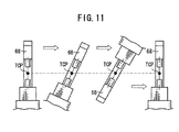
In this method, since not only the movement distance of the TCP but also the attitude change of each axis J1 to J6 is taken into consideration, for example, as shown in FIG. In the case where the
[0073]
In the above description, an example in which the number of interference confirmations is reduced based on the posture change amount ε of the first articulated
[0074]
In addition, the robot does not operate while welding is being performed by energizing the
[0075]
The method for verifying mutual interference of robots according to the present invention is not limited to the above-described embodiment, and it is needless to say that various steps can be taken without departing from the gist of the present invention.
[0076]
【The invention's effect】
As described above, according to the method for verifying mutual interference of robots according to the present invention, when two robots operate simultaneously, the presence or absence of mutual interference is verified for a portion where the amount of change in posture of one of the robots is small. By extending the time, the effect that the verification can be performed in a short time is achieved.
[Brief description of the drawings]
FIG. 1 is an explanatory diagram showing an offline teaching device and a robot device used in the present embodiment.
FIG. 2 is a block diagram illustrating a configuration of an offline teaching device.
FIG. 3 is a block diagram illustrating a configuration of a mutual interference verification program.
FIG. 4 is an explanatory diagram illustrating a configuration of an articulated robot.
FIG. 5 is an explanatory view showing an X-type welding gun.
FIG. 6 is an explanatory diagram showing a path table.
FIG. 7 is a flowchart showing a procedure of a robot mutual interference verification method according to the present embodiment.
FIG. 8 is an explanatory diagram showing combination data obtained by thinning out portions of the first multi-joint robot where there is little change in posture.
FIG. 9 is a flowchart illustrating a procedure for extracting a portion of the first articulated robot with a small amount of change in posture by the robot posture change determination unit.
FIG. 10 is a schematic diagram illustrating a comparison time when a portion of the first articulated robot having a small amount of change in posture is extracted by the robot posture change determination unit;
FIG. 11 is a schematic diagram illustrating a moving state of the gun unit when the amount of change in the posture of the robot is large and the amount of movement of the TCP is small.
FIG. 12 is an explanatory diagram showing combination data obtained by thinning out portions having small changes in posture for both the first articulated robot and the second articulated robot.
[Explanation of symbols]
10 Off-
14: control unit 16: monitor
18 ...
22a to 22c: robot control unit 26: CPU (computer)
28 ...
34: Hard disk 35: Mutual interference verification program
37 ...
68 ...
70, 72, 80, 82 ... electrode 100 ... data reading unit
102: Data writing unit
108: Robot operation program generation unit 110: Mutual interference confirmation unit
110a: operation plan calculation unit
110b: Robot posture sampling unit 110c: Posture combination generation unit
110d: Mutual interference calculation unit 110e: Robot posture change judgment unit
112: Mutual interference verification result recording unit 114: Attitude combination calculation unit
116: robot posture calculation unit 180: path table
210 ... combination data
Claims (5)
前記作業における所定時間毎の前記第1ロボットの姿勢を求めて記録する第1ステップと、
前記作業における所定時間毎の前記第2ロボットの姿勢を求めて記録する第2ステップと、
前記作業の時間順に、前記第1ステップで記録した前記第1ロボットの姿勢に対して前記第2ステップで記録した前記第2ロボットの姿勢が干渉するか否かを検証する第3ステップと、
を実行する方法であって、
前記第3ステップは、前回実行時における前記第1ロボットの姿勢に対して姿勢変化量が所定閾値より大きいときに再度実行することを特徴とするロボットの相互干渉検証方法。In the method of verifying mutual interference between the first and second robots when the first robot and the second robot perform a task,
A first step of obtaining and recording the posture of the first robot at every predetermined time in the work;
A second step of obtaining and recording the posture of the second robot for each predetermined time in the work;
A third step of verifying whether or not the posture of the second robot recorded in the second step interferes with the posture of the first robot recorded in the first step in order of the time of the work;
A method of performing
The third step is a robot interference verification method, wherein the third step is performed again when the amount of change in posture of the first robot is larger than a predetermined threshold with respect to the posture of the first robot at the time of the previous execution.
前記第3ステップで、前記第1ロボットと前記第2ロボットが干渉することが確認されたときに、前記第3ステップの実行間隔を延ばすことを特徴とするロボットの相互干渉検証方法。The method for verifying mutual interference of robots according to claim 1,
A method for verifying mutual interference of robots, wherein, when it is confirmed in the third step that the first robot and the second robot interfere with each other, an execution interval of the third step is extended.
前記第1ロボットは複数の可動部を有する多関節型のロボットであり、前記可動部の各変位量に対して重み付けを付けて加算することにより、前記姿勢変化量を求めることを特徴とするロボットの相互干渉検証方法。The method for verifying mutual interference of robots according to claim 1 or 2,
The first robot is an articulated robot having a plurality of movable parts, and obtains the posture change amount by weighting and adding each displacement amount of the movable part. Mutual interference verification method.
前記ロボットには一対の電極を備えるC型溶接ガンが設けられ、前記姿勢変化量は、前記電極の移動量を除く他の可動部の移動量に基づいて算出することを特徴とするロボットの相互干渉検証方法。The method for verifying mutual interference of robots according to claim 3,
The robot is provided with a C-type welding gun having a pair of electrodes, and the amount of change in the posture is calculated based on the amount of movement of other movable parts excluding the amount of movement of the electrodes. Interference verification method.
前記ロボットには一対の電極を備えるX型溶接ガンが設けられ、前記姿勢変化量は、前記電極の移動量を含めて算出することを特徴とするロボットの相互干渉検証方法。The method for verifying mutual interference of robots according to claim 3,
A method of verifying mutual interference of a robot, wherein the robot is provided with an X-type welding gun having a pair of electrodes, and the amount of change in posture is calculated including a movement amount of the electrodes.
Priority Applications (1)
| Application Number | Priority Date | Filing Date | Title |
|---|---|---|---|
| JP2003156532A JP3957296B2 (en) | 2003-06-02 | 2003-06-02 | Robot mutual interference verification method |
Applications Claiming Priority (1)
| Application Number | Priority Date | Filing Date | Title |
|---|---|---|---|
| JP2003156532A JP3957296B2 (en) | 2003-06-02 | 2003-06-02 | Robot mutual interference verification method |
Publications (2)
| Publication Number | Publication Date |
|---|---|
| JP2004358564A true JP2004358564A (en) | 2004-12-24 |
| JP3957296B2 JP3957296B2 (en) | 2007-08-15 |
Family
ID=34050588
Family Applications (1)
| Application Number | Title | Priority Date | Filing Date |
|---|---|---|---|
| JP2003156532A Expired - Fee Related JP3957296B2 (en) | 2003-06-02 | 2003-06-02 | Robot mutual interference verification method |
Country Status (1)
| Country | Link |
|---|---|
| JP (1) | JP3957296B2 (en) |
Cited By (2)
| Publication number | Priority date | Publication date | Assignee | Title |
|---|---|---|---|---|
| JP2012106316A (en) * | 2010-11-18 | 2012-06-07 | Honda Motor Co Ltd | Method and device for detecting interference |
| JP2016537143A (en) * | 2013-08-16 | 2016-12-01 | インテュイティブ サージカル オペレーションズ, インコーポレイテッド | System and method for cooperative operation between dissimilar devices |
-
2003
- 2003-06-02 JP JP2003156532A patent/JP3957296B2/en not_active Expired - Fee Related
Cited By (7)
| Publication number | Priority date | Publication date | Assignee | Title |
|---|---|---|---|---|
| JP2012106316A (en) * | 2010-11-18 | 2012-06-07 | Honda Motor Co Ltd | Method and device for detecting interference |
| JP2016537143A (en) * | 2013-08-16 | 2016-12-01 | インテュイティブ サージカル オペレーションズ, インコーポレイテッド | System and method for cooperative operation between dissimilar devices |
| US10283220B2 (en) | 2013-08-16 | 2019-05-07 | Intuitive Surgical Operations, Inc. | System and method for coordinated motion among heterogeneous devices |
| JP2019072572A (en) * | 2013-08-16 | 2019-05-16 | インテュイティブ サージカル オペレーションズ, インコーポレイテッド | System and method for coordinated motion among heterogeneous devices |
| US11120907B2 (en) | 2013-08-16 | 2021-09-14 | Intuitive Surgical Operations, Inc. | System and method for coordinated motion among heterogeneous devices using a movement token |
| US11710561B2 (en) | 2013-08-16 | 2023-07-25 | Intuitive Surgical Operations, Inc. | System and method for coordinated motion among heterogeneous devices using a movement token |
| US12437868B2 (en) | 2013-08-16 | 2025-10-07 | Intuitive Surgical Operations, Inc. | System and method for coordinated motion among heterogeneous devices |
Also Published As
| Publication number | Publication date |
|---|---|
| JP3957296B2 (en) | 2007-08-15 |
Similar Documents
| Publication | Publication Date | Title |
|---|---|---|
| CN108453702B (en) | Robot simulator, robot system, and simulation method | |
| JP3715537B2 (en) | Interference avoidance method and program for articulated robot | |
| CN111791228B (en) | Programming aid, robot system and programming aid method | |
| JP2015066668A (en) | Method for adjusting teaching point of robot, method for calculating installation position of robot, robot system, program, and recording medium | |
| CN108000523A (en) | Simulator, analogy method and the recording medium of the action of dummy robot's system | |
| JP2012091304A (en) | Teaching data making method and teaching data making device | |
| JP7474681B2 (en) | PROGRAM GENERATION SYSTEM, ROBOT SYSTEM, PROGRAM GENERATION METHOD, AND GENERATION PROGRAM | |
| JP2003103491A (en) | Robot mutual interference verification method and mutual interference display pattern | |
| JP7190152B2 (en) | Teaching data creation method for articulated robots | |
| JP7199073B2 (en) | Teaching data creation system for vertical articulated robots | |
| JP2003103481A (en) | Method and apparatus for optimizing posture of articulated robot | |
| JP5474739B2 (en) | Interference detection method and interference detection apparatus | |
| JP5078770B2 (en) | Teaching data verification method for articulated robots | |
| JP7493926B2 (en) | Control method, control device, robot system, article manufacturing method, operation program creating method, operation program creating device, display device, display device control method, program, and recording medium | |
| JP3957296B2 (en) | Robot mutual interference verification method | |
| JP6576125B2 (en) | Simulation method and simulation apparatus | |
| JP7704851B2 (en) | Robot Simulation Device | |
| JP2003103484A (en) | Robot interlock setting method | |
| JP2007000954A (en) | Robot teaching apparatus and method | |
| JP3577296B2 (en) | Method and device for setting motion path of articulated robot | |
| JP2002239957A (en) | Posture determination method and program for articulated robot | |
| JP2006281330A (en) | Robot simulation device | |
| JP3647404B2 (en) | Motion path setting method and setting device for articulated robot | |
| JP7541955B2 (en) | Robot travelling cart position determination device, method and program | |
| JP4000307B2 (en) | Teaching data creation method for articulated robots |
Legal Events
| Date | Code | Title | Description |
|---|---|---|---|
| A977 | Report on retrieval |
Free format text: JAPANESE INTERMEDIATE CODE: A971007 Effective date: 20060202 |
|
| A131 | Notification of reasons for refusal |
Free format text: JAPANESE INTERMEDIATE CODE: A131 Effective date: 20060207 |
|
| A521 | Request for written amendment filed |
Free format text: JAPANESE INTERMEDIATE CODE: A523 Effective date: 20060410 |
|
| A131 | Notification of reasons for refusal |
Free format text: JAPANESE INTERMEDIATE CODE: A131 Effective date: 20060516 |
|
| A521 | Request for written amendment filed |
Free format text: JAPANESE INTERMEDIATE CODE: A523 Effective date: 20060710 |
|
| A02 | Decision of refusal |
Free format text: JAPANESE INTERMEDIATE CODE: A02 Effective date: 20061226 |
|
| A521 | Request for written amendment filed |
Free format text: JAPANESE INTERMEDIATE CODE: A523 Effective date: 20070226 |
|
| A911 | Transfer to examiner for re-examination before appeal (zenchi) |
Free format text: JAPANESE INTERMEDIATE CODE: A911 Effective date: 20070309 |
|
| TRDD | Decision of grant or rejection written | ||
| A01 | Written decision to grant a patent or to grant a registration (utility model) |
Free format text: JAPANESE INTERMEDIATE CODE: A01 Effective date: 20070501 |
|
| A61 | First payment of annual fees (during grant procedure) |
Free format text: JAPANESE INTERMEDIATE CODE: A61 Effective date: 20070507 |
|
| R150 | Certificate of patent or registration of utility model |
Ref document number: 3957296 Country of ref document: JP Free format text: JAPANESE INTERMEDIATE CODE: R150 Free format text: JAPANESE INTERMEDIATE CODE: R150 |
|
| FPAY | Renewal fee payment (event date is renewal date of database) |
Free format text: PAYMENT UNTIL: 20110518 Year of fee payment: 4 |
|
| FPAY | Renewal fee payment (event date is renewal date of database) |
Free format text: PAYMENT UNTIL: 20110518 Year of fee payment: 4 |
|
| FPAY | Renewal fee payment (event date is renewal date of database) |
Free format text: PAYMENT UNTIL: 20130518 Year of fee payment: 6 |
|
| FPAY | Renewal fee payment (event date is renewal date of database) |
Free format text: PAYMENT UNTIL: 20130518 Year of fee payment: 6 |
|
| FPAY | Renewal fee payment (event date is renewal date of database) |
Free format text: PAYMENT UNTIL: 20140518 Year of fee payment: 7 |
|
| LAPS | Cancellation because of no payment of annual fees |