JP2004354430A - Discrimination medium, articles to be discriminated, judging device, judging method of discrimination medium and manufacturing method of laminated body - Google Patents
Discrimination medium, articles to be discriminated, judging device, judging method of discrimination medium and manufacturing method of laminated body Download PDFInfo
- Publication number
- JP2004354430A JP2004354430A JP2003148659A JP2003148659A JP2004354430A JP 2004354430 A JP2004354430 A JP 2004354430A JP 2003148659 A JP2003148659 A JP 2003148659A JP 2003148659 A JP2003148659 A JP 2003148659A JP 2004354430 A JP2004354430 A JP 2004354430A
- Authority
- JP
- Japan
- Prior art keywords
- light
- thin film
- refractive index
- identification medium
- stretching
- Prior art date
- Legal status (The legal status is an assumption and is not a legal conclusion. Google has not performed a legal analysis and makes no representation as to the accuracy of the status listed.)
- Pending
Links
Images


Abstract
Description
【0001】
【発明の属する技術分野】
本発明は、光の反射を利用して各種の商品、重要書類、各種ICカード、クレジットカード、金券、パスポート、紙幣、証券あるいは切符の真贋を判定する技術に関する。また、そのような真贋判定に利用する積層体の製造に適用して有用な技術に関する。
【0002】
【従来の技術】
上述のような物品の偽造に対しては、偽造品であるか否かを判別できるようにすることが重要となる。
【0003】
これらの物品の真贋を容易に判別できるようにする方法として、偽造が容易でなく特殊な見え方をするシールや印刷を対象物に付着させ、そのシールや印刷を視認することで、正規の製造品であるか否かを判別する方法がある。このような方法として、対象物の表面にホログラムを貼付する方法、あるいは特殊なインクを塗布する方法が知られている(例えば、特許文献1参照)。
【0004】
ホログラムを利用する方法は、立体的に見える像の色が見る角度によって異なる現象を利用して、ホログラムシールの真贋を判別する方法である。特殊なインクを用いる方法は、目視では通常のインクと同じように見える蛍光インクや磁気インクを対象物に塗布し、紫外線の照射や磁気センサにより、それを検出することで、対象物の真贋を判定する方法である。
【0005】
また、コレステリック液晶を用いた識別媒体の反射特性が視野角に依存し、視野角によって微妙に反射光の状態が変化することを利用して、真贋を識別する方法が知られている(例えば、引用文献2参照)。
【0006】
【特許文献1】
特開2001−315243号公報(第2頁、請求項14)
【特許文献2】
特許第3244278号明細書(第7頁、図1、図2)
【0007】
【発明が解決しようとする課題】
ホログラムを利用する方法は、ホログラムの製造が高コストであり、特に、偽造を困難にするために複雑なホログラムを製造しようとすると、さらに高コストになる問題がある。蛍光インクや磁気インクを用いる方法は、同様なインクや類似品を使用されて偽造が行われ、真贋識別効果が得られなくなる問題がある。コレステリック液晶を用いる方法は、コレステリック液晶が高価であり経済的でなく、また激しい温度変化や太陽光に曝された場合の光学特性の劣化あるいは変化があり、長期間安定した性能を発揮させる点で不安がある。
【0008】
本発明は、低コストで得られ、偽造され難く、温度変化や太陽光に曝される等の環境におかれても機能が低下しない真贋判定の技術の提供を目的とする。また、そのような技術に利用できる材料の製造技術を提供することを目的とする。
【0009】
【課題を解決するための手段】
本発明の識別媒体は、屈折率異方性を有する光透過性の第1の薄膜と、この第1の薄膜と積層された光透過性の第2の薄膜とを備え、第1および第2の薄膜に直交する第1の面に含まれる第1の方向において、第1の薄膜の屈折率n11と第2の薄膜の屈折率n21とが異なることを特徴としている。
【0010】
本発明は、積層した材料間に屈折率の違いが存在する場合、その違いに依存して材料間の界面での反射の状態が異なる現象を利用するものである。つまり、屈折率の異なる材料間の界面における光の反射率Rが下記数1のフレネル反射に従う原理を利用し、方向によって屈性率の差が異なる場合に、それに応じて反射光の強度が異なる現象を利用したものである。
【0011】
【数1】

数1において、n1とn2は各材料の屈折率である。
【0013】
また、薄膜が多層に積層されている場合には、最初の境界面で反射されなかった成分が次の境界面で反射され、さらにこの現象が境界面の数だけ繰り返される。よって、一つの境界面での反射率が上記数1で表されるとした場合に、N層の反射境界面があるとすると、トータルの反射率Rtotalは下記数2で示される。
【0014】
【数2】
本発明によれば、第1および第2の薄膜に直交する面に含まれる第1の方向における第1の薄膜の屈折率と第2の薄膜の屈折率とが異なっているので、第1の方向に偏光した光を識別媒体に入射させると、両薄膜の界面において反射が発生する。この反射を観察することで、識別媒体の識別を行うことができる。
【0016】
ここで、所定の方向における屈折率とは、その方向に偏光した直線偏光の光に対して当該薄膜が示す屈折率をいう。屈折率異方性とは、方向によって屈折率に異方性があることをいう。反射状態とは、反射のあるなしの状態、あるいは反射光の強度の状態をいう。また所定の方向に偏光した光というのは、所定の方向に電場ベクトルの振幅方向を有する直線偏光の光をいう。このような所定の方向に偏光した光は、例えば偏光板(偏光子ともいわれる)に自然光(あらゆる偏光方向の光を含んだ偏光の方向分布が一様な光)を通すことで得られる。
【0017】
本発明の識別媒体は、屈折率異方性を有する高分子薄膜を積層することで得ることができ、また後述するように製造方法を工夫することで、特殊な材料を用いなくても得ることができ、低コスト化を実現できる。また、本発明の識別媒体は、高分子材料薄膜の積層物であるので、完成品から各種設定パラメータを推測するのは簡単ではなく、その偽造の困難性を高くできる。また、通常の環境下で物性の変化しにくい材料で構成できるので、温度変化や太陽光に当てる等の厳しい環境におかれても性能の変化や低下が少ない識別媒体が得られる。
【0018】
本発明において、第1の面と異なる第2の面に含まれる第2の方向において、第1の薄膜の屈折率n12と第2の薄膜の屈折率n22とが異なり、|n11−n21|≠|n12−n22|であることが好ましい。このような態様によれば、薄膜間における屈折率の違いに起因する光の反射が、第1の方向に直線偏光した光の場合と、第2の方向に直線偏光した光の場合とで異なるものとなり、それを利用して識別を行える。識別能力を高めるためには、Δn1=|n11−n21|、Δn2=|n12−n22|として、|Δn1−Δn2|の値をできるだけ大きくし、偏光方向の違う光に対する反射率の違いを大きくすることが好ましい。また、第1の面と第2の面とが直交していることが好ましい。
【0019】
本発明において、第1の面に直交する第2の面に含まれる第2の方向における第1の薄膜の屈折率と第2の薄膜の屈折率とが一致していることが好ましい。このような態様によれば、第2の方向に偏光した光は第1の薄膜と第2の薄膜との界面で反射されず、当該界面で反射される第1の方向に偏光した光との反射状態の違いを識別し易くでき、識別媒体の識別を容易に行うことができる。
【0020】
本発明では、屈折率が一致するとは、一方に対して他方が好ましくは±5%以内の範囲、より好ましくは±2%以内の範囲、さらにより好ましくは±1%以内の範囲で一致することをいう。
【0021】
さらに本発明において、第2の薄膜が屈折率異方性を有することが好ましい。
【0022】
さらに本発明において、第1の方向に偏光した入射光に対する反射状態と前記第1の方向以外の方向に偏光した入射光に対する反射状態とを比較することで識別判定が行われることが好ましい。
【0023】
ここで、第1の偏光の方向と入射光の偏光の方向とは、完全に一致していることが理想であるが、その範囲は角度で考えて±10度以内、好ましくは±5度以内、より好ましくは±1度以内であればよい。
【0024】
本発明において、第1の方向に偏光した反射光と前記第1の方向以外の方向に偏光した反射光とを比較することで識別判定が行われると好適である。
【0025】
本発明において、第3の薄膜をさらに備え、前記第3の薄膜に印刷、ホログラム加工または型押し加工が施されていると好適である。また本発明において、第1の薄膜または/および第2の薄膜にホログラム加工または型押し加工が施されていると好適である。
【0026】
本発明は、本発明の識別媒体を備えた識別対象物品として把握することもできる。識別対象物品としては、各種の商品、重要書類、各種ICカード、クレジットカード、金券、パスポート、紙幣、証券、シールあるいは切符等が挙げられる。これらの識別対象物品には、ロゴ、ロットナンバー、バーコード等の印刷がされ、あるいは凹凸やエンボス加工による図柄、模様、ホログラム等が付与されていてもよい。この場合、これら印刷や加工による図柄等を本発明の識別媒体を介して観察することになる。
【0027】
本発明の判定装置は、屈折率異方性を有する光透過性の第1の薄膜と、前記第1の薄膜と積層された光透過性の第2の薄膜とを備え、第1および第2の薄膜に直交する第1の面に含まれる第1の方向において、第1の薄膜の屈折率と第2の薄膜の屈折率とが異なる識別媒体の真贋判定を行う装置であって、識別媒体に光を照射する光照射手段と、識別媒体から反射した反射光を検出する光検出手段と、前記光照射手段または/および前記光検出手段の前に配置された偏光フィルタと、を備えることを特徴とする。本発明の判定装置によれば、本発明の識別媒体の真贋を判定する判定装置が提供される。
【0028】
本発明の判定装置において、偏光フィルタは、第1の方向に偏光した第1の光を透過する機能と、第1の方向と異なる方向に偏光した第2の光を透過する機能と、を備えることが好ましい。
【0029】
本発明の判定装置において、第1の方向に偏光した入射光に対する反射状態と前記第1の方向以外の方向に偏光した入射光に対する反射状態とを比較することで識別判定を行う判定手段をさらに備えることが好ましい。
【0030】
本発明の判定装置において、第1の方向に偏光した反射光と前記第1の方向以外の方向に偏光した反射光とを比較することで識別判定を行う判定手段をさらに備えることが好ましい。
【0031】
本発明の判定方法は、屈折率異方性を有する光透過性の第1の薄膜と、前記第1の薄膜と積層された光透過性の第2の薄膜とを備え、前記第1および第2の薄膜に直交する第1の面に含まれる第1の方向において、前記第1の薄膜の屈折率と前記第2の薄膜の屈折率とが異なる識別媒体の真贋判定を行う方法であって、前記識別媒体に光を照射する光照射ステップと、前記識別媒体から反射した反射光を検出する光検出ステップとを備え、前記光照射ステップにおいて偏光フィルタを介して光を照射し前記光検出ステップにおいてその反射光を検出すること、または前記光照射ステップにおいて自然光をそのまま照射し前記光検出ステップにおいて偏光フィルタを介してその反射光を検出すること、または前記光照射ステップにおいて偏光フィルタを介して光を照射し前記光検出ステップにおいて偏光フィルタを介してその反射光を検出することを特徴とする。
【0032】
本発明の積層体の製造方法は、延伸方向における屈折率の変化が正である第1の材料と延伸方向における屈折率の変化が負である第2の材料とを積層し積層体を得る工程と、所定の方向における屈折率が前記第1の材料と前記第2の材料とにおいて一致するまで、前記積層体を前記所定の方向に延伸する工程とを備えることを特徴とする。
【0033】
本発明の積層方法によれば、本発明の識別媒体を製造することができる。以下、本発明の積層方法の原理について説明する。一般に高分子材料でなる薄膜フィルムを延伸により製造する際、延伸方向の屈折率は、その延伸率に応じて変化する。ここで延伸率Pは、延伸方向における延伸前の寸法をL、延伸後の寸法をL´とすると、P=(L´/L)で求められる。なお、延伸率は延伸比あるいは延伸倍率とも呼ばれる。また、屈折率の変化分(以下Δnとする)は、延伸することで正の値をとる材料(すなわち、延伸することで屈折率が増加する材料)と、逆に延伸することでΔnが負になる材料(すなわち、延伸することで屈折率が減少する材料)とがある。たとえば、PVC(ポリ塩化ビニル)は延伸することで屈折率が増加(Δnが正)し、PMMA(アクリル)は延伸することで屈折率が減少(Δnが負)する。
【0034】
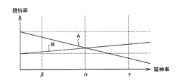
図8は、延伸に従う2つの高分子材料の延伸方向における屈折率の変化の例を示すグラフである。図8には、Δnが負である高分子材料Aの屈折率の変化と、Δnが正である高分子材料Bの屈折率の変化が示されている。なお、図8の縦軸は屈折率の相対的な関係を示す任意値であり、横軸は延伸率の相対的な関係を示す任意値である。
【0035】
たとえば、図8に例示する高分子材料Aと高分子材料Bとを積層し、その積層物を一方向(例えばX軸とする)に延伸する。延伸を進めてゆくと、材料AのX軸方向の屈折率は延伸に従って減少し、材料BのX軸方向の屈折率は延伸に従って増加する。そして、延伸率αで示される点で両材料の屈折率は同じになる。他方でX軸方向に直行するY軸方向に延伸率βまで延伸すると、Y軸方向における屈折率は両薄膜間で異なる値となる。このように延伸率を制御することで、X軸方向では屈折率が一致し、Y軸方向では屈折率が一致しない材料Aと材料Bとでなる積層体を得ることができる。この方法は、材料の延伸に従う光学的な性質の変化を利用したもので、特に特殊な材料や方法を用いなくてもよく、低コストであるという優位性がある。
【0036】
本発明の他の積層体の製造方法は、延伸により該延伸の方向における屈折率が変化しない第1の材料と、延伸により該延伸の方向における屈折率が変化する第2の材料と、を積層し積層体を得る工程と、所定の方向における屈折率が前記第1の材料と前記第2の材料とにおいて一致するまで、前記積層体を前記所定の方向に延伸する工程とを備えることを特徴とする。
【0037】
本発明の他の積層方法によれば、本発明の識別媒体を製造することができる。本発明の他の積層方法の原理について説明する。上述したように、高分子材料をある方向に延伸すると、その方向における屈折率が変化するのであるが、材料に固有なある温度で延伸を行った場合、延伸による屈折率の変化が観察されない、あるいはその変化が小さい現象が観察される。この現象は、ある温度では延伸による配向や結晶化が促進されず、延伸方向における屈折率の変化が現れないことに起因する。この現象を超延伸(super drawing, super elongation)という。超延伸が発生する温度は、一般に材料によって異なり、たとえばPET(ポリエチレン・テレフタレート)の場合で110℃〜120℃である。
【0038】
たとえば、高分子材料Aと高分子材料Bとの積層構造を延伸する場合、材料Aが超延伸を示さず材料Bが超延伸を示す温度で延伸を行うことで、材料Bの延伸方向における屈折率を変化させずに、材料Aの延伸方向における屈折率を変化させることができる。
【0039】
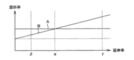
図9は、一方の材料が超延伸を示し、他方の材料が超延伸を示さない温度で延伸を行った場合の屈折率の変化を示すグラフである。図10は、一方の材料が超延伸を示し他方の材料が超延伸を示さない温度で延伸を行った場合の屈折率の変化を示す他の場合のグラフである。なお、図9および図10の縦軸および横軸の意味は図8の場合と同じである。
【0040】
図9の場合、延伸を行っても材料Aの延伸方向における屈折率は変化しないが、材料Bの延伸方向における屈折率は延伸に従って上昇する。よって、延伸がある程度進みαになった時点で、材料Aと材料Bの当該延伸方向における屈折率は一致する。
【0041】
また、材料Bが超延伸を示す温度で材料Aを延伸した場合、図10に示す関係が得られる。この場合、延伸がある程度進んだ延伸率がαの時点で材料Aと材料Bの当該延伸方向における延伸率が一致する。
【0042】
この現象を利用すると、2種類の薄膜を積層し、それをある温度で延伸することで、ある方向では2つの薄膜の屈折率が一致し、その方向に直交する方向では屈折率が異なるような薄膜積層材料を得ることができる。この方法も低コストで実現できる優位性がある。
【0043】
上述の超延伸を用いる方法以外に、同様な効果が得られる方法として、ブレンド法と共重合法を用いた方法がある。ブレンド法とは、延伸に従う屈折率の変化が正である材料と、延伸に従う屈折率が負である材料とを混合した材料で薄膜フィルムを得る技術であり、混合比を調整することで、結果として延伸方向の屈折率の変化が現れない(あるいは変化がほとんど生じない)薄膜フィルムを得る技術である。共重合法とは、高分子鎖を構成するモノマーの配向をランダムにすることで、分極異方性を打ち消し、延伸を行ってもマクロな屈折率異方性が現れないようにする技術である。
【0044】
【発明の実施の形態】
以下に本発明の実施の形態を詳細に説明する。まず、平面方向における屈折率異方性を有する2枚の薄膜フィルムを積層した構造を有し、その平面内の所定の方向(仮にX軸方向とする)における屈折率が一致し、その所定の方向に直交する方向(仮にY軸方向とする)における屈折率が一致しない識別媒体の例を説明する。
【0045】
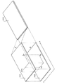
図1は、本実施形態の識別媒体の基本構造を示す模式図である。図1には、それぞれ異なる屈折率異方性を有する薄膜フィルム101と102とを積層した2層構造の識別媒体103が示されている。
【0046】
薄膜フィルム101および102は、光透過性を有する高分子材料からなる薄膜フィルムである。薄膜フィルム101は、図中のX軸方向における屈性率がnAX、Y軸方向における屈性率がnAYであり、薄膜フィルム102は、図中のX軸方向における屈性率がnBX、Y軸方向における屈性率がnBYである。各屈折率の関係は、nAX=nBX、nAY≠nBY(nAY>nBY)である。
【0047】
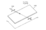
以下、図1に例示する識別媒体の機能について説明する。図2は、図1の識別媒体103にX軸方向に振動する直線偏光の入射光104が入射する状態を示す模式図である。図2に示すようにX軸方向に振動する直線偏光の入射光104が識別媒体103に入射すると、入射光104は、識別媒体103を透過する。
【0048】
これは、薄膜フィルム101のX軸方向における屈折率nAXと、薄膜フィルム102のX軸方向における屈折率nBXが一致しているため、入射光104にとっては、両薄膜フィルムの界面における屈折率の違いが存在せず(あるいは存在しないとみなせる程度に小さく)、そのため両薄膜フィルムの界面における反射がない(あるいは無視できる程度に小さい)からである。
【0049】
図3は、識別媒体103にY軸方向に振動する直線偏光の入射光105が入射する状態を示す模式図である。図3に示すようにY軸方向に振動する直線偏光の入射光105が識別媒体103に入射すると、入射光105は、薄膜フィルム101と薄膜フィルム102との界面において反射される。
【0050】
これは、入射光105にとっての薄膜フィルム101中の屈折率がnAY、薄膜フィルム102中の屈折率がnBYであるところ、nAY>nBYと設定されているので、薄膜フィルム101と薄膜フィルム102との界面において、入射光105の一部が反射されるからである。つまり、入射光105にとっては、薄膜フィルム101と薄膜フィルム102とが示す屈折率が異なるので、前述の数1で表されるフレネル反射の反射率に従った入射光の一部が反射する現象が両薄膜の界面において発生する。
【0051】
こうして、識別媒体103に入射させる光を直線偏光とし、その偏光方向を選ぶことで、入射光の識別媒体103における反射、非反射を観察することができ、この現象を利用して識別媒体103の真贋を判別することができる。
【0052】
たとえば、入射光104と105を個別に照射し、入射光104が透過し、かつ入射光105が反射する状態を観察することで、識別媒体103が所定の構成を有しているかを識別できる。つまり肉眼で見た様子は似ていても、薄膜フィルムの屈折率異方性の組み合わせが、図1に例示するような組み合わせでない場合、入射光104と入射光105の振舞いは上述したようにはならず、それにより識別媒体103の真贋を判別することができる。
【0053】
図1に例示した構造の識別媒体を真贋判定用の手段として使用する場合の例として、対象物(例えば偽造が懸念される商品等)に黒色の接着剤により識別媒体103を接着する例が挙げられる。たとえば、識別媒体103の裏面側(薄膜フィルム102の露出面)に黒い顔料を混ぜた接着剤を塗布し、その接着力によって対象物に識別媒体103を接着する。
【0054】
この構成において、真贋の判別は、以下のようにして行われる。まず、入射光104のように偏光した直線偏光の光を識別媒体103に入射すると、その光は識別媒体103で反射されず、図示しない裏面の黒色の接着層で吸収される。つまり、入射光104は反射されない(または反射があってもその反射光の強度が小さい)。他方で入射光105にように偏光した直線偏光の光を識別媒体103に入射すると、所定の強度の反射光が得られる。この入射光の偏光状態と反射光のあるなし(あるいは強弱)との関係で、識別媒体103が正規に製造されたものであるかを判別し、それにより対象物が正規に製造された品物であるかを判別できる。
【0055】
また、図1に例示した構造において、薄膜フィルム101および薄膜フィルム102の一方あるいは両方に直接ホログラム加工や押出し加工を施し、適当な図柄を付与してもよい。この場合、反射状態の違いによって図柄の見え方が変わり、それにより真贋判定を行うことができる。
【0056】
ここでは、入射光を直線偏光とする例を説明したが、入射光を自然光とし、偏光フィルタを介してその反射光を観察してもよい。
【0057】
この例を以下に説明する。図4は、偏光フィルタを介して自然光の反射光を観察する例を示す模式図である。図1に例示する構造を有する識別媒体103に自然光110を入射すると、X軸方向に偏光した直線偏光の成分が最もよく透過され、それ以外の偏光方向の光は反射光111を発生する。理想的な状況において、この反射光111には、X軸方向に偏光した直線偏光の光は含まれていない。よってX軸方向の偏光成分を透過させる偏光フィルタ113によって、反射光111は遮られる。他方で、偏光フィルタ113を外せば、あるいは回転させれば反射光111は観察できる。こうして、偏光状態に偏りの無い光を入射させた際の反射光に特定の偏光方向の光が含まれていないことを観察することで、識別媒体103の真贋を判別できる。
【0058】
また、図1に示す構成において、nAX≠nBXとし、nAXとnBXとの差をnAYとnBYとの差に比較して顕著に異ならせ、その屈折率差の違いに起因して生じる薄膜フィルム101と薄膜フィルム102との界面における反射強度の違いを検出するようにしてもよい。この場合、識別媒体103への入射光の偏光方向によって、反射強度が異なることを利用して真贋の判定を行う。
【0059】
以下この例を説明する。図5および図6は、識別判定の原理を示す他の模式図である。図5および図6に示されているのは、図1の識別媒体103と同様に、屈折率異方性を有する2枚の薄膜フィルムA(上側)および薄膜フィルムB(下側)を積層した識別媒体103である。本実施形態では、薄膜フィルムAのX軸方向の屈折率をnAX、Y軸方向の屈折率をnAY、薄膜フィルムBのX軸方向の屈折率をnBX、Y軸方向の屈折率をnBYとして、nAX≠nAY、nBX≠nBYである。ただし、|nAX−nBX|>|nAY−nBY|である。つまり、2つの薄膜フィルムは面に平行な直交する2方向の屈折率が異なる屈折率異方性を有し、しかも両薄膜フィルムの境界面内の第1の方向における屈折率の差(|nAX−nBX|)が、第1の方向に直交し両薄膜フィルムの境界面内に含まれる第2の方向における屈折率の差(|nAY−nBY|)より大きい関係となっている。
【0060】
この構成において、図5に示すように、X軸方向に直線偏光した光104が識別媒体103に入射すると、屈折率の差(|nAX−nBX|)に応じた反射が生じる。他方で、図6に示すように、Y軸方向に直線偏光した光105が識別媒体103に入射すると、屈折率の差(|nAY−nBY|)に応じた反射が生じる。ここで、入射光104と105の光量が同じであれば、|nAX−nBX|>|nAY−nBY|であるから、反射光201の方が反射光202に比較して強い。つまり、X軸方向に直線偏光した入射光104の方がより強く反射される。この反射される光量の違いにより、真贋の識別判定を行うことができる。この場合、|nAX−nBX|と|nAY−nBY|との差を大きくした方が反射光201と反射光202との光量の差を大きくでき好ましい。
【0061】
次に図1に例示する識別媒体の製造方法について説明する。薄膜フィルム101と102とは、押し出しにより成型された板状の高分子材料を延伸することで得られる。図7は、延伸方向について説明する模式図である。一軸延伸とは、一方向に延伸を行う延伸であり、二軸延伸とは、直行する2方向に延伸を行う延伸である。延伸は、高分子フィルム製造用の延伸装置を用いて行うことができる。
【0062】
ここでは、図8に示す原理を利用することで、図1に例示するような、X軸においては屈折率が一致し、Y軸においては屈折率が一致しない積層構造を得る例を説明する。
【0063】
利用する材料は、ポリスチレンとポリ塩化ビニルである。まず両材料を押し出し成型により板状に成型し、さらに両者を重ねた状態で二軸延伸装置により二軸延伸する。
【0064】
本実施形態では、X軸方向における延伸率の値がα=2.4、Y軸方向における延伸率がβ=1.2となるように、二軸延伸装置の延伸条件を調整し、図1の101に相当するポリスチレンでなる薄膜フィルムと図1の102に相当するポリ塩化ビニルでなる薄膜フィルムとの積層体(図1の103に相当)を得る。ここでβの値は、屈性率の差ができるだけ大きく確保できる値を選択することが好ましい。
【0065】
こうして、図1に例示するような、X軸方向において両薄膜フィルムの屈折率が一致し、X軸方向に直交するY軸方向において両薄膜の屈折率が一致しない積層薄膜フィルムを得る。
【0066】
次に図1に例示するような識別媒体を超延伸現象の利用により製造する例を説明する。以下、図10に示した関係を利用して図1に例示する構造を有する識別媒体を製造する例を説明する。
【0067】
まず、材料Bに相当するポリエチレンテレフタレート(PET)と材料Aに相当するポリスチレン(PS)とを押し出し成型により、板状に成型し、さらに両者を重ね、温度をポリエチレンテレフタレートが超延伸を示す温度に維持した状態で二軸延伸する。
【0068】
本実施形態では、X軸方向における延伸率の値がα=1.8、Y軸方向における延伸率がγ=4.0となるように、延伸条件を調整し、図1の101に相当するポリエチレンテレフタレート(図10の材料B)でなる薄膜フィルムと図1の102に相当するポリスチレン(図10の材料A)でなる薄膜フィルムとの積層体(図1の103に相当)を得る。なお、これらの実施形態において、αの値は予め実験的に求めておく必要がある。
【0069】
こうして、X軸方向において両薄膜フィルムの屈折率が一致し、X軸方向に直交するY軸方向において両薄膜の屈折率が一致しない積層薄膜フィルムを得る。
【0070】
上述の実施形態では、図10の関係を利用し、ポリエチレンテレフタレートが超延伸を示す温度でポリエチレンテレフタレートとポリスチレンとの積層フィルムを延伸する例を示した。しかしながら図9に示される原理を用い、ポリスチレンが超延伸を示す温度で延伸を行ってもよい。なお、図5および図6に例示する構成の識別媒体を得るには、上述した製造方法において、βの値を2つ設定し、延伸率による屈折率の差が2種類得られるようにすればよい。
【0071】
次に本発明の識別媒体の多様なバリエーションについて説明する。図11は、本発明を利用した他の実施形態を示す模式図である。図11には、第1の薄膜フィルム121、第2の薄膜フィルム122および裏面フィルム123を備える識別媒体120が示されている。第1の薄膜フィルム121と第2の薄膜フィルム122とは、共に屈折率異方性を有し、X軸方向で屈折率が一致し、Y軸方向で屈折率が一致していない。裏面フィルム123は、可視光を透過しない材料でなり、その薄膜フィルム122側の表面には、見やすい色で着色された適当な図柄125が印刷されている。たとえば、裏面フィルムの色を黒等の暗い色とする場合、図柄125の色を白等の明るい色にする。裏面フィルムの裏面124には、接着剤が塗布され、識別対象とする物品に接着される。
【0072】
この識別フィルム120に特定の偏光フィルタを介して、特定の直線偏光状態にある光を照射し、その反射光を観察すると、偏光フィルタの偏光方向がX軸に一致している場合、図柄125が明瞭に観察される。
【0073】
他方、偏光フィルタの偏光方向がY軸に一致している場合、薄膜フィルム122と121との間での反射があるので、図柄125の明瞭度が低下し、図柄125が見難くなる。たとえば、図側125の色が薄く見える、あるいはコントラストが低下した状態で図柄125が見える。この見え方の違いにより、識別媒体120の真贋を判別できる。
【0074】
識別媒体120に、特定の直線偏光状態にない光を照射し、偏光フィルタを介してその反射光を観察してもよい。この場合も偏光フィルタの偏光軸の方向によって、図柄125の見え方が異なり、それにより識別フィルム120の真贋を判定することができる。
【0075】
図11には、図柄125を印刷する例を示したが、印刷でなく型押し加工やエンボス加工(微小な点状の凹凸加工)による図柄を配置してもよい。また、図柄をホログラムや回折格子を利用して表示し、特定の方向から視認により図柄が浮かび上がるようにしてもよい。
【0076】
また、型押し加工、エンボス加工あるいはホログラム加工を薄膜フィルム自体に行ってもよい。また、以上のような印刷、型押し加工、エンボス加工あるいはホログラム加工は、識別媒体を貼り付ける対象物に直接行っても良い。
【0077】
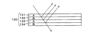
次に屈折率異方性を有する薄膜フィルムを3層以上の多層に積層する場合の構成を説明する。屈折率異方性を有する薄膜フィルムの積層数は2層に限定されない。図12は、屈折率異方性を有する薄膜フィルムを4層に重ねた例を示す模式図である。図13は、図12に示す積層構造の分解図である。
【0078】
図13に示す実施形態では、上から順に薄膜フィルムA、薄膜フィルムB、薄膜フィルムA、薄膜フィルムBと積層し、識別媒体130を構成している。各薄膜フィルムは屈折率異方性を有し、符号131および133で示される薄膜フィルムAでは、X軸方向の屈折率nAXとY軸方向の屈折率nAYとが異なっている。同様に符号132および134で示される薄膜フィルムBでは、X軸方向の屈折率nBXとY軸方向の屈折率nBYとが異なっている。また、符号131および133で示される薄膜フィルムAと符号132および134で示される薄膜フィルムBとは、そのX軸方向の屈折率は一致しているが、そのY軸方向の屈折率は相違している。つまり、nAX≠nAY、nBX≠nBY、nAX=nBX、nAY>nBYの関係が満たされている。
【0079】
この識別媒体130にX軸方向に偏光した光を照射すると、各薄膜フィルムのX軸方向における屈折率に差がないので、その光は識別媒体を透過する。他方で、この識別媒体130にY軸方向に偏光した光を照射すると、Y軸方向において、上下に隣接する薄膜フィルム間に屈折率の差が存在するので、その界面において反射が生じる。
【0080】
図14は、この反射が生じる原理を説明する図である。つまり、Y軸方向に偏光した光に対する屈折率は、薄膜フィルム131では屈折率nAYであり、薄膜フィルム132では屈折率nBYである。そして、上述のようにnAY≠nBYである。よって、Y軸方向に偏光した光は、薄膜フィルム131と薄膜フィルム132との界面において反射する。そしてこの反射が全反射でなければ、入射光の一部はさらに進み、次の薄膜フィルム132と薄膜フィルム133との界面において同様の原理によってさらに反射される。こうして、多段階に反射され、その反射光の干渉を見ることで、より強い反射光を認識できる。
【0081】
図12に例示するような構成とすると、複数の界面において反射が行われるので、反射光の強度を高めることができ、偏光方向の違う入射光に対する反射光の有無あるいはその強度の違いをより明確に認識できる。
【0082】
図12に例示する構成において、例えば薄膜フィルム132と133との間に、印刷や押出し加工によって図柄が付与された薄膜フィルムを挟んで配置してもよい。この場合、この挟んだ薄膜フィルムは可視光に対して透過性を有していることが必要である。
【0083】
図12〜14に例示する識別媒体は、ブルーシフトにより真贋を判定する方法に利用することもできる。ブルーシフトとは、屈折率の異なる積層フィルムを斜め方向から見た際に、層の界面から反射される反射光の干渉により、より低い角度(面に平行に近い方向)から積層フィルムを見る程、色が青みを帯びて(あるいは青っぽく)見える現象である。
【0084】
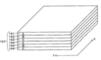
次に、3種以上の薄膜フィルムを積層する例を説明する。図15は、本発明の識別媒体の一例であり、3種類の薄膜フィルムを積層した構造を1単位として、それを2単位積層した構造を示す図である。図15には、符号161と164で示される薄膜フィルムA、符号162と165で示される薄膜フィルムB、および符号163と166で示される薄膜フィルムCが、ABCABCと6層に積層された識別媒体167が示されている。
【0085】
本実施形態では、各薄膜フィルムのX軸およびY軸方向における屈折率は一致しておらず、さらに上下に隣接する薄膜間において、X軸方向における屈折率の差がY軸方向における屈折率の差より大きくなるように、屈折率が設定されている。つまり、薄膜AのX軸方向の屈折率をnAX、薄膜AのY軸方向の屈折率をnAY、薄膜BのX軸方向の屈折率をnBX、薄膜BのY軸方向の屈折率をnBY、薄膜CのX軸方向の屈折率をnCX、薄膜CのY軸方向の屈折率をnCYとすると、
|nAX−nBX|>|nAY−nBY|
|nBX−nCX|>|nBY−nCY|
|nAX−nCX|>|nAY−nCY|
と設定されている。
【0086】
この構成では、Y軸方向に直線偏光した入射光を入射させた場合の反射光より、X軸方向に直線偏光した入射光を入射させた場合の反射光のほうが強くなる。なぜなら、各薄膜フィルム間における屈折率の差は、X軸方向における差の方がY軸方向における差より大きいからである。この反射光の強度の違いを利用することで、他の実施形態と同様に真贋判定を行うことができる。なお、ここでは全部で6層に積層する例を説明したが、例えば150層、あるいは200層といった多層構造を採用してもよい。
【0087】
本発明の識別媒体の他の例として、屈折率異方性を有する薄膜フィルムと屈折率に異方性の無い薄膜フィルムとの積層構造が挙げられる。図16は、屈折率異方性を有する薄膜フィルムと屈折率異方性を有しない薄膜フィルムとを積層した識別媒体の例を示す模式図である。図17は、図16の分解図である。
【0088】
図16および図17に示す実施形態では、屈折率異方性を有する薄膜フィルム141と屈折率異方性を有さない薄膜フィルム142とを積層して識別媒体140を構成している。
【0089】
屈折率異方性を有さない薄膜フィルム142は、XおよびY方向への延伸を同じように行うことで得ることができる。また、屈折率異方性を有さない薄膜フィルム142を得る方法として、超延伸、ブレンド法あるいは共重合法を用いることもできる。
【0090】
図16および図17に示す実施形態では、薄膜フィルム141のX軸方向における屈折率nAXと薄膜フィルム142のX軸方向における屈折率nBXとが一致し、薄膜フィルム141のY軸方向における屈折率nAYと薄膜フィルム142のY軸方向における屈折率nBYとが一致していない。
【0091】
この構成では、薄膜フィルム141側からX軸方向に偏光した光が入射した際には、薄膜フィルム141と薄膜フィルム142との界面において反射が生じず、薄膜フィルム141側からY軸方向に偏光した光が入射した際には、薄膜フィルム141と薄膜フィルム142との界面において反射が生じる。つまり、X軸方向に偏光した光にとっては、nAX=nBXであるので、薄膜フィルム141と薄膜フィルム142とは光学的には一体物であり、その間の界面が存在しないのと等価となるので、反射が生じず、逆にY軸方向に偏光した光にとっては、nAY≠nBYであるので、薄膜フィルム141と薄膜フィルム142との界面において、屈折率の違いに起因する反射が生じる。この反射の違いを観察することで、識別媒体140の真贋を判定することができる。
【0092】
なお、光の入射は、薄膜フィルム142側からであってもよい。また、図16に示す構造を基本として、3層以上の多層構造を構成してもよい。また、入射させる光を所定の方向に偏光させるのではなく、特定の偏光方向を有さない光を入射させ、偏光板を介してその反射光を観察するのでもよい。
【0093】
図16に示す構造において、薄膜フィルム142として光透過性を有する接着剤を利用することもできる。たとえば、硬化後において、薄膜フィルム141のX軸方向における屈折率nAXと同じ(あるいは近い)屈折率nBXを示す接着剤を薄膜フィルム141の一方の面に塗布し、この接着剤を硬化させることで、図16に示す構成と等価な構成が得られる。この構成を利用すると、薄膜フィルム141を適当な識別対象に上記性質を有する接着剤で貼り付け、その接着剤で構成される接着層142を薄膜フィルムとして機能させることができる。この場合、図17のX軸方向に偏光した光を薄膜フィルム141側から照射すると、その光は薄膜フィルム141と接着層142との界面で反射されず、接着層142の接着対象となる部材の表面が見える。他方で、Y軸方向に偏光した光を照射すると、薄膜フィルム141と接着層142との界面での反射が現れる。この違いを利用して識別力を得ることができる。
【0094】
本実施の形態において、nAXとnBXとを一致させない構成とすることもできる。この場合、|nAX−nBX|の値と|nAY−nBY|の値との間に差を設け、X軸方向に偏光した光の反射状態とY軸方向に偏光した光の反射状態との違いを見分ければよい。
【0095】
以上説明した識別媒体のバリエーションにおいて、判定の対称となる物品への識別媒体の固定は、接着剤による方法、粘着フィルムによる方法、ねじ止めやピン止め等による物理的な固定、透明シールで覆う方法、薄膜フィルム自体が有する接着力による方法等によって行うことができる。また、識別媒体の裏面側(光入射面の反対面)は、光吸収構造、光反射構造、あるいは光透過構造等を実施形態に合わせて任意に選択できる。
【0096】
光吸収構造というのは、識別媒体を透過した光を裏面側で吸収させる構造のことで、前述したように接着層中に光を吸収する黒等の顔料を混合した構造、あるいは裏面側の薄膜フィルムと接着層との間に光を吸収する黒色等の光吸収膜を配置した構造のことである。光反射構造というのは、識別媒体を透過した光を裏面側で反射させる構造で、たとえば裏面側の薄膜フィルムと接着層との間にアルミ箔等の反射膜を配置する構造、あるいは接着層中に反射材料の粉末を混合した構造のことである。光透過構造というのは、識別媒体を透過する光を裏面側で特に処理しない構造である。光透過構造の場合は、識別媒体を透過した光が識別媒体を貼り付けた基材の表面に到達するので、識別媒体を透過する光によって、識別媒体を介して基材の表面が見えることになる。この構成は、基材の表面の絵柄や模様が特定の偏光方向の光を照射することで浮かび上がる判定方法に利用することができる。
【0097】
図18は、本発明の識別媒体を備えた識別対象物品の例を示す模式図である。図18には、真贋判定の対象となるカード状の物品181、その表面に貼り付けられた識別媒体182が示されている。物品181としては、例えば会員証のカード、身分証明書、クレジットカード、定期券、その他偽造や変造が懸念されるカード状の物品が挙げられる。識別媒体182は、本発明を利用した識別媒体であり、例えば、本明細書中で例示した識別媒体を任意に適用できる。
【0098】
次に本発明の識別媒体を利用した真贋判定に用いる判定装置の実施形態を説明する。図19は、本発明の判定装置の実施形態を示すブロック図である。図19に示す判定装置は、光照射装置151、光検出装置152、制御装置153、情報出力装置154および偏光フィルタ155を備える。
【0099】
光照射装置151は、ランプや発光ダイオードでなる発光手段であり、特定の偏光方向に偏らない偏光状態の光を発生させる機能を有する。光照射装置151で発生した光は、照射光158として偏光フィルタ155を介して識別媒体157へ照射される。偏光フィルタ155は、一方向に偏光した光のみを優先的に透過させる機能を有し、図示しない回転機構により、照射光158の光軸を中心として回転できるようになっている。識別媒体157としては、たとえば本願明細書中で説明した構成のいずれかを採用できる。光検出装置152は、半導体の光起電力効果(光の照射によりPN接合等に起電力が生じる効果)や光伝導効果(光の照射によって半導体の導電率が変化する効果)を利用した光センサであり、識別媒体157からの反射光159を検出する。
【0100】
制御装置153は、光照射装置151の照射タイミングの制御、光検出装置152からの信号の処理、この処理結果の情報出力装置154への出力、および偏光フィルタ155の回転の制御を行う機能を備える。情報出力装置154は、識別媒体が贋物であるか否かの情報を音や表示等の適当な方法により出力する。
【0101】
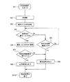
以下、図19の識別装置の動作例を説明する。図20は、本実施形態の識別装置を用いた贋物判定処理の流れの一例を示すフローチャートである。本実施形態では、図1に例示した識別媒体を黒い顔料を混合した接着剤で判定対象となる物品に貼り付けた状態において、その物品の真贋を判定する例を説明する。
【0102】
まず、識別媒体157が取り付けられた図示しない物品を図19に示す装置にセットし、入射光158が識別媒体157に照射できる状態とする。この状態で真贋判定処理を開始する(ステップS1)。最初に光照射装置151から光の照射を開始し(ステップS2)、ついで偏光フィルタ155を回転させる(ステップS3)。
【0103】
そして、光検出装置152で検出される反射光159の強度の変化を計測し、その値が最小になったか否かを判定する(ステップS4)。反射光159の値が最小になったら、偏光フィルタ155をその角度から90度回転させる(ステップS6)。
【0104】
他方で、反射光の最小値が見つからない場合は、S3の開始からの経過時間が所定の時間を経過したかを判定し(ステップS5)、所定の時間経過していれば異常信号の出力処理を行い(ステップS8)、情報出力装置154から判定対象の物品が正規の識別媒体を備えていなかった可能性が高い旨を警告する異常信号を出力する。ステップS5の判定において、所定の時間が経過していなければ、ステップS4の前段階に戻り、再度ステップS4を実行する。
【0105】
ステップS6の後、光検出装置152で検出された反射光159の強度とステップS4で検出した反射光159の最小値との差を比較し、その差が所定の差以上であるか否かを判定する(ステップS7)。所定の強度差が得られていれば、識別媒体157が正規の識別媒体である旨を示す正常信号を情報出力装置154から出力し(ステップS9)、所定の強度差が得られなければ、異常信号を情報出力装置154から出力する(ステップS8)。そして、判定処理を終了する(ステップS10)。
【0106】
図1の構成を採用した識別媒体であれば、図1のX軸方向に偏光した光を照射した場合はほとんど反射がなく、Y軸方向に偏光した光を照射した際には、それなりの反射が観察されるはずである。図20に例示する処理手順では、この反射光の強度差が所定以上であるかを判定し、識別媒体157が図1の構成を備えているか否かを判定する。なお、ステップS3を続けても反射光の強度に所定の変化が見られない場合、図1の構成を備えていないことが明白であるので、ステップS5において図1の構成を備えていないと判定され、異常信号が出力される。
【0107】
このようにして、識別媒体157が所定の構成を備えているか否かを判定することで、識別媒体157が贋物か否かの判定が行われ、それにより識別媒体157が取り付けられた物品の真贋を判定できる。
【0108】
図19に示す判定装置において、偏光フィルタを符号156の位置に配置し、反射光159の偏光方向を選択する構成としてもよい。この場合の判定手順は、図20のフローチャート示す手順と同じである。
【0109】
図19に示す判定装置では、偏光フィルタを回転させることで、識別媒体で反射されない(あるいは反射光の強度が最小になる)偏光の方向を自動的に検出する構成としている。しかし、識別媒体に照射すべき光の偏光方向が予め判明している場合は、偏光方向を直交させた2枚の偏光フィルタを用意し、それを切り替えて使用してもよい。このことは、偏光フィルタを符号156の位置に配置する場合でも同様である。また、光照射装置151として、直線偏光した光を直接発生する光発生手段(例えばレーザ光源)を用いてもよい。また、偏光フィルタを回転させる代わりに、識別媒体を回転させてもよい。
【00110】
次に図19の実施形態の判定装置によって、バーコードの読み取りを行う例を説明する。本実施形態は、真贋判定の対象となる物品の表面に印刷されたバーコードの読み取りに本発明を適用した例である。本実施形態では、真贋判定の対象となる物品の表面に所定の内容を示すバーコードを印刷し、その上に例えば図12に示す識別媒体を貼り付けておく。バーコードの内容は、例えば製造番号等である。他方で、図19に示す判定装置の光検出装置152としてバーコード読み取り装置を採用する。また、偏光フィルタ155を用いずに、偏光フィルタ156を用いる構造とし、被照射面を走査できるような構造としておく。
【0111】
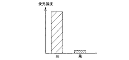
図21は、バーコード上に識別媒体を貼り付けない状態において、バーコードに光源からの光を照射し、その際におけるバーコードの黒部分と白部分における反射光の受光強度を示すグラフである。なお、図の縦軸は任意値である。また、ここで光源からの光は、特定の偏光方向に偏らない光であるとする。図22は、識別媒体をバーコード上に貼り付けた状態において、光源からの光を照射し、その反射光を観察した場合の受光強度を示すグラフである。図23は、識別媒体をバーコード上に貼り付けた状態において、光源から光を照射し、偏光フィルタを介してその反射光を観察した場合の受光強度を示すグラフである。
【0112】
図12に示す識別媒体を貼り付けた上述のバーコードに光照射装置151から光を照射し、偏光フィルタ156を介さずにその反射光を光検出装置152で受光すると、バーコードの白部分と黒部分のコントラストは図22に示すように小さくなる。これは、薄膜フィルムの境界面での反射光が存在するからである。つまり、バーコードの黒部分に到達すべき入射光の一部が識別媒体で反射されるので、黒部分からの反射光が、図1の場合に比較して強くなるからである。
【0113】
他方で、このバーコードに光照射装置151から光を照射し、その反射光を図12のX軸方向に偏光の向きを一致させた偏光フィルタ156を介して観察すると、黒部分からの反射強度が弱くなり、図23に示すようにバーコードの白と黒のコントラストを高く認識できる。これは、図12に例示する識別媒体ではX軸方向の屈折率が各薄膜フィルムで一致しているので、X軸方向の偏光は薄膜フィルム間の境界面で反射されず(あるいはあまり反射されず)、そのためX軸方向の偏光は、識別媒体で反射されずにバーコードの黒部分に到達し、そこで吸収されるからである。
【0114】
この原理を用いると、偏光フィルタを用いて特定の偏光を観察することでバーコードを読み取り可能で、他方で偏光フィルタを用いないとバーコードが読み取り困難となる技術が実現される。この技術は、真贋判定のみならず、特定方向の偏光の照射や、偏光フィルタを介しての観察を行わないと、読み取ることができない情報を商品や書類等に表示させておく技術に利用することができる。なお、本実施形態では、偏光でない光を照射し、偏光フィルタを介してその反射光を観察する場合を説明したが、偏光を照射する構成としてもよい。
【0115】
また本実施形態において、薄膜フィルムに回折格子パターンやエンボス加工を施し、バーコードパターンを読取り難くする技術を適用してもよい。また、バーコードを、識別媒体の裏面に印刷し、それを識別対象物品に貼り付けてもよい。また、ここではバーコードを読み取る例を説明したが、バーコード以外にOCR(Optical Character Recognition)で認識される文字、あるいは適当な模様や図柄等を認識対象として利用することもできる。
【0116】
本発明は、偽造を見破る技術に本発明を適用する以外に、ある製品が正規のルートを経ないで流通したことを見破る方法に適用することもできる。また、パスポートや重要書類等がしかるべき機関等で承認を受けているか否かを識別するのに利用することもできる。
【0117】
また本発明を利用することで、直接目視したのでは見え難い表示が、偏光フィルタを介することで見え易くなる識別媒体、あるいは自然光の照射(あるいは自然光のもと)では見え難い表示が偏光を照射することで見え易くなる識別媒体を得ることもできる。このような識別媒体は、玩具、機密保持、デザイン、消費者には見えないが特定の方法で見ることが可能な表示(例えば商品の管理番号等)等に利用可能することも可能である。
【0118】
【発明の効果】
本発明によれば、低コストで得られ、偽造され難く、温度変化や太陽光に当てる等の環境におかれても機能が低下しない真贋判定の技術が提供される。また、そのような技術に利用できる材料の製造技術が提供される。
【図面の簡単な説明】
【図1】本発明の識別媒体の一例を示す模式図である。
【図2】識別判定の原理を示す模式図である。
【図3】識別判定の原理を示す模式図である。
【図4】識別判定の原理を示す模式図である。
【図5】識別判定の原理を示す他の模式図である。
【図6】識別判定の原理を示す他の模式図である。
【図7】延伸の原理を示す模式図である。
【図8】屈折率と延伸率との関係を示すグラフである。
【図9】屈折率と延伸率との関係を示すグラフである。
【図10】屈折率と延伸率との関係を示すグラフである。
【図11】本発明の識別媒体の他の例を示す模式図である。
【図12】本発明の識別媒体の他の例を示す模式図である。
【図13】本発明の識別媒体の他の例を示す模式図である。
【図14】反射の原理を説明する図である。
【図15】本発明の識別媒体の他の例を示す模式図である。
【図16】本発明の識別媒体の他の例を示す模式図である。
【図17】本発明の識別媒体の他の例を示す模式図である。
【図18】本発明の識別媒体を備えた識別対象物品の例を示す模式図である。
【図19】本発明の判定装置の一例を示すブロック図である。
【図20】本発明の判定手順の一例を示すフローチャートである。
【図21】バーコードからの反射光の強度を示すグラフである。
【図22】バーコードからの反射光の強度を示すグラフである。
【図23】バーコードからの反射光の強度を示すグラフである。
【符号の説明】
101・・・薄膜フィルム、102・・・薄膜フィルム、103・・・識別媒体、104・・・入射光、105・・・入射光、110・・・入射光、111・・・反射光、112・・・透過光、113・・・偏光フィルタ、114・・・偏光方向、120・・・識別媒体、121・・・薄膜フィルム、122・・・薄膜フィルム、123・・・裏面フィルム、124・・・裏面、125・・・図柄、130・・・識別媒体、131・・・薄膜フィルム、132・・・薄膜フィルム、133・・・薄膜フィルム、134・・薄膜フィルム、140・・・識別媒体、141・・・薄膜フィルム、142・・薄膜フィルム、151・・・光照射装置、152・・・光検出装置、153・・・制御装置、154・・・情報出力装置、155・・・偏光フィルタ、156・・・偏光フィルタ、157・・・識別媒体、158・・・入射光、159・・・反射光、161・・・薄膜フィルム、162・・薄膜フィルム、163・・・薄膜フィルム、164・・・薄膜フィルム、165・・・薄膜フィルム、166・・・薄膜フィルム、167・・・識別媒体、181・・・カード状の物品、182・・・識別媒体、201・・・反射光、202・・・反射光。[0001]
TECHNICAL FIELD OF THE INVENTION
The present invention relates to a technology for determining the authenticity of various commodities, important documents, various IC cards, credit cards, cash vouchers, passports, banknotes, securities, or tickets using light reflection. Further, the present invention relates to a technique which is useful when applied to the manufacture of a laminate used for such authenticity judgment.
[0002]
[Prior art]
It is important to be able to determine whether or not the article is counterfeit as described above.
[0003]
As a method of making it easy to determine the authenticity of these products, stickers and prints that are not easy to forge and have a special appearance are attached to the object, and the seals and prints are visually recognized, so that legitimate manufacturing There is a method of determining whether a product is a product or not. As such a method, a method of attaching a hologram to the surface of an object or a method of applying a special ink is known (for example, see Patent Document 1).
[0004]
The method of using a hologram is a method of judging the authenticity of a hologram seal by using a phenomenon in which the color of a three-dimensional image looks different depending on the viewing angle. The method of using special ink is to apply the fluorescent ink or magnetic ink that looks like normal ink to the target visually, and to detect it by irradiating ultraviolet rays or a magnetic sensor to verify the authenticity of the target. This is a method of determining.
[0005]
Further, there is known a method of identifying authenticity by using the fact that the reflection characteristic of an identification medium using cholesteric liquid crystal depends on the viewing angle, and the state of reflected light slightly changes depending on the viewing angle (for example, Reference 2).
[0006]
[Patent Document 1]
JP 2001-315243 A (
[Patent Document 2]
Patent No. 3244278 (
[0007]
[Problems to be solved by the invention]
The method using a hologram has a problem in that the production of the hologram is expensive, and especially when a complicated hologram is produced in order to make counterfeiting difficult. The method using a fluorescent ink or a magnetic ink has a problem that counterfeiting is performed using similar inks or similar products, and an authentication effect cannot be obtained. The method of using cholesteric liquid crystal is that cholesteric liquid crystal is expensive and uneconomical, and there is a severe temperature change or deterioration or change of optical characteristics when exposed to sunlight, and stable performance is exhibited for a long time. I have anxiety.
[0008]
An object of the present invention is to provide a technology for authenticity determination that can be obtained at low cost, is hard to be forged, and does not deteriorate in function even in an environment such as temperature change or exposure to sunlight. Another object of the present invention is to provide a technique for producing a material that can be used for such a technique.
[0009]
[Means for Solving the Problems]
The identification medium of the present invention includes a light-transmitting first thin film having a refractive index anisotropy, and a light-transmitting second thin film laminated on the first thin film. In a first direction included in a first plane orthogonal to the thin film of the first thin film, the refractive index n of the first thin film 11 And the refractive index n of the second thin film 21 And is different.
[0010]
The present invention utilizes a phenomenon in which, when there is a difference in the refractive index between the laminated materials, the state of reflection at the interface between the materials differs depending on the difference. In other words, utilizing the principle that the reflectance R of light at the interface between materials having different refractive indices follows the Fresnel reflection of the following
[0011]
(Equation 1)
In
[0013]
When the thin films are stacked in multiple layers, components not reflected at the first interface are reflected at the next interface, and this phenomenon is repeated by the number of interfaces. Therefore, when it is assumed that the reflectance at one boundary surface is expressed by the
[0014]
(Equation 2)
According to the present invention, since the refractive index of the first thin film and the refractive index of the second thin film in the first direction included in the plane orthogonal to the first and second thin films are different, the first When light polarized in the direction is incident on the identification medium, reflection occurs at the interface between the two thin films. By observing the reflection, the identification medium can be identified.
[0016]
Here, the refractive index in a predetermined direction refers to the refractive index of the thin film with respect to linearly polarized light polarized in that direction. The refractive index anisotropy means that the refractive index has anisotropy depending on the direction. The reflection state refers to a state with or without reflection or a state of the intensity of reflected light. The light polarized in a predetermined direction refers to linearly polarized light having an amplitude direction of an electric field vector in a predetermined direction. Such light polarized in a predetermined direction can be obtained, for example, by passing natural light (light having a uniform polarization direction distribution including light in all polarization directions) through a polarizing plate (also referred to as a polarizer).
[0017]
The identification medium of the present invention can be obtained by laminating polymer thin films having refractive index anisotropy, and can be obtained without using special materials by devising a manufacturing method as described later. And cost reduction can be realized. In addition, since the identification medium of the present invention is a laminate of a polymer material thin film, it is not easy to estimate various setting parameters from a finished product, and it is possible to increase the difficulty of forgery. In addition, since it can be made of a material whose physical properties are hard to change under a normal environment, an identification medium with little change or deterioration in performance can be obtained even in a severe environment such as temperature change or exposure to sunlight.
[0018]
In the present invention, the refractive index n of the first thin film in a second direction included in a second surface different from the first surface 12 And the refractive index n of the second thin film 22 And | n 11 -N 21 | ≠ | n 12 -N 22 | Is preferable. According to such an embodiment, the reflection of light due to the difference in the refractive index between the thin films differs between the case of light linearly polarized in the first direction and the case of light linearly polarized in the second direction. It can be used for identification. To increase the discrimination ability, Δn 1 = | N 11 -N 21 |, Δn 2 = | N 12 -N 22 | As | Δn 1 −Δn 2 It is preferable to increase the value of | as much as possible to increase the difference in reflectance with respect to light having different polarization directions. Further, it is preferable that the first surface and the second surface are orthogonal to each other.
[0019]
In the present invention, it is preferable that the refractive index of the first thin film and the refractive index of the second thin film in the second direction included in the second surface orthogonal to the first surface match. According to such an embodiment, the light polarized in the second direction is not reflected at the interface between the first thin film and the second thin film, and is not reflected by the light polarized in the first direction reflected at the interface. The difference in the reflection state can be easily identified, and the identification medium can be easily identified.
[0020]
In the present invention, that the refractive indices coincide with each other means that the other coincides preferably within a range of ± 5%, more preferably within a range of ± 2%, and even more preferably within a range of ± 1%. Say.
[0021]
Further, in the present invention, the second thin film preferably has a refractive index anisotropy.
[0022]
Further, in the present invention, it is preferable that the identification determination is performed by comparing the reflection state of the incident light polarized in the first direction with the reflection state of the incident light polarized in a direction other than the first direction.
[0023]
Here, it is ideal that the direction of the first polarized light completely coincides with the direction of the polarized light of the incident light, but the range is within ± 10 degrees, preferably within ± 5 degrees in terms of angle. And more preferably within ± 1 °.
[0024]
In the present invention, it is preferable that the identification determination is performed by comparing the reflected light polarized in the first direction with the reflected light polarized in a direction other than the first direction.
[0025]
In the present invention, it is preferable that a third thin film is further provided, and the third thin film is subjected to printing, hologram processing, or embossing processing. Further, in the present invention, it is preferable that the first thin film and / or the second thin film have been subjected to hologram processing or embossing processing.
[0026]
The present invention can also be grasped as an article to be identified provided with the identification medium of the present invention. Examples of the article to be identified include various commodities, important documents, various IC cards, credit cards, cash vouchers, passports, bills, securities, stickers, tickets, and the like. These identification target articles may be printed with a logo, a lot number, a barcode, or the like, or may be provided with a pattern, pattern, hologram, or the like formed by unevenness or embossing. In this case, the symbols or the like formed by printing or processing are observed via the identification medium of the present invention.
[0027]
The determination device of the present invention includes a light-transmissive first thin film having a refractive index anisotropy, and a light-transmissive second thin film laminated on the first thin film. An apparatus for determining the authenticity of an identification medium in which a refractive index of a first thin film is different from a refractive index of a second thin film in a first direction included in a first surface orthogonal to the thin film of the identification medium; Light irradiating means for irradiating the light, light detecting means for detecting reflected light reflected from the identification medium, and a polarizing filter arranged in front of the light irradiating means and / or the light detecting means. Features. According to the determination device of the present invention, a determination device for determining the authenticity of the identification medium of the present invention is provided.
[0028]
In the determination device of the present invention, the polarizing filter has a function of transmitting the first light polarized in the first direction and a function of transmitting the second light polarized in a direction different from the first direction. Is preferred.
[0029]
The determination device of the present invention further includes a determination unit that performs identification determination by comparing the reflection state of the incident light polarized in the first direction with the reflection state of the incident light polarized in a direction other than the first direction. Preferably, it is provided.
[0030]
The determination device of the present invention preferably further includes a determination unit that performs identification determination by comparing the reflected light polarized in the first direction with the reflected light polarized in a direction other than the first direction.
[0031]
The determination method of the present invention includes a light-transmissive first thin film having a refractive index anisotropy, and a light-transmissive second thin film laminated on the first thin film. A method for determining the authenticity of an identification medium in which a refractive index of the first thin film and a refractive index of the second thin film are different in a first direction included in a first surface orthogonal to the second thin film. A light irradiation step of irradiating the identification medium with light, and a light detection step of detecting reflected light reflected from the identification medium, wherein the light irradiation step includes irradiating light through a polarizing filter in the light irradiation step. Detecting the reflected light in the light irradiating step, or irradiating natural light as it is in the light irradiating step, and detecting the reflected light via a polarizing filter in the light detecting step, or detecting the reflected light in the light irradiating step. Filter through a polarizing filter in the light detecting step is irradiated with light through and detects the reflected light.
[0032]
In the method for producing a laminate of the present invention, a step of laminating a first material having a positive refractive index change in the stretching direction and a second material having a negative refractive index change in the stretching direction to obtain a laminate And a step of stretching the laminate in the predetermined direction until the refractive index in the predetermined direction matches between the first material and the second material.
[0033]
According to the lamination method of the present invention, the identification medium of the present invention can be manufactured. Hereinafter, the principle of the lamination method of the present invention will be described. Generally, when a thin film made of a polymer material is manufactured by stretching, the refractive index in the stretching direction changes according to the stretching rate. Here, the stretching ratio P is determined by P = (L ′ / L), where L is the dimension before stretching in the stretching direction and L ′ is the dimension after stretching. The stretching ratio is also called a stretching ratio or a stretching ratio. Further, the change in the refractive index (hereinafter referred to as Δn) is a material that takes a positive value when stretched (ie, a material whose refractive index increases by stretching) and a material that takes a negative value when stretched in the opposite direction. (That is, a material whose refractive index decreases by stretching). For example, when PVC (polyvinyl chloride) is stretched, the refractive index increases (Δn is positive), and when PMMA (acrylic) is stretched, the refractive index decreases (Δn is negative).
[0034]
FIG. 8 is a graph showing an example of a change in refractive index in the stretching direction of two polymer materials according to stretching. FIG. 8 shows a change in the refractive index of the polymer material A in which Δn is negative and a change in the refractive index of the polymer material B in which Δn is positive. Note that the vertical axis in FIG. 8 is an arbitrary value indicating the relative relationship between the refractive indexes, and the horizontal axis is an arbitrary value indicating the relative relationship between the stretching ratios.
[0035]
For example, a polymer material A and a polymer material B illustrated in FIG. 8 are laminated, and the laminate is stretched in one direction (for example, the X axis). As the stretching proceeds, the refractive index of the material A in the X-axis direction decreases with stretching, and the refractive index of the material B in the X-axis direction increases with stretching. The refractive index of both materials becomes the same at the point indicated by the stretching ratio α. On the other hand, when the film is stretched in the Y-axis direction perpendicular to the X-axis direction to the stretching ratio β, the refractive index in the Y-axis direction becomes a different value between the two thin films. By controlling the stretching ratio in this way, it is possible to obtain a laminate composed of the material A and the material B whose refractive indices match in the X-axis direction but do not match in the Y-axis direction. This method utilizes a change in optical properties according to stretching of a material, and does not require a special material or method, and has an advantage of low cost.
[0036]
Another manufacturing method of a laminate according to the present invention includes laminating a first material whose refractive index does not change in the direction of stretching by stretching and a second material whose refractive index changes in the direction of stretching by stretching. A step of obtaining the laminated body, and a step of stretching the laminated body in the predetermined direction until the refractive index in a predetermined direction matches the refractive index of the first material and the second material. And
[0037]
According to another lamination method of the present invention, the identification medium of the present invention can be manufactured. The principle of another lamination method of the present invention will be described. As described above, when a polymer material is stretched in a certain direction, the refractive index in that direction changes.However, when stretching is performed at a certain temperature specific to the material, a change in the refractive index due to stretching is not observed. Alternatively, a phenomenon in which the change is small is observed. This phenomenon is due to the fact that orientation and crystallization by stretching are not promoted at a certain temperature, and no change in the refractive index in the stretching direction appears. This phenomenon is called super drawing (super elongation). The temperature at which super-stretching occurs generally depends on the material, and is, for example, 110 ° C. to 120 ° C. in the case of PET (polyethylene terephthalate).
[0038]
For example, when a laminated structure of the polymer material A and the polymer material B is stretched, the material A is stretched at a temperature at which the material A does not exhibit super-stretching and the material B exhibits super-stretching, whereby the refraction in the stretching direction of the material B is performed. The refractive index in the stretching direction of the material A can be changed without changing the refractive index.
[0039]
FIG. 9 is a graph showing a change in the refractive index when one material shows super-stretching and the other material stretches at a temperature not showing super-stretching. FIG. 10 is a graph showing a change in the refractive index when one of the materials is stretched at a temperature that does not exhibit super-stretching while the other material does not exhibit super-stretching. The meanings of the vertical and horizontal axes in FIGS. 9 and 10 are the same as those in FIG.
[0040]
In the case of FIG. 9, the refractive index of the material A in the stretching direction does not change even when the stretching is performed, but the refractive index of the material B in the stretching direction increases with the stretching. Therefore, at the time when the stretching has progressed to some extent and reaches α, the refractive indices of the material A and the material B in the stretching direction match.
[0041]
When the material A is stretched at a temperature at which the material B exhibits super-stretching, the relationship shown in FIG. 10 is obtained. In this case, when the stretching ratio at which the stretching has progressed to some extent is α, the stretching ratios of the material A and the material B in the stretching direction match.
[0042]
By utilizing this phenomenon, two types of thin films are laminated and stretched at a certain temperature, so that the refractive indices of the two thin films match in a certain direction, and the refractive indices differ in a direction perpendicular to the direction. A thin film laminated material can be obtained. This method also has the advantage that it can be realized at low cost.
[0043]
In addition to the method using the above-described super-stretching, a method using a blending method and a copolymerization method is a method that can obtain a similar effect. The blending method is a technique for obtaining a thin film from a material obtained by mixing a material having a positive refractive index change according to stretching and a material having a negative refractive index according to stretching. This is a technique for obtaining a thin film in which a change in the refractive index in the stretching direction does not appear (or hardly changes). The copolymerization method is a technique for canceling polarization anisotropy by randomizing the orientation of monomers constituting a polymer chain so that macroscopic refractive index anisotropy does not appear even when stretching is performed. .
[0044]
BEST MODE FOR CARRYING OUT THE INVENTION
Hereinafter, embodiments of the present invention will be described in detail. First, it has a structure in which two thin films having refractive index anisotropy in a plane direction are laminated, and the refractive indices in a predetermined direction (tentatively, an X-axis direction) in the plane coincide with each other. An example of an identification medium in which the refractive indexes do not match in a direction perpendicular to the direction (tentatively, the Y-axis direction) will be described.
[0045]
FIG. 1 is a schematic diagram showing a basic structure of the identification medium of the present embodiment. FIG. 1 shows an
[0046]
The
[0047]
Hereinafter, the function of the identification medium illustrated in FIG. 1 will be described. FIG. 2 is a schematic diagram showing a state in which
[0048]
This is the refractive index n of the
[0049]
FIG. 3 is a schematic diagram illustrating a state in which
[0050]
This is because the refractive index in the
[0051]
In this way, by making the light incident on the
[0052]
For example, by irradiating the incident lights 104 and 105 individually and observing the state where the
[0053]
As an example of the case where the identification medium having the structure illustrated in FIG. 1 is used as a means for authenticity determination, there is an example in which the
[0054]
In this configuration, the authenticity is determined as follows. First, when linearly polarized light, such as
[0055]
Further, in the structure illustrated in FIG. 1, one or both of the
[0056]
Here, an example in which the incident light is linearly polarized light has been described, but the incident light may be natural light, and the reflected light may be observed through a polarizing filter.
[0057]
This example will be described below. FIG. 4 is a schematic diagram illustrating an example in which reflected light of natural light is observed via a polarizing filter. When
[0058]
In the configuration shown in FIG. AX ≠ n BX And n AX And n BX N AY And n BY And a difference in reflection intensity at the interface between the
[0059]
Hereinafter, this example will be described. FIG. 5 and FIG. 6 are other schematic diagrams illustrating the principle of identification determination. FIGS. 5 and 6 show two thin film A (upper) and thin film B (lower) having refractive index anisotropy laminated like the
[0060]
In this configuration, as shown in FIG. 5, when light 104 linearly polarized in the X-axis direction enters the
[0061]
Next, a method for manufacturing the identification medium illustrated in FIG. 1 will be described. The
[0062]
Here, an example will be described in which the principle shown in FIG. 8 is used to obtain a laminated structure in which the refractive indices match on the X-axis and the refractive indices do not match on the Y-axis as illustrated in FIG.
[0063]
The materials used are polystyrene and polyvinyl chloride. First, both materials are molded into a plate shape by extrusion molding, and further, the two materials are biaxially stretched by a biaxial stretching device in a state where they are stacked.
[0064]
In the present embodiment, the stretching conditions of the biaxial stretching device are adjusted so that the stretching ratio in the X-axis direction is α = 2.4 and the stretching ratio in the Y-axis direction is β = 1.2. A laminate (corresponding to 103 in FIG. 1) of a polystyrene thin film corresponding to 101 and a polyvinyl chloride thin film corresponding to 102 in FIG. 1 is obtained. Here, as the value of β, it is preferable to select a value that can ensure the difference in the refractive index as large as possible.
[0065]
Thus, a laminated thin film in which the refractive indices of both thin films match in the X-axis direction and the refractive indices of both thin films do not match in the Y-axis direction orthogonal to the X-axis direction, as illustrated in FIG.
[0066]
Next, an example of manufacturing an identification medium as illustrated in FIG. 1 by utilizing the super-stretching phenomenon will be described. Hereinafter, an example of manufacturing an identification medium having the structure illustrated in FIG. 1 using the relationship illustrated in FIG. 10 will be described.
[0067]
First, a polyethylene terephthalate (PET) corresponding to the material B and a polystyrene (PS) corresponding to the material A are extruded and molded into a plate shape. It is biaxially stretched while maintaining it.
[0068]
In this embodiment, the stretching conditions are adjusted such that the value of the stretching rate in the X-axis direction is α = 1.8 and the stretching rate in the Y-axis direction is γ = 4.0, and corresponds to 101 in FIG. A laminate (corresponding to 103 in FIG. 1) of a thin film composed of polyethylene terephthalate (material B in FIG. 10) and a thin film composed of polystyrene (material A in FIG. 10) corresponding to 102 in FIG. 1 is obtained. In these embodiments, it is necessary to experimentally determine the value of α in advance.
[0069]
In this way, a laminated thin film in which the refractive indices of both thin films match in the X-axis direction and the refractive indices of both thin films do not match in the Y-axis direction orthogonal to the X-axis direction is obtained.
[0070]
In the above-described embodiment, an example in which a laminated film of polyethylene terephthalate and polystyrene is stretched at a temperature at which polyethylene terephthalate exhibits super-stretching, using the relationship of FIG. However, the stretching may be performed at a temperature at which polystyrene exhibits super-stretching, using the principle shown in FIG. In order to obtain the identification medium having the configuration illustrated in FIGS. 5 and 6, in the above-described manufacturing method, two values of β are set so that two types of differences in the refractive index depending on the stretching ratio can be obtained. Good.
[0071]
Next, various variations of the identification medium of the present invention will be described. FIG. 11 is a schematic diagram showing another embodiment utilizing the present invention. FIG. 11 shows an
[0072]
By irradiating the
[0073]
On the other hand, when the polarization direction of the polarizing filter coincides with the Y axis, there is reflection between the
[0074]
The
[0075]
FIG. 11 shows an example in which the
[0076]
Further, embossing, embossing or hologram processing may be performed on the thin film itself. The printing, embossing, embossing, or hologram processing as described above may be performed directly on the object to which the identification medium is to be attached.
[0077]
Next, a structure in which three or more thin film films having refractive index anisotropy are laminated will be described. The number of laminated thin film films having the refractive index anisotropy is not limited to two. FIG. 12 is a schematic diagram showing an example in which four thin film layers having refractive index anisotropy are stacked. FIG. 13 is an exploded view of the laminated structure shown in FIG.
[0078]
In the embodiment shown in FIG. 13, the thin film A, the thin film B, the thin film A, and the thin film B are laminated in this order from the top to form the
[0079]
When the
[0080]
FIG. 14 is a diagram illustrating the principle of this reflection. That is, the refractive index for light polarized in the Y-axis direction is n AY And the refractive index n in the
[0081]
With the configuration as illustrated in FIG. 12, since reflection is performed at a plurality of interfaces, the intensity of reflected light can be increased, and the presence or absence of reflected light with respect to incident light having a different polarization direction or the difference in the intensity can be more clearly determined. Can be recognized.
[0082]
In the configuration illustrated in FIG. 12, for example, a thin film provided with a design by printing or extrusion may be interposed between the
[0083]
The identification media illustrated in FIGS. 12 to 14 can also be used for a method of determining authenticity by blue shift. Blue shift means that when a laminated film having a different refractive index is viewed from an oblique direction, interference of reflected light reflected from an interface between layers causes interference of reflected light, so that the laminated film is viewed from a lower angle (a direction closer to parallel to a surface). This is a phenomenon in which the color looks bluish (or bluish).
[0084]
Next, an example in which three or more types of thin film are laminated will be described. FIG. 15 is an example of the identification medium of the present invention, and is a diagram showing a structure in which a structure in which three types of thin film are laminated is regarded as one unit and two units are laminated. FIG. 15 shows an identification medium in which a thin film A denoted by
[0085]
In the present embodiment, the refractive indices in the X-axis and Y-axis directions of each thin film do not match, and the difference between the refractive indices in the X-axis direction between the vertically adjacent thin films is the refractive index in the Y-axis direction. The refractive index is set so as to be larger than the difference. That is, the refractive index of the thin film A in the X-axis direction is n AX , The refractive index of the thin film A in the Y-axis direction is n AY , The refractive index of the thin film B in the X-axis direction is n BX , The refractive index of the thin film B in the Y-axis direction is n BY , The refractive index of the thin film C in the X-axis direction as n CX , The refractive index of the thin film C in the Y-axis direction is n CY Then
| N AX -N BX |> | N AY -N BY |
| N BX -N CX |> | N BY -N CY |
| N AX -N CX |> | N AY -N CY |
Is set.
[0086]
In this configuration, the reflected light when the incident light linearly polarized in the X-axis direction is stronger than the reflected light when the incident light linearly polarized in the Y-axis direction is incident. This is because the difference in refractive index between the thin films is larger in the X-axis direction than in the Y-axis direction. By utilizing the difference in the intensity of the reflected light, it is possible to determine the authenticity as in the other embodiments. Although an example in which six layers are stacked in total has been described here, a multilayer structure of, for example, 150 layers or 200 layers may be adopted.
[0087]
Another example of the identification medium of the present invention includes a laminated structure of a thin film having a refractive index anisotropy and a thin film having no anisotropy in a refractive index. FIG. 16 is a schematic diagram showing an example of an identification medium in which a thin film having a refractive index anisotropy and a thin film having no refractive index anisotropy are laminated. FIG. 17 is an exploded view of FIG.
[0088]
In the embodiment shown in FIGS. 16 and 17, the
[0089]
The
[0090]
In the embodiment shown in FIGS. 16 and 17, the refractive index n of the
[0091]
In this configuration, when light polarized in the X-axis direction is incident from the
[0092]
The light may be incident from the
[0093]
In the structure shown in FIG. 16, an adhesive having a light transmitting property can be used as the
[0094]
In the present embodiment, n AX And n BX May not be matched. In this case, | n AX -N BX | Value and | n AY -N BY The difference between the reflection state of the light polarized in the X-axis direction and the reflection state of the light polarized in the Y-axis direction can be distinguished from each other by providing a difference between the |
[0095]
In the above-described variations of the identification medium, the fixing of the identification medium to the article to be symmetrically determined is performed by a method using an adhesive, a method using an adhesive film, a physical fixing using screws or pins, and a method using a transparent seal. It can be performed by a method based on the adhesive force of the thin film itself. On the back side of the identification medium (the surface opposite to the light incident surface), a light absorbing structure, a light reflecting structure, a light transmitting structure, or the like can be arbitrarily selected according to the embodiment.
[0096]
The light-absorbing structure is a structure that absorbs light transmitted through the identification medium on the back side, and a structure in which a pigment such as black that absorbs light is mixed in the adhesive layer as described above, or a thin film on the back side This is a structure in which a light absorbing film of black or the like that absorbs light is arranged between the film and the adhesive layer. The light reflection structure is a structure in which light transmitted through the identification medium is reflected on the back surface side. For example, a structure in which a reflection film such as an aluminum foil is disposed between the thin film on the back side and the adhesion layer, or a structure in which the reflection layer is formed. Is a structure in which a powder of a reflective material is mixed. The light transmission structure is a structure in which light transmitted through the identification medium is not particularly processed on the back surface side. In the case of the light transmitting structure, the light transmitted through the identification medium reaches the surface of the base material to which the identification medium is attached, so that the light transmitted through the identification medium allows the surface of the base material to be seen through the identification medium. Become. This configuration can be used for a determination method in which a picture or pattern on the surface of the base material emerges by irradiating light with a specific polarization direction.
[0097]
FIG. 18 is a schematic diagram illustrating an example of an identification target article provided with the identification medium of the present invention. FIG. 18 shows a card-shaped
[0098]
Next, an embodiment of a judgment apparatus used for authenticity judgment using the identification medium of the present invention will be described. FIG. 19 is a block diagram showing an embodiment of the determination device of the present invention. The determination device illustrated in FIG. 19 includes a
[0099]
The
[0100]
The
[0101]
Hereinafter, an operation example of the identification device of FIG. 19 will be described. FIG. 20 is a flowchart illustrating an example of the flow of a counterfeit determination process using the identification device of the present embodiment. In the present embodiment, an example will be described in which the authenticity of an article is determined in a state where the identification medium illustrated in FIG. 1 is adhered to an article to be determined using an adhesive mixed with a black pigment.
[0102]
First, an article (not shown) to which the
[0103]
Then, a change in the intensity of the reflected light 159 detected by the
[0104]
On the other hand, if the minimum value of the reflected light is not found, it is determined whether or not the elapsed time from the start of S3 has exceeded a predetermined time (step S5). If the predetermined time has elapsed, an abnormal signal output process is performed. (Step S8), and outputs an abnormal signal from the
[0105]
After step S6, the difference between the intensity of the reflected light 159 detected by the
[0106]
In the case of the identification medium adopting the configuration of FIG. 1, there is almost no reflection when the light polarized in the X-axis direction in FIG. 1 is irradiated, and there is a certain reflection when the light polarized in the Y-axis direction is irradiated. Should be observed. In the processing procedure illustrated in FIG. 20, it is determined whether or not the difference in the intensity of the reflected light is equal to or more than a predetermined value, and whether or not the
[0107]
In this manner, by determining whether or not the
[0108]
In the determination device shown in FIG. 19, a configuration may be adopted in which the polarization filter is disposed at the position of
[0109]
The determination device shown in FIG. 19 is configured to automatically detect the direction of polarized light that is not reflected by the identification medium (or minimizes the intensity of reflected light) by rotating the polarizing filter. However, when the polarization direction of the light to be applied to the identification medium is known in advance, two polarization filters having the polarization directions orthogonal to each other may be prepared and used by switching between them. This is the same even when the polarization filter is arranged at the position of
[00110]
Next, an example in which a barcode is read by the determination device of the embodiment of FIG. 19 will be described. This embodiment is an example in which the present invention is applied to reading of a barcode printed on the surface of an article to be authenticated. In the present embodiment, a bar code indicating a predetermined content is printed on the surface of an article to be authenticated, and an identification medium shown in FIG. 12 is attached thereon. The content of the barcode is, for example, a serial number. On the other hand, a bar code reading device is employed as the
[0111]
FIG. 21 is a graph showing the light receiving intensity of the reflected light in the black portion and the white portion of the bar code when the bar code is irradiated with light from a light source in a state where the identification medium is not pasted on the bar code. . The vertical axis in the figure is an arbitrary value. Here, it is assumed that the light from the light source is light that is not biased in a specific polarization direction. FIG. 22 is a graph showing the received light intensity when the light from the light source is irradiated and the reflected light is observed in a state where the identification medium is stuck on the barcode. FIG. 23 is a graph showing the received light intensity when light is emitted from a light source and the reflected light is observed through a polarizing filter in a state where the identification medium is stuck on the barcode.
[0112]
When the above-described barcode to which the identification medium shown in FIG. 12 is attached is irradiated with light from the
[0113]
On the other hand, when the bar code is irradiated with light from the
[0114]
By using this principle, a technique is realized in which a bar code can be read by observing specific polarized light using a polarizing filter, while reading the bar code is difficult without using a polarizing filter. This technology should be used not only for authenticity determination but also for displaying information on products or documents that cannot be read without irradiating polarized light in a specific direction or observing through a polarizing filter. Can be. In the present embodiment, the case where non-polarized light is irradiated and the reflected light is observed through the polarizing filter has been described. However, a configuration in which polarized light is irradiated may be used.
[0115]
Further, in the present embodiment, a technique may be applied in which a thin film is subjected to a diffraction grating pattern or embossing to make it difficult to read a barcode pattern. Further, a barcode may be printed on the back surface of the identification medium, and the barcode may be attached to the article to be identified. Although an example in which a barcode is read has been described here, a character recognized by OCR (Optical Character Recognition) or an appropriate pattern or pattern other than the barcode can be used as a recognition target.
[0116]
In addition to applying the present invention to a technology for detecting forgery, the present invention can also be applied to a method for detecting that a product has been distributed without going through a legitimate route. It can also be used to identify whether passports, important documents, etc. have been approved by an appropriate institution.
[0117]
In addition, by using the present invention, a display medium that is difficult to see when viewed directly, but an identification medium that is easy to see through a polarizing filter, or a display that is hard to see when irradiated with natural light (or under natural light) emits polarized light. By doing so, it is also possible to obtain an identification medium that can be easily seen. Such an identification medium can also be used for toys, confidentiality, designs, displays that are invisible to consumers but can be viewed in a specific manner (for example, product management numbers, etc.).
[0118]
【The invention's effect】
ADVANTAGE OF THE INVENTION According to this invention, the technology of the authenticity determination which is obtained at low cost, is hard to be forged, and does not lose its function even in an environment such as temperature change or exposure to sunlight is provided. Further, a technique for manufacturing a material that can be used for such a technique is provided.
[Brief description of the drawings]
FIG. 1 is a schematic diagram showing an example of an identification medium of the present invention.
FIG. 2 is a schematic diagram illustrating the principle of identification determination.
FIG. 3 is a schematic diagram illustrating the principle of identification determination.
FIG. 4 is a schematic diagram showing the principle of identification determination.
FIG. 5 is another schematic diagram illustrating the principle of identification determination.
FIG. 6 is another schematic diagram illustrating the principle of identification determination.
FIG. 7 is a schematic view showing the principle of stretching.
FIG. 8 is a graph showing a relationship between a refractive index and a stretching ratio.
FIG. 9 is a graph showing a relationship between a refractive index and a stretching ratio.
FIG. 10 is a graph showing a relationship between a refractive index and a stretching ratio.
FIG. 11 is a schematic diagram showing another example of the identification medium of the present invention.
FIG. 12 is a schematic diagram showing another example of the identification medium of the present invention.
FIG. 13 is a schematic diagram showing another example of the identification medium of the present invention.
FIG. 14 is a diagram illustrating the principle of reflection.
FIG. 15 is a schematic diagram showing another example of the identification medium of the present invention.
FIG. 16 is a schematic diagram showing another example of the identification medium of the present invention.
FIG. 17 is a schematic diagram showing another example of the identification medium of the present invention.
FIG. 18 is a schematic diagram illustrating an example of an identification target article provided with the identification medium of the present invention.
FIG. 19 is a block diagram illustrating an example of a determination device of the present invention.
FIG. 20 is a flowchart illustrating an example of a determination procedure according to the present invention.
FIG. 21 is a graph showing the intensity of reflected light from a bar code.
FIG. 22 is a graph showing the intensity of light reflected from a bar code.
FIG. 23 is a graph showing the intensity of reflected light from a bar code.
[Explanation of symbols]
101 thin film, 102 thin film, 103 identification medium, 104 incident light, 105 incident light, 110 incident light, 111 reflected light, 112 ... transmitted light, 113 ... polarization filter, 114 ... polarization direction, 120 ... identification medium, 121 ... thin film, 122 ... thin film, 123 ... back film, 124 ... ..Backside, 125 ... design, 130 ... identification medium, 131 ... thin film, 132 ... thin film, 133 ... thin film, 134 ... thin film, 140 ... identification medium .. 141 thin film, 142 thin film, 151 light irradiation device, 152 light detection device, 153 control device, 154 information output device, 155 polarization Filter, 156: Polarizing filter, 157: Identification medium, 158: Incident light, 159: Reflected light, 161: Thin film, 162: Thin film, 163: Thin film, 164: thin film, 165: thin film, 166: thin film, 167: identification medium, 181: card-shaped article, 182: identification medium, 201: reflected light , 202... Reflected light.
Claims (14)
前記第1の薄膜と積層された光透過性の第2の薄膜と
を備え、
前記第1および第2の薄膜に直交する第1の面に含まれる第1の方向において、前記第1の薄膜の屈折率n11と前記第2の薄膜の屈折率n21とが異なることを特徴とする識別媒体。A light-transmissive first thin film having refractive index anisotropy;
A light-transmitting second thin film laminated with the first thin film;
In a first direction included in a first plane perpendicular to said first and second thin film, said a first refractive index n 21 and the refractive index n 11 of the second thin film are different Characteristic identification medium.
|n11−n21|≠|n12−n22|であることを特徴とする請求項1に記載の識別媒体。In a second direction included in the first surface is different from a second plane, different from the a first thin film having a refractive index n 12 and the second thin film having a refractive index n 22 is,
| N 11 -n 21 | ≠ | identification medium according to claim 1, characterized in that a is | n 12 -n 22.
前記識別媒体に光を照射する光照射手段と、
前記識別媒体から反射した反射光を検出する光検出手段と、
前記光照射手段または/および前記光検出手段の前に配置された偏光フィルタと
を備えることを特徴とする判定装置。A light-transmitting first thin film having a refractive index anisotropy; and a light-transmitting second thin film laminated on the first thin film, wherein a first light-transmitting thin film is orthogonal to the first and second thin films. An apparatus for performing authenticity determination of an identification medium in which a refractive index of the first thin film is different from a refractive index of the second thin film in a first direction included in the first surface,
Light irradiation means for irradiating the identification medium with light,
Light detection means for detecting reflected light reflected from the identification medium,
A determination device comprising: a light-emitting unit and / or a polarizing filter disposed before the light-detecting unit.
前記第1の方向に偏光した第1の光を透過する機能と、
前記第1の方向と異なる方向に偏光した第2の光を透過する機能と
を備えることを特徴とする請求項8に記載の判定装置。The polarizing filter,
A function of transmitting the first light polarized in the first direction;
The apparatus according to claim 8, further comprising a function of transmitting a second light polarized in a direction different from the first direction.
前記識別媒体に光を照射する光照射ステップと、
前記識別媒体から反射した反射光を検出する光検出ステップと
を備え、
前記光照射ステップにおいて偏光フィルタを介して光を照射し前記光検出ステップにおいてその反射光を検出すること、または前記光照射ステップにおいて自然光をそのまま照射し前記光検出ステップにおいて偏光フィルタを介してその反射光を検出すること、または前記光照射ステップにおいて偏光フィルタを介して光を照射し前記光検出ステップにおいて偏光フィルタを介してその反射光を検出することを特徴とする識別媒体の判定方法。A light-transmitting first thin film having a refractive index anisotropy; and a light-transmitting second thin film laminated on the first thin film, wherein a first light-transmitting thin film is orthogonal to the first and second thin films. A method for performing authenticity determination of an identification medium in which a refractive index of the first thin film is different from a refractive index of the second thin film in a first direction included in the first surface,
A light irradiation step of irradiating the identification medium with light,
Comprising a light detection step of detecting reflected light reflected from the identification medium,
Irradiating light through a polarization filter in the light irradiation step and detecting the reflected light in the light detection step, or irradiating natural light as it is in the light irradiation step and reflecting the light through a polarization filter in the light detection step A method for determining an identification medium, comprising detecting light, or irradiating light through a polarizing filter in the light irradiating step, and detecting reflected light thereof through a polarizing filter in the light detecting step.
所定の方向における屈折率が前記第1の材料と前記第2の材料とにおいて一致するまで、前記積層体を前記所定の方向に延伸する工程と
を備えることを特徴とする積層体の製造方法。A step of laminating a first material having a positive refractive index change in the stretching direction and a second material having a negative refractive index change in the stretching direction to obtain a laminate;
Stretching the laminate in the predetermined direction until the refractive index in the predetermined direction matches the refractive index of the first material and the second material.
所定の方向における屈折率が前記第1の材料と前記第2の材料とにおいて一致するまで、前記積層体を前記所定の方向に延伸する工程と
を備えることを特徴とする積層体の製造方法。A step of laminating a first material whose refractive index does not change in the direction of stretching by stretching and a second material whose refractive index changes in the direction of stretching by stretching, to obtain a laminate;
Stretching the laminate in the predetermined direction until the refractive index in the predetermined direction matches the refractive index of the first material and the second material.
Priority Applications (1)
| Application Number | Priority Date | Filing Date | Title |
|---|---|---|---|
| JP2003148659A JP2004354430A (en) | 2003-05-27 | 2003-05-27 | Discrimination medium, articles to be discriminated, judging device, judging method of discrimination medium and manufacturing method of laminated body |
Applications Claiming Priority (1)
| Application Number | Priority Date | Filing Date | Title |
|---|---|---|---|
| JP2003148659A JP2004354430A (en) | 2003-05-27 | 2003-05-27 | Discrimination medium, articles to be discriminated, judging device, judging method of discrimination medium and manufacturing method of laminated body |
Publications (1)
| Publication Number | Publication Date |
|---|---|
| JP2004354430A true JP2004354430A (en) | 2004-12-16 |
Family
ID=34044963
Family Applications (1)
| Application Number | Title | Priority Date | Filing Date |
|---|---|---|---|
| JP2003148659A Pending JP2004354430A (en) | 2003-05-27 | 2003-05-27 | Discrimination medium, articles to be discriminated, judging device, judging method of discrimination medium and manufacturing method of laminated body |
Country Status (1)
| Country | Link |
|---|---|
| JP (1) | JP2004354430A (en) |
Cited By (2)
| Publication number | Priority date | Publication date | Assignee | Title |
|---|---|---|---|---|
| JP2007276444A (en) * | 2006-03-17 | 2007-10-25 | Ricoh Co Ltd | Identification device, and identification medium |
| JP2008139510A (en) * | 2006-11-30 | 2008-06-19 | Toppan Printing Co Ltd | Layered body, adhesive label, recording medium, article with label and discrimination method |
-
2003
- 2003-05-27 JP JP2003148659A patent/JP2004354430A/en active Pending
Cited By (2)
| Publication number | Priority date | Publication date | Assignee | Title |
|---|---|---|---|---|
| JP2007276444A (en) * | 2006-03-17 | 2007-10-25 | Ricoh Co Ltd | Identification device, and identification medium |
| JP2008139510A (en) * | 2006-11-30 | 2008-06-19 | Toppan Printing Co Ltd | Layered body, adhesive label, recording medium, article with label and discrimination method |
Similar Documents
| Publication | Publication Date | Title |
|---|---|---|
| US7943392B2 (en) | Discrimination medium, discrimination method, article to be discriminated, and discrimination apparatus | |
| EP1798026B1 (en) | Discrimination medium | |
| CA2308466C (en) | Genuineness detecting system and method for using genuineness detecting film | |
| JP4778445B2 (en) | Identification medium, article provided with identification medium, and identification method | |
| JP4392826B2 (en) | Object identification medium and identification method | |
| US8168080B2 (en) | Identifying medium, identifying medium manufacturing method, article, and identifying medium identifying method | |
| EP1475766B1 (en) | Identifying medium and identifying method for object | |
| WO2013103639A1 (en) | Effective media retarder films with spatially selective birefringence reduction | |
| JP4565541B2 (en) | Identification medium and article to be identified | |
| JPH1142875A (en) | Identification structure of object and object with the structure | |
| JP2008132611A (en) | Biaxially oriented multilayer polypropylene film and identification medium | |
| JP4236853B2 (en) | Authenticity judgment system | |
| JP2000293105A (en) | Photo-identification label, article with same and label identifier | |
| JP2003186377A (en) | Authenticity identifier, authenticity identification tool, combination of the identification and tool, and method for authenticity identification | |
| JP3689237B2 (en) | Object identification structure | |
| JP2008139509A (en) | Layered body, adhesive label, recording medium, article with label and discrimination method | |
| JP2013033127A (en) | Display body, labeled article and authenticity determination method thereof | |
| JP2004354430A (en) | Discrimination medium, articles to be discriminated, judging device, judging method of discrimination medium and manufacturing method of laminated body | |
| JP4669545B2 (en) | Authenticity discriminator, authenticity discrimination method, and authenticity discriminator manufacturing method | |
| CN113665206A (en) | Flexible packaging material comprising cholesteric liquid crystal display layer | |
| KR102528188B1 (en) | Forgery Prevention Means Including a Cholesteric Liquid Crystal Display Layer and an Interference Light Forming Layer | |
| KR102474178B1 (en) | Forgery Prevention Means Including a Cholesteric Liquid Crystal Display Layer and a Light Scattering Layer |
Legal Events
| Date | Code | Title | Description |
|---|---|---|---|
| A621 | Written request for application examination |
Free format text: JAPANESE INTERMEDIATE CODE: A621 Effective date: 20051108 |
|
| A131 | Notification of reasons for refusal |
Free format text: JAPANESE INTERMEDIATE CODE: A131 Effective date: 20080722 |
|
| A521 | Written amendment |
Free format text: JAPANESE INTERMEDIATE CODE: A523 Effective date: 20080911 |
|
| A521 | Written amendment |
Free format text: JAPANESE INTERMEDIATE CODE: A523 Effective date: 20080911 |
|
| A131 | Notification of reasons for refusal |
Free format text: JAPANESE INTERMEDIATE CODE: A131 Effective date: 20081028 |
|
| A02 | Decision of refusal |
Free format text: JAPANESE INTERMEDIATE CODE: A02 Effective date: 20090303 |