JP2004352105A - Air bag device for automobile - Google Patents
Air bag device for automobile Download PDFInfo
- Publication number
- JP2004352105A JP2004352105A JP2003152941A JP2003152941A JP2004352105A JP 2004352105 A JP2004352105 A JP 2004352105A JP 2003152941 A JP2003152941 A JP 2003152941A JP 2003152941 A JP2003152941 A JP 2003152941A JP 2004352105 A JP2004352105 A JP 2004352105A
- Authority
- JP
- Japan
- Prior art keywords
- airbag
- reinforcing
- break
- interior panel
- side walls
- Prior art date
- Legal status (The legal status is an assumption and is not a legal conclusion. Google has not performed a legal analysis and makes no representation as to the accuracy of the status listed.)
- Granted
Links
Images


Landscapes
- Air Bags (AREA)
Abstract
Description
【0001】
【発明の属する技術分野】
本発明は、自動車などの車両の衝突時に、助手席や運転席等の車内にいる乗員を正面衝突や側面衝突の衝撃から保護して、乗員の安全性を確保するための自動車用エアーバッグ装置に係り、特に、破断開放部の補強部材の取付構造の改良に関するものである。
【0002】
【従来の技術】
自動車などの車両に適用される助手席用,運転席用及び左右側柱用等のエアーバッグ装置は、基本的に、エアーバッグと、このエアーバッグを折り畳んだ状態で収容するエアーバッグケースと、エアーバッグを膨張展開するインフレータを備え、このエアーバッグ装置は車両内装パネルの内側に配設される構成になっている。
そして、自動車の内装パネルは、一般的にポリプロピレン樹脂等のプラスチック樹脂材により一体成形されたパネルコアーの表面を覆うポリプロピレン樹脂等のプラスチック樹脂製のインストルメントパネルから構成される。
【0003】
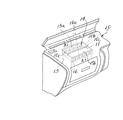
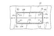
従来の自動車用エアーバッグ装置は、図1及び図2に示すような破断開放部の脆弱部となる破断溝を見えにくくしたシームレスタイプの助手席用エアーバッグ装置が提供されている。
即ち、図1及び図2において、内装パネル10には、図示しないレーザ発生手段からパルス状に発生するレーザを、内装パネル10の裏面側からその裏面に固着する一対の金属製の板材料を折曲成形した補強板材11,11の外形縁部に沿って相対移動しながら照射することにより、内装パネル10の裏面に対して直角方向に形成された長尺方向の前,後ヒンジ溝10aと中央破断溝10b及び短尺方向の破断用溝10cを設けることで、エアーバッグ12を収容するエアーバッグケース13の開口部13aの大きさに対応するエアーバッグ膨張展開用の破断開放部14が形成されている。
また、前記破断開放部14は、長尺方向に形成した中央破断用溝10b,短尺の左右破断溝10c、10cによって、前,後破断開放部15a,15bとなりエアーバッグ膨張展開時に、それぞれ前記前,後ヒンジ溝10a,10aを介して観音開き状態に破断開口される構成になっている。
【0004】
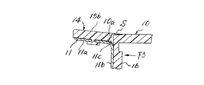
前記内装パネル10の破断開放部14は、エアーバッグ膨張展開時にエアーバッグ12の展開圧力により開放される際、前記前,後ヒンジ溝10aが前記内装パネル10より切り離されてしまう場合がある。そのため、前記内装パネル10の前記破断開放部14の裏面には、前記一対の補強板材11,11の一端水平部11a,11aが溶着等の手段によりカシメ固着され、その各他端となる鉛直部11b,11bが、ヒンジ部11c,11cを介して折り曲げられて垂下され、この各鉛直部11b,11bを、前記エアーバッグケース13の開口部13aの外周寸法より僅かに大きな内周寸法を有するようにして前記内装パネル10の裏面に一体成形された枠状の補強取付部16の前,後壁とともに、前記ケース13の前,後壁面13b,13bに取り付けられたフック部17に係止する構成とすることで、エアーバッグ膨張展開時に観音開きされた内装パネル10の破断開放部14が飛散しないようにしたものである。
なお、前記前,後破断開放部15a,15bの開放を阻害しないようにするため、前記一対の補強板材11,11の各他端の鉛直部11b,11bのフック係止用穴11d,11dは大きめに設定されており、前記前,後破断開放部15a,15bの開放と共に、前記各鉛直部11b,11bの上方への移動を可能にし、エアーバッグ膨張展開時の膨張圧力を吸収できるようにしている。
【0005】
上記のように構成された自動車用エアーバッグ装置においては、車両が衝突した際には、その衝突時の衝撃力をセンサで検出し、このセンサで検出した衝撃力が予め定めた値以上になった否かをCPU等からなる制御装置で判定し、設定値以上と判定された時に制御装置から出力される信号によりインフレータを動作させて所定のガスを発生させ、このガスをエアーバッグに供給することにより、エアーバッグを急速に膨張展開させる。
【0006】
すなわち、エアーバッグが膨張展開することにより、その圧力で、内装パネル10の破断開放部14が内側から押圧されると、破断開放部14の破断用溝10b,10cが破断され、前,後ヒンジ溝10aを介して観音開き状態に展開される。そして、観音開き状態に展開された前,後破断開放部15a,15bは各補強板材11,11のそれぞれのヒンジ部11c,11cを介して展開される。
これと同時に、エアーバッグ12は、開かれた破断開放部14から内装パネル10の外方へ膨張展開され、この膨張展開されたエアーバッグ12の緩衝作用で、助手席の乗員の頭部或いは胸部等を支えることにより、乗員を車両衝突時の衝撃力から保護するようにしている。
【0007】
【発明が解決しようとする課題】
ところで、上記の自動車用エアーバッグ装置においては、内装パネル10の破断開放部14が設けられている開口周縁の下方裏面には水平断面矩形状の補強取付部16が一体形成され、前,後側壁と左,右側壁とによってほぼ矩形筒状に形成されている。
【0008】
しかるに、図3の一点鎖線で示すように、エアーバッグ膨張展開時にはエアーバッグ12の急激な膨張圧力が、前記矩形筒状の前,後側壁16aに対し矢印F1方向に、また前記左,右側壁16bに対しては矢印F2方向に夫々作用する。
したがって、前記矩形筒状の補強取付部16の各角隅部16cは、矢印F3方向の内向きに変形反力が働く。この状態で破断開放部14が開放されるため、図4に示すように、前記各角隅部16cに対応する破断開放部16のコーナー破断部にササクレ現象Sが生じる不具合がある。
【0009】
また、エアーバッグ装置の作動時のエアーバッグ膨張初期に、補強取付部16の内側が外方に押されることで変形し、内装パネル10の破断開口部縁のコーナーに割れが発生したり、開口周縁が変形して内装パネル10の外観が損なわれるという問題もある。
【0010】
本発明は、上記のような従来の課題を解決するためになされたもので、本発明の目的は、前記エアーバッグケースを連結する補強枠体を備えた自動車用エアーバッグ装置において、前記補強枠体を前,後側壁と左,右側壁とによってほぼ矩形筒状に形成し、前記前,後側壁には前記エアーバッグケースを着脱可能に連結できるようにすると共に、矩形筒状の補強枠体の各角隅部には、エアーバッグの膨張展開時の膨張圧力による変形を少なくする変形防止手段を設け、破断開放部およびその開口周辺領域に与える展開圧力を吸収して、破断面にシャープなエッジが生じたり、破断部にささくれ現象が生じるのを予防し、奇麗な破断面とすることができる自動車用エアーバッグ装置を提供することにある。
【0011】
【課題を解決するための手段】
前記目的を達成するために本発明の請求項1に記載の発明は、自動車の室内に設けられた内装パネルの裏面側に配設され、インフレータからのガスにより膨張展開される前記エアーバッグを折り畳んだ状態で収納するエアーバッグケースと、前記エアーバッグケースの開口と相対向する前記内装パネルの裏面にエアーバッグ展開用の開口形状を決める破断用溝を形成することにより構成される破断開放部と、前記破断開放部及び前記破断開放部の開口周辺領域に対応する裏面を補強すると共に、前記エアーバッグケースを連結する補強枠体を備えた自動車用エアーバッグ装置において、前記補強枠体を前,後側壁と左,右側壁とによってほぼ矩形筒状に形成し、前記前,後側壁には前記エアーバッグケースを着脱可能に連結できるようにすると共に、矩形筒状の補強枠体の各角隅部には、エアーバッグの膨張展開時に発生するエアーバッグの膨張圧力による変形を少なくする変形防止手段を設けたことを特徴とする。
【0012】
請求項2の発明は、請求項1に記載した自動車用エアーバッグ装置において、前記補強枠体を前記エアーバッグケースを連結する係止部を備えた枠本体と、該枠本体の上部に一体成形された破断開放部用の破断補強部と前記破断開放部の開口周辺領域に対応する裏面を補強する縁補強部とで構成すると共に、前記枠本体の下部は、前,後側壁と左,右側壁とによって矩形筒状に形成し、かつ補強枠体の各角隅部にはエアーバッグの膨張展開時に発生するエアーバッグの膨張圧力による変形を少なくする変形防止手段を設け、前記枠本体の矩形筒状の上部周囲には、拡角方向にほぼ水平に延出する縁補強部を、また前記縁補強部の基部より連続する長手方向に波状の折曲部からなるヒンジ伸び代部を介して内方に分岐する破断補強部を形成し、前記枠本体と一体成形された破断補強部及び縁補強部を前記内装パネルの裏面に振動溶着によって固着するようにしたことを特徴とする。
【0013】
請求項3の発明は、請求項1に記載した自動車用エアーバッグ装置において、前記変形防止手段は、前,後側壁と左右側壁との交差する補強枠体の各角隅部に、各側壁が外方に突出しエアーバッグ膨張展開時の膨張圧力による変形を少なくするための湾曲部を設けたものであることを特徴とする。
【0014】
請求項4の発明は、請求項1に記載した自動車用エアーバッグ装置において、前記変形防止手段は、前記内装パネルの裏面と接合する前記補強枠体の各角隅部の接合部分を所望長さ切除した形状としたものであることを特徴とする。
【0015】
請求項5の発明は、請求項1〜4のいずれか1つに記載した自動車用エアーバッグ装置において、前記枠本体及び一体成形の前記補強枠体をオレフィン系エラストマーなどよりなる低弾性の熱可塑性樹脂材によって一体成形により形成したことを特徴とする。
【0016】
請求項6の発明は、請求項1〜4のいずれか1つに記載した自動車用エアーバッグ装置において、前記内装パネル裏面に対応する破断補強部及び縁補強部のそれぞれの対応面にはそれぞれ所定間隔をもって突設した筋条の突起部を形成し、これらの突起部を介して前記内装パネル裏面に振動溶着によって互いに固着するようにしたことを特徴とする。
【0017】
請求項7の発明は、請求項1〜4のいずれか1つに記載した自動車用エアーバッグ装置において、前記枠本体と一体成形された破断補強部及び縁補強部の前記内装パネルの裏面に対応する対応面には、所定間隔で形成した断裂筋状の振動溶着用の突起部を形成したことを特徴とする。
【0018】
【発明の実施の形態】
次に、本発明にかかる自動車用エアーバッグ装置の一実施形態について、図面を参照して説明する。
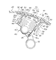
図5は本発明にかかる自動車用エアーバッグ装置を助手席用に適用した場合の要部縦断面図、図6は図5における補強枠体の全体斜視図、図7は図6の底面側から見た補強枠体の動作説明図である。
【0019】
図5において、40はポリプロピレン樹脂(PP)などの熱可塑性樹脂を主原料として一体成形された樹脂製のインストルメントパネルカバー(以下内装パネルという)であり、この内装パネル40は、図示省略の車体に固定された樹脂製のインストルメントパネルコアー(図示省略)の表面を覆うように構成され、タッピングネジ等の適宜の手段により、インストルメントパネルコアーに固定されている。
【0020】
前記内装パネル40の左側部分の助手席(右ハンドル車対応)と対向する内側箇所には、図5に示すように、自動車用エアーバッグ装置41が収容される収容部42が形成されている。なお、左ハンドル車対応の場合は前記構成と反対の右側部分に設けられる。
【0021】
前記自動車用エアーバッグ装置41は、インフレータからのガスにより膨張展開されるエアーバッグ43と、このエアーバッグ43を折り畳んだ状態で収容する上方に開口44aを有するエアーバッグケース44と、前記内装パネル40と同系の熱可塑性樹脂材料を使用して形成された補強枠体45を構成する枠本体46と、該枠本体46の上部に分岐して形成された一対の破断開放部用の破断補強部47a,47bと、破断開放部の開口周縁用の縁補強部48とからなる。
【0022】
前記枠本体46の下部は、前,後側壁46a,46bと左,右側壁46c,46dとによって矩形筒状に形成されると共に、前記枠本体46の矩形状の側壁上部には、拡角方向の傾斜面46eを介して四周面がほぼ水平となる前記縁補強部48が形成され、また前,後側壁46a,46bの上部にはそれぞれ前記縁補強部48の傾斜面46eの基部から分岐して波状に屈曲されたヒンジ伸び代部49を介して互いに内方に対応して連続形成された一対の破断補強部47a,47bが形成され、さらに前記矩形筒状の補強枠体45の各角隅部(コーナー部)は、エアーバッグの膨張展開時に発生するエアーバッグの膨張圧力による変形を少なくする変形防止手段60を設けてある。
【0023】
前記変形防止手段60は、前,後側壁46a,46bと左,右側壁46c,46dとの交差する各角隅部に各側壁46a,46c、46b,46dの連接部が外方に突出する湾曲部60aを夫々設けたものである。
【0024】
また、前記変形防止手段60の変形例として図8に示すように、前,後側壁46a,46bと左,右側壁46c,46dとの交差する補強枠体45の各角隅部46fの内装パネル40の裏面との接合部分を所望長さをカットした切欠部61を設けた構成としても、エアーバッグの膨張展開時に発生するエアーバッグの膨張圧力による変形を少なくすることが可能である。
【0025】
そして、前記枠本体46及び一体成形された縁補強部48及び破断補強部47a,47bはオレフィン系エラストマーなどよりなる低弾性の熱可塑性樹脂材によって射出成形により一体形成されたものである。
【0026】
また、前記内装パネル40の裏面と対応する前記縁補強部48及び破断補強部47a,47bの対応面にはそれぞれ所定間隔をもって突設した断裂筋条の突起部50が形成されており、これらの突起部50を介して前記内装パネル40裏面に振動溶着によって互いに固着するようになっている。
【0027】
また、前記収容部42と相対向する内装パネル40には、エアーバッグ43の膨張展開時にエアーバッグの押圧力により破断されて、開口する破断開放部51が形成されている。
【0028】
この破断開放部51は、内装パネル40裏面左右長手方向に沿って設けたヒンジ溝40a及び前後の短尺方向に沿って設けた側部破断用溝40cをエアーバッグケース44の開口44aとほぼ同一の長方形状にレーザ加工等により形成することにより構成されるものであり、破断開放部51の短尺方向すなわち側部破断用溝40cの中間には、破断開放部51の長尺方向の全長に亘り伸びる中央破断用溝40bがレーザ加工等により形成されており、エアーバッグ43の膨張展開時に破断開放部51が側部破断用溝40cと中央破断用溝40bの箇所から破断されることにより、ヒンジ溝40aにより構成されるヒンジ52,52を介して観音開き状態に展開される前,後の破断開放部51a,51bに分離されるようになっている。
【0029】
また、前記枠本体46の長手方向の前,後側壁46a,46bには複数の角穴状の係止部53が形成されており、前記エアーバッグケース44の前後側壁に取付けたフック部54が係止されるようになっている。
【0030】
本発明の実施形態においては、前記補強枠体45と破断補強部47a,47bとを一体形成により構成したので、エアーバッグ膨張展開時において、補強枠体45の各角隅部に作用する展開初期におけるエアーバッグの膨張圧力による変形を少なく抑制することで、破断開放部の変形を防止し、破断開放部51a,51bのスムーズな展開を図ると共に、破断部に生じるササクレ現象Sを解消できる。
【0031】
また、前記補強枠体45の下方には、エアーバッグ43を収納したエアーバッグケース44が配設され、ケース上端開口44aの側壁にはフック部54が設けられており、前記補強枠体45の係止部53に貫通係止されるようになっている。このエアーバッグケース44の下端にはエアーバッグ43にガスを供給するインフレータ(図示せず)が配設されている。
また、このエアーバッグケース44は支持部材55を介してクロスメンバー56など車体側の固定部材にボルトナット56aにより固定されるようになっている。
【0032】
以上のように構成された本発明の実施の形態による助手席用のエアーバッグ装置によれば、自動車などの車両が衝突した際には、その衝突時の衝撃力を図示省略した周知のセンサで検出し、このセンサで検出した衝撃力が予め定めた値以上になった否かを図示省略した周知のCPU等からなる制御装置で判定し、設定値以上と判定された時に制御装置から出力される信号により、図示省略した周知のインフレータを動作させて所定のガスを発生させ、このガスをエアーバッグ43に供給することにより、エアーバッグ43を急速に膨張展開させる。
【0033】
エアーバッグ43が膨張展開する場合、エアーバッグ43の膨張展開初期時に発生する圧力が破断補強部47a,47bの水平面と補強枠体45の内側にかかると、補強枠体45の各角隅部を変形させるような圧力が掛かるが、この膨張圧力を補強枠体45に設けた変形防止手段60により少なくできるため、破断面に生じやすいササクレ現象を防止できる。また、枠本体46と縁補強部48を開口側に拡がる傾斜で連結されているため、補強枠体45に対する膨張の影響が少なく,更に縁補強部48を内下方へ引っ張るようにするため内装パネル40の開口周縁の拡がりを少なくして割れを防止すると共に、この破断補強部47a,47bの水平面に溶着された破断開放部51a,51bは中央破断用溝40bの脆弱部分から側部の破断用溝40cの脆弱部分に沿い順次破断されると共に、この前,後の破断開放部51a,51bを含む破断補強部47a,47bの水平部は波状の折曲部を有するヒンジ伸び代部49を介して展開され、破断開放部51と破断補強部47a,47bとの溶着部分に掛かる無理な圧力抵抗を吸収することができる。
【0034】
展開最終段階では前記枠本体46の角穴状の係止部53のギャップによっても前記圧力を吸収できることで、内装パネル40の開口周縁に発生する損傷が防止でき、スムーズに観音開き状態に外側へ展開される。
【0035】
この実施の形態によれば、エアーバッグ膨張展開時の初期に補強枠体45の各角隅部(コーナー部)に掛かる変形圧力を変形防止手段により緩和すると共に、破断開放部51の前後,左右の四周囲の開口周辺領域は補強枠体45の縁補強部48に溶着されているため、破断開放部51の開放動作に追従することが抑制され破断用溝46cで速やかに破断されることになり、エアーバッグ43の膨張展開時に破断された破断開放部51a,51bの破断面にシャープなエッジが生じたり、破断部にささくれ現象が生じるのを予防し、奇麗な破断面を提供できる。
【0036】
さらに、破断開放部51の開口周辺領域は補強枠体45の縁補強部48により補強されているため、破断開放部51を含む内装パネル40の上方からの押圧力に対して耐圧性が増し、エアーバッグ装置の不使用時における内装パネル40の割れ,歪み等の変形を防止できる。
【0037】
また、この実施の形態によれば、内装パネル40と前記補強枠体45とを同系の熱可塑性樹脂材料で構成すると共に、内装パネル40に対応する前記補強枠体45の縁補強部48と破断補強部47a,47bの対応面には断裂筋条の突起部50を介して振動溶着するようにしたので、溶着部に熱による変形を生じさせることなく溶着作業が容易にできる。
【0038】
また、エアーバッグケース44は補強枠体45に対して分離可能に結合できる構成になっているため、廃車時などにエアーバッグケース44を補強枠体45から容易に取り外すことができ、産業廃棄物となるインフレータなどの関連部品を容易に分離除去でき、環境に悪影響を与えることが防止できる。
【0039】
なお、前記実施形態におけるヒンジ溝40a及び破断用溝40b,40cの形成は、内装パネル40の裏面側よりレーザ加工によって脆弱部を形成するようにしたが、これに限定されることなく、フライス溝加工又は型加工によっても形成出来ることは勿論であり、フライス溝加工による場合は、内装パネルの裏面側より切削して、内装パネルの表面側の肉厚を0.5mm〜0.8mmの範囲で残し量を設けるようにすると良い。その他、表面パネルの成形時に一体成形する等の方法がある。
【0040】
【発明の効果】
上記のように構成された自動車用エアーバッグ装置によれば、前記補強枠体を前,後側壁と左,右側壁とによってほぼ矩形筒状に形成し、前記前,後側壁には前記エアーバッグケースを着脱可能に連結できるようにすると共に、矩形筒状の前記補強枠体の各角隅部には、エアーバッグの膨張展開時に発生するエアーバッグの膨張圧力による変形を少なくする変形防止手段を設けた構成としたので、破断開放部およびその開口周辺領域に与える展開圧力を吸収して、破断面にシャープなエッジが生じたり、破断部にささくれ現象が生じるのを予防し、奇麗な破断面とすることができる自動車用エアーバッグ装置を提供することができる。
【0041】
また、リサイクル時において、従来のように金属製の枠体及び補強板材と樹脂製の内装パネルとを一々分離する作業を省略できる。
更にまた、エアバッグケースが補強枠体に対して分離可能に結合できる構成になっているため、廃車時などにエアーバッグを枠本体から容易に取り外すことができ、インフレータなどの関連部品を容易に分離除去でき、環境に悪影響を与えることが防止出来る効果を有する。
【0042】
【図面の簡単な説明】
【図1】従来の助手席用エアーバッグ装置の単板状の内装パネルにエアーバッグ膨張展開用の破断開放部を形成した状態を示す部分拡大説明図。
【図2】図2は図1のA−A線に沿う概略断面図。
【図3】図2の補強取付枠の底面を示す要部説明図。
【図4】図2の破断開放部のヒンジ部のササクレ現象の生じる状態を示す要部断面図。
【図5】本発明にかかる自動車用エアーバッグ装置を助手席用に適用した場合の実施形態を示す要部の縦断面図。
【図6】図5における補強枠体の全体斜視図。
【図7】本発明にかかる図6の補強枠体を底面側から見た動作説明図。
【図8】本発明にかかる補強枠体に形成した変形防止手段の変形例を示す要部斜視図。
【符号の説明】
40 内装パネル
40a ヒンジ溝
40b 中央破断用溝
40c 側部破断用溝
41 自動車用エアーバッグ装置
42 収容部
43 エアーバッグ
44 エアーバッグケース
45 補強枠体
46 枠本体
47a,47b 破断補強部
48 縁補強部
49 ヒンジ伸び代部
50 突起部
51 破断開放部
53 角穴状の係止部
54 フック部
60 変形防止手段
61 切欠部[0001]
TECHNICAL FIELD OF THE INVENTION
The present invention relates to a vehicle airbag device for protecting a passenger in a vehicle such as a passenger seat or a driver's seat from a frontal collision or a side collision in the event of a collision of a vehicle such as a vehicle, thereby ensuring passenger safety. In particular, the present invention relates to an improvement in a mounting structure of a reinforcing member at a break opening portion.
[0002]
[Prior art]
An airbag device applied to a vehicle such as an automobile for a passenger seat, a driver's seat, and right and left pillars basically includes an airbag, an airbag case for accommodating the airbag in a folded state, An inflator for inflating and deploying the airbag is provided, and the airbag device is arranged inside a vehicle interior panel.
The interior panel of an automobile is generally composed of an instrument panel made of a plastic resin such as a polypropylene resin which covers the surface of a panel core integrally formed of a plastic resin material such as a polypropylene resin.
[0003]
2. Description of the Related Art Conventional airbag devices for automobiles are provided with a seamless type airbag device for a passenger seat in which a rupture groove, which is a fragile portion of a rupture opening portion, as shown in FIGS.
That is, in FIGS. 1 and 2, the
The break
[0004]
When the
In order to prevent the opening of the front and rear breaking
[0005]
In the vehicle airbag device configured as described above, when a vehicle collides, the impact force at the time of the collision is detected by a sensor, and the impact force detected by the sensor becomes equal to or greater than a predetermined value. Is determined by a control device including a CPU or the like, and when it is determined that the value is equal to or greater than a set value, a signal output from the control device is used to operate an inflator to generate a predetermined gas and supply the gas to an air bag. This causes the airbag to inflate and deploy rapidly.
[0006]
That is, when the airbag is inflated and deployed to press the
At the same time, the
[0007]
[Problems to be solved by the invention]
By the way, in the above airbag device for a vehicle, a reinforcing
[0008]
However, as shown by the dashed line in FIG. 3, when the airbag is inflated and deployed, the rapid inflation pressure of the
Therefore, a deformation reaction force acts on each
[0009]
In addition, in the initial stage of inflation of the airbag during operation of the airbag device, the inside of the reinforcing
[0010]
The present invention has been made in order to solve the conventional problems as described above, and an object of the present invention is to provide a vehicle airbag apparatus having a reinforcing frame for connecting the airbag case, The body is formed in a substantially rectangular cylindrical shape by front and rear side walls and left and right side walls, and the air bag case can be detachably connected to the front and rear side walls, and a rectangular cylindrical reinforcing frame is formed. In each corner of the airbag, a deformation preventing means for reducing deformation due to the inflation pressure at the time of inflation and deployment of the airbag is provided. An object of the present invention is to provide an airbag device for an automobile, which can prevent an edge from being generated or an overburden phenomenon at a broken portion and can have a clean broken surface.
[0011]
[Means for Solving the Problems]
In order to achieve the above object, the invention according to claim 1 of the present invention folds the air bag which is disposed on the back side of an interior panel provided in the interior of an automobile and is inflated and deployed by gas from an inflator. An airbag case to be housed in an open state, and a break opening portion formed by forming a break groove for determining an opening shape for airbag deployment on the back surface of the interior panel opposed to the opening of the airbag case. A reinforcing member for reinforcing the back surface corresponding to the opening area of the break opening portion and the opening peripheral region of the break opening portion, and a reinforcing frame connecting the air bag case; The rear side wall and the left and right side walls are formed in a substantially rectangular cylindrical shape, and the front and rear side walls can be detachably connected to the airbag case. Both, each corner portion of the rectangular tubular reinforcing frame, characterized in that a means for preventing deformation to reduce the deformation due to the inflation pressure of the air bag occurring during inflation and deployment of the air bag.
[0012]
According to a second aspect of the present invention, in the airbag device for an automobile according to the first aspect, a frame main body having a locking portion for connecting the reinforcing frame body to the airbag case, and integrally formed on an upper portion of the frame main body. And a reinforced portion for reinforcing the back surface corresponding to the opening peripheral area of the rupture opening portion, and a lower portion of the frame body includes front and rear side walls and left and right sides. A wall is formed in a rectangular cylindrical shape, and at each corner of the reinforcing frame, deformation preventing means for reducing deformation due to the inflation pressure of the airbag generated at the time of inflation and deployment of the airbag is provided, and the rectangular shape of the frame main body is provided. Around the cylindrical upper portion, an edge reinforcement portion extending substantially horizontally in the widening direction, and a hinge extension portion formed of a wavy bent portion in the longitudinal direction that is continuous from the base of the edge reinforcement portion. Forming a fracture reinforcing part that branches inward, Wherein the Kiwaku body and breaking the reinforcing portion is integrally formed and the edge reinforcement portion is so fixed by vibration welding to the rear surface of the interior panel.
[0013]
According to a third aspect of the present invention, in the airbag device for an automobile according to the first aspect, the deformation preventing means includes a side wall at each corner of a reinforcing frame intersecting the front and rear side walls and the left and right side walls. It is characterized in that it is provided with a curved portion projecting outward to reduce deformation due to inflation pressure during inflation and deployment of the airbag.
[0014]
According to a fourth aspect of the present invention, in the airbag device for an automobile according to the first aspect, the deformation preventing means sets a joint portion of each corner of the reinforcing frame to a desired length to be joined to a back surface of the interior panel. It is characterized in that it has a cut shape.
[0015]
According to a fifth aspect of the present invention, in the airbag device for an automobile according to any one of the first to fourth aspects, the frame main body and the integrally molded reinforcing frame are made of a low-elasticity thermoplastic made of an olefin-based elastomer or the like. It is characterized by being formed integrally with a resin material.
[0016]
According to a sixth aspect of the present invention, in the vehicle airbag device according to any one of the first to fourth aspects, a predetermined surface is provided on each corresponding surface of the break reinforcing portion and the edge reinforcing portion corresponding to the back surface of the interior panel. It is characterized in that streak projections projecting at intervals are formed, and are fixed to each other on the back surface of the interior panel by vibration welding via these projections.
[0017]
According to a seventh aspect of the present invention, in the airbag device for an automobile according to any one of the first to fourth aspects, the fracture reinforcing portion and the edge reinforcing portion integrally formed with the frame main body correspond to the back surface of the interior panel. The corresponding surface is characterized in that a tear streak-like vibration welding projection formed at a predetermined interval is formed.
[0018]
BEST MODE FOR CARRYING OUT THE INVENTION
Next, an embodiment of an automobile airbag device according to the present invention will be described with reference to the drawings.
FIG. 5 is a longitudinal sectional view of a main part when the automobile airbag device according to the present invention is applied to a passenger seat, FIG. 6 is an overall perspective view of a reinforcing frame body in FIG. 5, and FIG. 7 is a bottom view of FIG. It is operation | movement explanatory drawing of the reinforcement frame seen.
[0019]
In FIG. 5,
[0020]
As shown in FIG. 5, an
[0021]
The
[0022]
The lower portion of the frame
[0023]
The deformation preventing means 60 has a curved shape in which the connecting portions of the
[0024]
As a modified example of the deformation preventing means 60, as shown in FIG. 8, the interior panel of each corner 46f of the reinforcing
[0025]
The
[0026]
Also, on the corresponding surfaces of the
[0027]
In the
[0028]
The
[0029]
Further, a plurality of square hole-shaped
[0030]
In the embodiment of the present invention, since the reinforcing
[0031]
An
The
[0032]
According to the airbag device for the passenger seat according to the embodiment of the present invention configured as described above, when a vehicle such as an automobile collides, the impact force at the time of the collision is determined by a well-known sensor (not shown). It is determined by a control device including a well-known CPU or the like (not shown) whether or not the impact force detected by the sensor is equal to or greater than a predetermined value. By operating a well-known inflator (not shown) in response to a predetermined signal, a predetermined gas is generated, and this gas is supplied to the
[0033]
When the
[0034]
In the final stage of deployment, the pressure can be absorbed by the gap of the rectangular hole-shaped
[0035]
According to this embodiment, the deformation pressure applied to the corners (corners) of the reinforcing
[0036]
Furthermore, since the opening peripheral region of the break
[0037]
According to this embodiment, the
[0038]
Further, since the
[0039]
In the above embodiment, the
[0040]
【The invention's effect】
According to the airbag device for an automobile configured as described above, the reinforcing frame is formed in a substantially rectangular cylindrical shape by the front and rear side walls and the left and right side walls, and the airbag is formed on the front and rear side walls. In addition to enabling the case to be removably connected, a deformation preventing means for reducing deformation due to the inflation pressure of the airbag generated when the airbag is inflated and deployed is provided at each corner of the rectangular cylindrical reinforcing frame. With the structure provided, it absorbs the developing pressure applied to the open part of the fracture and the area around the opening, preventing sharp edges on the fractured surface and preventing the fractured part from being overwhelmed. It is possible to provide an airbag device for a vehicle that can be used as a vehicle.
[0041]
Further, at the time of recycling, it is possible to omit the work of separating the metal frame and the reinforcing plate material and the resin interior panel one by one as in the related art.
Furthermore, since the airbag case is configured to be separable from the reinforcing frame, the airbag can be easily removed from the frame body when the vehicle is scrapped, and related parts such as the inflator can be easily installed. It has the effect that it can be separated and removed, and can be prevented from adversely affecting the environment.
[0042]
[Brief description of the drawings]
FIG. 1 is a partially enlarged explanatory view showing a state in which a break open portion for inflating and deploying an airbag is formed in a single-plate-shaped interior panel of a conventional passenger airbag device.
FIG. 2 is a schematic sectional view taken along line AA of FIG. 1;
FIG. 3 is an essential part explanatory view showing a bottom surface of the reinforcing attachment frame of FIG. 2;
FIG. 4 is a cross-sectional view of a main part showing a state in which a sacrificial phenomenon occurs in a hinge portion of the break open part in FIG. 2;
FIG. 5 is a longitudinal sectional view of an essential part showing an embodiment in which the automobile airbag device according to the present invention is applied to a passenger seat.
FIG. 6 is an overall perspective view of a reinforcing frame body in FIG. 5;
7 is an operation explanatory view of the reinforcing frame body of FIG. 6 according to the present invention as viewed from the bottom surface side.
FIG. 8 is an essential part perspective view showing a modification of the deformation preventing means formed on the reinforcing frame according to the present invention.
[Explanation of symbols]
40
Claims (7)
前記補強枠体を前,後側壁と左,右側壁とによってほぼ矩形筒状に形成し、前記前,後側壁には前記エアーバッグケースを着脱可能に連結できるようにすると共に、前記矩形筒状の補強枠体の各角隅部には、エアーバッグの膨張展開時に発生するエアーバッグの膨張圧力による変形を少なくする変形防止手段を設けたことを特徴とする自動車用エアーバッグ装置。An airbag case that is disposed on the back side of an interior panel provided in the interior of the vehicle and stores the airbag that is inflated and deployed by gas from an inflator in a folded state; and an opening facing the airbag case. A break opening portion formed by forming a break groove for determining an opening shape for airbag deployment on the back surface of the interior panel, and a back surface corresponding to the break opening portion and the opening peripheral region of the break opening portion. In addition to reinforcing, in an airbag device for an automobile having a reinforcing frame for connecting the airbag case,
The reinforcing frame is formed in a substantially rectangular tube shape by front and rear side walls and left and right side walls, and the air bag case can be detachably connected to the front and rear side walls. An airbag device for an automobile, wherein a deformation preventing means for reducing deformation caused by the inflation pressure of the airbag generated when the airbag is inflated and deployed is provided at each corner of the reinforcing frame body.
Priority Applications (1)
| Application Number | Priority Date | Filing Date | Title |
|---|---|---|---|
| JP2003152941A JP4330379B2 (en) | 2003-05-29 | 2003-05-29 | Airbag device for automobile |
Applications Claiming Priority (1)
| Application Number | Priority Date | Filing Date | Title |
|---|---|---|---|
| JP2003152941A JP4330379B2 (en) | 2003-05-29 | 2003-05-29 | Airbag device for automobile |
Publications (2)
| Publication Number | Publication Date |
|---|---|
| JP2004352105A true JP2004352105A (en) | 2004-12-16 |
| JP4330379B2 JP4330379B2 (en) | 2009-09-16 |
Family
ID=34048038
Family Applications (1)
| Application Number | Title | Priority Date | Filing Date |
|---|---|---|---|
| JP2003152941A Expired - Lifetime JP4330379B2 (en) | 2003-05-29 | 2003-05-29 | Airbag device for automobile |
Country Status (1)
| Country | Link |
|---|---|
| JP (1) | JP4330379B2 (en) |
Cited By (1)
| Publication number | Priority date | Publication date | Assignee | Title |
|---|---|---|---|---|
| JP2007210449A (en) * | 2006-02-09 | 2007-08-23 | Toyota Motor Corp | Door structure for airbag |
Citations (11)
| Publication number | Priority date | Publication date | Assignee | Title |
|---|---|---|---|---|
| JPH0538994A (en) * | 1991-08-02 | 1993-02-19 | Tokai Rika Co Ltd | Air bag device |
| JPH07125598A (en) * | 1993-11-01 | 1995-05-16 | Kansei Corp | Air bag device of front passenger seat |
| JPH11151728A (en) * | 1997-11-21 | 1999-06-08 | Inoac Corporation:Kk | Structure of air bag door part and production of air bag door part |
| JP3047684B2 (en) * | 1993-07-15 | 2000-05-29 | 日産自動車株式会社 | Airbag device |
| JP2000280846A (en) * | 1999-04-01 | 2000-10-10 | Daido Kasei Kogyo Kk | Casing cover for housing air bag |
| JP2001039252A (en) * | 1999-07-27 | 2001-02-13 | Toyo Tire & Rubber Co Ltd | Air bag device |
| JP2001294114A (en) * | 2000-04-17 | 2001-10-23 | Honda Motor Co Ltd | Instrument panel with air bag |
| JP2002012116A (en) * | 2000-06-29 | 2002-01-15 | Mitsuboshi Belting Ltd | Instrument panel integrated with air bag door and method of manufacture |
| JP2002046565A (en) * | 2000-07-18 | 2002-02-12 | Faurecia Industrie | Automobile accessories and corresponding assembly for air bag and manufacturing method thereof |
| JP2002144999A (en) * | 2000-11-15 | 2002-05-22 | Inoac Corp | Tearing structure of air bag door |
| JP2002211343A (en) * | 2001-01-17 | 2002-07-31 | Nishikawa Kasei Co Ltd | Interior member for vehicle with air bag door |
-
2003
- 2003-05-29 JP JP2003152941A patent/JP4330379B2/en not_active Expired - Lifetime
Patent Citations (11)
| Publication number | Priority date | Publication date | Assignee | Title |
|---|---|---|---|---|
| JPH0538994A (en) * | 1991-08-02 | 1993-02-19 | Tokai Rika Co Ltd | Air bag device |
| JP3047684B2 (en) * | 1993-07-15 | 2000-05-29 | 日産自動車株式会社 | Airbag device |
| JPH07125598A (en) * | 1993-11-01 | 1995-05-16 | Kansei Corp | Air bag device of front passenger seat |
| JPH11151728A (en) * | 1997-11-21 | 1999-06-08 | Inoac Corporation:Kk | Structure of air bag door part and production of air bag door part |
| JP2000280846A (en) * | 1999-04-01 | 2000-10-10 | Daido Kasei Kogyo Kk | Casing cover for housing air bag |
| JP2001039252A (en) * | 1999-07-27 | 2001-02-13 | Toyo Tire & Rubber Co Ltd | Air bag device |
| JP2001294114A (en) * | 2000-04-17 | 2001-10-23 | Honda Motor Co Ltd | Instrument panel with air bag |
| JP2002012116A (en) * | 2000-06-29 | 2002-01-15 | Mitsuboshi Belting Ltd | Instrument panel integrated with air bag door and method of manufacture |
| JP2002046565A (en) * | 2000-07-18 | 2002-02-12 | Faurecia Industrie | Automobile accessories and corresponding assembly for air bag and manufacturing method thereof |
| JP2002144999A (en) * | 2000-11-15 | 2002-05-22 | Inoac Corp | Tearing structure of air bag door |
| JP2002211343A (en) * | 2001-01-17 | 2002-07-31 | Nishikawa Kasei Co Ltd | Interior member for vehicle with air bag door |
Cited By (1)
| Publication number | Priority date | Publication date | Assignee | Title |
|---|---|---|---|---|
| JP2007210449A (en) * | 2006-02-09 | 2007-08-23 | Toyota Motor Corp | Door structure for airbag |
Also Published As
| Publication number | Publication date |
|---|---|
| JP4330379B2 (en) | 2009-09-16 |
Similar Documents
| Publication | Publication Date | Title |
|---|---|---|
| JP4285678B2 (en) | Airbag device for automobile | |
| JP2004001677A (en) | Air bag apparatus for automobile | |
| JP2002356136A (en) | Vehicular occupant crash protection device | |
| JP3923004B2 (en) | Cover body of airbag device | |
| JP2010159035A (en) | Cover body of airbag device and airbag device | |
| JP4762078B2 (en) | Air bag device and air bag cover | |
| JP5036652B2 (en) | Cover body of vehicle airbag device | |
| JP3694860B2 (en) | Airbag device for automobile | |
| JP4717532B2 (en) | Airbag device for automobile | |
| JP3950671B2 (en) | Fracture opening part structure of automobile air bag device | |
| JP2001206180A (en) | Air bag device for automobile | |
| JP2004352105A (en) | Air bag device for automobile | |
| JP4426814B2 (en) | Airbag device for automobile | |
| JP4426813B2 (en) | Airbag device for automobile | |
| JP2001277978A (en) | Structure of reinforcing plate in air bag device for automobile | |
| JP2004352104A (en) | Air bag device for automobile | |
| JP2004352106A (en) | Air bag device for automobile | |
| JP4426878B2 (en) | Airbag device for automobile | |
| JP4051250B2 (en) | Improved structure of break opening in automotive airbag device | |
| JP3889950B2 (en) | Airbag device for automobile | |
| JP4512249B2 (en) | Fracture opening reinforcing device in automobile airbag device | |
| JP3654347B2 (en) | Airbag device for automobile | |
| JP2005088634A (en) | Vehicle interior trim with airbag door part | |
| JP2005254893A (en) | Air bag device for automobile | |
| JP2005138674A (en) | Structure of rupture opening part in airbag device for automobile |
Legal Events
| Date | Code | Title | Description |
|---|---|---|---|
| A621 | Written request for application examination |
Free format text: JAPANESE INTERMEDIATE CODE: A621 Effective date: 20060519 |
|
| A977 | Report on retrieval |
Free format text: JAPANESE INTERMEDIATE CODE: A971007 Effective date: 20080530 |
|
| A131 | Notification of reasons for refusal |
Free format text: JAPANESE INTERMEDIATE CODE: A131 Effective date: 20080916 |
|
| A521 | Request for written amendment filed |
Free format text: JAPANESE INTERMEDIATE CODE: A523 Effective date: 20081114 |
|
| TRDD | Decision of grant or rejection written | ||
| A01 | Written decision to grant a patent or to grant a registration (utility model) |
Free format text: JAPANESE INTERMEDIATE CODE: A01 Effective date: 20090519 |
|
| A01 | Written decision to grant a patent or to grant a registration (utility model) |
Free format text: JAPANESE INTERMEDIATE CODE: A01 |
|
| A61 | First payment of annual fees (during grant procedure) |
Free format text: JAPANESE INTERMEDIATE CODE: A61 Effective date: 20090616 |
|
| R150 | Certificate of patent or registration of utility model |
Ref document number: 4330379 Country of ref document: JP Free format text: JAPANESE INTERMEDIATE CODE: R150 Free format text: JAPANESE INTERMEDIATE CODE: R150 |
|
| FPAY | Renewal fee payment (event date is renewal date of database) |
Free format text: PAYMENT UNTIL: 20120626 Year of fee payment: 3 |
|
| FPAY | Renewal fee payment (event date is renewal date of database) |
Free format text: PAYMENT UNTIL: 20130626 Year of fee payment: 4 |
|
| R250 | Receipt of annual fees |
Free format text: JAPANESE INTERMEDIATE CODE: R250 |
|
| R250 | Receipt of annual fees |
Free format text: JAPANESE INTERMEDIATE CODE: R250 |
|
| R250 | Receipt of annual fees |
Free format text: JAPANESE INTERMEDIATE CODE: R250 |
|
| R250 | Receipt of annual fees |
Free format text: JAPANESE INTERMEDIATE CODE: R250 |
|
| R250 | Receipt of annual fees |
Free format text: JAPANESE INTERMEDIATE CODE: R250 |
|
| R250 | Receipt of annual fees |
Free format text: JAPANESE INTERMEDIATE CODE: R250 |
|
| R250 | Receipt of annual fees |
Free format text: JAPANESE INTERMEDIATE CODE: R250 |
|
| R250 | Receipt of annual fees |
Free format text: JAPANESE INTERMEDIATE CODE: R250 |
|
| R250 | Receipt of annual fees |
Free format text: JAPANESE INTERMEDIATE CODE: R250 |
|
| R250 | Receipt of annual fees |
Free format text: JAPANESE INTERMEDIATE CODE: R250 |
|
| R250 | Receipt of annual fees |
Free format text: JAPANESE INTERMEDIATE CODE: R250 |
|
| EXPY | Cancellation because of completion of term |