JP2004348149A - Display - Google Patents
Display Download PDFInfo
- Publication number
- JP2004348149A JP2004348149A JP2004188443A JP2004188443A JP2004348149A JP 2004348149 A JP2004348149 A JP 2004348149A JP 2004188443 A JP2004188443 A JP 2004188443A JP 2004188443 A JP2004188443 A JP 2004188443A JP 2004348149 A JP2004348149 A JP 2004348149A
- Authority
- JP
- Japan
- Prior art keywords
- noise
- display
- image
- image data
- pseudo
- Prior art date
- Legal status (The legal status is an assumption and is not a legal conclusion. Google has not performed a legal analysis and makes no representation as to the accuracy of the status listed.)
- Granted
Links
- 230000000007 visual effect Effects 0.000 claims abstract description 15
- 238000000034 method Methods 0.000 abstract description 46
- 230000003068 static effect Effects 0.000 abstract description 15
- 238000010586 diagram Methods 0.000 description 14
- 238000013139 quantization Methods 0.000 description 11
- 238000007906 compression Methods 0.000 description 10
- 230000006835 compression Effects 0.000 description 9
- 238000013459 approach Methods 0.000 description 4
- 239000003086 colorant Substances 0.000 description 4
- 239000011159 matrix material Substances 0.000 description 4
- 238000003860 storage Methods 0.000 description 4
- 230000006978 adaptation Effects 0.000 description 3
- 230000005540 biological transmission Effects 0.000 description 3
- 238000004519 manufacturing process Methods 0.000 description 3
- 230000035945 sensitivity Effects 0.000 description 3
- 238000004364 calculation method Methods 0.000 description 2
- 238000005259 measurement Methods 0.000 description 2
- 238000011160 research Methods 0.000 description 2
- 238000001228 spectrum Methods 0.000 description 2
- 235000006810 Caesalpinia ciliata Nutrition 0.000 description 1
- 241000059739 Caesalpinia ciliata Species 0.000 description 1
- 241000023320 Luma <angiosperm> Species 0.000 description 1
- OAICVXFJPJFONN-UHFFFAOYSA-N Phosphorus Chemical compound [P] OAICVXFJPJFONN-UHFFFAOYSA-N 0.000 description 1
- 210000001175 cerebrospinal fluid Anatomy 0.000 description 1
- 230000000295 complement effect Effects 0.000 description 1
- 238000007796 conventional method Methods 0.000 description 1
- 238000012937 correction Methods 0.000 description 1
- 230000006837 decompression Effects 0.000 description 1
- 230000006866 deterioration Effects 0.000 description 1
- 238000009826 distribution Methods 0.000 description 1
- 230000008030 elimination Effects 0.000 description 1
- 238000003379 elimination reaction Methods 0.000 description 1
- 238000002474 experimental method Methods 0.000 description 1
- 239000000463 material Substances 0.000 description 1
- OSWPMRLSEDHDFF-UHFFFAOYSA-N methyl salicylate Chemical compound COC(=O)C1=CC=CC=C1O OSWPMRLSEDHDFF-UHFFFAOYSA-N 0.000 description 1
- RJMUSRYZPJIFPJ-UHFFFAOYSA-N niclosamide Chemical compound OC1=CC=C(Cl)C=C1C(=O)NC1=CC=C([N+]([O-])=O)C=C1Cl RJMUSRYZPJIFPJ-UHFFFAOYSA-N 0.000 description 1
- 238000005192 partition Methods 0.000 description 1
- 235000012736 patent blue V Nutrition 0.000 description 1
- 230000002123 temporal effect Effects 0.000 description 1
- 238000012360 testing method Methods 0.000 description 1
Images


Classifications
-
- H—ELECTRICITY
- H04—ELECTRIC COMMUNICATION TECHNIQUE
- H04N—PICTORIAL COMMUNICATION, e.g. TELEVISION
- H04N9/00—Details of colour television systems
- H04N9/64—Circuits for processing colour signals
-
- H—ELECTRICITY
- H04—ELECTRIC COMMUNICATION TECHNIQUE
- H04N—PICTORIAL COMMUNICATION, e.g. TELEVISION
- H04N1/00—Scanning, transmission or reproduction of documents or the like, e.g. facsimile transmission; Details thereof
- H04N1/46—Colour picture communication systems
- H04N1/56—Processing of colour picture signals
- H04N1/58—Edge or detail enhancement; Noise or error suppression, e.g. colour misregistration correction
-
- G—PHYSICS
- G06—COMPUTING; CALCULATING OR COUNTING
- G06T—IMAGE DATA PROCESSING OR GENERATION, IN GENERAL
- G06T5/00—Image enhancement or restoration
-
- G—PHYSICS
- G09—EDUCATION; CRYPTOGRAPHY; DISPLAY; ADVERTISING; SEALS
- G09G—ARRANGEMENTS OR CIRCUITS FOR CONTROL OF INDICATING DEVICES USING STATIC MEANS TO PRESENT VARIABLE INFORMATION
- G09G3/00—Control arrangements or circuits, of interest only in connection with visual indicators other than cathode-ray tubes
- G09G3/20—Control arrangements or circuits, of interest only in connection with visual indicators other than cathode-ray tubes for presentation of an assembly of a number of characters, e.g. a page, by composing the assembly by combination of individual elements arranged in a matrix no fixed position being assigned to or needed to be assigned to the individual characters or partial characters
- G09G3/2007—Display of intermediate tones
- G09G3/2044—Display of intermediate tones using dithering
- G09G3/2048—Display of intermediate tones using dithering with addition of random noise to an image signal or to a gradation threshold
-
- G—PHYSICS
- G09—EDUCATION; CRYPTOGRAPHY; DISPLAY; ADVERTISING; SEALS
- G09G—ARRANGEMENTS OR CIRCUITS FOR CONTROL OF INDICATING DEVICES USING STATIC MEANS TO PRESENT VARIABLE INFORMATION
- G09G5/00—Control arrangements or circuits for visual indicators common to cathode-ray tube indicators and other visual indicators
-
- H—ELECTRICITY
- H04—ELECTRIC COMMUNICATION TECHNIQUE
- H04N—PICTORIAL COMMUNICATION, e.g. TELEVISION
- H04N5/00—Details of television systems
- H04N5/14—Picture signal circuitry for video frequency region
- H04N5/21—Circuitry for suppressing or minimising disturbance, e.g. moiré or halo
-
- G—PHYSICS
- G06—COMPUTING; CALCULATING OR COUNTING
- G06T—IMAGE DATA PROCESSING OR GENERATION, IN GENERAL
- G06T2207/00—Indexing scheme for image analysis or image enhancement
- G06T2207/10—Image acquisition modality
- G06T2207/10024—Color image
-
- H—ELECTRICITY
- H04—ELECTRIC COMMUNICATION TECHNIQUE
- H04N—PICTORIAL COMMUNICATION, e.g. TELEVISION
- H04N19/00—Methods or arrangements for coding, decoding, compressing or decompressing digital video signals
- H04N19/90—Methods or arrangements for coding, decoding, compressing or decompressing digital video signals using coding techniques not provided for in groups H04N19/10-H04N19/85, e.g. fractals
Abstract
Description
本発明は、ディスプレイに関し、より詳細には、人間視覚システムのアスペクト比の利用及びディスプレイノイズの使用によってデジタルディスプレイのビット深さを拡張するディスプレイに関する。 The present invention relates to displays, and more particularly to displays that extend the bit depth of digital displays by utilizing the aspect ratio of the human visual system and using display noise.
連続階調画像、すなわちコントーン像は、通常最低で画素当たり24ビットを有している。通常のディスプレイでは、各色に8ビットを割り当てている。しかしながら、低コストのディスプレイは、画素当たりのビット数が制限されている。この制限は、ビデオランダムアクセスメモリ(VRAM)の制限された記憶容量、ディスプレイ自体の特性又は陰極線管(CRT)ディスプレイに使用されているディジタル/アナログ変換器(DAC)に起因する。 Continuous tone or contone images usually have a minimum of 24 bits per pixel. In a typical display, 8 bits are assigned to each color. However, low cost displays have a limited number of bits per pixel. This limitation is due to the limited storage capacity of the video random access memory (VRAM), the characteristics of the display itself, or the digital-to-analog converter (DAC) used in cathode ray tube (CRT) displays.
例えば、代表的なラップトップコンピュータの場合、最高の濃度(グレイレベル解像度で、通常“数千色”のモードである。このモードは1画素当たり16ビットに相当し、大型コンピュータ又はより多くのVRAMを有するコンピュータにおける画素当たり24ビットに匹敵する。この16ビットは通常、赤色に5ビット、緑色に6ビット、青色に5ビットを割り当てる。より低品質の製品の場合は、各色に5ビットを割り当てる15ビット/画素が用いられる。画素当たりのビット数をビット深さ(ビット深度ともいう)と呼ぶ。 For example, for a typical laptop computer, this is the highest density (gray level resolution, typically "thousands of colors" mode. This mode corresponds to 16 bits per pixel and is larger than a large computer or more VRAM. Equivalent to 24 bits per pixel in a computer with .16 bits, typically assigning 5 bits to red, 6 bits to green, and 5 bits to blue. For lower quality products, assign 5 bits to each color. 15 bits / pixel are used, and the number of bits per pixel is called bit depth (also called bit depth).
ビット深さが制限されているディスプレイの場合、円滑な階調領域に輪郭線の擬似信号が現れる。例えば、空の部分を含む画像は円滑な階調の空の青色領域に目に見える輪郭線を表示する。これらの擬似信号を除去させる従来技術は次の通りである。 In the case of a display having a limited bit depth, a pseudo signal of an outline appears in a smooth gradation area. For example, an image containing a sky portion displays a visible outline in the sky blue region of smooth gradation. The prior art for removing these pseudo signals is as follows.
L.G.Rovertsは、パルス符号変調方式(PCM)により符号化し伝送する画像の輪郭線の発生を防止する領域に関し、幾つかの独創的な論文を発表している。これは画像圧縮研究の最初であり、画像を7ビット/画素から2又は3ビット/画素に圧縮するために顕著な成果を収めた。この圧縮技法は、振幅の量子化による濃淡レベル(グレイレベル)解像度の低減を用いた。主要な歪みが擬似輪郭であり、それは緩やかに変化する階調における偽エッジとして報告された。 L. G. FIG. Roberts has published several original papers on areas that prevent the generation of contours in images transmitted by encoding using pulse code modulation (PCM). This was the first in image compression research and had significant results for compressing images from 7 bits / pixel to 2 or 3 bits / pixel. This compression technique used a reduction in gray level resolution by quantizing the amplitude. The main distortion was the false contour, which was reported as a false edge at a slowly changing tone.
図2に示した従来技術であるロバートの技法において、予定された1次元の白色雑音系列を量子化前のラスタ走査中の画像に加える。このノイズ系列は予定されているので、擬似ランダム雑音と呼ばれることも多い。画質の低下を避けるために、このノイズを受信後、ノイズが加えられた画像データが表示される前に除去する。差し引かれたノイズは、送信機のノイズと同相であり同一である。このノイズは、擬似輪郭を有効に除去する。 In the prior art Robert technique shown in FIG. 2, a predetermined one-dimensional white noise sequence is added to an image during raster scanning before quantization. Since this noise sequence is scheduled, it is often called pseudorandom noise. After receiving this noise, the image data to which the noise has been added is removed before the image data is displayed in order to avoid deterioration in image quality. The subtracted noise is in phase and identical to the transmitter noise. This noise effectively removes false contours.
この技法は、発表された時点において、この擬似輪郭の解消は実験的な観察に基づくものであった。しかしながら現在では、ノイズによって輪郭に沿った各要素の配向が変化し、視覚システムの連想フィールドの外に外れることが明らかにされている。量子化プロセスは画像中に若干のノイズを残すが、これは、ノイズの付加と除去のステップ間に発生したものである。 In this technique, at the time of its publication, the elimination of this false contour was based on experimental observations. However, it has now been shown that noise alters the orientation of each element along the contour and falls outside the associative field of the vision system. The quantization process leaves some noise in the image, which occurred between the steps of adding and removing noise.
上記の論文は、圧縮技法であったために、大半が無視されてきた。ディジタルパルス符号変調(DPCM)及び離散余弦変換(DCT)のより新しい技法により、擬似輪郭を発生させることなく大量の圧縮を可能とした。これらの技法は、主として圧縮プロセスを空間ドメインから周波数ドメインに移行させることにより実現する。 Most of the above papers have been ignored because they were compression techniques. Newer techniques of Digital Pulse Code Modulation (DPCM) and Discrete Cosine Transform (DCT) have enabled large amounts of compression without generating false contours. These techniques are implemented primarily by moving the compression process from the spatial domain to the frequency domain.
ロバートの方法の応用は、特許文献1と特許文献2に開示されている。1966年に発行された特許文献1は、図2に示した従来技術と類似のシステムを実装する。この特許において、ノイズの配分は均等であり、白色ノイズであると想定する。上記特許文献2におけるシステムは、ロバートの方法によるノイズを付加するが、受信機側ではノイズを除去しない。この付加ノイズは順序付けられたパターンを示す。 Applications of Robert's method are disclosed in US Pat. Patent document 1 issued in 1966 implements a system similar to the conventional technique shown in FIG. In this patent, it is assumed that the noise distribution is even and white noise. The system disclosed in Patent Document 2 adds noise by the Robert method, but does not remove the noise on the receiver side. This additional noise indicates an ordered pattern.
これらの技法は、通常、ハーフトーン技法において一般に使用されている用語ディザと区別するためにマイクロディザと呼ぶ。ハーフトーンディザは、空間ディザであるが、マイクロディザは振幅ディザである。表示装置と印刷装置のハーフトーンについてかなりの研究論文が発表されている。これらの資料は、一般に、ノイズを用いた一般的なディザ法と擬似輪郭の除去を目的としたディザ法の2つの範疇のいずれかに分類される。 These techniques are commonly referred to as microdither to distinguish them from the term dither commonly used in halftone techniques. Halftone dither is spatial dither, while micro dither is amplitude dither. Considerable research has been published on display and printing device halftones. These materials are generally classified into one of two categories: a general dither method using noise and a dither method for removing a false contour.
ディスプレイシステム用の一般的なディザ法は、1976年6月1日発行の特許文献3に記述されている。量子化画像をディザマトリックスと比較する。このディザマトリックスは、1度現れたグレイスケール値を全て含んでおり、従って、そのサイズは所望のグレイスケール解像度に依存する。
その他の例も、1992年11月17日発行の特許文献4に記述されているように、この制限を受ける。
A general dithering method for a display system is described in US Pat. Compare the quantized image with the dither matrix. This dither matrix contains all the grayscale values that have occurred once, and thus their size depends on the desired grayscale resolution.
Other examples are subject to this limitation, as described in US Pat.
その他のディザ法は、ディザ配列用の予定されたサイズを持っていない。1988年6月19日発行の特許文献5は、ディザ配列サイズを位相によって誘発させる。さらに、人間視覚システムの特性に関しても記述している。しかしながら、この記述は、ごく一般的なもので、本質的には、ディザリングパターンにおける空間及び時間的周波数が高いことを示しているだけである。 Other dithering methods do not have a predetermined size for dithering. U.S. Pat. No. 6,037,028 issued June 19, 1988 induces dither array size by phase. It also describes the characteristics of the human visual system. However, this description is very general and essentially only indicates that the spatial and temporal frequencies in the dithering pattern are high.
人間視覚システムの特性を利用することは、1997年4月8日発行の特許文献6に記述されている。使用されたノイズはハイパスノイズであるが、視覚システムの周波数感度に正比例するものとして使用される。その他のアプローチでは、ハイパスノイズ又はその近似値を使用する。例えば、1992年5月5日発行の特許文献7は、結果として得られるハーフトーンパターンが青色(ハイパス)ノイズに近似するようにディザ配列を設計することを提示している。 Utilizing the characteristics of the human visual system is described in US Pat. The noise used is high pass noise, but is used as being directly proportional to the frequency sensitivity of the vision system. Other approaches use high pass noise or an approximation thereof. For example, U.S. Pat. No. 6,037,028 issued May 5, 1992, states that the dither arrangement is designed such that the resulting halftone pattern approximates blue (high-pass) noise.
ディザのさらに一般的な定義が1990年9月11日発行の特許文献8に記述されている。この特許において、ディザリングは所望の色又はレベルに近い2つの色又は濃淡レベルのパターンを用いることであると定義されている。2つの色又はレベルは、目で平均化され、所望の色として現れる。ディザリングのために1ビットより多いビットを使用することをマルチビットディザリングと呼ぶ。 A more general definition of dither is described in US Pat. In this patent, dithering is defined as using a pattern of two colors or shade levels close to the desired color or level. The two colors or levels are visually averaged and appear as the desired color. Using more than one bit for dithering is called multi-bit dithering.
他のマルチビットディザリングは、各画素毎にディザ配列のサイズを制限する。例えば、1992年8月11日発行の特許文献9では、2×2画素当たりのディザ配列を使用している。他の技法では、所望の濃度数に基いてディザ配列のサイズを決定する。1997年12月9日発行の特許文献10は、256のレベルを生じる16×16のディザ配列サイズを記述している。 Other multi-bit dithering limits the size of the dither array for each pixel. For example, Patent Document 9 issued on August 11, 1992 uses a dither arrangement per 2 × 2 pixels. Other techniques determine the size of the dither array based on the desired number of concentrations. U.S. Pat. No. 6,074,837 issued Dec. 9, 1997 describes a 16 × 16 dither array size that yields 256 levels.
ディザリングは、上記のような一般的な場合と、特別な問題に対して用いられる。クリッピングとグレイスケールの誤差関数が問題であった場合に、マルチビットディザリングが適用された。これは、1993年4月6日発行の特許文献11に記述されている。 Dithering is used for the general case described above and for special problems. Multi-bit dithering was applied when clipping and gray scale error functions were a problem. This is described in US Pat.
上記のように、議論の対象である特別な擬似信号は擬似輪郭であり、緩かに変化する階調に現れる偽エッジである。ディザリングのようにノイズの付加を含む幾つかの技法が、この問題を解決するために用いられてきた。 As described above, the special pseudo signal under discussion is a pseudo contour, which is a false edge that appears in a slowly changing gradation. Several techniques, including the addition of noise, such as dithering, have been used to solve this problem.
1つのアプローチは、1993年6月8日発行の特許文献12に記述されているように、画像をエッジと非エッジの2つの領域に区分する。各セグメントは、異るフィルタで処理される。この方法の目的は、圧縮画像と伸張画像の後処理にあった。 One approach partitions the image into two regions, edge and non-edge, as described in US Pat. Each segment is processed with a different filter. The purpose of this method was to post-process the compressed and decompressed images.
他の技法は、特別な圧縮又は伸張技法を目的としている。例えば、1997年7月22日発行の特許文献13は、MPEG(動画像符号化標準)及びMPEG2スキームにおける擬似輪郭を対象としている。これらのスキームにおいて、輪郭は画像の暗い領域に発生する。この技法は、各々の領域に異なる利得を与え、撮影した画像のノイズを高めて擬似信号を解消する。
Other techniques are directed to special compression or decompression techniques. For example,
振幅量子化の擬似信号の特殊例である輪郭線が、1998年9月15日発行の特許文献14に記述されている。この技法は、実験を実施して量子化間隔を画像中に既に存在するノイズに基いて決定することを提案している。提案によれば、ノイズ/量子化の間隔は3/8とすべきである。
A contour line which is a special example of a pseudo signal for amplitude quantization is described in
最後に、印刷における擬似輪郭が、1999年7月6日発行の特許文献15に記述されている。2つのチャネルを使用し、1つのチャネル(レイヤ)で大きな点を作り、他のチャネルで小さな点を作る。
しかしながら、これらの方法は、いずれも、確実で簡単な計算方法では問題を解決できない。さらに、ディザリング技法は通常画像の空間解像度を低減させる。 However, none of these methods can solve the problem with a reliable and simple calculation method. Further, dithering techniques typically reduce the spatial resolution of an image.
本発明は、上述のごとき実情に鑑みてなされたものであり、計算が簡単であり画像の空間解像度を低減させない、擬似輪郭の除去又は低減方法を利用したディスプレイを提供することをその目的とする。 SUMMARY OF THE INVENTION The present invention has been made in view of the above circumstances, and has as its object to provide a display that uses a method of removing or reducing a false contour that is easy to calculate and does not reduce the spatial resolution of an image. .
第1の技術手段は、ビット深さが制限されているディスプレイにおいて、擬似ランダムノイズを連続階調画像データから減算してノイズ補償画像データに変換し、該ノイズ補償画像データを量子化して表示することにより、知覚ビットを拡張することを特徴としたものである。 The first technical means converts, in a display with a limited bit depth, pseudo-random noise from continuous tone image data to noise-compensated image data, and quantizes the noise-compensated image data for display. Thus, the perceptual bit is extended.
第2の技術手段は、第1の技術手段において、前記擬似ランダムノイズは、人間視覚システムノイズから成ることを特徴としたものである。 According to a second technical means, in the first technical means, the pseudorandom noise comprises human visual system noise.
第3の技術手段は、第1又は第2の技術手段において、前記知覚ビットは、画素あたり2または3ビット拡張されることを特徴としたものである。 According to a third technical means, in the first or the second technical means, the perceived bits are extended by 2 or 3 bits per pixel.
計算が簡単であり画像の空間解像度を低減させずに、擬似輪郭を除去或いは低減することができる。 The calculation is simple, and the pseudo contour can be removed or reduced without reducing the spatial resolution of the image.
本発明の1つの実施形態は、ディスプレイ装置の静的ノイズを利用してディスプレイ装置のビット深さを拡張する方法である。この方法は、ディスプレイ装置の静的ノイズを測定することと、それをコントーン(連続階調)画像データから差し引くことを含んでいる。ノイズ補償画像データを次に量子化して表示する。ディスプレイ装置の静的ノイズは、ノイズ補償画像データを元の連続階調画像データに変換する。ノイズの使用により、擬似輪郭が解消され、表示画像には目に見えるノイズは殆ど残らない。 One embodiment of the present invention is a method for extending the bit depth of a display device using static noise of the display device. The method involves measuring the static noise of the display device and subtracting it from the contone (continuous tone) image data. The noise compensated image data is then quantized and displayed. The static noise of the display device converts the noise compensated image data to the original continuous tone image data. The use of noise eliminates false contours and leaves little visible noise in the displayed image.
本発明の他の実施形態は、減算する静的ディスプレイノイズの代わりに人間視覚システム(HVS)に固有のノイズを用いるか又は擬似ランダムノイズを用いる方法である。さらなる実施形態では両方のタイプのノイズを使用する。HVSノイズを特にカラーディスプレイに使用するために、幾つかの異なる調整を実施することができる。 Another embodiment of the present invention is a method that uses noise inherent in the human visual system (HVS) or uses pseudo-random noise instead of subtracting static display noise. Further embodiments use both types of noise. Several different adjustments can be made to use HVS noise, especially for color displays.
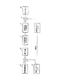
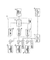
図1は本発明によるビット深さが制限されているディスプレイシステムの中の静的ディスプレイノイズを利用する一実施例を示す図、図2は伝送システムにロバートのノイズ変調を用いる従来技術例を示す図である。
図2で示す例の場合は画素当たり6ビットである連続階調(コントーン)画像10に、1次元の予定された白色ノイズ系列の擬似ランダムノイズ12を付加する。画像データを量子化器16にて量子化し、PCM符号化及び伝送ブロック11において符号化・伝送し、受信及びPCM復号ブロック13において受信・復号後に、減算器17においてこのノイズを減算する。量子化プロセスは、付加ステップと減算ステップ間量子化による若干の残差ノイズを画像に残す。
FIG. 1 is a diagram illustrating an embodiment using static display noise in a display system with a limited bit depth according to the present invention. FIG. 2 is a diagram illustrating a prior art example using Robert noise modulation in a transmission system. FIG.
In the case of the example shown in FIG. 2, a pseudo
使用した符号化スキームはパルス符号変調(PCM)であり、画素(ピクセル)当たりビット数を6から2に減少させた。この研究は、主として圧縮コンテキストに基いていたので、圧縮技法がその後より精錬されたことから主流から外れてしまった。DPCM及び離散余弦変換技術は、主として圧縮を空間ドメインから周波数ドメインに移行させることにより、擬似輪郭を発生させることなく圧縮度を向上させることができる。 The encoding scheme used was pulse code modulation (PCM), reducing the number of bits per pixel from six to two. Because this work was primarily based on the compression context, it has fallen out of the mainstream as compression techniques have become more refined since then. DPCM and discrete cosine transform techniques can improve the degree of compression without generating false contours, mainly by shifting the compression from the spatial domain to the frequency domain.
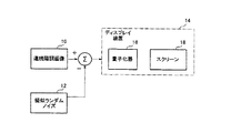
しかしながら、全体的なアイデアは、ビット深さが制限されたディスプレイに若干ではあるが応用されている。図3は、これらのディスプレイ装置に対するノイズ変調の適用実施例を示す図である。連続階調画像10に擬似ランダムノイズ12を結合し、ディスプレイ装置14に伝送する。結合データを量子化器16で量子化しスクリーン18に表示する。この発明の試験的な実験により、この技法は擬似輪郭の除去に有効であり、256のレベル(8ビット/画素)から64のレベル(6ビット/画素)に移行する際に特に有効であることが明らかにされた。しかしながら、ノイズを減算できないために、得られた画像は目に見えるノイズを有している。
However, the overall idea has been applied somewhat to displays with limited bit depth. FIG. 3 is a diagram showing an embodiment in which noise modulation is applied to these display devices. The
全体として、本発明の目的は、ビット深さに制限のあるディスプレイ装置の画質を改善することである。これは、偽輪郭(false contour)の発生を防止して、量子化よりも低いコントラストの信号を表示させることにより達成する。さらに、目に見えるノイズ(雑音)がディスプレイ装置に現れないようにして、これを実現する。この方法は、画素に関する簡単な付加操作と二次元ノイズ系列の記憶を用いる。別の方法では、二次元ノイズを保管するのではなくリアルタイムで発生させる。幾つかの実施形態においては、人間視覚システムのノイズを考慮に入れ、その考慮の元にそのノイズのパワースペクトルを形成する。 Overall, it is an object of the present invention to improve the image quality of display devices with limited bit depth. This is achieved by preventing the occurrence of false contours and displaying a signal with a lower contrast than the quantization. In addition, this is achieved by preventing visible noise from appearing on the display device. This method uses a simple addition operation on pixels and storage of a two-dimensional noise sequence. Another approach is to generate two-dimensional noise in real time rather than storing it. In some embodiments, the noise of the human visual system is taken into account, and the power spectrum of the noise is formed with that consideration.
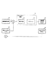
図1は本発明によるビット深さが制限されているディスプレイシステムの中の静的ディスプレイノイズを利用する一実施例を示す図である。ディスプレイ装置14は、固定パターン誤差20を測定し、静的ノイズを決定する。このノイズは、図2のコントラスト受信装置での減算ノイズとして扱われる。固定パターン誤差20を測定するステップから得たノイズ配列は、光単位からディジタルコード値に換算し、擬似ランダムノイズ12を発生させる。このノイズを量子化前に画像から減算し、ノイズ補償連続階調画像データを生成し、ディスプレイ装置の固有ノイズがこれを相殺する。この代わりに、連続階調画像にノイズの逆数を付加してもよい。両方共、他の技法と同様に、静的ディスプレイノイズを減算する技法と呼ぶ。量子化による小さな残差ノイズが存在するが、このディスプレイ装置は、上記ノイズ補償を略相殺する。
FIG. 1 is a diagram illustrating an embodiment using static display noise in a display system with a limited bit depth according to the present invention. The
本発明におけるディスプレイノイズは、静的なディスプレイノイズを意味することに留意すべきである。大多数の視聴者は、ディスプレイノイズを、実際には動的なノイズである画像中で連続して変化するノイズと結び付けるが、全てのディスプレイ装置は、装置に関連する静的なノイズを有している。例えば、代表的な陰極線管(CRT)ディスプレイは画像を形成するために用いられる蛍光体に関係するノイズを有している。 It should be noted that display noise in the present invention means static display noise. Most viewers associate display noise with continuously changing noise in the image, which is actually dynamic noise, but all display devices have static noise associated with the device. ing. For example, a typical cathode ray tube (CRT) display has noise associated with the phosphor used to form the image.
この測定は、製造される各ディスプレイ装置毎に製造時に実行できる。別の方法では、ディスプレイをモデル化して、ディスプレイの等級又はカテゴリ毎に固有のノイズを測定する。これは、図5に関する記述の際にも適用する。 This measurement can be performed during manufacture for each display device manufactured. In another method, the display is modeled to measure the unique noise for each display grade or category. This also applies to the description relating to FIG.
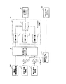
図4は、本発明によるビット深さが制限されているディスプレイシステムにおいて人間視覚システムのノイズを利用する一実施例を示す図である。ディスプレイノイズに加えて、人間視覚システム(HVS)の見解を含ませるような適応化も可能である。人間視覚システム22は、異なるモデル24を用いてモデル化することができる。その1例として、コントラスト感度関数(CSF)のモデルである簡単な二次元等方性ガウスローパスフィルタを挙げることができる。ディスプレイノイズ12とHVSノイズ24の結合を加算値として示している。しかしながら、その結合は、乗算、対数空間における加算、或いはガンマ補正空間における加算のような他の非線形結合であってもよい。
FIG. 4 is a diagram illustrating an example of using a noise of a human visual system in a display system with a limited bit depth according to the present invention. In addition to display noise, adaptations are also possible to include the views of the Human Visual System (HVS). The
画像に加えられたノイズのパワースペクトルは、周波数の関数としてのHVS輝度感度に反比例する。前述の米国特許第5,619,230号に記述されている方法と正反対である。再び、HVSノイズ又はディスプレイノイズであるノイズの減算ステップで、ノイズ補償画像データを生成する。HVSノイズは動的なノイズであり、従って、人間視覚システム(HVS)22では完全には消去できない。しかしながら、このノイズは少なくとも部分的に除去され、部分的にノイズ補償画像データを連続階調画像データに変換する。 The power spectrum of the noise added to the image is inversely proportional to the HVS luminance sensitivity as a function of frequency. This is exactly the opposite of the method described in the aforementioned US Pat. No. 5,619,230. Again, noise-compensated image data is generated in the step of subtracting noise that is HVS noise or display noise. HVS noise is dynamic noise and therefore cannot be completely eliminated by the human visual system (HVS) 22. However, this noise is at least partially removed, partially converting the noise compensated image data to continuous tone image data.
上述したように、図5は製造状況において生じ得る可能な実装例を示している。固有のディスプレイノイズが仮想HVSノイズに対して低い場合は、ディスプレイノイズを完全に無視することができ、HVSノイズのみを画像から減算する。これは、製造制約条件を考慮すれば最も実際的な方法であり、個々のディスプレイノイズの測定を必要としない。擬似ランダムノイズ12は、その後は、HVSのノイズモデル24から供給されるノイズのみから成る。
As mentioned above, FIG. 5 shows a possible implementation that can occur in a manufacturing situation. If the inherent display noise is low relative to the virtual HVS noise, the display noise can be completely ignored and only the HVS noise is subtracted from the image. This is the most practical method given the manufacturing constraints, and does not require individual display noise measurements. Thereafter, the pseudo
図1,図4,図5に示す本発明の実施例は、幾つかの点において、特にカラーディスプレイに適応可能である。この方法は、カラーディスプレイに直接適用できるが、特定ディスプレイ装置の特性と設計者の要望に合わせ若干の変更を加えることも可能である。 The embodiments of the invention shown in FIGS. 1, 4 and 5 are in some respects particularly adaptable to color displays. This method can be applied directly to a color display, but can be slightly modified to suit the characteristics of a particular display device and the needs of the designer.
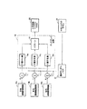
図6は、無彩色ノイズを用いるRGBカラーディスプレイへの本発明の応用を示す図である。同一ノイズフィールド12を連続階調画像の全3色平面10a−10cに加える。各色平面は、量子化器16a−cで個別に量子化して、ディスプレイスクリーン18に表示する。この技法の適応化として、輝度信号に対する逆貢献によるR,G及びBノイズフィールドのスケーリングがある。これは、HVSモデル24において生じる。しかしながら、これは、ディスプレイのグレースケールの非線性が補償されていない場合は、欠点となり得る。
FIG. 6 is a diagram showing an application of the present invention to an RGB color display using achromatic noise. The
図7は、より多くの記憶容量を要するが、ノイズの可視性が低く、輪郭線をより正確に防止することができる方法を示す図である。ここでは、HVSモデル24は、3つの異なる擬似ランダムノイズ平面12a−cを生成する有彩色モデルである。このモデルは、CIELAB色彩計のL*,A*及びB*チャネルと類似の視覚システムの輝度チャネルと2つの等輝度色チャネルの等価入力ノイズを含んでいる。さらに、これらの3チャネル用に各々異なる帯域幅と形状を有する異なるCSFを使用する。これは、3つの等価入力ノイズの擬似ランダム画像を生成するためである。これらを、次に、L*,A*,B*ドメインからRGBドメインに変換し、量子化前の画像に加える。
FIG. 7 is a diagram illustrating a method that requires more storage capacity but has low visibility of noise and can more accurately prevent contour lines. Here, the
この方法の主要な利点の1つは、ノイズが色層から色層まで独立しており、RGBの加重和により形成された輝度ノイズを、図6に示した実施形態の輝度ノイズより小さくできることである。もう1つの利点は、輝度CSFに関して低い帯域幅のCSFを有するためにノイズを等輝度R/G及びB/Y層の高周波数において特に高くできることである。これにより、全3層を同一レベルの輪郭除去に対する大きさを減少させることができる。 One of the major advantages of this method is that the noise is independent from color layer to color layer, and the luminance noise formed by the weighted sum of RGB can be smaller than the luminance noise of the embodiment shown in FIG. is there. Another advantage is that the noise can be particularly high at high frequencies of the isoluminous R / G and B / Y layers due to having a low bandwidth CSF with respect to the luminance CSF. As a result, the size of all three layers for removing the contour at the same level can be reduced.
図8は、図7のシステムの記憶容量問題を克服するために幾つかの効率的な手段を導入した本発明の実装例を示す。HVSの無彩色モデル24を使用して、単一ノイズフィールド12を発生させる。次に、このノイズフィールドを、各層毎に異なる量の空間オフセットを用いるカラー平面10a−cに付加する。これにより、3つの層を準独立とし、より低い振幅輝度信号を得る。このノイズは、ローパスではないので、自己相関距離は非常に短く、十分に独立した色ノイズを有する色平面を残す。
FIG. 8 illustrates an implementation of the present invention that introduces some efficient means to overcome the storage capacity problem of the system of FIG. A
画像が得られる形状により、図9に示すようなさらなる実施態様を適用できる。画像がCIELAB色成分空間で得られる場合は、例えば、ノイズをA*層(ここでは赤色/緑色等輝度画像10e)又はB*層(青色/黄色等輝度画像10f)又は両層に直接加えることができる。これらは、ほぼ、等輝度であるので、輝度信号は発生しない。HVSは輝度信号に最も敏感であるので、この方法は、最低のノイズ可視性をもつように輪郭線を分散させる。これは、ディスプレイの量子化器16a−cに先行するだけでなくRGBマトリックスブロック26に対する反対色にも先行して実施される。実装設計者は、RGBマトリックスの反対色でのクリッピングに注意しなければならない。この実装において、補色のノイズ合計は一定ではないが、無彩色成分であるR,G及びBの加重和は一定である。さらなる適応例においては、図8に示した空間オフセットをさらに適用できる。
Depending on the shape from which the image is obtained, further embodiments can be applied as shown in FIG. When the image is obtained in the CIELAB color component space, for example, noise is directly added to the A * layer (here, the red / green equal luminance image 10e) or the B * layer (the blue / yellow
カラーディスプレイに関し特に詳述した実施態様は、説明を容易にするために、HVSノイズに関してのみ記述されたことに留意すべきである。これらの実施形態は、図4の静的ディスプレイノイズ又は固定パターン誤差ノイズ20をさらに含んでいる。但し、本発明の適用をこのように限定するつもりはない。
It should be noted that the embodiments specifically described for color displays have been described only in terms of HVS noise for ease of explanation. These embodiments further include the static display noise or fixed
静的ディスプレイノイズ,HVSノイズ又は両ノイズを用いる全体的な手法を適用することにより、ビット深さが制限されているディスプレイのビット深さを有効に拡張することができる。実験結果は、知覚ビット深さが6ビット/画素から8又は9ビット/画素に増大できることを示している。 Applying static display noise, HVS noise, or an overall approach using both noises, can effectively extend the bit depth of a display with limited bit depth. Experimental results show that the perceived bit depth can be increased from 6 bits / pixel to 8 or 9 bits / pixel.
以上、ディスプレイのビット深さを拡張させる方法と構成に関する特定の実施形態について記述して来たが、かような特別な記述は、特許請求項の規定以外に本発明の範囲に制限を加えることを意図するものではない。 While a specific embodiment of a method and configuration for extending the bit depth of a display has been described, such specific description limits the scope of the invention other than as defined in the appended claims. It is not intended.
10…連続階調画像、10a…赤色連続階調画像、10b…青色連続階調画像、10c…緑色連続階調画像、10d…無彩色連続階調画像、10e…赤色/緑色等輝度画像、10f…青色/黄色等輝度画像、11…PCM符号化及び伝送ブロック、12…擬似ランダムノイズ、12a…擬似ランダムノイズ、12b…擬似ランダムノイズ、12c…擬似ランダムノイズ、13…受信及びPCM復号ブロック、14…ディスプレイ装置、16…量子化器、16a…赤色量子化器(R量子化器)、16b…青色量子化器(B量子化器)、16c…緑色量子化器(G量子化器)、17…減算器、18…スクリーン、20…固定パターン誤差、22…人間視覚システム(HVS)、24…HVSノイズのモデル、26…反対色からRGB画像へのマトリックス。 10 continuous tone image, 10a red continuous tone image, 10b blue continuous tone image, 10c green continuous tone image, 10d achromatic continuous tone image, 10e red / green equal brightness image, 10f ... blue / yellow equal luminance image, 11 ... PCM coding and transmission block, 12 ... pseudorandom noise, 12a ... pseudorandom noise, 12b ... pseudorandom noise, 12c ... pseudorandom noise, 13 ... reception and PCM decoding block, 14 ... Display device, 16 ... Quantizer, 16a ... Red quantizer (R quantizer), 16b ... Blue quantizer (B quantizer), 16c ... Green quantizer (G quantizer), 17 ... Subtractor, 18 ... Screen, 20 ... Fixed pattern error, 22 ... Human vision system (HVS), 24 ... Model of HVS noise, 26 ... Mato from opposite color to RGB image Box.
Claims (3)
擬似ランダムノイズを連続階調画像データから減算してノイズ補償画像データに変換し、
該ノイズ補償画像データを量子化して表示することにより、知覚ビットを拡張することを特徴とするディスプレイ。 For displays with limited bit depth,
Pseudo random noise is subtracted from the continuous tone image data and converted into noise compensated image data,
A display characterized by expanding perceived bits by quantizing and displaying the noise-compensated image data.
Applications Claiming Priority (1)
| Application Number | Priority Date | Filing Date | Title |
|---|---|---|---|
| US09/426,165 US6441867B1 (en) | 1999-10-22 | 1999-10-22 | Bit-depth extension of digital displays using noise |
Related Parent Applications (1)
| Application Number | Title | Priority Date | Filing Date |
|---|---|---|---|
| JP2003004690A Division JP3642777B2 (en) | 1999-10-22 | 2003-01-10 | Bit depth expansion method for display system |
Publications (2)
| Publication Number | Publication Date |
|---|---|
| JP2004348149A true JP2004348149A (en) | 2004-12-09 |
| JP3642783B2 JP3642783B2 (en) | 2005-04-27 |
Family
ID=23689614
Family Applications (6)
| Application Number | Title | Priority Date | Filing Date |
|---|---|---|---|
| JP2000319695A Pending JP2001175236A (en) | 1999-10-22 | 2000-10-19 | Bit depth expansion method of display system |
| JP2003004690A Expired - Fee Related JP3642777B2 (en) | 1999-10-22 | 2003-01-10 | Bit depth expansion method for display system |
| JP2004188443A Expired - Fee Related JP3642783B2 (en) | 1999-10-22 | 2004-06-25 | display |
| JP2005045350A Expired - Fee Related JP4587838B2 (en) | 1999-10-22 | 2005-02-22 | Display system |
| JP2005045355A Expired - Fee Related JP3933669B2 (en) | 1999-10-22 | 2005-02-22 | Image display method |
| JP2008010175A Expired - Fee Related JP4589412B2 (en) | 1999-10-22 | 2008-01-21 | Display system and bit depth expansion method |
Family Applications Before (2)
| Application Number | Title | Priority Date | Filing Date |
|---|---|---|---|
| JP2000319695A Pending JP2001175236A (en) | 1999-10-22 | 2000-10-19 | Bit depth expansion method of display system |
| JP2003004690A Expired - Fee Related JP3642777B2 (en) | 1999-10-22 | 2003-01-10 | Bit depth expansion method for display system |
Family Applications After (3)
| Application Number | Title | Priority Date | Filing Date |
|---|---|---|---|
| JP2005045350A Expired - Fee Related JP4587838B2 (en) | 1999-10-22 | 2005-02-22 | Display system |
| JP2005045355A Expired - Fee Related JP3933669B2 (en) | 1999-10-22 | 2005-02-22 | Image display method |
| JP2008010175A Expired - Fee Related JP4589412B2 (en) | 1999-10-22 | 2008-01-21 | Display system and bit depth expansion method |
Country Status (6)
| Country | Link |
|---|---|
| US (2) | US6441867B1 (en) |
| EP (5) | EP1094420B1 (en) |
| JP (6) | JP2001175236A (en) |
| KR (6) | KR100402666B1 (en) |
| DE (1) | DE60012653T2 (en) |
| TW (1) | TW508539B (en) |
Cited By (1)
| Publication number | Priority date | Publication date | Assignee | Title |
|---|---|---|---|---|
| JP2005107532A (en) * | 2003-09-30 | 2005-04-21 | Sharp Corp | Forming method and system of dither pattern array |
Families Citing this family (82)
| Publication number | Priority date | Publication date | Assignee | Title |
|---|---|---|---|---|
| US6441867B1 (en) * | 1999-10-22 | 2002-08-27 | Sharp Laboratories Of America, Incorporated | Bit-depth extension of digital displays using noise |
| US6535617B1 (en) * | 2000-02-14 | 2003-03-18 | Digimarc Corporation | Removal of fixed pattern noise and other fixed patterns from media signals |
| JP3763397B2 (en) * | 2000-03-24 | 2006-04-05 | シャープ株式会社 | Image processing apparatus, image display apparatus, personal computer, and image processing method |
| CN100401359C (en) | 2000-07-28 | 2008-07-09 | 克雷沃耶提公司 | Arrangement of color pixels for full color imaging devices with simplified addressing |
| US8022969B2 (en) * | 2001-05-09 | 2011-09-20 | Samsung Electronics Co., Ltd. | Rotatable display with sub-pixel rendering |
| US7274383B1 (en) * | 2000-07-28 | 2007-09-25 | Clairvoyante, Inc | Arrangement of color pixels for full color imaging devices with simplified addressing |
| US6950115B2 (en) * | 2001-05-09 | 2005-09-27 | Clairvoyante, Inc. | Color flat panel display sub-pixel arrangements and layouts |
| US7283142B2 (en) * | 2000-07-28 | 2007-10-16 | Clairvoyante, Inc. | Color display having horizontal sub-pixel arrangements and layouts |
| US7307646B2 (en) * | 2001-05-09 | 2007-12-11 | Clairvoyante, Inc | Color display pixel arrangements and addressing means |
| US7184066B2 (en) * | 2001-05-09 | 2007-02-27 | Clairvoyante, Inc | Methods and systems for sub-pixel rendering with adaptive filtering |
| US7221381B2 (en) | 2001-05-09 | 2007-05-22 | Clairvoyante, Inc | Methods and systems for sub-pixel rendering with gamma adjustment |
| US7123277B2 (en) | 2001-05-09 | 2006-10-17 | Clairvoyante, Inc. | Conversion of a sub-pixel format data to another sub-pixel data format |
| US20030117423A1 (en) * | 2001-12-14 | 2003-06-26 | Brown Elliott Candice Hellen | Color flat panel display sub-pixel arrangements and layouts with reduced blue luminance well visibility |
| WO2003053068A2 (en) | 2001-12-14 | 2003-06-26 | Clairvoyante Laboratories, Inc. | Improvements to color flat panel display sub-pixel arrangements and layouts with reduced visibility of a blue luminance well |
| US7492379B2 (en) | 2002-01-07 | 2009-02-17 | Samsung Electronics Co., Ltd. | Color flat panel display sub-pixel arrangements and layouts for sub-pixel rendering with increased modulation transfer function response |
| US7755652B2 (en) | 2002-01-07 | 2010-07-13 | Samsung Electronics Co., Ltd. | Color flat panel display sub-pixel rendering and driver configuration for sub-pixel arrangements with split sub-pixels |
| US7417648B2 (en) | 2002-01-07 | 2008-08-26 | Samsung Electronics Co. Ltd., | Color flat panel display sub-pixel arrangements and layouts for sub-pixel rendering with split blue sub-pixels |
| US20040051724A1 (en) * | 2002-09-13 | 2004-03-18 | Elliott Candice Hellen Brown | Four color arrangements of emitters for subpixel rendering |
| US7098927B2 (en) | 2002-02-01 | 2006-08-29 | Sharp Laboratories Of America, Inc | Methods and systems for adaptive dither structures |
| US7315277B2 (en) * | 2002-04-30 | 2008-01-01 | The Johns Hopkins University | Bit depth reduction for analog to digital conversion in global positioning system |
| US7245786B2 (en) * | 2002-05-10 | 2007-07-17 | 976076 Alberta Inc. | Filtering artifact from fMRI data using the stockwell transform |
| US20040080479A1 (en) * | 2002-10-22 | 2004-04-29 | Credelle Thomas Lioyd | Sub-pixel arrangements for striped displays and methods and systems for sub-pixel rendering same |
| KR100472483B1 (en) * | 2002-11-29 | 2005-03-10 | 삼성전자주식회사 | Method for reducing a false contour and apparatus therefor |
| US7046256B2 (en) | 2003-01-22 | 2006-05-16 | Clairvoyante, Inc | System and methods of subpixel rendering implemented on display panels |
| US6917368B2 (en) * | 2003-03-04 | 2005-07-12 | Clairvoyante, Inc. | Sub-pixel rendering system and method for improved display viewing angles |
| US7167186B2 (en) | 2003-03-04 | 2007-01-23 | Clairvoyante, Inc | Systems and methods for motion adaptive filtering |
| US20040196302A1 (en) | 2003-03-04 | 2004-10-07 | Im Moon Hwan | Systems and methods for temporal subpixel rendering of image data |
| KR100925195B1 (en) * | 2003-03-17 | 2009-11-06 | 엘지전자 주식회사 | Method and apparatus of processing image data in an interactive disk player |
| US7352374B2 (en) | 2003-04-07 | 2008-04-01 | Clairvoyante, Inc | Image data set with embedded pre-subpixel rendered image |
| US20040246280A1 (en) | 2003-06-06 | 2004-12-09 | Credelle Thomas Lloyd | Image degradation correction in novel liquid crystal displays |
| US7209105B2 (en) * | 2003-06-06 | 2007-04-24 | Clairvoyante, Inc | System and method for compensating for visual effects upon panels having fixed pattern noise with reduced quantization error |
| US7245783B2 (en) * | 2003-06-24 | 2007-07-17 | Eastman Kodak Company | System and method for estimating, synthesizing and matching noise in digital images and image sequences |
| US8243093B2 (en) | 2003-08-22 | 2012-08-14 | Sharp Laboratories Of America, Inc. | Systems and methods for dither structure creation and application for reducing the visibility of contouring artifacts in still and video images |
| EP1522963A1 (en) * | 2003-10-07 | 2005-04-13 | Deutsche Thomson-Brandt Gmbh | Method for processing video pictures for false contours and dithering noise compensation |
| US7440633B2 (en) * | 2003-12-19 | 2008-10-21 | Sharp Laboratories Of America, Inc. | Enhancing the quality of decoded quantized images |
| US7424166B2 (en) * | 2003-12-24 | 2008-09-09 | Sharp Laboratories Of America, Inc. | Enhancing the quality of decoded quantized images |
| US7424168B2 (en) * | 2003-12-24 | 2008-09-09 | Sharp Laboratories Of America, Inc. | Enhancing the quality of decoded quantized images |
| US7248268B2 (en) | 2004-04-09 | 2007-07-24 | Clairvoyante, Inc | Subpixel rendering filters for high brightness subpixel layouts |
| US20050250821A1 (en) * | 2004-04-16 | 2005-11-10 | Vincent Sewalt | Quaternary ammonium compounds in the treatment of water and as antimicrobial wash |
| US7590299B2 (en) * | 2004-06-10 | 2009-09-15 | Samsung Electronics Co., Ltd. | Increasing gamma accuracy in quantized systems |
| US7366354B2 (en) * | 2004-06-30 | 2008-04-29 | Xerox Corporation | 10-bit per pixel processing using 8-bit resources |
| US7474316B2 (en) * | 2004-08-17 | 2009-01-06 | Sharp Laboratories Of America, Inc. | Bit-depth extension of digital displays via the use of models of the impulse response of the visual system |
| US7593465B2 (en) * | 2004-09-27 | 2009-09-22 | Lsi Corporation | Method for video coding artifacts concealment |
| EP1694055B1 (en) | 2005-02-21 | 2017-11-01 | Harman Becker Automotive Systems GmbH | Method for improving the subjective impression of a digitized image displayed with a low amplitude resolution, and video apparatus for carrying out the method |
| KR100763178B1 (en) * | 2005-03-04 | 2007-10-04 | 삼성전자주식회사 | Method for color space scalable video coding and decoding, and apparatus for the same |
| US8351756B2 (en) * | 2005-11-29 | 2013-01-08 | Panasonic Corporation | Reproduction device |
| US8254717B2 (en) | 2006-04-21 | 2012-08-28 | Tp Vision Holding B.V. | Picture enhancement by utilizing quantization precision of regions |
| JP4982844B2 (en) * | 2006-05-31 | 2012-07-25 | 大学共同利用機関法人情報・システム研究機構 | Projection image correction system and projection image correction program |
| US7876341B2 (en) | 2006-08-28 | 2011-01-25 | Samsung Electronics Co., Ltd. | Subpixel layouts for high brightness displays and systems |
| US8018476B2 (en) | 2006-08-28 | 2011-09-13 | Samsung Electronics Co., Ltd. | Subpixel layouts for high brightness displays and systems |
| US8279232B2 (en) | 2007-06-15 | 2012-10-02 | Ricoh Co., Ltd. | Full framebuffer for electronic paper displays |
| US8355018B2 (en) * | 2007-06-15 | 2013-01-15 | Ricoh Co., Ltd. | Independent pixel waveforms for updating electronic paper displays |
| US8416197B2 (en) | 2007-06-15 | 2013-04-09 | Ricoh Co., Ltd | Pen tracking and low latency display updates on electronic paper displays |
| US8319766B2 (en) * | 2007-06-15 | 2012-11-27 | Ricoh Co., Ltd. | Spatially masked update for electronic paper displays |
| US8203547B2 (en) * | 2007-06-15 | 2012-06-19 | Ricoh Co. Ltd | Video playback on electronic paper displays |
| US8913000B2 (en) * | 2007-06-15 | 2014-12-16 | Ricoh Co., Ltd. | Video playback on electronic paper displays |
| JP5342125B2 (en) * | 2007-10-11 | 2013-11-13 | セミコンダクター・コンポーネンツ・インダストリーズ・リミテッド・ライアビリティ・カンパニー | Video signal processing apparatus for dithering video signals |
| US8204333B2 (en) * | 2007-10-15 | 2012-06-19 | Intel Corporation | Converting video and image signal bit depths |
| JP5206276B2 (en) * | 2008-02-01 | 2013-06-12 | ソニー株式会社 | Gradation conversion device, gradation conversion method, and program |
| EP2099014B1 (en) * | 2008-03-07 | 2014-06-18 | Barco NV | A method and device to enhance image quality in digital video processing systems using dithering |
| KR101035579B1 (en) * | 2008-09-05 | 2011-05-19 | 매그나칩 반도체 유한회사 | Method for dithering and apparatus for the same |
| EP2169941A1 (en) * | 2008-09-26 | 2010-03-31 | Sony Corporation | Gradation conversion device and gradation conversion method |
| US8237733B2 (en) | 2009-03-31 | 2012-08-07 | Ricoh Co., Ltd. | Page transition on electronic paper display |
| US8243851B2 (en) * | 2009-04-01 | 2012-08-14 | Ubidyne, Inc. | Radio system and a method for relaying radio signals |
| US8396416B2 (en) * | 2009-04-01 | 2013-03-12 | Ubidyne, Inc. | Radio system and a method for relaying radio signals |
| US9397396B2 (en) * | 2009-04-01 | 2016-07-19 | Kathrein-Werke Kg | Radio system and a method for relaying packetized radio signals |
| US8731005B2 (en) * | 2009-10-12 | 2014-05-20 | Kathrein-Werke Kg | Absolute timing and Tx power calibration of the Tx path in a distributed system |
| KR101103883B1 (en) * | 2009-12-24 | 2012-01-12 | 한전케이피에스 주식회사 | Maintenance Method and Apparaus for Liner Plates of Spent Fuel Pit in Nuclear Power Plant |
| US8774196B2 (en) | 2010-06-03 | 2014-07-08 | Kathrein-Werke Kg | Active antenna array and method for relaying radio signals with synchronous digital data interface |
| US8897580B2 (en) * | 2012-07-30 | 2014-11-25 | Apple Inc. | Error diffusion with color conversion and encoding |
| US9105226B2 (en) | 2013-01-20 | 2015-08-11 | Qualcomm Incorporated | Spatio-temporal error diffusion for imaging devices |
| TWI546798B (en) | 2013-04-29 | 2016-08-21 | 杜比實驗室特許公司 | Method to dither images using processor and computer-readable storage medium with the same |
| EP3069513B1 (en) * | 2013-11-12 | 2019-03-13 | Dolby Laboratories Licensing Corporation | Pre-dithering in high dynamic range video coding |
| US9842424B2 (en) * | 2014-02-10 | 2017-12-12 | Pixar | Volume rendering using adaptive buckets |
| DE102014002213B4 (en) | 2014-02-21 | 2016-01-14 | MHIW b.v. | Method and burner head for metal inert gas welding |
| GB2526067B (en) | 2014-05-01 | 2019-02-27 | Imagination Tech Ltd | Noise enhanced histograms |
| CN105718235B (en) * | 2016-03-22 | 2019-02-05 | 华为技术有限公司 | Processing method, device and the image display system that image is shown |
| JP6912869B2 (en) * | 2016-06-15 | 2021-08-04 | オリンパス株式会社 | Image processing device, image processing program, image processing method |
| CN107481278B (en) * | 2017-08-21 | 2019-06-28 | 北京大学深圳研究生院 | Image bit depth expansion method and device based on combination frame |
| CN107492364A (en) * | 2017-09-26 | 2017-12-19 | 上海斐讯数据通信技术有限公司 | A kind of method and system that screen color temp tone is adjusted by ambient noise |
| US10832613B2 (en) | 2018-03-07 | 2020-11-10 | At&T Intellectual Property I, L.P. | Image format conversion using luminance-adaptive dithering |
| CN110191340B (en) * | 2019-06-03 | 2021-05-14 | Oppo广东移动通信有限公司 | Video frame processing method, device, equipment and storage medium |
Citations (6)
| Publication number | Priority date | Publication date | Assignee | Title |
|---|---|---|---|---|
| JPH06133164A (en) * | 1992-10-20 | 1994-05-13 | Fuji Xerox Co Ltd | Picture signal processing method and it device |
| US5525984A (en) * | 1993-08-06 | 1996-06-11 | Adc Telecommunications, Inc. | Optimization of weighted signal-to-noise ratio for a digital video encoder |
| JPH0918723A (en) * | 1995-06-30 | 1997-01-17 | Dainippon Screen Mfg Co Ltd | Gradation number converter and its method |
| JPH0983796A (en) * | 1995-09-12 | 1997-03-28 | Toshiba Corp | Image processor |
| JPH09185707A (en) * | 1995-10-13 | 1997-07-15 | Texas Instr Inc <Ti> | Reduction of contour generation of low intensity and color moving by means of dither |
| JPH11146203A (en) * | 1997-11-13 | 1999-05-28 | Namco Ltd | Image processor and storage medium storing program about device |
Family Cites Families (38)
| Publication number | Priority date | Publication date | Assignee | Title |
|---|---|---|---|---|
| US3244808A (en) | 1962-01-12 | 1966-04-05 | Massachusetts Inst Technology | Pulse code modulation with few amplitude steps |
| GB1218015A (en) * | 1967-03-13 | 1971-01-06 | Nat Res Dev | Improvements in or relating to systems for transmitting television signals |
| US3739082A (en) | 1972-02-29 | 1973-06-12 | Us Army | Ordered dither system |
| US3961134A (en) | 1975-05-09 | 1976-06-01 | Bell Telephone Laboratories, Incorporated | Bi-level display system |
| US4275411A (en) | 1978-04-19 | 1981-06-23 | Bernard Lippel | Dither-quantized signalling for color television |
| US4568966A (en) * | 1978-04-19 | 1986-02-04 | Quanticon Inc. | Compatible color television with regenerable signals |
| US4268861A (en) * | 1978-09-18 | 1981-05-19 | Massachusetts Institute Of Technology | Image coding |
| US4758893A (en) | 1985-09-23 | 1988-07-19 | Quanticon Inc. | Cinematic dithering for television systems |
| US5175807A (en) * | 1986-12-04 | 1992-12-29 | Quantel Limited | Video signal processing with added probabilistic dither |
| JPS63155948A (en) * | 1986-12-19 | 1988-06-29 | Fuji Photo Film Co Ltd | Processing method for picture signal |
| US4956638A (en) | 1988-09-16 | 1990-09-11 | International Business Machines Corporation | Display using ordered dither |
| US5254982A (en) | 1989-01-13 | 1993-10-19 | International Business Machines Corporation | Error propagated image halftoning with time-varying phase shift |
| US5309526A (en) * | 1989-05-04 | 1994-05-03 | At&T Bell Laboratories | Image processing system |
| US5201030A (en) | 1989-09-28 | 1993-04-06 | Sun Microsystems, Inc. | Method and apparatus for dithering graphic images |
| US5164717A (en) | 1989-09-28 | 1992-11-17 | Sun Microsystems, Inc. | Method and apparatus for the dithering of antialiased vectors |
| US5138303A (en) | 1989-10-31 | 1992-08-11 | Microsoft Corporation | Method and apparatus for displaying color on a computer output device using dithering techniques |
| US5218649A (en) | 1990-05-04 | 1993-06-08 | U S West Advanced Technologies, Inc. | Image enhancement system |
| US5111310A (en) | 1990-12-04 | 1992-05-05 | Research Technologies Corporation, Inc. | Method and apparatus for halftone rendering of a gray scale image using a blue noise mask |
| CA2063879C (en) * | 1991-05-28 | 1998-05-05 | Albert D. Edgar | Positive feedback error diffusion signal processing |
| US5333260A (en) | 1992-10-15 | 1994-07-26 | Digital Equipment Corporation | Imaging system with multilevel dithering using bit shifter |
| US5535020A (en) * | 1992-10-15 | 1996-07-09 | Digital Equipment Corporation | Void and cluster apparatus and method for generating dither templates |
| JP3245635B2 (en) * | 1992-10-16 | 2002-01-15 | 株式会社日立製作所 | Standardization and analysis of software products |
| US5311180A (en) * | 1993-01-15 | 1994-05-10 | The United States Of America As Represented By The Secretary Of The Navy | Digital circuit for the introduction and later removal of dither from an analog signal |
| JP3381339B2 (en) * | 1993-10-25 | 2003-02-24 | 株式会社富士通ゼネラル | Error diffusion circuit for pseudo halftone display |
| EP0652671A3 (en) | 1993-11-05 | 1995-06-21 | Ibm | Mapping colour digital image. |
| JPH07160217A (en) * | 1993-12-10 | 1995-06-23 | Matsushita Electric Ind Co Ltd | System and device for displaying color gradation |
| US5649083A (en) * | 1994-04-15 | 1997-07-15 | Hewlett-Packard Company | System and method for dithering and quantizing image data to optimize visual quality of a color recovered image |
| US5651078A (en) | 1994-07-18 | 1997-07-22 | Thomson Consumer Electronics, Inc. | Method and apparatus for reducing contouring in video compression |
| US6147671A (en) | 1994-09-13 | 2000-11-14 | Intel Corporation | Temporally dissolved dithering |
| US5696602A (en) | 1995-08-31 | 1997-12-09 | Lexmark International, Inc. | Method for halftoning using stochastic dithering with minimum density variance |
| US5818405A (en) * | 1995-11-15 | 1998-10-06 | Cirrus Logic, Inc. | Method and apparatus for reducing flicker in shaded displays |
| JPH09200523A (en) * | 1996-01-19 | 1997-07-31 | Ricoh Co Ltd | Image processor |
| JPH09214767A (en) * | 1996-02-06 | 1997-08-15 | Fuji Xerox Co Ltd | Picture processor |
| US5809178A (en) | 1996-06-11 | 1998-09-15 | Apple Computer, Inc. | Elimination of visible quantizing artifacts in a digital image utilizing a critical noise/quantizing factor |
| US5920653A (en) | 1996-10-22 | 1999-07-06 | Hewlett-Packard Company | Multiple spatial channel printing |
| KR19990056559A (en) * | 1997-12-29 | 1999-07-15 | 윤종용 | Noise reduction method and device |
| JP2000287086A (en) * | 1999-03-31 | 2000-10-13 | Minolta Co Ltd | Image processor |
| US6441867B1 (en) * | 1999-10-22 | 2002-08-27 | Sharp Laboratories Of America, Incorporated | Bit-depth extension of digital displays using noise |
-
1999
- 1999-10-22 US US09/426,165 patent/US6441867B1/en not_active Expired - Lifetime
-
2000
- 2000-10-17 EP EP00122640A patent/EP1094420B1/en not_active Expired - Lifetime
- 2000-10-17 EP EP03002754A patent/EP1322113A1/en not_active Withdrawn
- 2000-10-17 DE DE60012653T patent/DE60012653T2/en not_active Expired - Lifetime
- 2000-10-17 EP EP05013492A patent/EP1583360A3/en not_active Withdrawn
- 2000-10-17 EP EP05013491A patent/EP1583359A3/en not_active Withdrawn
- 2000-10-17 EP EP05013490A patent/EP1583358A3/en not_active Withdrawn
- 2000-10-18 TW TW089121824A patent/TW508539B/en not_active IP Right Cessation
- 2000-10-19 JP JP2000319695A patent/JP2001175236A/en active Pending
- 2000-10-21 KR KR10-2000-0062156A patent/KR100402666B1/en not_active IP Right Cessation
-
2002
- 2002-02-01 US US10/062,387 patent/US7450181B2/en not_active Expired - Fee Related
-
2003
- 2003-01-10 JP JP2003004690A patent/JP3642777B2/en not_active Expired - Fee Related
- 2003-02-03 KR KR1020030006575A patent/KR20030026262A/en active Application Filing
-
2004
- 2004-06-25 JP JP2004188443A patent/JP3642783B2/en not_active Expired - Fee Related
- 2004-07-23 KR KR10-2004-0057554A patent/KR100528938B1/en not_active IP Right Cessation
-
2005
- 2005-02-03 KR KR1020050009956A patent/KR100586335B1/en not_active IP Right Cessation
- 2005-02-03 KR KR1020050009958A patent/KR100548841B1/en not_active IP Right Cessation
- 2005-02-03 KR KR1020050009959A patent/KR100571084B1/en not_active IP Right Cessation
- 2005-02-22 JP JP2005045350A patent/JP4587838B2/en not_active Expired - Fee Related
- 2005-02-22 JP JP2005045355A patent/JP3933669B2/en not_active Expired - Fee Related
-
2008
- 2008-01-21 JP JP2008010175A patent/JP4589412B2/en not_active Expired - Fee Related
Patent Citations (6)
| Publication number | Priority date | Publication date | Assignee | Title |
|---|---|---|---|---|
| JPH06133164A (en) * | 1992-10-20 | 1994-05-13 | Fuji Xerox Co Ltd | Picture signal processing method and it device |
| US5525984A (en) * | 1993-08-06 | 1996-06-11 | Adc Telecommunications, Inc. | Optimization of weighted signal-to-noise ratio for a digital video encoder |
| JPH0918723A (en) * | 1995-06-30 | 1997-01-17 | Dainippon Screen Mfg Co Ltd | Gradation number converter and its method |
| JPH0983796A (en) * | 1995-09-12 | 1997-03-28 | Toshiba Corp | Image processor |
| JPH09185707A (en) * | 1995-10-13 | 1997-07-15 | Texas Instr Inc <Ti> | Reduction of contour generation of low intensity and color moving by means of dither |
| JPH11146203A (en) * | 1997-11-13 | 1999-05-28 | Namco Ltd | Image processor and storage medium storing program about device |
Cited By (2)
| Publication number | Priority date | Publication date | Assignee | Title |
|---|---|---|---|---|
| JP2005107532A (en) * | 2003-09-30 | 2005-04-21 | Sharp Corp | Forming method and system of dither pattern array |
| JP4703152B2 (en) * | 2003-09-30 | 2011-06-15 | シャープ株式会社 | Dither pattern generation method and system |
Also Published As
Similar Documents
| Publication | Publication Date | Title |
|---|---|---|
| JP4589412B2 (en) | Display system and bit depth expansion method | |
| US7474316B2 (en) | Bit-depth extension of digital displays via the use of models of the impulse response of the visual system | |
| JP6181259B2 (en) | Adaptive reconstruction for hierarchical coding of enhanced dynamic range signals. | |
| Daly et al. | Decontouring: Prevention and removal of false contour artifacts | |
| KR100782818B1 (en) | Method and system for luminance preserving color conversion from YUV to RGB | |
| KR100657339B1 (en) | Methods and system for combining luminance preserving quantization and halftoning | |
| Daly et al. | Bit-depth extension using spatiotemporal microdither based on models of the equivalent input noise of the visual system | |
| JP4420607B2 (en) | Image processing method and image processing apparatus | |
| US11277543B1 (en) | Perceptual dithering for HDR video and images | |
| KR0155799B1 (en) | Color-control device using masking function |
Legal Events
| Date | Code | Title | Description |
|---|---|---|---|
| A131 | Notification of reasons for refusal |
Free format text: JAPANESE INTERMEDIATE CODE: A131 Effective date: 20040921 |
|
| A521 | Request for written amendment filed |
Free format text: JAPANESE INTERMEDIATE CODE: A523 Effective date: 20041118 |
|
| TRDD | Decision of grant or rejection written | ||
| A01 | Written decision to grant a patent or to grant a registration (utility model) |
Free format text: JAPANESE INTERMEDIATE CODE: A01 Effective date: 20050125 |
|
| A61 | First payment of annual fees (during grant procedure) |
Free format text: JAPANESE INTERMEDIATE CODE: A61 Effective date: 20050125 |
|
| R150 | Certificate of patent or registration of utility model |
Free format text: JAPANESE INTERMEDIATE CODE: R150 |
|
| FPAY | Renewal fee payment (event date is renewal date of database) |
Free format text: PAYMENT UNTIL: 20080204 Year of fee payment: 3 |
|
| FPAY | Renewal fee payment (event date is renewal date of database) |
Free format text: PAYMENT UNTIL: 20090204 Year of fee payment: 4 |
|
| FPAY | Renewal fee payment (event date is renewal date of database) |
Free format text: PAYMENT UNTIL: 20100204 Year of fee payment: 5 |
|
| FPAY | Renewal fee payment (event date is renewal date of database) |
Free format text: PAYMENT UNTIL: 20100204 Year of fee payment: 5 |
|
| FPAY | Renewal fee payment (event date is renewal date of database) |
Free format text: PAYMENT UNTIL: 20110204 Year of fee payment: 6 |
|
| FPAY | Renewal fee payment (event date is renewal date of database) |
Free format text: PAYMENT UNTIL: 20120204 Year of fee payment: 7 |
|
| FPAY | Renewal fee payment (event date is renewal date of database) |
Free format text: PAYMENT UNTIL: 20120204 Year of fee payment: 7 |
|
| FPAY | Renewal fee payment (event date is renewal date of database) |
Free format text: PAYMENT UNTIL: 20130204 Year of fee payment: 8 |
|
| FPAY | Renewal fee payment (event date is renewal date of database) |
Free format text: PAYMENT UNTIL: 20130204 Year of fee payment: 8 |
|
| FPAY | Renewal fee payment (event date is renewal date of database) |
Free format text: PAYMENT UNTIL: 20140204 Year of fee payment: 9 |
|
| LAPS | Cancellation because of no payment of annual fees |