JP2004341474A - Method for manufacturing optical component, material for optical component, and optical component - Google Patents
Method for manufacturing optical component, material for optical component, and optical component Download PDFInfo
- Publication number
- JP2004341474A JP2004341474A JP2003349600A JP2003349600A JP2004341474A JP 2004341474 A JP2004341474 A JP 2004341474A JP 2003349600 A JP2003349600 A JP 2003349600A JP 2003349600 A JP2003349600 A JP 2003349600A JP 2004341474 A JP2004341474 A JP 2004341474A
- Authority
- JP
- Japan
- Prior art keywords
- lens
- lens array
- molding
- mold
- optical function
- Prior art date
- Legal status (The legal status is an assumption and is not a legal conclusion. Google has not performed a legal analysis and makes no representation as to the accuracy of the status listed.)
- Pending
Links
Images


Abstract
Description
本発明は、光学部品の製造方法、この製造方法に用いられる素材、あるいは、この製造方法によって製造された光学部品に関する。ここで、光学部品とは、例えばレンズ部品あるいはレンズアレイである。 The present invention relates to a method for manufacturing an optical component, a material used for the method, or an optical component manufactured by the method. Here, the optical component is, for example, a lens component or a lens array.
従来より、例えば2mm以下というような比較的小径のレンズの製造方法として、胴型で周囲への拡散を規制された1個の光学素材を上型と下型とで押圧してレンズを成型した後、上型を取り外し、出来上がったレンズを吸引具により取り出すレンズ製造方法が知られていた。 Conventionally, as a method of manufacturing a lens having a relatively small diameter of, for example, 2 mm or less, a lens is molded by pressing a single optical material whose diffusion to the surroundings is restricted by an upper mold and a lower mold with a barrel mold. Later, there has been known a lens manufacturing method in which the upper mold is removed and the completed lens is taken out by a suction tool.
しかし、この方法は、胴型の内径が例えば3mm以下というように極めて小型になると吸引具が適切に動作できなくなる不具合や、吸引できても胴型の外に取り出すことに困難を伴うなどの不具合があるためレンズを連設して一度に成形するレンズ製造方法が案出されるようになった。 However, this method is disadvantageous in that the suction tool cannot operate properly when the inside diameter of the body die is extremely small, for example, 3 mm or less, and it is difficult to take out the body out of the body die even if suction is possible. For this reason, a lens manufacturing method has been devised in which lenses are connected and molded at one time.
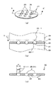
図11(a)はそのようにレンズを連設して一度に多数のレンズを成形するレンズ製造方法の一例を示す図であり、同図(b)は成形されて出来上がったレンズの集合体(レンズアレイ=lens array)を示す平面図である。このレンズ製造方法は、同図(a)に示すように、胴型1に周囲を規制され、下型2の上に載置された平板状の光学素材3を、上型4で押圧して、複数のレンズ5を一度に成形する。
FIG. 11A is a diagram showing an example of a lens manufacturing method in which a large number of lenses are formed at a time by arranging the lenses in a row, and FIG. It is a top view which shows a lens array (lens array). In this lens manufacturing method, as shown in FIG. 1A, a flat
図11(b)に示すように、このようにして出来あがった複数のレンズ5と、レンズ部を形成していない元の光学素材3とからなるレンズ集合体6は、全体のサイズが大きいので胴型内から容易に取り出すことができる。この後、レンズ5は個々に切り離されて個々に使用される。このレンズ製造方法は、一度に複数のレンズを成形できるので生産効率が向上する(例えば、特許文献1参照。)。
As shown in FIG. 11 (b), the
図12(a)〜(d)は、上記とやや方法は異なるが、一対の組み合わせレンズをそれぞれ個別に一度に複数個を成形して生産能率を上げる例を示す図である。同図(a)は、上下二枚の組み合わせレンズの上のレンズを一度に複数個成形する状態を示しており、胴型7と、この胴型7に一体な型面が平面の下型8と、これらで形成される型内に収容された光学素材9と、レンズ上型11とレンズ上型支持部材12とからなる上型13とを示している。そして、上型13が光学素材9を上から押圧して、レンズ上型11により上のレンズ14が成形された状態を示している。
FIGS. 12 (a) to 12 (d) are views showing an example in which a plurality of pairs of combined lenses are individually molded at a time to improve production efficiency, although the method is slightly different from the above. FIG. 3A shows a state in which a plurality of lenses on the upper and lower two combined lenses are formed at a time, and a
同図(b)は、上記のようにして出来上がった複数の上のレンズ14とレンズ部を形成していない元の光学素材9とからなるレンズ集合体15を示している。
同図(c)は、上下二枚の組み合わせレンズの下のレンズを一度に複数個成形する状態を示しており、胴型16と、この胴型16に一体なレンズ下型支持部材17とこのレンズ下型支持部材17に支持された複数のレンズ下型18とからなる下型19と、これらで形成される型内に収容された光学素材20と、型面が平面な上型21とを示している。そして、上型21が光学素材20を上から押圧して、レンズ下型18により下のレンズ22が成形された状態を示している。
FIG. 2B shows a
FIG. 3C shows a state in which a plurality of lenses below the upper and lower two combined lenses are molded at one time. The
同図(d)は、上記のようにして出来上がった複数の下のレンズ14とレンズ部を形成していない元の光学素材20とからなるレンズ集合体23を示している。上記の上のレンズ14と下のレンズ22が平面部によって個々に組み合わされて組み合わせレンズが形成される(例えば、特許文献2参照。)。
ところで、上記のレンズ集合体製造方法は、いずれもレンズ部と非レンズ部が同一の光学素材で形成されている。このとき、非レンズ部の厚さを薄くしようとすると、その全面を上下から押圧する押し型の成形負荷が大きくなり、このため押し型の寿命が短く、新たな押し型への交換頻度が高くなって経済的でないという問題があった。さらには、非レンズ部が割れるという問題も生じ、これらの問題の解決が望まれていた。 By the way, in each of the above-mentioned lens assembly manufacturing methods, the lens portion and the non-lens portion are formed of the same optical material. At this time, if the thickness of the non-lens portion is to be reduced, the forming load of the pressing die that presses the entire surface from above and below becomes large, so that the life of the pressing die is short, and the frequency of replacement with a new pressing die is high. There was a problem that it was not economical. Furthermore, there is also a problem that the non-lens portion is broken, and it has been desired to solve these problems.
また、レンズ集合から個々に切り出されるレンズは、光学機能面を形成する中央部分とその周囲の非光学機能部がガラスや樹脂等の同一の光学素材でできているため、物理的な歪みや光学的に不具合となるような癖が発生しやすい。そのような物理的な歪みや光学的に不具合となるような癖が抑制されて形状や精度等の品質の安定化したレンズの製造方法の出現が望まれていた。 In addition, in the lens individually cut out from the lens assembly, the central part forming the optical function surface and the non-optical function part around it are made of the same optical material such as glass and resin, so that physical distortion and optical It is easy to cause a habit that causes a malfunction. There has been a demand for a method of manufacturing a lens in which the physical distortion and the optically unusual habit are suppressed and the quality of the lens such as shape and accuracy is stabilized.
また、これらのレンズは、極めて小さなものであるため例えばCCD装置等への組み込みの際に精度よく組み込むための高度の技術が要求されるという問題を有していた。そして、例えば半田付けなどで精度よく容易に組み込む方法が模索されていた。
本発明の課題は、上記従来の実情に鑑み、押し型の寿命を長期化させ、成形されたレンズに物理的な歪みや光学的に不具合となるような癖がなく、且つ本体装置に精度よく容易に組み込むことができる光学部品の製造方法、あるいはそのための素材を提供することである。また、この製造方法により製造することにより、外周部の厚み(いわゆるコバ厚)の薄い光学部品であっても、取り扱いの容易な光学部品を提供することである。
In addition, since these lenses are extremely small, there is a problem that a high-level technology for accurately assembling them into, for example, a CCD device or the like is required. Then, a method of easily and accurately incorporating the components by, for example, soldering has been sought.
SUMMARY OF THE INVENTION In view of the above-mentioned conventional circumstances, an object of the present invention is to prolong the life of a press die, eliminate the habit of causing a molded lens to be physically distorted or optically defective, and provide a highly accurate main body device. An object of the present invention is to provide a method of manufacturing an optical component which can be easily incorporated, or a material therefor. Further, by manufacturing by this manufacturing method, it is possible to provide an optical component that can be easily handled even if the optical component has a small outer peripheral portion thickness (so-called edge thickness).
先ず、請求項1記載の発明のレンズアレイ製造方法は、レンズアレイの成形後において少なくとも光学機能面を含む面となる第1の素材と、レンズアレイの成形後において少なくとも光学機能面を含む面以外の面となる第2の素材と、を用いて成形して上記第1の素材と上記第2の素材とが一体化したレンズアレイを得るようにする。 First, the method for manufacturing a lens array according to the first aspect of the present invention is directed to a method for manufacturing a lens array other than a first material which is a surface including at least an optically functional surface after molding a lens array, And a second material, which is the surface of the first material, is molded to obtain a lens array in which the first material and the second material are integrated.
上記第1の素材と、上記第2の素材とは、例えば請求項2記載のように、同じ材質の素材であっても良い。
また、上記第2の素材は、例えば請求項3記載のように、遮光性の素材であっても良い。その場合、上記遮光性の素材は、例えば請求項4記載のように、金属、サーメット、又はセラミックスで構成することが好ましい。
The first material and the second material may be, for example, the same material.
Further, the second material may be a light-shielding material, for example. In this case, it is preferable that the light-shielding material is made of, for example, metal, cermet, or ceramic.
次に、請求項5記載の発明のレンズアレイ用素材は、レンズアレイの成形後において少なくとも光学機能面を含む面となる第1の素材と、レンズアレイの成形後において少なくとも光学機能面を含む面以外の面となる第2の素材と、を用いて成形して、上記第1の素材と上記第2の素材とが一体化したレンズアレイを得るレンズアレイ製造方法において用いられるレンズアレイ用素材であって、上記第2の素材は、上記第1の素材が嵌入する連設孔を備えて構成される。 Next, the material for a lens array according to the fifth aspect of the present invention includes a first material which is a surface including at least an optically functional surface after molding the lens array, and a surface including at least an optically functional surface after molding the lens array. A lens array material used in a lens array manufacturing method for obtaining a lens array in which the first material and the second material are integrated by molding using a second material that is a surface other than the first material. The second material has a continuous hole into which the first material fits.
上記連設孔は、例えば請求項6記載のように、レンズアレイ成形型の上下の押型のレンズ成形機能面の径よりも大きい径を備えて構成され、例えば請求項7記載のように、円筒形状に形成され、また、例えば請求項8記載のように、上下の開口部の径と内壁部の径が異なって形成され、また、例えば請求項9記載のように、内壁面が少なくともRa0.01ミクロン以上の粗さに形成される。
The connecting hole is configured to have a diameter larger than the diameter of the lens forming function surface of the upper and lower pressing dies of the lens array forming die, for example, as described in
また、上記第2の素材は、例えば請求項10記載のように、上下の押型内への収容時に上記上下の押型と位置決めするための位置決め部を備えており、この位置決め部は、例えば請求項11記載のように、少なくとも2箇所に設けられた貫通孔であり、また、例えば請求項12記載のように、少なくとも1箇所に設けられた周囲切り欠き部であるように構成される。
Further, the second material has a positioning portion for positioning the upper and lower press dies when the second material is accommodated in the upper and lower press dies, for example, as described in
次に、請求項13に記載の発明のレンズアレイは、レンズアレイの成形後において少なくとも光学機能面を含む面となる第1の素材と、レンズアレイの成形後において少なくとも光学機能面を含む面以外の面となる第2の素材と、を用いて成形して得られる、上記第1の素材と上記第2の素材とが一体化したレンズアレイであって、上記第2の素材は、上記第1の素材が嵌入する連設孔を備えて構成される。 Next, the lens array according to the thirteenth aspect of the present invention is a lens array other than a first material that becomes a surface including at least an optically functional surface after molding the lens array, and a surface that includes at least an optically functional surface after molding the lens array. A lens array obtained by molding using a second material to be the surface of the lens, wherein the first material and the second material are integrated, and the second material is It is provided with a continuous hole into which one material is fitted.
ここで、上記第1の素材と上記第2の素材とは、例えば請求項14記載のように、第1の素材が第2の素材に備えられている連設孔の内壁面に融着することによって一体化している。
ここで、上記連設孔は、例えば請求項15記載のように、レンズアレイ成形型の上下の押型のレンズ成形機能面の径よりも大きい径を備えている。
Here, the first material and the second material are, for example, as described in
Here, the continuous hole has a diameter larger than the diameter of the lens forming functional surfaces of the upper and lower pressing dies of the lens array forming die, for example.
ここで、例えば請求項16記載のように、上記第1の素材における上記第2の素材の内壁面との融着部分の厚みが0.3ミリメートル以下であるようにすることができる。
次に、請求項17記載の発明のレンズ部品の製造方法は、成形後において少なくとも光学機能面を含む面となる第1の素材と、成形後において少なくとも光学機能面を含む面以外の面となる第2の素材と、を用いて成形して、上記第1の素材と上記第2の素材とが一体化したレンズ部品を得るようにする。
Here, for example, the thickness of the portion of the first material fused to the inner wall surface of the second material may be 0.3 mm or less.
Next, in the method for manufacturing a lens component according to the seventeenth aspect of the present invention, the first material after molding has a surface including at least the optical function surface, and the molding has a surface other than the surface including at least the optical function surface By molding using the second material, a lens component in which the first material and the second material are integrated is obtained.
次に、請求項18記載の発明のレンズ素材は、成形後において少なくとも光学機能面を含む面となる第1の素材と、成形後において少なくとも光学機能面を含む面以外の面となる第2の素材と、を用いて成形して、上記第1の素材と上記第2の素材とが一体化したレンズ部品を得るレンズ部品の製造方法において用いられるレンズ素材であって、上記第2の素材は、上記第1の素材が嵌入する孔部を備えて構成される。
Next, the lens material of the invention according to
次に、請求項19記載の発明のレンズ素材は、成形後において少なくとも光学機能面を含む面となる第1の素材と、成形後において少なくとも光学機能面を含む面以外の面となる第2の素材と、を用いて成形して得られる、上記第1の素材と上記第2の素材とが一体化したレンズ部品であって、上記第2の素材は、上記第1の素材が嵌入する孔部を備えて構成される。 Next, the lens material according to the nineteenth aspect of the present invention is a lens material comprising a first material having at least an optical function surface after molding, and a second material having a surface other than at least the optical function surface after molding. A lens component obtained by molding using the material, wherein the first material and the second material are integrated, wherein the second material has a hole into which the first material is fitted. Unit.
以上のように、本発明によれば、上下の押し型の成形負荷を軽減でき、本体装置への組み付け時の半田付けを容易にでき、レンズに発生する歪み等の不具合を抑制でき、レンズ内における光学上の光の乱れを抑止でき、簡単な構成で精度よくレンズ素材と押型との位置決めができ、これにより小型レンズを量産する場合において形状精度等の品質の安定したレンズを成形することが可能となる。 As described above, according to the present invention, the molding load of the upper and lower pressing dies can be reduced, soldering at the time of assembling to the main body device can be facilitated, and problems such as distortion generated in the lens can be suppressed, and The optical disturbance in the optical system can be suppressed, and the lens material and the die can be accurately positioned with a simple configuration. This enables the production of lenses with stable quality such as shape accuracy when mass-producing small lenses. It becomes possible.
以下、本発明の実施の形態を図面を参照しながら説明する。
図1(a),(b),(c)は、一実施の形態におけるレンズアレイ製造方法を示す図である。先ず、同図(a)に示すように、このレンズアレイ製造方法は、レンズアレイ(上述の図11(b)に示した従来のレンズ集合体6と同様の形態のもの)の成形後において少なくとも光学機能面を含む面となる第1の素材25と、レンズアレイの成形後において少なくとも光学機能面を含む面以外の面となる第2の素材26とを用いて成形される。
Hereinafter, embodiments of the present invention will be described with reference to the drawings.
FIGS. 1A, 1B, and 1C are diagrams showing a lens array manufacturing method according to an embodiment. First, as shown in FIG. 11A, this method of manufacturing a lens array includes at least a lens array (having the same form as the
この第1の素材25は、第2の素材26に形成されている複数のレンズを連設するための連設孔27(同図に示す例では分かり易く9個として示している)の中に嵌入した状態で、第2の素材26と共に、同図(b)に示すように、レンズアレイ成形型の下押型28の上に載置される。なお、同図(b)は同図(a)のA−A′断面矢視図を示している。
The
この状態において、第1の素材25がガラス転移点より高く変形が可能な、適宜の高温下で、レンズアレイ成形型の上押型29が上方から、第2の素材26の面に接するまで同図(b)の矢印Bで示すように降下する。これにより、下押型28のレンズ成形機能面としてのレンズ下面型28−1と上押型29のレンズ成形機能面としてのレンズ上面型29−1によって第1の素材25が押圧され、レンズ下面型28−1とレンズ上面型29−1とに応じた形に成形され、全体として同図(c)に示すように、レンズアレイ30が成形される。このレンズアレイ30は、全体のサイズが大きいので、同図(b)の上押型29を除去した後で、型内から容易に取り出すことができる。
In this state, the
このレンズアレイ30は、同図(c)に示すように、レンズ機能部材である第1の素材25が、レンズ連設部材である第2の素材26の連設孔27に融着して第2の素材26と一体化しており、このように第2の素材26と一体化した第1の素材25から成るレンズ31が多数(この例では同図(a)に示すように9個)連設されている。
In the
このレンズ31の光学機能面(レンズとして有効に機能する面)31−1の寸法は、同図(c)に示すように、第2の素材26の連設孔27の有効径m(この有効径mについては詳しくは後述する)よりも小さく形成されている。このように、第1の素材25は、レンズアレイ30の成形後において、少なくとも光学機能面31−1を含む面を形成する。これに対して、第2の素材26は、少なくとも光学機能面31−1を含む面以外の面を形成することになる。この後、各レンズ31は個々に切り離される。
The dimension of the optically functional surface (the surface that effectively functions as a lens) 31-1 of the
以上のように、レンズ機能部材である第1の素材25をレンズ連設部材である第2の素材26の連設孔27の内壁部に融着させてレンズアレイ30を形成することにより、レンズ31の第2の素材26における連設孔27の内壁部との融着部分の厚み(図1(c)における光学機能面31−1の外周部分のレンズ31の厚み)を0.3mm以下の薄さでもいわゆるバリやカケを防止して形成することができる。
As described above, the
なお、同図には示していないが、各レンズ31を個々に切り離しやすいように、第2の素材26に連設孔27を形成する際に、切断用の格子状のスクライブラインを予め形成し、各格子内に連設孔27を形成するようにしてもよい。
また、図1(b),(c)では、上下のレンズ押型ともに、レンズを凸面に形成する型で示しているが、これに限ることなく、上下のレンズ押型は、いずれか一方がレンズ凸面用で他方がレンズ凹面用としても良く、また、上下ともレンズ凹面を形成する型としても良い。
Although not shown in the figure, when forming the
Also, in FIGS. 1B and 1C, both the upper and lower lens pressing molds are shown as molds in which the lens is formed as a convex surface. However, the present invention is not limited to this. The other may be for the concave surface of the lens, and the upper and lower sides may be of a type that forms the concave surface of the lens.
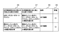
図2は、上記のレンズアレイ30の成形に用いられる第1の素材25と第2の素材26との組み合わせを示す図表である。同図に示す図表は、上述したように実用性のあるレンズアレイ30を成形するに至るまでに、本発明者によって行われた試行錯誤的試験において、種々試みられた第1の素材25と第2の素材26との組み合わせと、それぞれの組み合わせにおいて、それぞれ500回にわたって行われた成形後の第1の素材25と第2の素材26との融着状態を調べた結果を示している。
FIG. 2 is a chart showing a combination of the
同図の図表は、左から右へ、光学機能面を含む面以外の面となる第2の素材欄32、光学機能面を含む面となる第1の素材欄33、結果欄34、及び評価欄35から成る。そして、同図表の左端に示すように第1の素材25と第2の素材26の10種類の組み合わせによって成形試験を行った。
The chart in the figure includes, from left to right, a
第1の素材25と第2の素材26との組み合わせは、第2の素材欄32に示す石英ガラス(線膨張率5×10^−6)、ガラスA(線膨張率9×10^−6)、ガラスB(線膨張率10.4×10^−6)、ステンレス鋼(線膨張率16×10^−6)、及び炭素鋼(線膨張率12×10^−6)まで、1番目の第2の素材から6番目の第2の素材までに対して、第1の素材欄33に示すように、一律に上記のガラスA(線膨張率9×10^−6)を組み合わせている。
The combination of the first
そして、7番目の組み合わせとして、第2の素材としてTiCとTiNの混合材(線膨張率7.8×10^−6)、第1の素材としてガラスC(線膨張率11×10^−6)を用いている。また、8番目から10番目まで、第2の素材としてのWC(線膨張率6.4×10^−6)、SiC(線膨張率4.0×10^−6)、及びZrO2 (線膨張率9.5×10^−6)に対して、第1の素材として再びガラスAを組み合わせている。
As a seventh combination, a mixed material of TiC and TiN (linear expansion coefficient 7.8 × 10 × −6) as a second material, and glass C (
これらの組み合わせに対して、結果欄34に示すように、5番目の組み合わせを除いて、他の組み合わせでの成形では、図1(c)に示すように、第1の素材25と第2の素材26が500回の成形試験で全て融着していた。そして、5番目の組み合わせでは、500回の成形試験のうち、第1の素材25と第2の素材26との融着は80回の成形試験で認められ、残る420回の成形試験では融着は認められなかった。
With respect to these combinations, as shown in the
すなわち、評価欄35に示すように、5番目の組み合わせを除く他の組み合わせは全て評価が「○」であって合格であり、5番目の組み合わせのみ評価が「×」であって不合格となっている。これは、この不合格の5番目の組み合わせにおおける第2の素材である炭素鋼(線膨張率12×10^−6)が、炭素の含有率が高いことによりガラス素材と融着しにくいためと思われる。
That is, as shown in the
上記を総合すると、第1の素材25をガラスとした場合、第2の素材26は、第1の素材25と同様のガラス素材でも良く、また、ステンレスや銅のように金属でも良く、また、TiCとTiNの混合材あるいはWCのようにサーメット(cermet、ceramic metal の略)(金属の地に酸化物・炭化物・窒化物・硼化物・珪化物などを分散させた焼結複合材料)でも良く、また、SiCやZrO2 のようにセラミックス(ceramics、成形・焼成などの工程を経て得られる非金属無機材料の総称)であっても良いことが分かった。
To summarize the above, when the
そして、第2の素材26を金属とした場合、個々に切り離したレンズ31をCCD装置本体等に組み付けるとき、レンズ31を、その周囲の第2の素材26を介してCCD装置本体の金属筐体に容易に半田付けすることができ、これによってCCD装置本体へのレンズ31の組み付けが容易になり、組み立て工程における作業能率の向上に貢献するという利点が得られる。
When the
また、上記の金属、サーメット、又はセラミックスは、光非透過性(遮光性)の素材であるが、このような遮光性の素材を第2の素材26として用いた場合、レンズ31の周囲からのノイズ光が遮断されるので、レンズ31の光学機能が向上するという利点が得られる。
The above-mentioned metal, cermet, or ceramics is a light non-transmissive (light-shielding) material. When such a light-shielding material is used as the
なお、上記の例では第1の素材25として、種類の異なるものを含んではいるが全てガラス素材を用いている。しかし、上記第1の素材25としては、ガラス素材に限ることなく、レンズ機能を発揮できるものであれば樹脂素材を用いることもできる。
図3は、上述したレンズアレイ30の成形に用いられることが可能な樹脂素材からなる第1の素材25と第2の素材26との組み合わせを示す図表である。同図に示す図表も、実用性のあるレンズアレイ30を成形するに至るまでに、本発明者によって行われた試行錯誤的試験において、種々試みられた樹脂素材から成る第1の素材25と第2の素材26との組み合わせと、それぞれの組み合わせにおいて、それぞれ500回にわたって行われた成形後の第1の素材25と第2の素材26との融着状態を調べた結果を示している。
In the above example, although different types of materials are included as the
FIG. 3 is a table showing a combination of a
同図の図表も、左から右へ、光学機能面を含む面以外の面となる第2の素材欄36、光学機能面を含む面となる第1の素材欄37、結果欄38、及び評価欄39から成る。なお、図表は第1の素材25と第2の素材26の組み合わせを2行で示しているが、組み合わせが2種類という意味ではない。
Also in the table of FIG. 12, from left to right, a
例えば1行目の組み合わせで、第2の素材欄36には、ABS,ポリカーボネート、及びデルリンの3種類の樹脂が示され、第1の素材欄37には、環状オレフィン系ポリマー、ポリカーボネート、アクリル、及びスチレンメタクリル樹脂共重合体の4種類の樹脂が示されている。これは、これら3種類の樹脂と4種類の樹脂を適宜に選択して組み合わせて良いことを示している。つまり、この図表の1行目の各素材からは、第1の素材25と第2の素材26の組み合わせとして4×3=12種類の組み合わせが得られる。
For example, in the combination of the first row, the
また、同様に、2行目の組み合わせでは、第2の素材欄36には、環状オレフィン系ポリマー、ポリカーボネート、アクリル、及びスチレンメタクリル樹脂共重合体の4種類の樹脂が示され、第1の素材欄37には、上記同様に環状オレフィン系ポリマー、ポリカーボネート、アクリル、及びスチレンメタクリル樹脂共重合体の4種類の樹脂が示されている。これは、これら4種類の樹脂と4種類の樹脂を適宜に選択して組み合わせて良いことを示している。つまり、この図表の2行目の各素材からは、第1の素材25と第2の素材26の組み合わせとして4×4=16種類の組み合わせが得られる。
Similarly, in the combination of the second row, the
そして、いずれの場合も、結果欄38に示すように、1行目に示す12種類の組み合わせ、及び2行目に示す16種類の組み合わせの全ての組み合わせにおいて、第1の素材25と第2の素材26が良く融着するという結果が得られており、評価欄39に示すように、評価は「○」であって全て合格であった。
In any case, as shown in the
ところで、前述したように、第2の素材26は、その構成に、レンズ連設部材として、多数の連設孔27を備えている。この連設孔27の径と、レンズアレイ成形型の上下の押型のレンズ成形機能面としてのレンズ下面型28−1とレンズ上面型29−1の径との間には、特別の関係が設定されている。
By the way, as described above, the
図4は、その第2の素材26の連設孔27の径と、レンズアレイ成形型の上下の押型のレンズ成形機能面の径との関係を示す図である。同図に示すように、連設孔27の径mは、レンズアレイ成形型の上押型29のレンズ成形機能面としてのレンズ上面型29−1の径n1及び下押型28のレンズ成形機能面としてのレンズ下面型28−1の径n2よりも、大きく形成されている。
FIG. 4 is a diagram showing a relationship between the diameter of the
これにより、図1(c)に示すレンズアレイ30に形成されるレンズ31の光学機能面31−1は、常に第2の素材26の連設孔27の光学的有効サイズよりも小さく形成される。したがって、レンズ31の光学機能面31−1の光学機能が第2の素材26によって阻害されるという虞が全く無い。
Thereby, the optical function surface 31-1 of the
ところで、上述した例では、第2の素材26の連設孔27は、円筒状に形成されたものを示してきた。連設孔27がこのように円筒状であると、融着が十分でないと成形されたレンズ31が連設孔27から脱落するおそれがある。特に、第2の素材26が、ガラス素材以外の素材である場合に、連設孔27の内壁面が平滑であると、融着が十分に行われず、レンズ脱落の傾向が強くなることが試験による経験上から判明している。
By the way, in the above-described example, the
図5は、第2の素材26の連設孔27の内壁面の粗さと、第1の素材25の融着度との関係を示す図である。同図表は、左から右へ、連設孔の内壁面の粗さ欄41、成形試験の繰り返し回数欄42、結果欄43を示している。なお、成形試験の繰り返し回数欄42に示す成形試験の繰り返し回数は、いずれも500回である。
FIG. 5 is a diagram showing the relationship between the roughness of the inner wall surface of the
同図に示す連設孔の内壁面の粗さ欄41には、連設孔27の内壁面の粗さが、上から下へ、Ra0.005μm、Ra0.008μm、Ra0.01μm、及びRa0.015μmと、適宜の間隔で順次粗くなっていることを示している。このような粗さで内壁面が形成されている連設孔27に対して、特定の第1の素材25による融着試験をそれぞれ500回ずつ繰り返してみた結果が、結果欄43に示されている。
In the
結果欄43に示されるように、Ra0.005μmの粗さでは、500回の融着試験のうち融着しなかったものが420回、Ra0.008μmの粗さでは、160回、そして、Ra0.01μmの粗さでは、500回の融着試験で全てが融着し、更にRa0.015μmの粗さでは、同様に全てが融着するという結果が得られた。
As shown in the
すなわち、連設孔27の内壁面は、少なくともRa0.01ミクロン以上の粗さに形成されていることが望ましいことが判明した。
また、このような連設孔27の内壁面の粗さもさることながら、連設孔27の内壁面の形状も第1の素材25の融着のよしあしに関係する。
That is, it has been found that the inner wall surface of the
In addition to the roughness of the inner wall surface of the
図6(a)〜(e)は、連設孔27の内壁面の各種の形状を示す側断面図である。なお、図6(a)〜(e)に破線で示す丸形は、いずれも第1の素材25を示しており、第2の素材26が載置される下型の面が平面であると仮定したときの連設孔27(27a〜27e)と第1の素材25との位置関係を参考のために示したものである。
6A to 6E are side sectional views showing various shapes of the inner wall surface of the
図6(a)〜(e)において、同図(a)は、上述してきた円筒状の内壁面を有する連設孔27aを示しており、その内壁面は、少なくともRa0.01ミクロン以上の粗さに形成されている。
また、図6(b)〜(d)は、内壁面の粗さに関係なく、第1の素材25を良好に融着させることができる形状を示している。そして、同図(b)〜(d)では、連設孔27(27b〜27d)は、上下の開口部の径と内壁部の径が異なって形成されている。
6 (a) to 6 (e), FIG. 6 (a) shows the continuous hole 27a having the above-mentioned cylindrical inner wall surface, and the inner wall surface has a roughness of at least Ra 0.01 μm or more. Is formed.
6 (b) to 6 (d) show shapes that can satisfactorily fuse the
すなわち、同図(b)は、上下の開口部の径よりも内壁部の径のほうが大きく、連設孔27bの断面は、内壁部が角が形成されるように切り込まれている。また、同図(c)も、上下の開口部の径よりも内壁部の径のほうが大きい例であり、この場合は、連設孔27cの断面は、内壁部が円弧状に切り込まれている。
That is, in FIG. 3B, the diameter of the inner wall is larger than the diameter of the upper and lower openings, and the cross section of the
また、同図(d)は、上下の開口部の径よりも内壁部の径のほうが小さい例を示しており、連設孔27dの断面は、内壁部が角を形成して突出している。
同図(e)も、上下の開口部の径よりも内壁部の径のほうが小さい例を示しており、この例は、その内壁面に、粗い切り欠きでRa0.01ミクロン以上の段差を形成して、内壁面を更に粗面化した例を示している。上記の図6(b)〜(d)においても、内壁面をこのように粗面化して良いことは勿論である。
FIG. 3D shows an example in which the diameter of the inner wall is smaller than the diameter of the upper and lower openings, and the cross-section of the
FIG. 11E also shows an example in which the diameter of the inner wall is smaller than the diameter of the upper and lower openings. In this example, a step of Ra 0.01 μm or more is formed on the inner wall by a coarse notch. Then, an example in which the inner wall surface is further roughened is shown. 6B to 6D, the inner wall surface may of course be roughened as described above.
上記の図6(a)〜(e)に示す連設孔27(27a〜27e)の形状において、連設孔27aのように円筒状のもの及び連設孔27b、27cのように上下開口部の径よりも内壁部の径が大きい場合は、上下の開口部の径が、レンズに対する光学上の有効径となり、連設孔27d、27eのように上下開口部の径のほうが内壁部の径よりも大きい場合は、内壁部の径が、レンズに対する光学上の有効径となる。
In the shape of the continuous holes 27 (27a to 27e) shown in FIGS. 6 (a) to 6 (e), a cylindrical one like the continuous holes 27a and a vertical opening like the
ところで、上記のようにレンズ素材(第1の素材)やレンズ連設素材(第2の素材)を上下の押し型で成形するに際しては、レンズ素材が上下の押し型のレンズ上型面及びレンズ下型面に正確に位置対応していなければ正しいレンズが成形されない。一般に上下の押し型の相互位置は、図1では図示を省略した胴型によって位置決めされているから問題ないから、上下の押型内に収容されて下型に載置されるレンズ連設素材を下型に対して位置決めすれば、これによって結果的にレンズ素材が上下の押型と位置決めされる。 By the way, when the lens material (first material) and the lens continuous material (second material) are formed by the upper and lower pressing dies as described above, the lens material is formed by the upper and lower pressing dies and the lens. If the position does not correspond exactly to the lower mold surface, the correct lens cannot be formed. In general, since the mutual positions of the upper and lower pressing dies are determined by the body die (not shown in FIG. 1), there is no problem. Therefore, the lens continuous material accommodated in the upper and lower pressing dies and placed on the lower die is lowered. When the lens material is positioned with respect to the mold, the lens material is consequently positioned with the upper and lower pressing dies.
図7(a)は、下押型に対してレンズ連設素材(第2の素材)を位置決めするための構成例を下押型と対応付けて示す図であり、同図(b)は、その動作状態を示す図である。同図(a)に示すように、第2の素材26には連設孔27とは別に、少なくとも2箇所に、下押型28と位置決めするための位置決め用孔44が設けられている。
FIG. 7A is a diagram showing a configuration example for positioning the lens continuous material (second material) with respect to the down-pressing die in association with the down-pressing die, and FIG. It is a figure showing a state. As shown in FIG. 2A, a
これらの位置決め用孔44は、それぞれ下押型28に立設されている柱状の位置決め突起45に、同図(b)に示すように外嵌して位置決めされる。この位置決めにより、同図(a)に示す下押型28のレンズ下型面28−1に、第2の素材26の連設孔27が正しく対応する。そして、同図(b)に示すように、その連設孔27に嵌入されるレンズ素材(第1の素材)が、レンズ下型面28−1に正しく位置対応する。勿論、これによってレンズ素材(第1の素材)は、図7(b)には図示を省略しているが図1(b)に示した上押型29のレンズ上面型29−1にも正しく位置対応する。
These positioning holes 44 are externally fitted and positioned on
なお、上記の位置決め用孔44は、図7(a),(b)に示す例では貫通孔として形成されているが、下押型と位置決めすればよいのであるから貫通孔に限る必要はない。例えば第2の素材の下面に形成された凹部又は溝等であってもよく、その場合は、その凹部又は溝等に係合する凸部又は条形突部を下押型側に形成すればよい。
The
また、凹凸を逆にして、第2の素材の下面に突部を形成し、この突部と係合する凹部を下押型に形成するようにしても良い。これでも位置決めとしては同様の結果が得られる。
また、第2の素材に形成される位置決め部は、上記のように少なくとも2箇所に設けられる位置決め用の孔、凹部、溝、凸部、条突等に限るものではない。第2の素材の周囲の任意の1箇所を切り欠くことによっても位置決め部を形成することができる。
Alternatively, the projections may be formed on the lower surface of the second material with the concavities and convexities reversed, and the recesses engaged with the projections may be formed in a lower press die. Even with this, the same result can be obtained as positioning.
Further, the positioning portions formed on the second material are not limited to the positioning holes, concave portions, grooves, convex portions, protrusions, and the like provided in at least two places as described above. The positioning portion can also be formed by cutting out any one place around the second material.
図8は、下押型に対してレンズ連設素材(第2の素材)を位置決めするための他の構成例を下押型と対応付けて示す図である。同図に示すように、第2の素材26の周囲の一部には、円弧上の周囲を直線的に切り欠かれた切り欠き部26−1が形成されている。この第2の素材26の周囲の形状に即応した形状で、すなわち円弧状段差部28−2と、これに連続する直線状段差部28−3により下押型28の素材載置面が周囲から下方に段差をもって形成されている。
FIG. 8 is a diagram showing another configuration example for positioning the lens continuous material (second material) with respect to the lower press die in association with the lower press die. As shown in the figure, a part of the periphery of the second
この周囲から下方に段差をもって形成されている下押型28の素材載置面に第2の素材26が載置されるときは、第2の素材26の切り欠き部26−1が下押型28の直線状段差部28−3に一致するように載置される。これにより、第2の素材26が下押型28の素材載置面に対して位置決めされる。
When the
なお、上記の例では第2の素材26の切り欠き部26−1を直線状の切り欠き部としたが、これに限ることなく、角状の切り欠きでも良く、半円状の切り欠きでも良い。要は、第2の素材26の円形の周囲を、周囲の円弧以外の形状に切り欠いて、この切り欠き部に対応する段差部を、下押型側に備えるようにすればよい。
In the above example, the cutout portion 26-1 of the
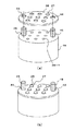
次に、図9に示す本発明の別の実施形態について説明する。本実施形態のレンズ部品は、結果として図1に示す製造方法によって得られたものに類似している。但し、本実施形態のレンズ部品は、レンズアレイを切断して得られたものではない。すなわち、これは、1つのレンズと1つの保持部材とを準備してこれらからレンズ部品を製造したものである。 Next, another embodiment of the present invention shown in FIG. 9 will be described. The lens component of the present embodiment is similar to that obtained by the manufacturing method shown in FIG. 1 as a result. However, the lens component of the present embodiment is not obtained by cutting the lens array. That is, this is one in which one lens and one holding member are prepared, and a lens component is manufactured therefrom.
レンズ部品50は第1の素材51と第2の素材52とからなる。第2の素材52は、その中央部に開口部を有している。そして、この開口部の内面で、第1の素材51と一体化されてレンズ部品50が形成されている。
このレンズ部品50の成形は図10に示すように行われる。すなわち、下押型53上に第2の素材52を配置し、その第2の素材52の開口部に第1の素材51を配置する。ここで、第1の素材52が変形可能となる温度まで加熱を行い、第1の素材51が軟化した時点で上押型54を降下させる。このようにして2つの成形型で上下から挟み込むことによってレンズ面を形成する。
The
The molding of the
このように、第1の素材51と第2の素材52を異ならせているので、例えば第2の素材52として吸着性の良い素材を用いればレンズ部品50の取り扱いが容易になる。あるいは、第2の素材52として鉄やニッケルなどの金属を用いれば、磁石等による磁力でレンズ部品50を保持できるので取り扱いが容易になる。
As described above, since the
その他、本発明は、上述した実施形態に限定されることなく、本発明の要旨を逸脱しない範囲内で種々の改良・変更が可能である。 In addition, the present invention is not limited to the above-described embodiment, and various improvements and modifications can be made without departing from the gist of the present invention.
1 胴型
2 下型
3 光学素材
4 上型
5 レンズ
6 レンズ集合体
7 胴型
8 下型
9 光学素材
11 レンズ上型
12 レンズ上型支持部材
13 上型
14 上のレンズ
15 レンズ集合体
16 胴型
17 レンズ下型支持部材
18 レンズ下型
19 下型
20 光学素材
21 上型
22 下のレンズ
23 レンズ集合体
25 第1の素材
26 第2の素材
26−1 周囲切り欠き部
27、27a〜27e 連設孔
29 上押型
29−1 レンズ上面型
28 下押型
28−1 レンズ下面型
28−2 円弧状段差部
28−3 直線状段差部
30 レンズアレイ
31 レンズ
31−1 光学機能面
32、36 第2の素材欄
33、37 第1の素材欄
34、38 結果欄
35、39 評価欄
41 連設孔の内壁面の粗さ欄
42 成形試験の繰り返し回数欄
43 結果欄
44 位置決め用孔
45 位置決め突起
50 レンズ部品
51 第1の素材
52 第2の素材
53 下押型
54 上押型
1 body type
2 lower mold
3 Optical materials
4 Upper type
5 lens
6 lens assembly
7 Body type
8 Lower mold
Claims (19)
レンズアレイの成形後において少なくとも光学機能面を含む面以外の面となる第2の素材と、
を用いて成形して
前記第1の素材と前記第2の素材とが一体化したレンズアレイを得るレンズアレイ製造方法。 A first material that becomes a surface including at least the optically functional surface after molding the lens array;
A second material that becomes a surface other than the surface including at least the optically functional surface after molding the lens array,
A lens array manufacturing method for obtaining a lens array in which the first material and the second material are integrated with each other by using a molding method.
前記第2の素材は、前記第1の素材が嵌入する連設孔を備えていることを特徴とするレンズアレイ用素材。 Molding is performed using a first material that is a surface including at least the optical function surface after molding the lens array, and a second material that is a surface other than the surface including at least the optical function surface after molding the lens array. And a lens array material used in a lens array manufacturing method for obtaining a lens array in which the first material and the second material are integrated,
A material for a lens array, wherein the second material has a continuous hole into which the first material is fitted.
前記第2の素材は、前記第1の素材が嵌入する連設孔を備えていることを特徴とするレンズアレイ。 Molding is performed using a first material that is a surface including at least the optical function surface after molding the lens array, and a second material that is a surface other than the surface including at least the optical function surface after molding the lens array. A lens array obtained by integrating the first material and the second material,
The said 2nd raw material is provided with the continuous hole which the said 1st raw material fits, The lens array characterized by the above-mentioned.
成形後において少なくとも光学機能面を含む面以外の面となる第2の素材と、
を用いて成形して、
前記第1の素材と前記第2の素材とが一体化したレンズ部品を得るレンズ部品の製造方法。 A first material that becomes a surface including at least an optical function surface after molding;
A second material that becomes a surface other than the surface including at least the optical function surface after molding;
Molded using
A method of manufacturing a lens component for obtaining a lens component in which the first material and the second material are integrated.
成形後において少なくとも光学機能面を含む面以外の面となる第2の素材と、
を用いて成形して、
前記第1の素材と前記第2の素材とが一体化したレンズ部品を得るレンズ部品の製造方法において用いられるレンズ素材であって、
前記第2の素材は、前記第1の素材が嵌入する孔部を備えていることを特徴とするレンズ素材。 A first material that becomes a surface including at least an optical function surface after molding;
A second material that becomes a surface other than the surface including at least the optical function surface after molding;
Molded using
A lens material used in a method of manufacturing a lens component for obtaining a lens component in which the first material and the second material are integrated,
A lens material, wherein the second material has a hole into which the first material is fitted.
成形後において少なくとも光学機能面を含む面以外の面となる第2の素材と、
を用いて成形して得られる、前記第1の素材と前記第2の素材とが一体化したレンズ部品であって、
前記第2の素材は、前記第1の素材が嵌入する孔部を備えていることを特徴とするレンズ部品。
A first material that becomes a surface including at least an optical function surface after molding;
A second material that becomes a surface other than the surface including at least the optical function surface after molding;
A lens component obtained by molding using the first material and the second material, wherein:
The said 2nd raw material is provided with the hole which the said 1st raw material fits, The lens component characterized by the above-mentioned.
Priority Applications (1)
| Application Number | Priority Date | Filing Date | Title |
|---|---|---|---|
| JP2003349600A JP2004341474A (en) | 2002-10-31 | 2003-10-08 | Method for manufacturing optical component, material for optical component, and optical component |
Applications Claiming Priority (3)
| Application Number | Priority Date | Filing Date | Title |
|---|---|---|---|
| JP2002317914 | 2002-10-31 | ||
| JP2003119917 | 2003-04-24 | ||
| JP2003349600A JP2004341474A (en) | 2002-10-31 | 2003-10-08 | Method for manufacturing optical component, material for optical component, and optical component |
Publications (2)
| Publication Number | Publication Date |
|---|---|
| JP2004341474A true JP2004341474A (en) | 2004-12-02 |
| JP2004341474A5 JP2004341474A5 (en) | 2005-12-15 |
Family
ID=33545032
Family Applications (1)
| Application Number | Title | Priority Date | Filing Date |
|---|---|---|---|
| JP2003349600A Pending JP2004341474A (en) | 2002-10-31 | 2003-10-08 | Method for manufacturing optical component, material for optical component, and optical component |
Country Status (1)
| Country | Link |
|---|---|
| JP (1) | JP2004341474A (en) |
Cited By (7)
| Publication number | Priority date | Publication date | Assignee | Title |
|---|---|---|---|---|
| WO2007029864A1 (en) | 2005-09-09 | 2007-03-15 | Ricoh Company, Ltd. | Miniature cell array structure and manufacturing method of miniaturized composite component using such a miniature cell array structure |
| WO2009022520A1 (en) * | 2007-08-10 | 2009-02-19 | Konica Minolta Opto, Inc. | Processing method |
| US7540671B2 (en) | 2003-11-17 | 2009-06-02 | Olympus Corporation | Variable-power optical system and electronic device using same |
| TWI478808B (en) * | 2007-12-19 | 2015-04-01 | Heptagon Micro Optics Pte Ltd | Manufacturing optical elements |
| CN106348574A (en) * | 2015-07-15 | 2017-01-25 | 赵崇礼 | Mold equipment of lens array and use method of mold equipment |
| WO2018015400A1 (en) * | 2016-07-21 | 2018-01-25 | Osram Opto Semiconductors Gmbh | Production of optical components |
| CN113354267A (en) * | 2021-06-01 | 2021-09-07 | Oppo广东移动通信有限公司 | Preparation method of cover plate |
-
2003
- 2003-10-08 JP JP2003349600A patent/JP2004341474A/en active Pending
Cited By (14)
| Publication number | Priority date | Publication date | Assignee | Title |
|---|---|---|---|---|
| US7583448B2 (en) | 2003-11-17 | 2009-09-01 | Olympus Corporation | Zoom optical system and electronic system incorporating it |
| US7573650B2 (en) | 2003-11-17 | 2009-08-11 | Olympus Corporation | Zoom optical system and electronic system incorporating it |
| US7583447B2 (en) | 2003-11-17 | 2009-09-01 | Olympus Corporation | Zoom optical system and electronic system incorporating IT |
| US7540671B2 (en) | 2003-11-17 | 2009-06-02 | Olympus Corporation | Variable-power optical system and electronic device using same |
| WO2007029864A1 (en) | 2005-09-09 | 2007-03-15 | Ricoh Company, Ltd. | Miniature cell array structure and manufacturing method of miniaturized composite component using such a miniature cell array structure |
| JP2007098930A (en) * | 2005-09-09 | 2007-04-19 | Ricoh Co Ltd | Manufacturing method of honeycomb structure or fine compound component |
| JP4678731B2 (en) * | 2005-09-09 | 2011-04-27 | 株式会社リコー | Manufacturing method of honeycomb structure or fine composite part |
| US8617335B2 (en) | 2005-09-09 | 2013-12-31 | Ricoh Company, Ltd. | Miniature cell array structure and manufacturing method of miniaturized composite component using such a miniature cell array structure |
| WO2009022520A1 (en) * | 2007-08-10 | 2009-02-19 | Konica Minolta Opto, Inc. | Processing method |
| TWI478808B (en) * | 2007-12-19 | 2015-04-01 | Heptagon Micro Optics Pte Ltd | Manufacturing optical elements |
| CN106348574A (en) * | 2015-07-15 | 2017-01-25 | 赵崇礼 | Mold equipment of lens array and use method of mold equipment |
| WO2018015400A1 (en) * | 2016-07-21 | 2018-01-25 | Osram Opto Semiconductors Gmbh | Production of optical components |
| US11413834B2 (en) | 2016-07-21 | 2022-08-16 | Osram Oled Gmbh | Production of optical components |
| CN113354267A (en) * | 2021-06-01 | 2021-09-07 | Oppo广东移动通信有限公司 | Preparation method of cover plate |
Similar Documents
| Publication | Publication Date | Title |
|---|---|---|
| KR101065577B1 (en) | Compound lens | |
| US20180372984A1 (en) | Lens unit and method for manufacturing lens unit | |
| JP4756166B2 (en) | Mold for optical parts | |
| US20070092592A1 (en) | Molding apparatus for optical elements | |
| US6590721B2 (en) | Lens support structure | |
| JP2004341474A (en) | Method for manufacturing optical component, material for optical component, and optical component | |
| JP2006188388A (en) | Method for manufacturing glass lens, and glass lens | |
| EP1134601A2 (en) | Optical fiber connector and optical communication module using the same | |
| JP4175607B2 (en) | Optical component comprising a plurality of glass optical elements and method for manufacturing the same | |
| JP4481750B2 (en) | Method for manufacturing optical component with holder | |
| US20090224135A1 (en) | Mold unit with replaceable mold core holder | |
| JPH08234071A (en) | Image device | |
| JP2007302502A (en) | Method for producing optical lens, lens material used for the same, and method for producing the lens material | |
| JP4786387B2 (en) | Method for manufacturing composite optical element and molding die therefor | |
| JP2008296538A (en) | Optical element, molding die for optical element and molding method of optical element | |
| CN108689589B (en) | Lens molding mold and method for manufacturing cylindrical lens | |
| JP2004341474A5 (en) | ||
| JP2005049721A (en) | Method of manufacturing optical element | |
| CN113891862B (en) | Glass lens forming die | |
| JP4347655B2 (en) | Lens array and lens parts | |
| JP2005203974A (en) | Jar-like yoke, method of manufacturing same, and speaker device | |
| JP6163085B2 (en) | Pallet for parts alignment and manufacturing method thereof | |
| JP2004323289A (en) | Lens, lens array and lens module, manufacturing method for lens array and manufacturing apparatus of lens array | |
| CN111868595A (en) | Spacer ring, method of manufacturing the same, lens system and method of assembling the same | |
| JPWO2018037960A1 (en) | Optical connector manufacturing method |
Legal Events
| Date | Code | Title | Description |
|---|---|---|---|
| A521 | Written amendment |
Free format text: JAPANESE INTERMEDIATE CODE: A523 Effective date: 20051101 Free format text: JAPANESE INTERMEDIATE CODE: A523 Effective date: 20051101 |
|
| A621 | Written request for application examination |
Free format text: JAPANESE INTERMEDIATE CODE: A621 Effective date: 20051101 Free format text: JAPANESE INTERMEDIATE CODE: A621 Effective date: 20051101 |
|
| A977 | Report on retrieval |
Free format text: JAPANESE INTERMEDIATE CODE: A971007 Effective date: 20080729 |
|
| A131 | Notification of reasons for refusal |
Free format text: JAPANESE INTERMEDIATE CODE: A131 Effective date: 20080812 |
|
| A02 | Decision of refusal |
Free format text: JAPANESE INTERMEDIATE CODE: A02 Effective date: 20081216 |