JP2004340129A - Fluid machine, and method for cooling the same - Google Patents
Fluid machine, and method for cooling the same Download PDFInfo
- Publication number
- JP2004340129A JP2004340129A JP2004060174A JP2004060174A JP2004340129A JP 2004340129 A JP2004340129 A JP 2004340129A JP 2004060174 A JP2004060174 A JP 2004060174A JP 2004060174 A JP2004060174 A JP 2004060174A JP 2004340129 A JP2004340129 A JP 2004340129A
- Authority
- JP
- Japan
- Prior art keywords
- fluid machine
- main steam
- heat exchanger
- cooling
- flow medium
- Prior art date
- Legal status (The legal status is an assumption and is not a legal conclusion. Google has not performed a legal analysis and makes no representation as to the accuracy of the status listed.)
- Granted
Links
Images

Classifications
-
- F—MECHANICAL ENGINEERING; LIGHTING; HEATING; WEAPONS; BLASTING
- F02—COMBUSTION ENGINES; HOT-GAS OR COMBUSTION-PRODUCT ENGINE PLANTS
- F02C—GAS-TURBINE PLANTS; AIR INTAKES FOR JET-PROPULSION PLANTS; CONTROLLING FUEL SUPPLY IN AIR-BREATHING JET-PROPULSION PLANTS
- F02C7/00—Features, components parts, details or accessories, not provided for in, or of interest apart form groups F02C1/00 - F02C6/00; Air intakes for jet-propulsion plants
- F02C7/12—Cooling of plants
- F02C7/16—Cooling of plants characterised by cooling medium
- F02C7/18—Cooling of plants characterised by cooling medium the medium being gaseous, e.g. air
- F02C7/185—Cooling means for reducing the temperature of the cooling air or gas
-
- F—MECHANICAL ENGINEERING; LIGHTING; HEATING; WEAPONS; BLASTING
- F01—MACHINES OR ENGINES IN GENERAL; ENGINE PLANTS IN GENERAL; STEAM ENGINES
- F01D—NON-POSITIVE DISPLACEMENT MACHINES OR ENGINES, e.g. STEAM TURBINES
- F01D3/00—Machines or engines with axial-thrust balancing effected by working-fluid
- F01D3/04—Machines or engines with axial-thrust balancing effected by working-fluid axial thrust being compensated by thrust-balancing dummy piston or the like
-
- F—MECHANICAL ENGINEERING; LIGHTING; HEATING; WEAPONS; BLASTING
- F05—INDEXING SCHEMES RELATING TO ENGINES OR PUMPS IN VARIOUS SUBCLASSES OF CLASSES F01-F04
- F05D—INDEXING SCHEME FOR ASPECTS RELATING TO NON-POSITIVE-DISPLACEMENT MACHINES OR ENGINES, GAS-TURBINES OR JET-PROPULSION PLANTS
- F05D2260/00—Function
- F05D2260/20—Heat transfer, e.g. cooling
- F05D2260/232—Heat transfer, e.g. cooling characterized by the cooling medium
- F05D2260/2322—Heat transfer, e.g. cooling characterized by the cooling medium steam
Abstract
Description
本発明は、主蒸気入口管と入口室と車室と排気室とを有し、運転中に流れ媒体が流体機械を貫流して流れ、排気室から流出する流体機械における、熱的に大きく負荷される箇所の冷却方法に関する。また本発明はその方法を実施するための流体機械に関する。 The present invention has a main steam inlet pipe, an inlet chamber, a vehicle compartment, and an exhaust chamber, and a flow medium flows through the fluid machine during operation, and a thermally large load in the fluid machine flowing out of the exhaust chamber. The method relates to a cooling method for a part to be cooled. The invention also relates to a fluid machine for performing the method.
流体機械、特に蒸気タービンの熱的に大きく負荷される箇所の冷却のため、主蒸気圧において主蒸気温度より低温の蒸気が必要である。主蒸気圧は、流体機械の入口室に達する流れ媒体の圧力である。主蒸気温度は、流れ媒体が流体機械に流入する際の温度である。 For cooling of a fluid machine, particularly a portion of a steam turbine that is thermally heavily loaded, steam at a main steam pressure lower than the main steam temperature is required. The main vapor pressure is the pressure of the flow medium reaching the inlet chamber of the fluid machine. The main steam temperature is the temperature at which the flow medium enters the fluid machine.
最近の流体機械では、上述した大きさの温度と圧力を有する冷却蒸気を、固有の供給源で供給できない。 In modern fluid machines, cooling steam having the above-mentioned magnitude of temperature and pressure cannot be supplied from a unique source.
通常、必要な冷却蒸気は、別個の配管を通して流体機械に導かれる。多段再熱器付きの流体機械の場合、冷却蒸気は、通常最終再熱器の上流で、ボイラから取り出され、別個の配管で流体機械に導かれる。この方式は、別個の配管が追加的な経費を生ずるという欠点を持つ。また、冷却蒸気系の寸法がボイラパラメータに左右され、且つ冷却蒸気供給源の休止が同様に冷却の停止を生ずるという点でボイラの直接的依存性が存在する。 Usually, the required cooling steam is directed to the fluid machine through separate piping. In the case of a fluid machine with a multi-stage reheater, cooling steam is withdrawn from the boiler, usually upstream of the final reheater, and led to the fluid machine in a separate pipe. This approach has the disadvantage that separate piping adds additional cost. There is also a direct dependence on the boiler in that the dimensions of the cooling steam system are dependent on the boiler parameters, and that the shutdown of the cooling steam supply also causes a stoppage of the cooling.
本発明の課題は、冷却蒸気の準備に殆ど支障のない方法を提供することにある。また上述の方法に採用可能な流体機械を提供することにある。 It is an object of the present invention to provide a method which hardly interferes with the preparation of the cooling steam. Another object of the present invention is to provide a fluid machine that can be used in the above method.
方法に関する課題は、主蒸気入口管と入口室と車室と排気室とを有し、運転中に流れ媒体が流体機械を貫流して流れ、排気室において流出する流体機械における熱的に大きく負荷される箇所の冷却方法において、主蒸気入口管からの流れ媒体の一部を流体機械に流入する前に熱交換器で冷却し、入口室を経て流体機械に流入させ、そのようにして冷却した流れ媒体で、入口室内に存在する熱的に大きく負荷される箇所を冷却することで解決される。この方法によれば、冷却蒸気を供給するために特別な外部の配管を用いることなく、冷却蒸気を用意できる。いわばその冷却蒸気を流体機械自体で発生する。 The problem with the method is that it has a main steam inlet pipe, an inlet chamber, a vehicle compartment and an exhaust chamber, during operation the flow medium flows through the fluid machine, and the thermally large load in the fluid machine exiting in the exhaust chamber In the cooling method of a part to be performed, a part of the flow medium from the main steam inlet pipe is cooled by a heat exchanger before flowing into the fluid machine, and is flowed into the fluid machine through the inlet chamber, and cooled in this way. The problem is solved by cooling the flow medium with a high thermal load existing in the inlet chamber. According to this method, the cooling steam can be prepared without using a special external pipe for supplying the cooling steam. In other words, the cooling steam is generated by the fluid machine itself.
本発明の有利な実施態様では、熱交換器を流体機械の排気室内に設ける。この処置により、冷却源として外部の冷却源は不要となる。この結果、いわば自給自足系が生ずる。 In a preferred embodiment of the invention, the heat exchanger is provided in the exhaust chamber of the fluid machine. This measure eliminates the need for an external cooling source. This results in a so-called self-sufficient system.
本発明に基づく方法の有利な実施態様では、止め弁を主蒸気入口管に配置し、流れ媒体の一部を止め弁の下流で分岐させ、排気室に直接導く。こうして、故障発生時に、非常遮断弁の作動によって、流体機械への蒸気の供給を急速に中断できる。 In an advantageous embodiment of the method according to the invention, a stop valve is arranged in the main steam inlet pipe, and a part of the flow medium branches off downstream of the stop valve and is led directly to the exhaust chamber. Thus, when a failure occurs, the supply of steam to the fluid machine can be rapidly interrupted by the operation of the emergency shut-off valve.
本発明の方法の有利な実施態様では、この方法は、熱交換器で冷却した流れ媒体部分の温度を、主蒸気温度より少なくとも10℃だけ低く冷却することで特徴づけられた熱交換器を有する流体機械に利用される。特にその熱交換器は、熱交換器を貫流する流れ媒体部分を、主蒸気温度より少なくと20℃だけ低く冷却することで特徴づけられる。 In an advantageous embodiment of the method of the invention, the method comprises a heat exchanger characterized by cooling the temperature of the flow medium section cooled by the heat exchanger by at least 10 ° C. below the main steam temperature. Used for fluid machinery. In particular, the heat exchanger is characterized by cooling the part of the flow medium flowing through the heat exchanger by at least 20 ° C. below the main steam temperature.
本発明に基づく方法の有利な実施態様では、この方法を、釣合いピストンを有する流体機械に用い、その際、この方法で発生した冷却蒸気を、熱的に大きく負荷される釣合いピストンに導く。かくして、釣合いピストンのような熱的に大きく負荷される部品を、特別な冷却蒸気配管なしに、自給自足で冷却できる。 In a preferred embodiment of the method according to the invention, the method is used in a fluid machine having a balancing piston, in which the cooling steam generated in this way is directed to a thermally thermally balanced balancing piston. Thus, thermally heavily loaded components, such as balancing pistons, can be self-sufficiently cooled without special cooling steam piping.
装置に関する本発明の課題は、流れ媒体が貫流し、主蒸気入口室に通じる主蒸気入口管と排気室を有する流体機械において、主蒸気入口管が、流れ媒体の一部を分岐して配管を経て熱交換器に導く分岐点を有し、流体機械が熱交換器の下流に流体機械の入口室に通じる供給管を有することで解決される。この新たな冷却蒸気配管の配置で、特別な外部配管を設けることなく冷却蒸気を準備できる。言わば、この蒸気を流体機械自体で発生する。 An object of the present invention relating to an apparatus is to provide a fluid machine having a main steam inlet pipe and an exhaust chamber through which a flow medium flows and leading to a main steam inlet chamber, wherein the main steam inlet pipe branches a part of the flow medium to form a pipe. The problem is solved by having a branch point leading to the heat exchanger through which the fluid machine has a supply pipe downstream of the heat exchanger leading to the inlet chamber of the fluid machine. With this new arrangement of cooling steam piping, cooling steam can be prepared without providing special external piping. In other words, this steam is generated by the fluid machine itself.
本発明の有利な実施態様では、熱交換器を流体機械の排気室内に配置する。この処置により、冷却源としての外部の冷却源が不要となり、言わば自給自足系が生ずる。 In an advantageous embodiment of the invention, the heat exchanger is arranged in the exhaust chamber of the fluid machine. This measure eliminates the need for an external cooling source as a cooling source, thus creating a self-sufficient system.
本発明に基づく装置の有利な実施態様では、止め弁を主蒸気入口管に設け、主蒸気入口管から熱交換器への分岐を止め弁の直後で行う。この結果、故障発生時、主蒸気入口管そしてこれに伴い冷却供給管も遮断できる。 In an advantageous embodiment of the device according to the invention, a stop valve is provided in the main steam inlet pipe, and the branch from the main steam inlet pipe to the heat exchanger takes place immediately after the stop valve. As a result, when a failure occurs, the main steam inlet pipe and the cooling supply pipe can be shut off accordingly.
本発明に基づく装置の他の有利な実施態様では、発生した冷却蒸気を蒸気タービンの釣合いピストンに直接導く。これによって、流体機械の熱的に大きく負荷される箇所を的確に冷却できる。 In another advantageous embodiment of the device according to the invention, the generated cooling steam is led directly to the balancing piston of the steam turbine. As a result, it is possible to appropriately cool a portion of the fluid machine that is greatly loaded with heat.
以下図を参照して本発明の実施例を詳細に説明する。各図において、同一部分には同一符号を付している。 Hereinafter, embodiments of the present invention will be described in detail with reference to the drawings. In the respective drawings, the same parts are denoted by the same reference numerals.
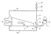
図1は流体機械1を示す。該機械1は車室2を持つ。内部車室3の内部に軸4が回転可能に配置されている。内部車室3は静翼5を、軸4は動翼6を有する。排気室7に熱交換器8が配置されている。熱交換器8は、流体機械1の排気室7内に配置せずともよい。
FIG. 1 shows a
主蒸気はボイラ(図示せず)から主蒸気入口管9を経て流体機械1に導入される。主蒸気の一部は分岐点10で分岐されて熱交換器8に導かれる。分岐点10の上流での主蒸気の温度は565℃であり、圧力は250バールである。主蒸気の残留部分、即ち熱交換器に導入されない主蒸気部分は、配管11を経て流体機械1に達する。この場合、主蒸気は主蒸気入口室12に達し、そこから、軸方向13に静翼5と動翼6を通って流れる。一対の静翼列と動翼列とから成る最終翼列14の後方で、膨張済みの冷却された主蒸気は排気室7に達する。その温度は330℃、圧力は55バールである。
Main steam is introduced into the
熱交換器8は、ここから出る流れ媒体が熱交換器8に流入する前に比べて少なくとも10℃、特に少なくとも20℃だけ冷却されるように設計されている。
The
かくして冷却された主蒸気は、排出管16を経て流体機械1の入口室17に達する。入口室17は、排出管16からやって来る冷却済み主蒸気が入口室17に達するよう、静翼輪18で、主蒸気入口室12から分離されている。冷却済み主蒸気は、そこから、熱的に大きく負荷される釣合いピストン19又は別の熱的に大きく負荷される箇所に達する。入口室17の軸4の熱的に大きく負荷される箇所は、冷却済み主蒸気で冷却される。
The main steam thus cooled reaches the
図2は冷却装置の原理図である。主蒸気は主蒸気入口管9を経て流体機械1に達する。主蒸気入口管9は、分岐点10の上流に位置する止め弁20を備える。分岐点10は配管15を経て熱交換器8に供給する主蒸気を分岐する。この主蒸気は、熱交換器8で冷却され、排出管16を経て入口室17に達する。矢印21で冷却蒸気21の流れ方向を示す。冷却蒸気は釣合いピストン19の周囲を流れ、その熱的に大きく負荷される箇所を冷却する。静翼輪18で、入口室17が主蒸気入口室21から分離されている。
FIG. 2 is a principle diagram of the cooling device. The main steam reaches the
主蒸気の一部は、主蒸気入口管9と配管11を経て流体機械1に達し、図2に示さない静翼と動翼を通り、矢印22の方向に流体機械1を貫流して流れ、流体機械1の排気室7から流出する。静翼輪18は、冷却蒸気を流体機械1に導入すべく設けている。ただ運転差圧を維持するため、用いた熱交換器8の圧力損失が、その静翼輪18での圧力低下より小さくなければならない。流体機械1の排気流23内に存在する熱交換器8は、配管15を経て到達する主蒸気を冷却し、余分な熱を排気に放出する。この熱は、場合により後置接続した再熱器(図示せず)で利用する。この結果、追加的な損失は生じない。
A part of the main steam reaches the
冷却に必要な主蒸気は、止め弁20の下流で取り出す。このため、全系統は自己制御され、補助的な遮断装置や調整装置は不要である。この結果、本発明による冷却方法は、図示しないボイラや他の構成要素と無関係である。換言すれば、必要な冷却蒸気は、タービン自体で発生され、外部の構成要素と無関係である。この方式は、冷却蒸気の発生が配管15内に組み込まれた熱交換器8で行われるので、単純で、経費的に有利である。
The main steam required for cooling is withdrawn downstream of the
1 流体機械、2 車室、7 排気室、8 熱交換器、9 主蒸気入口管、10 分岐点、12 主蒸気入口室、17 入口室、19 釣合いピストン、20 止め弁
DESCRIPTION OF
Claims (10)
Fluid machine according to one of claims 7 to 9, characterized in that the supply pipe (16) communicates with the balancing piston (19).
Applications Claiming Priority (1)
| Application Number | Priority Date | Filing Date | Title |
|---|---|---|---|
| EP03005070A EP1455066B1 (en) | 2003-03-06 | 2003-03-06 | Cooling of a turbine and method therefore |
Publications (2)
| Publication Number | Publication Date |
|---|---|
| JP2004340129A true JP2004340129A (en) | 2004-12-02 |
| JP3784808B2 JP3784808B2 (en) | 2006-06-14 |
Family
ID=32798793
Family Applications (1)
| Application Number | Title | Priority Date | Filing Date |
|---|---|---|---|
| JP2004060174A Expired - Fee Related JP3784808B2 (en) | 2003-03-06 | 2004-03-04 | Fluid machine and its cooling method |
Country Status (6)
| Country | Link |
|---|---|
| US (1) | US7264438B2 (en) |
| EP (1) | EP1455066B1 (en) |
| JP (1) | JP3784808B2 (en) |
| CN (1) | CN100420835C (en) |
| DE (1) | DE50312764D1 (en) |
| ES (1) | ES2344686T3 (en) |
Cited By (3)
| Publication number | Priority date | Publication date | Assignee | Title |
|---|---|---|---|---|
| JP2011074920A (en) * | 2009-09-30 | 2011-04-14 | Alstom Technology Ltd | Steam turbine including stress relaxation groove in rotor |
| JP2011080471A (en) * | 2009-10-12 | 2011-04-21 | Alstom Technology Ltd | High-temperature axial-flow steam turbine of radial direction supply type |
| JP2014527597A (en) * | 2011-08-30 | 2014-10-16 | シーメンス アクティエンゲゼルシャフト | Cooling for fluid machinery |
Families Citing this family (4)
| Publication number | Priority date | Publication date | Assignee | Title |
|---|---|---|---|---|
| JP4783053B2 (en) * | 2005-04-28 | 2011-09-28 | 株式会社東芝 | Steam turbine power generation equipment |
| US8167535B2 (en) * | 2008-07-24 | 2012-05-01 | General Electric Company | System and method for providing supercritical cooling steam into a wheelspace of a turbine |
| CH699978A1 (en) | 2008-11-26 | 2010-05-31 | Alstom Technology Ltd | Steam turbine. |
| EP2565401A1 (en) * | 2011-09-05 | 2013-03-06 | Siemens Aktiengesellschaft | Method for temperature balance in a steam turbine |
Family Cites Families (6)
| Publication number | Priority date | Publication date | Assignee | Title |
|---|---|---|---|---|
| US2552239A (en) * | 1946-10-29 | 1951-05-08 | Gen Electric | Turbine rotor cooling arrangement |
| US5778657A (en) * | 1995-09-22 | 1998-07-14 | Kabushiki Kaisha Toshiba | Combined cycle power plant |
| DE19620828C1 (en) * | 1996-05-23 | 1997-09-04 | Siemens Ag | Steam turbine shaft incorporating cooling circuit |
| US6792762B1 (en) * | 1999-11-10 | 2004-09-21 | Hitachi, Ltd. | Gas turbine equipment and gas turbine cooling method |
| EP1152125A1 (en) * | 2000-05-05 | 2001-11-07 | Siemens Aktiengesellschaft | Method and apparatus for the cooling of the inlet part of the axis of a steam turbine |
| EP1154123A1 (en) * | 2000-05-10 | 2001-11-14 | Siemens Aktiengesellschaft | Method of cooling the shaft of a high pressure steam turbine |
-
2003
- 2003-03-06 EP EP03005070A patent/EP1455066B1/en not_active Expired - Lifetime
- 2003-03-06 ES ES03005070T patent/ES2344686T3/en not_active Expired - Lifetime
- 2003-03-06 DE DE50312764T patent/DE50312764D1/en not_active Expired - Lifetime
-
2004
- 2004-03-01 CN CNB2004100073649A patent/CN100420835C/en not_active Expired - Fee Related
- 2004-03-02 US US10/791,088 patent/US7264438B2/en not_active Expired - Fee Related
- 2004-03-04 JP JP2004060174A patent/JP3784808B2/en not_active Expired - Fee Related
Cited By (3)
| Publication number | Priority date | Publication date | Assignee | Title |
|---|---|---|---|---|
| JP2011074920A (en) * | 2009-09-30 | 2011-04-14 | Alstom Technology Ltd | Steam turbine including stress relaxation groove in rotor |
| JP2011080471A (en) * | 2009-10-12 | 2011-04-21 | Alstom Technology Ltd | High-temperature axial-flow steam turbine of radial direction supply type |
| JP2014527597A (en) * | 2011-08-30 | 2014-10-16 | シーメンス アクティエンゲゼルシャフト | Cooling for fluid machinery |
Also Published As
| Publication number | Publication date |
|---|---|
| US7264438B2 (en) | 2007-09-04 |
| ES2344686T3 (en) | 2010-09-03 |
| JP3784808B2 (en) | 2006-06-14 |
| CN1526928A (en) | 2004-09-08 |
| CN100420835C (en) | 2008-09-24 |
| DE50312764D1 (en) | 2010-07-15 |
| US20040175264A1 (en) | 2004-09-09 |
| EP1455066B1 (en) | 2010-06-02 |
| EP1455066A1 (en) | 2004-09-08 |
Similar Documents
| Publication | Publication Date | Title |
|---|---|---|
| US7003956B2 (en) | Steam turbine, steam turbine plant and method of operating a steam turbine in a steam turbine plant | |
| KR960004214B1 (en) | Forced cooling device for steam turbine | |
| JP4662562B2 (en) | Steam turbine and operation method thereof | |
| US8858158B2 (en) | Steam turbine and steam turbine plant system | |
| CA2230341C (en) | Cooling steam system for steam cooled gas turbine | |
| JP5692966B2 (en) | Method and apparatus for cooling rotating parts inside a steam turbine | |
| JPH07301127A (en) | Gas turbine power plant, and cooling method for gas turbine power plant | |
| EP2354449B1 (en) | Method and apparatus for double flow steam turbine first stage cooling | |
| JP6479386B2 (en) | Steam turbine | |
| JP2004340129A (en) | Fluid machine, and method for cooling the same | |
| BRPI0613011A2 (en) | Method for starting a steam turbine installation | |
| US11352910B2 (en) | Steam turbine and method for operating same | |
| JP2007051636A (en) | Turbo machine for low temperature application | |
| WO2017169590A1 (en) | Plant and operation method therefor | |
| JP2016125355A (en) | Turbine cooling device | |
| JP2019508619A (en) | Gas turbine with axial thrust piston and radial bearing | |
| KR102040424B1 (en) | Seal device | |
| JP5901194B2 (en) | Gas turbine cooling system and gas turbine cooling method | |
| US20110030335A1 (en) | Combined-cycle steam turbine and system having novel cooling flow configuration | |
| JP6511519B2 (en) | Controlled cooling of a turbine shaft | |
| US20210262361A1 (en) | Turbine | |
| JP7263514B2 (en) | Steam turbine and its operating method | |
| JPH1047082A (en) | Steam cooling gas turbine | |
| JP2021046822A (en) | Turbine and manufacturing method of the same | |
| JP2012057584A (en) | Steam turbine |
Legal Events
| Date | Code | Title | Description |
|---|---|---|---|
| A131 | Notification of reasons for refusal |
Free format text: JAPANESE INTERMEDIATE CODE: A131 Effective date: 20050818 |
|
| A521 | Written amendment |
Free format text: JAPANESE INTERMEDIATE CODE: A523 Effective date: 20051108 |
|
| TRDD | Decision of grant or rejection written | ||
| A01 | Written decision to grant a patent or to grant a registration (utility model) |
Free format text: JAPANESE INTERMEDIATE CODE: A01 Effective date: 20060216 |
|
| A61 | First payment of annual fees (during grant procedure) |
Free format text: JAPANESE INTERMEDIATE CODE: A61 Effective date: 20060315 |
|
| R150 | Certificate of patent or registration of utility model |
Free format text: JAPANESE INTERMEDIATE CODE: R150 |
|
| FPAY | Renewal fee payment (event date is renewal date of database) |
Free format text: PAYMENT UNTIL: 20100324 Year of fee payment: 4 |
|
| FPAY | Renewal fee payment (event date is renewal date of database) |
Free format text: PAYMENT UNTIL: 20100324 Year of fee payment: 4 |
|
| FPAY | Renewal fee payment (event date is renewal date of database) |
Free format text: PAYMENT UNTIL: 20110324 Year of fee payment: 5 |
|
| FPAY | Renewal fee payment (event date is renewal date of database) |
Free format text: PAYMENT UNTIL: 20110324 Year of fee payment: 5 |
|
| FPAY | Renewal fee payment (event date is renewal date of database) |
Free format text: PAYMENT UNTIL: 20120324 Year of fee payment: 6 |
|
| FPAY | Renewal fee payment (event date is renewal date of database) |
Free format text: PAYMENT UNTIL: 20130324 Year of fee payment: 7 |
|
| FPAY | Renewal fee payment (event date is renewal date of database) |
Free format text: PAYMENT UNTIL: 20130324 Year of fee payment: 7 |
|
| FPAY | Renewal fee payment (event date is renewal date of database) |
Free format text: PAYMENT UNTIL: 20140324 Year of fee payment: 8 |
|
| R250 | Receipt of annual fees |
Free format text: JAPANESE INTERMEDIATE CODE: R250 |
|
| R250 | Receipt of annual fees |
Free format text: JAPANESE INTERMEDIATE CODE: R250 |
|
| R250 | Receipt of annual fees |
Free format text: JAPANESE INTERMEDIATE CODE: R250 |
|
| LAPS | Cancellation because of no payment of annual fees |