JP2004339946A - Fuel injection valve - Google Patents
Fuel injection valve Download PDFInfo
- Publication number
- JP2004339946A JP2004339946A JP2003134406A JP2003134406A JP2004339946A JP 2004339946 A JP2004339946 A JP 2004339946A JP 2003134406 A JP2003134406 A JP 2003134406A JP 2003134406 A JP2003134406 A JP 2003134406A JP 2004339946 A JP2004339946 A JP 2004339946A
- Authority
- JP
- Japan
- Prior art keywords
- fuel
- heater
- valve
- injection valve
- fuel injection
- Prior art date
- Legal status (The legal status is an assumption and is not a legal conclusion. Google has not performed a legal analysis and makes no representation as to the accuracy of the status listed.)
- Pending
Links
Images


Abstract
Description
【0001】
【発明の属する技術分野】
本発明は内燃機関に燃料を噴射する燃料噴射弁に関し、詳しくは燃料を微粒化するためのヒータ構造に関する。
【0002】
【従来の技術】
近年、車両の排ガス規制が強化されており、排ガス中に含まれる有害成分を低減することが大きな課題となっている。この対策として、燃料噴射弁の噴孔から噴射する燃料噴霧を微粒化することが有効であることが知られ、加熱した燃料を噴射し、燃料を減圧沸騰させて燃料噴霧を微粒化する燃料噴射弁が提案されている(例えば、特許文献1等)。特に、冷間始動時には、噴射した燃料が微粒化しにくく、排ガス中の有害成分、例えば、HCやPMといった成分が増加しやすいので、冷間始動時に燃料を加熱して微粒化すると排ガス中の有害成分低減に効果的である。
【0003】
【特許文献1】
特開2002−295332号公報
【0004】
特許文献1に開示される燃料噴射弁100では、図8に示すように、噴孔110を開閉する弁部材120と、弁部材120を駆動するためのコイル140と、燃料を加熱するためのヒータ150を有している。コイル140へ電流を供給するためのターミナル131はコネクタ130に埋設されており、ヒータ150の電極151へ電流を供給するためのターミナル152は電線153によってコネクタ170の図示しないターミナルと電気的に接続されている。
【0005】
【発明が解決しようとする課題】
ここで、コイル140とヒータ150に別々のコネクタ130、170から電源を供給しているのは、以下の理由による。すなわち、ヒータ150は、被水しないように金属製のケース部材160に収容されているが、ヒータ150の発熱によりケース部材160およびターミナル152も高温になる。このため、樹脂製であるコネクタ130にターミナル152を収容することは困難であり、ケース部材160の蓋に設けた筒状部161から電線153を取り出して、外部のコネクタ170に接続するようになっていた。
【0006】
しかしながら、上記構成では、ヒータ150で発生する熱が外部へ伝達されてしまい、燃料の加熱に有効に利用されているとはいえない。また、ヒータ用コネクタ170とコイル用コネクタ130が別体であることは、エンジン搭載時に電気配線が複雑になるばかりでなく、体格が大きくなり、燃料噴射弁の製造コストも高くなるという問題があった。
【0007】
本発明の目的は、ヒータの発熱を燃料に有効に伝達し、外部への伝熱を抑制して、燃料の加熱を効果的に行うこと、さらには、ケース部材やターミナル等が高温となるのを抑制して、ヒータ用コネクタとコイル用コネクタの一体化を可能にすることにあり、構成が簡易でコンパクトであり、製造コストを抑制できる噴射弁を提供する。
【0008】
【課題を解決するための手段】
請求項1記載の発明において、燃料噴射弁は、燃料通路から供給された燃料を噴射する噴孔が形成され、該噴孔の開閉がバルブニードルにより切り換え自在な噴射ノズル部と、コイルへの通電により電磁吸引力を発生させて上記バルブニードルを駆動する電磁駆動部と、上記燃料通路を流通する燃料を加熱する加熱手段を有している。
上記噴射ノズル部は、上記バルブニードルが収容されるケース部材を有し、このケース部材と上記バルブニードル外周面との隙間に燃料を導入することにより、上記燃料通路の一部となる燃料溜まりを構成している。そして、上記加熱手段を、上記燃料溜まりの燃料に浸漬させた状態で配置したものである。
【0009】
上記構成によれば、上記加熱手段を上記燃料溜まりの燃料液中に接触させて配したので、上記加熱手段の熱を燃料に伝達しやすい。従って、噴孔に供給される燃料を効果的に加熱して、冷間始動時における燃料の微粒化を促進できる。また、燃料液が介在しているので、他部材への伝熱が抑制され、設計の自由度が向上する。よって、例えば、ヒータ用コネクタとコイル用コネクタを一体化して構成をコンパクトにすることが可能となり、製造コストを抑制できる。
【0010】
請求項2記載の燃料噴射弁は、上記バルブニードルが収容されるケース部材の一部を拡径し、該拡径部と上記バルブニードル外周面との隙間を上記燃料溜まりとする。また、上記加熱手段を上記バルブニードルの外周を取り囲むように配置し、上記加熱手段の内周面側の空間と外周面側の空間とを互いに連通させている。
【0011】
具体的には、上記バルブニードルの周囲に拡径部を設けて上記加熱手段を配置し、燃料を充填することで、容易に上記燃料溜まりに上記加熱手段を浸漬させることができる。この時、上記加熱手段の内周面側の空間と外周面側の空間とを連通させることで、両空間に燃料を流通させ、効率よく燃料を加熱することができる。
【0012】
請求項3記載の燃料噴射弁は、上記加熱手段に接続されるターミナルの基端部を、上記燃料溜まりの燃料に浸漬させた状態で配置する。
【0013】
上記構成によれば、上記ターミナルの基端部を燃料液に接触させることで、該一端部の温度上昇を抑制できる。よって、上記一端部からの熱伝導で上記ターミナルの他端部が高温となるのを抑制できるので、例えば、ヒータ用コネクタをコイル用コネクタに一体に構成することが可能となる。
【0014】
請求項4記載の燃料噴射弁は、上記加熱手段に接続されるターミナルの基端部と先端部との間に、該ターミナルからの熱を吸収する吸熱手段を設けている。
【0015】
上記構成によれば、上記吸熱手段により、上記基端部からの熱伝導がさらに抑制されるので、上記ターミナルの先端部の温度上昇を抑制する効果を高めることができる。
【0016】
請求項5記載の燃料噴射弁は、上記加熱手段に接続されるターミナルの先端部と、上記電磁駆動部のコイル通電用のターミナルの先端部とが収容される一体型コネクタを設ける。
【0017】
上記構成によれば、上記加熱手段への電源供給部と、上記電磁駆動部への電源供給部を1つのコネクタに集約できるので、構成が簡易になり、小型化が可能で製造コストが低減できる。
【0018】
請求項6記載の燃料噴射弁は、上記加熱手段に接続されるターミナルを、基端部側と上記先端部側の2部材に分割して構成する。そして、上記基端部側の部材を上記バルブニードルを収容するバルブサブアッセンブリに、上記先端部側の部材を上記コイルを収容するコイルアッセンブリに設けて、これらコイルアッセンブリとバルブサブアッセンブリとを組み付けることにより、上記ターミナルを構成する上記2部材を電気的に接続する。
【0019】
上記加熱手段に通電するためのターミナルと、上記コイルに通電するためのターミナルとを一体型コネクタに集約する場合、上記加熱手段に通電するためのターミナルを2分割すると、その一方と上記コイル用のターミナルとを予め樹脂モ−ルドしてコネクタを形成することができる。これをコイルアッセンブリとしてバルブサブアッセンブリに組み付けることにより、容易に燃料噴射弁を製作するとともに、上記2部材を接続して上記ターミナルとすることができる。
【0020】
【発明の実施の形態】
以下に本発明の実施の形態を図面に基づいて説明する。
(第1実施形態)
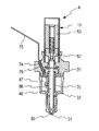
本発明の第1実施形態による燃料噴射弁構造を図1に示す。図1において、燃料噴射弁1は、ボディパイプ10、ハウジング20、ノズルボディ30、ケース部材としてのボディケース33、弁部材としてのバルブニードル40、噴孔31を開閉して燃料を噴射する噴射ノズル部41、バルブニードル40を駆動する電磁駆動部60、加熱手段としてのヒータ70などから構成されている。
【0021】
ボディパイプ10は、バルブニードル40の基端部(図の上端部)が収容されるハウジング20の上端開口部内に挿通固定される。ボディパイプ10は概略円筒形状であり、筒内部に、図の上方から固定鉄心53およびコア52を収容している。固定鉄心53は円筒状であり、内部にスプリング51およびその付勢力を調整するアジャスティングパイプ54を収容している。固定鉄心53の下面に対向して位置するコア52は、磁性材料から形成されており、コア52と固定鉄心53とは当接可能である。コア52は大小二段径の筒状で、小径の下端部がバルブニードル40の基端部にレーザ溶接等により固定されて、一体に上下動可能となっている。
【0022】
ボディパイプ10は磁性部と非磁性部とからなり、例えば複合磁性材で形成されている。ボディパイプ10は、下方の噴射ノズル部41側から第1磁性部10a、磁気抵抗部としての非磁性部10b、第2磁性部10cの順で一体成形されている。第1磁性部10aおよび第2磁性部10cは磁性化されており、非磁性部10cはボディパイプ10の一部を加熱して非磁性化されている。非磁性部10bは、第1磁性部10aと第2磁性部10cとの間で磁束が短絡することを防ぐ。
【0023】
スプリング51は、一方の端部(図の上端部)がアジャスティングパイプ54に、他方の端部(図の下端部)がコア52の段部に当接し、両者の間に保持されている。スプリング51はバルブニードル40を噴孔31方向、すなわち閉弁方向に付勢しており、アジャスティングパイプ54の圧入量を調節することによりスプリング51の荷重を変更できる。
【0024】
アジャスティングパイプ54の筒内、固定鉄心53およびコア52の筒内は、それぞれ燃料が流通可能な燃料通路81および燃料通路82としてある。燃料通路81は、ボディパイプ10の上端部に固定される燃料導入管21に接続している。また、コア52の下端部側壁には、燃料通路81、82を通過した燃料が流通可能な燃料流通孔84が貫通形成されている。従って、燃料導入管21からフィルタ22を介して導入される燃料が、燃料通路81、82および燃料流通孔84を経てハウジング20内の燃料通路83へ供給される。
【0025】
噴射ノズル部41は、大小二段径のボディケース33の下半部に収容されるノズルボディ30とバルブニードル40などから構成される。ボディケース33はハウジング20の下端部にレーザ溶接等により固定されており、バルブニードル40先端部(図の下端部)がノズルボディ30内に位置している。ノズルボディ30の先端部(図の下端部)を貫通して噴孔31が形成され、噴孔31入口側のノズルボディ30内周部には弁座部32が設けられている。バルブニードル40には弁座部32に着座可能な当接部42が形成されている。当接部42が弁座部32に着座して噴孔31が閉塞されると燃料噴射が遮断される。
【0026】
電磁駆動装置60は、ボディパイプ10の外周側に固定鉄心53を包囲するように配設されている。電磁駆動装置60は、コイルアッセンブリ11ならびに磁気回路を構成する磁性材料からなるヨーク12と、ボディパイプ10内の固定鉄心53、コア52などから構成されている。コイルアッセンブリ11はコイル61ならびにコイル61が巻回されるボビン62から構成される。コイル61に通電することにより固定鉄心53に電磁吸引力が発生し、コア52とともにバルブニードル40を図1の上方へ吸引する。
【0027】
コイルアッセンブリ11の外周には、樹脂モールドによりコネクタ13が形成されている。コネクタ13内にはコイル61に電気的に接続されたコイルターミナル14と、ヒータ70に電気的に接続されたヒータターミナル15が埋設されている。コイルターミナル14ならびにヒータターミナル15は図示しないエンジン制御装置に接続され、エンジンの運転状況に応じてエンジン制御装置から出力された所定の電流値がコイルターミナル14ならびにヒータターミナル15に印加される。
【0028】
ヒータ70は筒状で、拡径部としてのボディケース33の上半部内に、バルブニードル40の外周を包囲するように配設されている。ヒータ70の上端部には図示しない凹部が設けられており、該凹部にヒータ固定治具71がはめ込まれている。ヒータ固定治具71はレーザ溶接等によりハウジング20の下端開口部内に固定されている。ボディケース33の上半部内の空間は、燃料溜まり87としてあり、ボディケース33の段付部に形成される通路89によってノズルボディ30内の燃料通路88と連通している。燃料溜まり87は、ヒータ70の設置によってその内周面側と外周面側に区画されており、ヒータ70内周面とバルブニードル40外周面との間に形成される燃料通路86は、図示しない通路によって、または通路89によって外周側の燃料溜まり87と連通している。燃料通路86の上端側はヒータ固定治具71内の燃料通路85に連通している。
【0029】
ヒータ70は、例えば、セラミックヒータからなり、発熱抵抗体をセラミックで焼結し円筒状に一体成形した公知の構造を有している。なお、セラミック等により形成されたヒータ70と、金属で構成されたハウジング20等の周囲部材とは線膨張係数が異なるため、ヒータ70の発熱時には熱膨張差が生じ、ヒータの割れ、ぐらつき等の発生が懸念される。そのため、ヒータ70は台座72を介して皿状のスプリング73で図中下方に付勢固定されている。このようにすることで、ヒータ70の発熱によりヒータ70と金属から成る周囲部材の間に熱膨張差が生じてもスプリング73が伸び縮みすることにより吸収できる。
【0030】
ヒータ70にはヒータターミナル15が溶接等により固定されている。ヒータターミナル15の基端部は燃料溜まり87内に位置し、先端部は、金属製のハウジング20に開けられた貫通穴74を通してコネクタ13内に延び、外部に取り出されている。貫通穴74は、例えば、絶縁性のあるガラスを用いたハーメチックシール75等により封止されている。ハーメチックシール75はハウジング20の内部と外部の封止、ハウジング20とヒータターミナル15の絶縁を行っている。また、金属製のハウジング20が吸熱手段として機能し、ヒータターミナル15の先端部側が基端部側からの熱伝導により温度上昇するのを抑制する。
【0031】
次に、本実施形態の燃料噴射弁1の組付け手順について説明する。まず、図2に示すバルブサブアッセンブリAを製造する。バルブサブアッセンブリAは、ハウジング20の上端側にコア52、固定鉄心53などを収容するボディパイプ10を、下端側にニードルバルブ40、ヒータ70、ノズルボディ30などを収容するボディケース33を固定することにより構成される。次に、図3に示すように、電磁駆動装置60を構成するコイルアッセンブリ11を、図の上方より組み付けた後、ヨーク12をコイルアッセンブリ11の外周部を覆うように固定し、バルブアッセンブリBとする。その後、コイルアッセンブリ11の外周を覆うように樹脂モールドしてコネクタ13を成型し、図1の燃料噴射弁1が完成する。各アッセンブリの詳細構成は前述した通りであり省略する。
【0032】
上記構成において、コイルターミナル14に電流が印加されると固定鉄心53に電磁吸引力が発生し、コア52ならびにコア52に接続されたバルブニードル40が図1の上方に吸引され、噴孔31の開弁が行われる。燃料通路81、82、84を通過した燃料は、ハウジング20の燃料通路83、台座72の内周部に形成された燃料通路85、ヒータ70内周面とバルブニードル40との間に形成された燃料通路86を経て、または図示しないヒータ70の内周面側と外周面側とを連通する燃料通路から、ボディケース33とヒータ70外周面によって形成される燃料溜まり87、通路89を通って、ノズルボディ30内部の燃料通路88へと導かれる。燃料通路88内の燃料は、バルブニードル40の上方への移動に伴って弁座部32と当接部42の間に形成される燃料通路を通って、噴孔31より噴射される。
【0033】
ここで、冷間始動時等において、ヒータターミナル15に電流が印加されるとヒータ70が発熱し、燃料通路86および燃料溜まり87内にある燃料が加熱される。従って、加熱された燃料を噴孔31より噴射することができるので、微粒化が促進され、排ガス中に含まれる有害成分を低減することができる。
【0034】
しかも、ヒータ70が、燃料溜まり87および燃料通路86を流通する燃料液中に浸された状態となっているので、外部への放熱を抑制しつつ燃料の加熱を効率よく行うことができる。さらに、ヒータターミナル15は、基端部が燃料溜まり87の燃料液中に浸されて温度上昇しにくくなっており、また、吸熱部となるハウジング20内を設けたので、先端部が高温となりにくい。よって、コイルターミナル14と一体のコネクタ13に収容することができる。
【0035】
そして、コイル61に電気的に接続されたコイルターミナル14と、ヒータ70に電気的に接続されたヒータターミナル15を、1つのコネクタ13に一体化したので、燃料噴射弁に接続するコネクタが1箇所で済み、電気配線が簡素化できる。また、上記図8の従来構成においては2箇所にあったコネクタが1つにまとめられたので、燃料噴射弁としての体格がコンパクトになり、製造コストも抑えることができる。
【0036】
(第2実施形態)
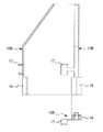
図4に第2実施形態を示す。燃料噴射弁1の基本的な構造は第1実施形態と同様であるので、相違点を中心に説明する。上記第1実施形態の燃料噴射弁1は、バルブサブアッセンブリAとコイルアッセンブリ11を組み付けた後、樹脂モ−ルドして一体化されるが、図4に示す本実施形態の燃料噴射弁1は、ヒータターミナル15を2部材15A、15Bに分割して予めコネクタ13を形成することにより、バルブサブアッセンブリA´とコイルアッセンブリ11´とが分解可能である。
【0037】
図5にバルブサブアッセンブリA´の構造を示す。バルブサブアッセンブリA´は、ニードルバルブ40、ヒータ70、ノズルボディ30、ボディケース33、ボディパイプ10などから構成される。ヒータ70には、ヒータターミナル15の基端部側部材としてのオスピン15Aが電気的に接続されており、ハウジング20に開けられた貫通穴74から、噴射弁外部に取り出されている。貫通穴74はハーメチックシール75等により封止されている。バルブサブアッセンブリA´の組み付け手順は上述した第1実施形態と同様である。
【0038】
図6にコイルアッセンブリ11´の構造と組立て手順を示す。まず、図6(a)に示すようにボビン62にコイル61を巻回し、ボビン62に固定されたコイルターミナル14とコイル61を電気的に接続する。次工程で、図6(b)に示すように、ヒータターミナル15の先端部側部材としてのメスピン15Bを、ボビン62の下端から延出形成された固定部63に熱溶着等により固定する。その後、図6(c)に示すように、コイル61、ボビン62、コイルターミナル14、ヒータターミナル15となるメスピン15Bの外周部を樹脂モールドで覆って、コネクタ13を形成し、コイルアッセンブリ11´が完成する。
【0039】
図7に、ヒータターミナル15の先端部側部材としてのメスピン15Bの構造を示す。ヒータターミナル15となるメスピン15Bには、バルブサブアッセンブリA´に設けられるヒータターミナル15の基端部側部材としてのオスピン15Aと接続するためのメスピン部16と、ボビン62に固定するための固定部17が形成されている。
【0040】
以上のように製造されたバルブサブアッセンブリA´とコイルアッセンブリ11´は、図5に示すバルブサブアッセンブリA´に、噴孔31の反対側(図の上側)から、図6(c)に示すコイルアッセンブリ11´を組み付けることで一体化される。ヒータ70は、ヒータターミナル15の基端部側のオスピン15Aと先端部側のメスピン15Bが結合されることにより、電気的に接続される。
【0041】
本実施形態の構成によっても、上記第1の実施形態と同様の効果が得られる。さらに、ヒータターミナル15を、基端部側のオスピン15Aと先端部側のメスピン15Bに2分割し、それぞれをバルブサブアッセンブリA´とコイルアッセンブリ11´に収容する構成としたので、予めコイルアッセンブリ11´にコネクタ13を形成することができる。そして、バルブサブアッセンブリA´とコイルアッセンブリ11´を組み付け、オスピン15Aとメスピン15Bを結合することで、容易にヒータターミナル15を形成し、電源供給部を完成することができるので、製作工程が簡易にできる。本実施の形態では、廃棄時に主に樹脂部から成るコイルサブアッセンブリ11´と、金属から成るバルブサブアッセンブリA´が容易に分解でき、リサイクル性が向上する。
【0042】
以上のように、本発明によれば、ヒータを内蔵する燃料噴射弁において、燃料の加熱を効果的に行うことができ、さらに、ヒータ用コネクタとコイル用コネクタを一体化することで、構成が簡易でコンパクトであり、低コストな燃料噴射弁とすることができる。
【図面の簡単な説明】
【図1】本発明の第1実施形態の燃料噴射弁の全体断面図である。
【図2】第1実施形態の燃料噴射弁の組み付け手順を説明するための図で、燃料噴射弁のバルブサブアッセンブリの断面図である。
【図3】第1実施形態の燃料噴射弁の組み付け手順を説明するための図で、燃料噴射弁のバルブアッセンブリの断面図である。
【図4】本発明の第2実施形態の燃料噴射弁の全体断面図である。
【図5】第2実施形態の燃料噴射弁の組み付け手順を説明するための図で、燃料噴射弁のバルブサブアッセンブリの断面図である。
【図6】(a)〜(c)は第2実施形態のコイルアッセンブリの組み付け手順を説明するための断面図である。
【図7】第2実施形態の燃料噴射弁においてヒータターミナルとなるメスピン構成を示す拡大断面図である。
【図8】従来の燃料噴射弁の全体断面図である。
【符号の説明】
1 燃料噴射弁
10 ボディパイプ
13 コネクタ
14 コイルターミナル
15 ヒータターミナル
15A オスピン(基端側部材)
15B メスピン(先端側部材)
20 ハウジング(吸熱手段)
30 ノズルボディ
31 噴孔
33 ボディケース(ケース部材)
40 バルブニードル
41 噴射ノズル部
51 スプリング
52 コア
53 固定鉄心
60 電磁駆動装置
61 コイル
70 ヒータ(加熱手段)
74 貫通孔
81、82、83、85、86、88 燃料通路
87 燃料溜まり[0001]
TECHNICAL FIELD OF THE INVENTION
The present invention relates to a fuel injection valve for injecting fuel into an internal combustion engine, and more particularly, to a heater structure for atomizing fuel.
[0002]
[Prior art]
In recent years, regulations on exhaust gas from vehicles have been tightened, and reducing harmful components contained in exhaust gas has become a major issue. As a countermeasure, it has been known that it is effective to atomize the fuel spray injected from the injection hole of the fuel injection valve. Injecting heated fuel, the fuel is decompressed and boiled, and the fuel spray is atomized. A valve has been proposed (for example, Patent Document 1). In particular, during a cold start, the injected fuel is hard to atomize, and harmful components in the exhaust gas, for example, components such as HC and PM, are likely to increase. It is effective in reducing components.
[0003]
[Patent Document 1]
JP-A-2002-295332
In the
[0005]
[Problems to be solved by the invention]
Here, power is supplied to the
[0006]
However, in the above configuration, the heat generated by the
[0007]
An object of the present invention is to effectively transmit the heat generated by the heater to the fuel, suppress the heat transfer to the outside, and effectively heat the fuel. The present invention provides an injection valve that has a simple configuration, is compact, and can suppress the manufacturing cost.
[0008]
[Means for Solving the Problems]
According to the first aspect of the present invention, the fuel injection valve has an injection hole for injecting the fuel supplied from the fuel passage, and an injection nozzle portion whose opening and closing can be switched by a valve needle. An electromagnetic drive unit for generating an electromagnetic attraction force to drive the valve needle, and a heating unit for heating the fuel flowing through the fuel passage.
The injection nozzle portion has a case member in which the valve needle is housed, and introduces fuel into a gap between the case member and the outer peripheral surface of the valve needle to form a fuel pool that becomes a part of the fuel passage. Make up. The heating means is disposed in a state where the heating means is immersed in the fuel in the fuel pool.
[0009]
According to the above configuration, since the heating means is disposed in contact with the fuel liquid in the fuel reservoir, the heat of the heating means can be easily transmitted to the fuel. Therefore, it is possible to effectively heat the fuel supplied to the injection holes, and to promote atomization of the fuel during the cold start. Further, since the fuel liquid is interposed, heat transfer to other members is suppressed, and the degree of freedom in design is improved. Therefore, for example, the heater connector and the coil connector can be integrated to make the configuration compact, and the manufacturing cost can be suppressed.
[0010]
In the fuel injection valve according to the second aspect, the diameter of a part of the case member accommodating the valve needle is enlarged, and a gap between the enlarged diameter portion and the outer peripheral surface of the valve needle is used as the fuel reservoir. Further, the heating means is arranged so as to surround the outer periphery of the valve needle, and the space on the inner peripheral surface side and the space on the outer peripheral surface side of the heating means communicate with each other.
[0011]
Specifically, by providing an enlarged diameter portion around the valve needle, disposing the heating means, and filling the fuel, the heating means can be easily immersed in the fuel reservoir. At this time, by allowing the space on the inner peripheral surface side and the space on the outer peripheral surface side of the heating means to communicate with each other, fuel can flow through both spaces, and the fuel can be efficiently heated.
[0012]
According to a third aspect of the present invention, in the fuel injection valve, a base end portion of the terminal connected to the heating means is disposed so as to be immersed in the fuel in the fuel reservoir.
[0013]
According to the configuration, by bringing the base end of the terminal into contact with the fuel liquid, it is possible to suppress a rise in the temperature of the one end. Therefore, it is possible to suppress the temperature of the other end of the terminal from becoming high due to the heat conduction from the one end, so that, for example, the heater connector can be integrally formed with the coil connector.
[0014]
According to a fourth aspect of the present invention, the fuel injection valve includes a heat absorbing means for absorbing heat from the terminal between a base end and a distal end of the terminal connected to the heating means.
[0015]
According to the above configuration, heat conduction from the base end is further suppressed by the heat absorbing means, so that the effect of suppressing a rise in temperature at the distal end of the terminal can be enhanced.
[0016]
According to a fifth aspect of the present invention, there is provided a fuel injection valve provided with an integrated connector for accommodating a distal end of a terminal connected to the heating means and a distal end of a terminal for energizing a coil of the electromagnetic drive unit.
[0017]
According to the above configuration, the power supply unit for the heating unit and the power supply unit for the electromagnetic drive unit can be integrated into one connector. Therefore, the configuration is simplified, the size can be reduced, and the manufacturing cost can be reduced. .
[0018]
A fuel injection valve according to a sixth aspect of the present invention is configured such that a terminal connected to the heating means is divided into two members, a base end side and the distal end side. And, the member on the base end side is provided in a valve sub-assembly for housing the valve needle, and the member on the distal end side is provided in a coil assembly for housing the coil, and the coil assembly and the valve sub-assembly are assembled. Thereby, the two members constituting the terminal are electrically connected.
[0019]
When the terminal for energizing the heating unit and the terminal for energizing the coil are integrated into an integrated connector, the terminal for energizing the heating unit is divided into two, and one of the terminals for the coil is connected to the terminal for the coil. The terminal can be resin-molded in advance to form a connector. By assembling this as a coil assembly with the valve subassembly, the fuel injection valve can be easily manufactured, and the two members can be connected to form the terminal.
[0020]
BEST MODE FOR CARRYING OUT THE INVENTION
Embodiments of the present invention will be described below with reference to the drawings.
(1st Embodiment)
FIG. 1 shows a fuel injection valve structure according to a first embodiment of the present invention. In FIG. 1, a
[0021]
The
[0022]
The
[0023]
The
[0024]
The inside of the cylinder of the adjusting
[0025]
The
[0026]
The
[0027]
A
[0028]
The
[0029]
The
[0030]
The
[0031]
Next, a procedure for assembling the
[0032]
In the above configuration, when a current is applied to the
[0033]
Here, when a current is applied to the
[0034]
Moreover, since the
[0035]
Since the
[0036]
(2nd Embodiment)
FIG. 4 shows a second embodiment. Since the basic structure of the
[0037]
FIG. 5 shows the structure of the valve subassembly A ′. The valve subassembly A ′ includes a
[0038]
FIG. 6 shows the structure and assembling procedure of the coil assembly 11 '. First, as shown in FIG. 6A, the
[0039]
FIG. 7 shows the structure of a
[0040]
The valve subassembly A 'and the coil assembly 11' manufactured as described above are connected to the valve subassembly A 'shown in FIG. 5 from the side opposite to the injection hole 31 (upper side in the figure), as shown in FIG. It is integrated by assembling the coil assembly 11 '. The
[0041]
According to the configuration of the present embodiment, the same effect as in the first embodiment can be obtained. Further, the
[0042]
As described above, according to the present invention, in a fuel injection valve having a built-in heater, heating of fuel can be effectively performed, and furthermore, a configuration is achieved by integrating a heater connector and a coil connector. A simple, compact, and low-cost fuel injection valve can be provided.
[Brief description of the drawings]
FIG. 1 is an overall sectional view of a fuel injection valve according to a first embodiment of the present invention.
FIG. 2 is a diagram for explaining a procedure for assembling the fuel injection valve according to the first embodiment, and is a cross-sectional view of a valve subassembly of the fuel injection valve.
FIG. 3 is a view for explaining an assembling procedure of the fuel injection valve according to the first embodiment, and is a cross-sectional view of a valve assembly of the fuel injection valve.
FIG. 4 is an overall sectional view of a fuel injection valve according to a second embodiment of the present invention.
FIG. 5 is a view for explaining a procedure of assembling the fuel injection valve according to the second embodiment, and is a cross-sectional view of a valve subassembly of the fuel injection valve.
FIGS. 6A to 6C are cross-sectional views illustrating a procedure of assembling the coil assembly according to the second embodiment.
FIG. 7 is an enlarged sectional view showing a female pin configuration serving as a heater terminal in the fuel injection valve of the second embodiment.
FIG. 8 is an overall sectional view of a conventional fuel injection valve.
[Explanation of symbols]
DESCRIPTION OF
15B female pin (tip member)
20 Housing (heat absorbing means)
30
40
74 Through-
Claims (6)
コイルへの通電により電磁吸引力を発生させて上記バルブニードルを駆動する電磁駆動部と、
上記燃料通路を流通する燃料を加熱する加熱手段を具備する燃料噴射弁において、
上記バルブニードルが収容されるケース部材と上記バルブニードル外周面との隙間に燃料を導入して上記燃料通路の一部となる燃料溜まりを構成し、上記加熱手段を、上記燃料溜まりの燃料に浸漬させた状態で配置することを特徴とする燃料噴射弁。An injection nozzle for forming an injection hole for injecting fuel supplied from the fuel passage, wherein the opening and closing of the injection hole can be switched by a valve needle;
An electromagnetic drive unit that drives the valve needle by generating an electromagnetic attraction force by energizing the coil;
In a fuel injection valve including a heating unit that heats fuel flowing through the fuel passage,
Fuel is introduced into a gap between the case member accommodating the valve needle and the outer peripheral surface of the valve needle to form a fuel reservoir that becomes a part of the fuel passage, and the heating means is immersed in the fuel in the fuel reservoir. A fuel injection valve, wherein the fuel injection valve is disposed in a state where the fuel injection valve is disposed.
Priority Applications (1)
| Application Number | Priority Date | Filing Date | Title |
|---|---|---|---|
| JP2003134406A JP2004339946A (en) | 2003-05-13 | 2003-05-13 | Fuel injection valve |
Applications Claiming Priority (1)
| Application Number | Priority Date | Filing Date | Title |
|---|---|---|---|
| JP2003134406A JP2004339946A (en) | 2003-05-13 | 2003-05-13 | Fuel injection valve |
Publications (1)
| Publication Number | Publication Date |
|---|---|
| JP2004339946A true JP2004339946A (en) | 2004-12-02 |
Family
ID=33524977
Family Applications (1)
| Application Number | Title | Priority Date | Filing Date |
|---|---|---|---|
| JP2003134406A Pending JP2004339946A (en) | 2003-05-13 | 2003-05-13 | Fuel injection valve |
Country Status (1)
| Country | Link |
|---|---|
| JP (1) | JP2004339946A (en) |
Cited By (3)
| Publication number | Priority date | Publication date | Assignee | Title |
|---|---|---|---|---|
| JP2017524860A (en) * | 2014-07-15 | 2017-08-31 | デルフィ・インターナショナル・オペレーションズ・ルクセンブルク・エス・アー・エール・エル | Fuel injector |
| CN107567540A (en) * | 2015-04-14 | 2018-01-09 | Ge延巴赫两合无限公司 | The component being made up of cylinder head and fuel injector |
| KR20180138246A (en) * | 2017-06-19 | 2018-12-31 | 주식회사 유니크 | Hydrogen control valve |
Citations (4)
| Publication number | Priority date | Publication date | Assignee | Title |
|---|---|---|---|---|
| JPH0433413Y2 (en) * | 1985-12-14 | 1992-08-11 | ||
| JP2000507663A (en) * | 1996-03-29 | 2000-06-20 | シーメンス オートモーティブ コーポレイション | Fuel injector with built-in heater |
| JP2000508041A (en) * | 1997-07-23 | 2000-06-27 | シーメンス オートモーティブ コーポレイション | Fuel injector with internal heater |
| JP2000508042A (en) * | 1997-07-23 | 2000-06-27 | シーメンス オートモーティブ コーポレイション | Fuel preheating method with internal heater |
-
2003
- 2003-05-13 JP JP2003134406A patent/JP2004339946A/en active Pending
Patent Citations (4)
| Publication number | Priority date | Publication date | Assignee | Title |
|---|---|---|---|---|
| JPH0433413Y2 (en) * | 1985-12-14 | 1992-08-11 | ||
| JP2000507663A (en) * | 1996-03-29 | 2000-06-20 | シーメンス オートモーティブ コーポレイション | Fuel injector with built-in heater |
| JP2000508041A (en) * | 1997-07-23 | 2000-06-27 | シーメンス オートモーティブ コーポレイション | Fuel injector with internal heater |
| JP2000508042A (en) * | 1997-07-23 | 2000-06-27 | シーメンス オートモーティブ コーポレイション | Fuel preheating method with internal heater |
Cited By (5)
| Publication number | Priority date | Publication date | Assignee | Title |
|---|---|---|---|---|
| JP2017524860A (en) * | 2014-07-15 | 2017-08-31 | デルフィ・インターナショナル・オペレーションズ・ルクセンブルク・エス・アー・エール・エル | Fuel injector |
| CN107567540A (en) * | 2015-04-14 | 2018-01-09 | Ge延巴赫两合无限公司 | The component being made up of cylinder head and fuel injector |
| CN107567540B (en) * | 2015-04-14 | 2020-05-08 | 交通知识产权控股有限公司 | Assembly of a cylinder head and a fuel injector |
| KR20180138246A (en) * | 2017-06-19 | 2018-12-31 | 주식회사 유니크 | Hydrogen control valve |
| KR101958889B1 (en) * | 2017-06-19 | 2019-03-19 | 주식회사 유니크 | Hydrogen control valve |
Similar Documents
| Publication | Publication Date | Title |
|---|---|---|
| JP4092526B2 (en) | Fuel injection device | |
| US6578775B2 (en) | Fuel injector | |
| EP0927301B1 (en) | Method of preheating fuel with an internal heater | |
| EP0927300B1 (en) | Fuel injector with internal heater | |
| RU2205976C2 (en) | Valve nozzle for fuel injection systems and method of its manufacture | |
| US7387263B2 (en) | Fuel injection valve of engine, fuel injection method and assembling method of the same | |
| JP2008522094A (en) | Injection valve | |
| JP2004518849A (en) | Fuel injection valve | |
| EP1270926B1 (en) | Electromagnetic type fuel injection valve | |
| JP2004518874A (en) | Fuel injection valve | |
| JP2014204097A (en) | Ignition coil | |
| RU2237191C2 (en) | Method of assembling valve unit of valve-type injector | |
| JP4095897B2 (en) | Fuel injection valve | |
| JP2004339946A (en) | Fuel injection valve | |
| JP3669425B2 (en) | Coil device | |
| JP5321473B2 (en) | Fuel injection valve | |
| JP4120632B2 (en) | Fuel injection valve | |
| US6135097A (en) | Pollution control transformer | |
| US8093977B2 (en) | Magnet assembly for a magnet valve | |
| JP2004316520A (en) | Fuel injection device | |
| JP2002004974A (en) | Manufacturing method of fuel injection device | |
| JP4158348B2 (en) | Fuel injection valve and assembly method of fuel injection valve | |
| US10550810B2 (en) | Fuel injection valve | |
| JP2003148286A (en) | Heater-loaded fuel injection device | |
| JP4064244B2 (en) | Fuel injection valve |
Legal Events
| Date | Code | Title | Description |
|---|---|---|---|
| A621 | Written request for application examination |
Free format text: JAPANESE INTERMEDIATE CODE: A621 Effective date: 20060222 |
|
| A131 | Notification of reasons for refusal |
Free format text: JAPANESE INTERMEDIATE CODE: A131 Effective date: 20070918 |
|
| A977 | Report on retrieval |
Free format text: JAPANESE INTERMEDIATE CODE: A971007 Effective date: 20070921 |
|
| A02 | Decision of refusal |
Free format text: JAPANESE INTERMEDIATE CODE: A02 Effective date: 20080205 |