JP2004336026A - Thermostat, exposure device having the same, and manufacturing method of device - Google Patents
Thermostat, exposure device having the same, and manufacturing method of device Download PDFInfo
- Publication number
- JP2004336026A JP2004336026A JP2004120369A JP2004120369A JP2004336026A JP 2004336026 A JP2004336026 A JP 2004336026A JP 2004120369 A JP2004120369 A JP 2004120369A JP 2004120369 A JP2004120369 A JP 2004120369A JP 2004336026 A JP2004336026 A JP 2004336026A
- Authority
- JP
- Japan
- Prior art keywords
- temperature
- optical member
- radiation
- optical
- exposure
- Prior art date
- Legal status (The legal status is an assumption and is not a legal conclusion. Google has not performed a legal analysis and makes no representation as to the accuracy of the status listed.)
- Withdrawn
Links
Images


Abstract
Description
本発明は、一般には冷却装置に係り、特に、半導体ウェハ用の単結晶基板、液晶ディスプレイ(LCD)用のガラス基盤等の被処理体を露光する露光装置に用いられる光学素子を冷却する冷却装置に関わる。本発明は、特に、露光光源として紫外線や極端紫外線(EUV:Extreme UltraViolet)光を利用する露光装置に用いられる光学素子を冷却する冷却装置に好適である。 BACKGROUND OF THE INVENTION 1. Field of the Invention The present invention generally relates to a cooling device, and more particularly to a cooling device for cooling an optical element used in an exposure device for exposing a target to be processed such as a single crystal substrate for a semiconductor wafer and a glass substrate for a liquid crystal display (LCD). Related to. The present invention is particularly suitable for a cooling device that cools an optical element used in an exposure apparatus that uses ultraviolet light or extreme ultraviolet (EUV) light as an exposure light source.
フォトリソグラフィー(焼き付け)技術を用いて半導体メモリや論理回路などの微細な半導体素子を製造する際に、レチクル又はマスク(本出願ではこれらの用語を交換可能にする)に描写された回路パターンを投影光学系によってウェハ等に投影して回路パターンを転写する縮小投影露光装置が従来から使用されている。 When manufacturing fine semiconductor elements such as semiconductor memories and logic circuits using photolithography (baking) technology, a circuit pattern drawn on a reticle or a mask (in the present application, these terms are interchangeable) is projected. 2. Description of the Related Art A reduction projection exposure apparatus that projects a circuit pattern by projecting an image onto a wafer or the like by an optical system has been conventionally used.
縮小投影露光装置で転写できる最小の寸法(解像度)は、露光に用いる光の波長に比例し、投影光学系の開口数(NA)に反比例する。従って、波長を短くするほど、解像度は高くなる。このため、近年の半導体素子の微細化への要求に伴い露光光の短波長化が進められ、超高圧水銀ランプ(i線:波長約365nm)、KrFエキシマレーザー(波長約248nm)、ArFエキシマレーザー(波長約193nm)と用いられる紫外線の波長は短くなってきた。 The minimum dimension (resolution) that can be transferred by the reduction projection exposure apparatus is proportional to the wavelength of light used for exposure and inversely proportional to the numerical aperture (NA) of the projection optical system. Therefore, the shorter the wavelength, the higher the resolution. For this reason, with the recent demand for miniaturization of semiconductor elements, the wavelength of exposure light has been shortened, and an ultra-high pressure mercury lamp (i-line: wavelength of about 365 nm), a KrF excimer laser (wavelength of about 248 nm), an ArF excimer laser (Wavelength: about 193 nm) and the wavelength of ultraviolet rays used have become shorter.
しかし、半導体素子は、ムーアの法則に従って、急速に微細化しており、紫外光を用いたリソグラフィーでは限界がある。そこで、100nm以下の非常に微細な回路パターンを効率よく転写するために、紫外光よりも更に波長が短い、波長10nm乃至15nm程度の極端紫外光(EUV光)を用いた縮小投影露光装置(以下EUV露光装置)が開発されている。 However, semiconductor elements are rapidly miniaturized according to Moore's law, and there is a limit in lithography using ultraviolet light. Therefore, in order to efficiently transfer a very fine circuit pattern of 100 nm or less, a reduction projection exposure apparatus (hereinafter, referred to as EUV light) using extreme ultraviolet light (EUV light) having a shorter wavelength than ultraviolet light and having a wavelength of about 10 nm to 15 nm. EUV exposure apparatus) has been developed.
露光光の短波長化が進むと物質による光の吸収が非常に大きくなり、可視光や紫外光で用いられるような光の屈折を利用した屈折素子、即ち、レンズを用いることは難しく、更に、EUV光の波長領域では使用できる硝材が存在しなくなり、光の反射を利用した光学素子、即ち、ミラー(例えば多層膜ミラー)のみで光学系を構成する反射型光学系が用いられる。 When the wavelength of the exposure light becomes shorter, the absorption of light by the substance becomes very large, and it is difficult to use a refraction element using light refraction such as that used in visible light or ultraviolet light, that is, a lens, and furthermore, In the wavelength region of EUV light, there is no glass material that can be used, and an optical element utilizing light reflection, that is, a reflection type optical system that forms an optical system only with a mirror (for example, a multilayer mirror) is used.
ミラーは、露光光を全て反射するわけではなく、30%以上の露光光を吸収する。吸収した露光光は、分熱となりミラーの表面形状を変形させて光学性能(特に、結像性能)の劣化を引き起こしてしまう。そこで、ミラーは、温度変化によるミラー形状の変化を小さくするために線膨張係数の小さな、例えば、線膨張係数が10ppbといった低熱膨張ガラスで構成される。 The mirror does not reflect all the exposure light, but absorbs 30% or more of the exposure light. The absorbed exposure light is dissipated into heat and deforms the surface shape of the mirror, thereby deteriorating optical performance (in particular, imaging performance). Therefore, the mirror is made of a low thermal expansion glass having a small linear expansion coefficient, for example, a linear expansion coefficient of 10 ppb in order to reduce a change in the mirror shape due to a temperature change.
EUV露光装置は、0.1μm以下の回路パターンの露光に使用されるため、線幅精度が非常に厳しく、ミラーの表面形状は0.1nm程度以下の変形しか許容されない。従って、ミラーの線膨張係数を10ppbとしても、温度が除々に上昇し、ミラー表面の形状が変化してしまう。例えば、ミラーの厚さが50mmであれば、0.2℃の温度上昇により、ミラー表面の形状が0.1nm変化することになる。つまり、EUV露光装置で用いられるミラーは、非常に精度よく温度が一定に保たれている必要があるのである。 Since the EUV exposure apparatus is used for exposure of a circuit pattern of 0.1 μm or less, the line width accuracy is extremely strict, and the surface shape of the mirror is only allowed to be deformed by about 0.1 nm or less. Therefore, even if the linear expansion coefficient of the mirror is set to 10 ppb, the temperature gradually increases, and the shape of the mirror surface changes. For example, if the thickness of the mirror is 50 mm, the shape of the mirror surface changes by 0.1 nm due to a temperature rise of 0.2 ° C. That is, the mirror used in the EUV exposure apparatus needs to maintain the temperature with a very high accuracy.
しかし、EUV露光装置においては、露光光路中に含まれる残留ガス(高分子有機ガスなど)成分とEUV光との反応によりミラー表面にコンタミが付着し、反射率が低下することを防ぐために、露光光路雰囲気中は、1×10⁻⁶[Pa]程度の高真空に維持されている。そのため、ミラーを冷却するための伝熱手段としては、気体を吹き付けるなどの対流伝熱によるものは用いられず、熱伝達による伝熱もしくは輻射伝熱によるしかない。 However, in an EUV exposure apparatus, in order to prevent contamination from adhering to the mirror surface due to a reaction between a residual gas (such as a polymer organic gas) component contained in an exposure optical path and EUV light and a decrease in reflectance, the exposure is performed. In the optical path atmosphere, a high vacuum of about 1 × 10 −6 [Pa] is maintained. For this reason, as a heat transfer means for cooling the mirror, a means based on convective heat transfer such as blowing a gas is not used, but only a heat transfer by heat transfer or a radiant heat transfer.
また、一般にミラーを構成する低熱膨張ガラスの熱伝導率は非常に低く、例えばShott社のZERODURの熱伝導率は1.6[W/mK]である。従って、ミラーは入熱した熱を速やかにミラー部材全体に伝導することができずに不均一な温度分布を生じてしまう。この不均一な温度分布によりミラーは局所的に変形(熱膨張)し光学性能の劣化を引き起こす。つまり、EUV露光装置ではミラーに不均一な温度分布を発生させることなくミラーの温度を一定に保つ必要がある。 In general, the thermal conductivity of the low thermal expansion glass constituting the mirror is very low. For example, the thermal conductivity of ZERODUR manufactured by Shott is 1.6 [W / mK]. Therefore, the mirror cannot quickly conduct the heat input to the entire mirror member, resulting in an uneven temperature distribution. Due to the non-uniform temperature distribution, the mirror is locally deformed (thermal expansion) and causes deterioration of optical performance. That is, in the EUV exposure apparatus, it is necessary to keep the temperature of the mirror constant without generating uneven temperature distribution in the mirror.
図19は、冷却媒体として液体もしくは気体を用いたミラー冷却装置の概略構成図である。図19(a)は冷却装置を下面から見た下面図であり、図19(b)は冷却装置を側面から見た側面図である。図中、1001はミラーであり、熱伝導率が低い低熱膨張ガラスより構成される。1002は冷却媒体としての水を流す水路配管、1003は水路配管1002と後述する流路1004を結合する継手、1004は水路配管1002に冷却媒体を流入する流路1004を示している。水路配管1002はミラー1001の裏面に接触している。本冷却装置は、水路配管1002に冷媒を流すことにより、熱伝達による伝熱を利用してミラー1001を冷却する。これによりミラー1001の温度上昇を抑制することが可能である。
FIG. 19 is a schematic configuration diagram of a mirror cooling device using liquid or gas as a cooling medium. FIG. 19A is a bottom view of the cooling device as viewed from below, and FIG. 19B is a side view of the cooling device as viewed from the side. In the figure, 1001 is a mirror, which is made of low thermal expansion glass having low thermal conductivity.
また、熱源による影響を低減する方法として、特開2002−190438号公報が開示されている。これは露光に関する処理を行う処理部を用いて、マスクのパターンを基板に転写露光する露光装置において、露光に関する処理に伴って前記処理部から発生する輻射熱の投影光学系やアライメントセンサへの伝播を遮断する遮断部を備えている。また、特開平05−100096号公報、特開平07−072318号公報、特開平07−174896号公報、特開平08−068897号公報、特開平08−068898号公報、特開平08−211210号公報、特開平08−211211号公報、特開平10−144602号公報、特開平10−339799号公報、特開平11−166691号公報、特開平11−219900号公報、特開平11−243052号公報、特開平11−326598号公報、特開平11−329918号公報、特開平11−345760号公報、特開2000−098092号公報、特開2000−100697号公報、特開2000−286189号公報、特開2000−349009号公報、特開2001−215105号公報、特開2001−241929号公報、特開2001−280931号公報及び特開2003−058254号公報には、光学素子(特にミラー)を冷却する方法について開示がある。
しかしながら、ミラーに接触した冷媒でミラーを冷却しているためミラーに冷媒が流動す際の振動が伝わってしまい、光学性能を劣化させてしまっていたり、ミラーを裏面から冷却するため、ミラーの冷却性能が悪く、ミラーの温度が上昇して反射面が変形してしまったりしていた。 However, since the coolant that is in contact with the mirror cools the mirror, vibrations when the coolant flows to the mirror are transmitted to the mirror, which degrades optical performance and cools the mirror from the back to cool the mirror. The performance was poor, and the mirror surface rose and the reflecting surface was deformed.
つまり、従来の図19に記載したような冷却機構は、熱伝導率が低いミラーを露光面の裏面から冷却するため、ミラーの露光面から入射する熱を完全に吸収することができない。従って、ミラーは熱変形し、所望の光学性能を発揮することができない。 That is, the conventional cooling mechanism as shown in FIG. 19 cools a mirror having a low thermal conductivity from the back surface of the exposed surface, and therefore cannot completely absorb the heat incident from the exposed surface of the mirror. Therefore, the mirror is thermally deformed and cannot exhibit desired optical performance.
また、特開2002−190438号公報の遮断部を有しているだけでは、投影光学系の光学素子を高精度に温度調節することはできないため、光学素子に不均一な温度分布が発生してしまう恐れがあった。 In addition, since the temperature of the optical element of the projection optical system cannot be adjusted with high accuracy only by having the blocking portion disclosed in Japanese Patent Application Laid-Open No. 2002-190438, an uneven temperature distribution occurs in the optical element. There was a fear that it would.
また、特許文献13、19〜23のようにミラーの表面に直接冷媒を当接して冷却する場合は、ミラーの反射面に冷媒が流動する際の低周波の振動が伝わってしまうため、ミラーの光学性能に悪影響が出る恐れがあった。
Further, when cooling is performed by directly contacting the coolant with the surface of the mirror as in
そこで本発明は、結像性能の劣化となる光学部材内の不均一な温度分布を発生させることなく、光学部材の温度を一定に保つことができる冷却装置及び方法、当該冷却装置を有する露光装置を提供することを例示目的とする。 Therefore, the present invention provides a cooling apparatus and method capable of maintaining a constant temperature of an optical member without generating a non-uniform temperature distribution in the optical member that causes deterioration of imaging performance, and an exposure apparatus having the cooling apparatus. For the purpose of illustration.
上記目的を達成するために、本発明の一側面としての温度調節装置は、光学部材を温度調節する温度調節装置であって、前記光学部材の所定領域との間で輻射熱の授受を行う第1輻射部材を含み、該第1輻射部材を用いて前記光学部材の温度を調節する第1輻射機構と、前記第1輻射部材からの輻射熱のうち、前記所定領域以外の領域に伝わる輻射熱の熱量を低減する遮蔽部材とを備えることを特徴としている。ここで、前記遮蔽部材の輻射率が0.1以下もしくは0.9以上であるように構成しても良い。 In order to achieve the above object, a temperature control device according to one aspect of the present invention is a temperature control device for controlling a temperature of an optical member, and a first temperature control device that transfers radiant heat to and from a predetermined region of the optical member. Including a radiating member, a first radiating mechanism that adjusts the temperature of the optical member using the first radiating member, and among the radiant heat from the first radiating member, the amount of radiant heat transmitted to a region other than the predetermined region. And a shielding member for reducing the amount of light. Here, the emissivity of the shielding member may be 0.1 or less or 0.9 or more.
また、本発明の一側面としての絞り装置は、光学部材の入射側に設けられ、前記光学部材に入射する光を制限する絞りを有し、前記絞りの輻射率が0.1以下もしくは0.9以上であることを特徴としている。 In addition, a diaphragm device according to one aspect of the present invention includes a diaphragm provided on the incident side of the optical member, for restricting light incident on the optical member, and the emissivity of the diaphragm is 0.1 or less or 0.1. It is characterized by being 9 or more.
本発明の一側面としての露光装置は、光学部材を含み、光源からの光を被露光体に導く光学系と、前記光学部材の所定領域との間で輻射熱の授受を行う第1輻射部材を含み、該第1輻射部材を用いて前記光学部材の温度を調節する第1輻射機構と、前記第1輻射部材からの輻射熱のうち、前記所定領域以外の領域に伝わる輻射熱の熱量を低減する遮蔽部材とを備えることを特徴としている。 An exposure apparatus according to one aspect of the present invention includes an optical system that includes an optical member and guides light from a light source to an object to be exposed, and a first radiation member that transmits and receives radiant heat between a predetermined region of the optical member. A first radiation mechanism that adjusts the temperature of the optical member using the first radiation member, and a shield that reduces the amount of radiant heat transmitted to a region other than the predetermined region among radiation heat from the first radiation member. And a member.
本発明の別の側面としての露光装置は、光学部材を含み、光源からの光を被露光体に導く光学系と、前記光学部材の入射側に設けられ、前記光学部材に入射する光を制限する絞りとを備える露光装置であって、前記絞りの輻射率が0.1以下もしくは0.9以上であることを特徴としている。 An exposure apparatus as another aspect of the present invention includes an optical system that includes an optical member and guides light from a light source to an object to be exposed, and is provided on an incident side of the optical member and restricts light incident on the optical member. And an emissivity of the stop is not more than 0.1 or not less than 0.9.
本発明の別の側面としての露光装置は、光学部材を含み、光源からの光を被露光体に導く光学系と、前記光学部材の所定領域との間で輻射熱の授受を行う第1輻射部材を有し、該第1輻射部材を用いて前記光学部材の温度を調節する第1輻射機構と、前記第1輻射部材からの輻射熱のうち、前記所定領域以外の領域に伝わる輻射熱の熱量を低減する遮蔽部材と、前記光学部材の温度を検出する温度検出機構と、前記温度検出機構による検出結果に基づいて前記光学部材の温度調節を行う制御機構とを備えることを特徴としている。 An exposure apparatus according to another aspect of the present invention includes an optical member, an optical system that guides light from a light source to an object to be exposed, and a first radiation member that transmits and receives radiant heat between a predetermined region of the optical member. A first radiation mechanism that adjusts the temperature of the optical member using the first radiation member, and reduces the amount of radiant heat transmitted to a region other than the predetermined region among radiation heat from the first radiation member. And a control mechanism for adjusting the temperature of the optical member based on the detection result of the temperature detecting mechanism.
本発明の一側面としてのデバイスの製造方法は、上述の露光装置を用いて前記被露光体を露光する工程と、前記露光された被露光体を現像する工程とを備えることを特徴としている。 A device manufacturing method according to one aspect of the present invention includes a step of exposing the object to be exposed using the above-described exposure apparatus, and a step of developing the exposed object to be exposed.
本発明の温度調節装置、それを用いた露光装置、デバイスの製造方法によれば、冷却対象の光学部材以外を輻射により冷却することを実質的に防止することができる。 ADVANTAGE OF THE INVENTION According to the temperature control apparatus of this invention, the exposure apparatus using the same, and the manufacturing method of a device, it can prevent substantially cooling other than the optical member to be cooled by radiation.
以下、添付図面を参照して本発明の例示的一態様である冷却装置及び冷却方法について説明する。なお、各図において、同一の部材については、同一の参照番号を付し、重複する説明は省略する。 Hereinafter, a cooling device and a cooling method according to an exemplary embodiment of the present invention will be described with reference to the accompanying drawings. In each of the drawings, the same members are denoted by the same reference numerals, and redundant description will be omitted.
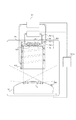
ここで、図1は本発明の冷却装置1を示す概略構成図、冷却装置1は、真空チャンバ内VC内に置かれた光学部材Mを冷却する冷却装置である。真空チャンバVC内は、残留ガス成分と露光光Lとの反応により光学部材Mの表面にコンタミが付着し、反射率が低下することを低減させるため、不図示の真空ポンプによって1×10−6[Pa]程度の真空に維持されている。光学部材Mは、真空チャンバVC内において、不図示の光学部材支持定盤に支持された、不図示の光学部材支持部を介して所定の場所に位置決めされ、反射、屈折及び回折等を利用して光を結像させる。光学部材Mは、例えば、ミラー、レンズ、平行平板ガラス、プリズム及びフレネルゾーンプレート、キノフォーム、バイナリオプティックス、ホログラム等の回折光学素子を含む。本実施形態においては、光学部材としてミラーを例に説明する。冷却装置1は図1によく示されているように、輻射冷却機構(輻射温度調節機構)100と、フード(輻射熱遮断部材)200と、光学部材温度検出部300と、フード温度検出部400と、制御部500とを有する。ここで、フードは略円筒形状をしているが、勿論3角柱、4角柱等の多角柱の形状をしていても構わない。尚、輻射とは、ある部材と別の部材とがある場合に、ある部材から別の部材に輻射熱が伝わり、別の部材からある部材に輻射熱が伝わりと言った2つの部材の間での輻射熱の授受の結果、お互いの他方に伝わる輻射熱の熱量の差分だけ、一方が冷却され、もう一方が加熱されることである。本実施例においては、この輻射熱の授受による加熱や冷却を簡単に表現するために、一方が他方に輻射熱を与える(加熱でも冷却でも)と表現する。
Here, FIG. 1 is a schematic configuration diagram showing a cooling device 1 of the present invention, and the cooling device 1 is a cooling device that cools an optical member M placed in a vacuum chamber VC. In the vacuum chamber VC, a vacuum pump (not shown) uses a vacuum pump (not shown) to reduce the amount of contamination due to the reaction between the residual gas component and the exposure light L on the surface of the optical member M. The vacuum is maintained at about [Pa]. The optical member M is positioned at a predetermined position in the vacuum chamber VC via an optical member support (not shown) supported by an optical member support surface plate (not shown), and utilizes reflection, refraction, diffraction, and the like. To image light. The optical member M includes, for example, a diffractive optical element such as a mirror, a lens, a parallel plate glass, a prism and a Fresnel zone plate, a kinoform, binary optics, and a hologram. In the present embodiment, a mirror will be described as an example of the optical member. As shown in FIG. 1, the cooling device 1 includes a radiation cooling mechanism (radiation temperature adjustment mechanism) 100, a hood (radiation heat blocking member) 200, an optical member
輻射冷却機構100は、光学部材Mの露光面と対向する位置に非接触で配置され、輻射により光学部材Mの露光領域(光学部材の光が照射される領域)Sから熱を吸収する(輻射により相互に与え合う熱の差分だけ光学部材Mから熱を吸収する)。換言すれば、輻射冷却機構100は、露光により高温となった光学部材Mの露光領域のみを輻射により冷却する。輻射冷却機構100は、輻射板101と、循環部102と、パイプ103と、流路104とを有する。ちなみに、ここで言う露光領域とは、露光領域内で最も光の強度が高い位置での光強度の半分以上、もしくは30%以上の光量の光が当たる領域のことである。
The
輻射板101は、不図示の輻射板支持定盤に支持された不図示の輻射板支持部材によって、露光光Lが形成する空間以外に、光学部材Mに対して一定の間隔を有して固定される。輻射板支持定盤及び輻射板支持部材は、一般的に、軽く、剛性が高く、線膨張係数の小さいセラミクスなどから構成される。なお、不図示の光学部材支持定盤と輻射板支持定盤を別体構造とすることで、後述するように、輻射板101に形成された流路104に冷媒が流れることによる輻射板101(及び輻射板支持定盤)の振動が光学部材Mに伝わることを防止することができる。従って、振動によって光学部材Mの表面形状が変形することなく、所望の光学性能を発揮することができる。
The
輻射板101の形状は、露光光が形成する空間以外に、光学部材Mの露光領域Sとの輻射伝熱量を決定する重要なパラメータである形態係数(形態係数が高いほど輻射伝熱量が大きくなる)が最も高く、露光領域Sのみを輻射冷却するように形成されている。また、輻射板101は、後述する循環部102が供給する冷媒が流れるための流路104を有する。流路104は、パイプ103を介して循環部102と接続される。流路104は、輻射板101中の全面に亘って形成され、輻射板101全面に一様に冷媒が流れるように構成される。輻射板101は、冷媒により冷却されて光学部材Mの露光領域Sに対して低温となり温度差を形成する。即ち、輻射板101は、光学部材Mの露光領域Sとの温度差により、光学部材Mの露光領域Sに入射する熱を吸収する。これにより、光学部材Mの露光領域Sのみを輻射冷却することができる。輻射板101は、比較的熱伝導率がよく輻射率の高い材料、例えば、セラミクスの窒化アルミニウム(AlN)かそれ以上に熱伝導率が高い材料、或いは窒化アルミニウムの熱伝導率の90%より大きな熱伝導率を有する材料からなる。
The shape of the
循環部102は、パイプ103と接続し、パイプ103を介して冷媒を流路104に供給及び循環させる。循環部102は、後述する制御部500によって制御され、冷媒の温度を変化させる。冷媒は、輻射板101に形成された流路104を流れることで輻射板101を冷却し、かかる冷媒の温度によって冷却される輻射板101の温度が決定する。なお、本実施形態では、循環部102は、冷媒として水(液体)を供給及び循環させているが、気体等を用いてもよい。ここで、輻射板101の温度の変化に伴って、冷媒を加熱したり冷却したりしても良いが、好ましくは、互いに異なる複数種の温度に調節された冷媒を予め蓄積しておいて、輻射板の目標温度に合わせてそれらの冷媒を混ぜ合わせることによって冷媒を所望の温度にするように調節するのが好ましい。
The circulation unit 102 is connected to the
また、輻射板101が光学部材Mの露光領域S以外を冷却しないための輻射遮蔽部材として、フード200を設ける。フード200は、不図示のフード支持部材により支持され、輻射板101の側面を囲う。また、フード200の内部表面は、表面処理等により輻射率を高めてある(ここでは輻射率を0.8以上、好ましくは0.9以上にしている)。これにより、光学部材Mの露光領域S以外の面から発せられ、フード200の開口部より入射する熱線は、フード200の内部表面に吸収され、輻射板101に到達することはない。フード200は、比較的熱伝導率がよく輻射率の高い材料、例えば、セラミクスの窒化アルミニウム(AlN)か、窒化アルミニウムの熱伝導率の90%より大きな熱伝導率を有する材料からなる。また、ここでは、輻射により冷却する対象を露光領域Sのみとしているので、露光領域S以外を冷却しないように輻射遮蔽部材を設けている。しかしながら、冷却対象は露光領域Sのみに限られている訳ではなく、露光領域Sを含む領域或いは露光領域Sの一部の領域であっても良い。
Further, a
また、本実施例においては、フード200は、輻射板(輻射部材)101の側面全面を覆っており、且つ光学部材と輻射板(輻射部材)101とが対向している(光学部材と輻射板とは平行であっても良いし、お互いの法線が傾いていても構わない)空間の側面の一部の全周を覆う(ある軸を中心に回転対称な形状)ように設けられているが、フードは必ずしも光学部材と輻射板とが対向している空間の全周を覆っている必要は無く、一部が欠けて、全周を覆っていないような構造であっても構わない。
In the present embodiment, the
フード200は、後述する循環部201が供給する流体が流れるための流路202を有する。流路202は、パイプ203を介して循環部201と接続される。流路202は、フード200内の全面に亘って形成され、フード200全面に一様に流体が流れるように構成される。フード200は、流路202を流れる流体により冷却若しくは加熱され、光学部材Mの温度(又は光学部材の目標温度、又は光学部材や光学部材を支持する部材等の目標温度であって、好ましくは22〜24℃、より好ましくは23.5〜24.5℃の範囲内)と等しい値に保たれる。これにより、光学部材Mとフード200は輻射伝熱をしない、つまり、光学部材Mはフード200自身により加熱もしくは冷却されることはない。従って、冷却機構1は、光学部材Mの露光領域Sのみを、輻射板101からの輻射により冷却することができる。
The
ここで、フード200の温度を光学部材の目標温度と同じになるように温度調節する場合は、光学部材が目標温度(フード200の温度と同じ)とずれている場合には、フードと光学部材との間にも若干の熱交換が生じることとなる。但し、その場合でも、光学部材Mとフードとの温度差が小さい(2度以内、より好ましくは0.5度以内)ため、光学部材Mを冷却する(光学部材Mと熱交換をしている)のは、実質的に輻射板101のみである。また、フード200の温度を光学部材や光学部材の支持部材等の目標温度と一致させる場合も、光学部材Mの温度とフード200の温度との間に若干の温度差があったとしてもその温度差はわずか(2度以内、より好ましくは0.5度以内)であり、光学部材Mとフード200との間でやりとりされる熱量はごくわずかであるため、光学部材Mを冷却する(光学部材Mと熱交換をしている)のは、実質的に輻射板101のみである。
Here, when the temperature of the
循環部201は、パイプ203と接続し、パイプ203を介して冷媒を流路202に供給及び循環させる。循環部201は、後述する制御部500に制御され、流体の温度を変化させる。流体は、流路202を流れることでフード200を冷却若しくは加熱し、かかる流体の温度によってフード200の温度が決定する。なお、本実施形態では、循環部201は、冷媒として水(液体)を供給及び循環させているが、気体等を用いてもよい。
The
光学部材温度検出部300は、光学部材Mの露光光Lが照射される照射領域以外に取り付けられ、光学部材Mの温度を検出する。また、光学部材温度検出部300は、検出した光学部材Mの温度を後述する制御部500に送信する。光学部材温度検出部300は、例えば、熱電対、抵抗温度センサー、赤外線温度センサーなどの温度センサーから構成される。なお、本実施形態では、光学部材温度検出部300を光学部材Mに取り付けている(接触させている)が、光学部材Mと非接触に光学部材温度検出部300を構成し、光学部材Mの温度を検出してもよい。光学部材Mに対して非接触の光学部材温度検出部300を設ける場合は、温度検出を行う部分は、露光領域(露光光の照射領域)S内であっても構わないし、露光領域外であっても良い。
The optical member
また、光学部材Mに温度分布がある場合を考えると、光学部材温度検出部300の取り付け場所によっては、光学部材温度検出部300で検出される温度と光学部材Mの露光領域Sの平均温度との差が大きな場合がある。このような場合、光学部材温度検出部300で検出される温度から、光学部材Mの露光領域Sの温度(平均温度等)を推測してもよいし、光学部材温度検出部300で検出される温度と図示しない温度計等(温度検出手段)により検出したチャンバVC内の温度とにより、光学部材Mの露光領域Sの温度を推測し、その推測された温度に従って冷却するようにしてもよい。
Considering the case where the optical member M has a temperature distribution, the temperature detected by the optical member
フード温度検出部400は、フード200の表面に接触して温度を計測する。フード温度検出部400は、例えば、熱電対、抵抗温度センサー、赤外線温度センサーなどの温度センサーから構成される。また、フード温度検出部400は、検出した光学部材Mの温度を後述する制御部500に送信する。なお、本実施形態では、フード温度検出部400をフード200に取り付けている(接触させている)が、フード200と非接触にフード温度検出部400を構成し、フード200の温度を検出してもよい。また、本実施形態では、フード温度検出部400をフード200の外側に接触させた状態で配置し、フード200の外側の温度を測定しているが、フード温度検出部をフード200の内側に接触させて配置しても良いし、またフード温度検出部によりフード200の内側の所定の領域(点)の温度を測定するように構成しても良い。
The
制御部500は、光学部材温度検出部300で検出される光学部材Mの露光面温度が所定の値になるように、輻射冷却機構100を制御する。より詳細には、循環部102が輻射板101(の流路104)に供給及び循環させる冷媒の温度を変化させることで輻射板101の温度を制御する。かかる制御によって、輻射板101が光学部材Mの露光領域Sから吸収する熱量を調節し、光学部材Mの温度を所定の値にする。換言すれば、制御部500は、光学部材Mの露光領域Sの温度を一定に保つ機能を有する。ここで、制御部500は、光学部材温度検出部300や、露光領域S或いは光学部材Mに入射する光の光量や、その分布等に基づいて、輻射板101Aの温度、ペルチェ素子に印加する印加電圧を決定しても良い。例えば、露光装置の投影光学系に本実施例の輻射冷却機構を組み入れた場合、投影光学系内の光学素子(ミラー、レンズ、回折光学素子等)の温度検出結果や、露光スケジュール(光源から発する光の光量、パルス数、レチクルのパターン等)や、その光学素子における光量分布に従って(勿論すべてを考慮しても良い)、輻射冷却機構を制御する(輻射板の温度を制御する)のが好ましい。
The
また、制御部500は、フード温度検出部400で検出されるフード200の温度が、光学部材温度検出部300で検出される光学部材Mの温度(又は光学部材の目標温度、又は光学部材や光学部材を支持する部材等の目標温度)と実質的に等しくなる(誤差は2度以内、より好ましくは0.5度以内)ように、循環部201がフード200(の流路202)に供給及び循環させる流体の温度を変化させる。かかる制御により、フード200の温度は光学部材Mの温度と等しくなるため、フード200は光学部材Mを加熱もしくは冷却することはない。
Further, the
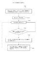
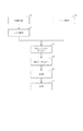
ここで、図2を用いて冷却装置1を用いた光学部材Mの冷却方法2000について説明する。図2は、真空雰囲気下に置かれた光学部材Mを冷却する冷却方法2000を説明するためのフローチャートである。 Here, a cooling method 2000 of the optical member M using the cooling device 1 will be described with reference to FIG. FIG. 2 is a flowchart illustrating a cooling method 2000 for cooling the optical member M placed in a vacuum atmosphere.
但し、フード200は、制御部500によって光学部材Mと等しい温度を有しており、光学部材Mを加熱若しくは冷却することはない。
However, the
まず、光学部材温度検出部300は露光光Lが照射されていない状態(初期状態)の光学部材Mの温度を検出し、検出した初期状態の温度を制御部500に送信する。制御部500は、受信した光学部材Mの初期状態の温度を所定の値として記憶する(ステップ2001)。但し、初期状態では、光学部材Mは表面形状に変化がないものとする。次に、露光光Lが照射されると(ステップ2002)、光学部材温度検出部300は光学部材Mの温度を検出し(ステップ2003)、光学部材温度検出部300が検出した光学部材Mの温度と所定の値が等しいかどうか判断する(ステップ2004)。検出した光学部材Mの温度が所定の値と等しい場合、光学部材Mに露光光Lが照射している間は、ステップ2004以下を繰り返す。検出した光学部材Mの温度が所定の値と異なる場合、制御部500は、光学部材Mの温度が所定の値となるために必要な輻射板101の温度を算出する。(ステップ2005)。制御部500は、算出した輻射板101の温度に基づいて、循環部102が供給及び循環させる冷媒の温度を調節し、輻射板101を冷却する(ステップ2006)。即ち、ステップ2006は、光学部材Mの露光領域Sと輻射板101との間に温度差を形成する。従って、輻射により光学部材Mの熱を輻射板101が吸収し、光学部材Mの温度を所定の値にすることができる。以下、光学部材Mに露光光Lが照射されている間(即ち、露光中)は、ステップ2004以下を繰り返す。
First, the optical
従って、冷却装置1及び冷却方法2000によれば、真空環境下に置かれた、熱伝導性が低い材質で構成された光学部材Mであっても、露光により入熱する露光領域Sのみを輻射により冷却することによって、効率良く入熱を吸収することができる。これにより、光学部材Mに接触することなく、光学部材Mの温度を一定にすることができ、結像性能の劣化となる光学部材Mの熱膨張による変形を低減させて、所望の光学性能を実現することができる。 Therefore, according to the cooling device 1 and the cooling method 2000, even the optical member M placed in a vacuum environment and made of a material having low thermal conductivity radiates only the exposure region S that receives heat by exposure. By cooling, heat input can be efficiently absorbed. Thereby, the temperature of the optical member M can be kept constant without contacting the optical member M, and the deformation due to the thermal expansion of the optical member M, which deteriorates the imaging performance, can be reduced, so that the desired optical performance can be obtained. Can be realized.
ここで、図2のフローチャートのステップ2001において、必ずしも「光学部材の初期温度」を「所定の値」とする必要はなく、光学部材Mが設計値通りの形状になる温度を「所定の値」とすれば良い。例えば、光学部材が23[℃]であれば、設計値通りの形状となることが分かっていれば、「所定の値」は23[℃]とすれば良い。勿論、この値は装置によって異なるが、20[℃]から25[℃]の間、好ましくは22[℃]から24[℃]の間に設定するのが良い。
Here, in
次に、図3を参照して、冷却装置1の変形例である冷却装置1Aについて説明する。冷却装置1Aは、冷却装置1と比較して輻射冷却機構100A及び制御部500Aについて異なる。その他詳細に述べない部分については、図1の冷却装置1と同様である。
Next, a cooling device 1A which is a modification of the cooling device 1 will be described with reference to FIG. The cooling device 1A differs from the cooling device 1 in the
冷却装置1Aは、冷却装置1と同様、図示しない真空ポンプによって1×10⁻⁶[Pa]程度の真空に維持された真空チャンバVC内に置かれた光学部材Mを冷却する冷却装置である。本実施形態においては、光学部材Mとしてミラーを例に説明する。冷却装置1Aは、図3によく示されるように、輻射冷却機構100Aと、フード200と、光学部材温度検出部300と、フード温度検出部400と、制御部500Aとを有する。
The cooling device 1A, like the cooling device 1, is a cooling device that cools the optical member M placed in a vacuum chamber VC maintained at a vacuum of about 1 × 10 −6 [Pa] by a vacuum pump (not shown). In the present embodiment, a mirror will be described as an example of the optical member M. As shown in FIG. 3, the cooling device 1A includes a
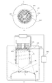
輻射冷却機構100Aは、光学部材Mの露光面と対向する位置に非接触で配置され、光学部材Mに対して輻射により光学部材Mの露光領域Sから熱を吸収する。換言すれば、輻射冷却機構100Aは、露光により高温となった光学部材Mの露光領域のみを輻射により冷却する。輻射冷却機構100Aは、輻射板101Aと、循環部102Aと、パイプ103Aと、ペルチェ素子105と、放熱ブロック106と、流路107とを有する。(図1の説明でも記載したが、ここでは露光領域S、つまり光が照射される領域を冷却対象としているため、露光領域S以外を極力冷却しないようにしている。しかしながら、露光領域Sだけが冷却対象ではない場合、つまり露光領域Sを含む領域を冷却する場合や露光領域Sの一部を冷却する場合も考えられるため、必ずしも露光領域Sのみを輻射により冷却するように輻射冷却機構100Aを構成している訳ではない。)
The
輻射板101Aは、不図示の輻射板支持定盤に支持された不図示の輻射板支持部材によって、露光光Lが形成する空間以外に、光学部材Mに対して一定の間隔を有して固定される。輻射板101Aは、後述するペルチェ素子105が接合され、ペルチェ素子105のペルチェ効果により冷却されて光学部材Mの露光領域Sに対して低温となり温度差を形成する。即ち、輻射板101Aは、光学部材Mの露光領域Sとの温度差により、光学部材Mの露光領域Sの熱を吸収する。輻射板101Aとペルチェ素子105との接合は、放出ガス量が低く、且つ、熱伝導性のよい蒸着、半田等の金属のメタライズによって行う。輻射板101Aとペルチェ素子105との接合を金属によって行うことで、接着剤を使用する場合に発生してしまう放出ガスをなくし、光学部材Mの表面にコンタミが付着することを防止することができる。ここで、接合する際には勿論樹脂材料等から成る接着剤を用いても構わない。但し、脱ガスが少ない接着剤であることが好ましい。
The
輻射板101Aは、比較的熱伝導性がよく輻射率の高い材料、例えば、セラミクスの窒化アルミニウム(AlN)かそれ以上に熱伝導率が高い材料、悪くても窒化アルミニウムの熱伝導率の90%以上の熱伝導率を有する材料からなる。輻射板101Aの形状は、光学部材Mの露光領域Sとの輻射伝熱量を決定する重要なパラメータである形態係数が最も高く、露光領域Sのみを輻射冷却するように形成されている。これにより、光学部材Mの露光領域Sのみを輻射にて冷却することができる。
The radiating
ペルチェ素子105は、例えば、p型半導体及びn型半導体を熱的に並列に配置して構成される。ペルチェ素子105は、後述する制御部500Aに制御され、輻射板101Aと接合してペルチェ効果により輻射板101Aを冷却する。「ペルチェ効果」とは、2種類の導体や半導体の接点に電流を流すと電導率の違いから熱の移動が起こるという現象である。本実施形態では、ペルチェ素子105は、p型半導体及びn型半導体で構成しているので、p型半導体からn型半導体の領域では電子が流れにくいため熱を吸収する吸熱面108を形成し、n型半導体からp型半導体の領域では電子が流れやすいため熱を放出する放熱面109を形成する。従って、ペルチェ素子105の放熱面109を輻射板101Aと接合することで、輻射板101Aから熱を吸収して冷却することができる。また、ペルチェ素子105が吸収できる熱量は、印加電圧によって調節することができる。ペルチェ素子105は、応答性が高いために高精度に輻射板101Aの温度を制御して、光学部材Mの温度を所定の値にすることができる。ペルチェ素子105の放熱面109には、放熱ブロック106が接合されている。
The
放熱ブロック106は、ペルチェ素子105の放熱面109に金属によって接合されている。放熱ブロック106とペルチェ素子105との接合に金属を用いるのも、上述したように、放出ガス量を抑え、熱伝導性を高めるためである。放熱ブロック106は、後述する循環部102Aが供給する冷媒が流れるための流路107を有する。流路107は、パイプ103Aを介して循環部102Aと接続される。流路107は、放熱ブロック106中の全面に亘って形成され、放熱ブロック106全面に一様に冷媒が流れるように構成される。放熱ブロック106は、冷媒により冷却されてペルチェ素子105の放熱面109から排熱される輻射板101Aを介して吸収した光学部材Mの熱を回収する。放熱ブロック106は、例えば、セラミクスの窒化アルミニウム(AlN)からなる。
The
循環部102Aは、パイプ103Aと接続し、パイプ103Aを介して冷媒を放熱ブロック106の流路107に供給及び循環させる。循環部102Aが流路107に供給及び循環させる冷媒は、放熱ブロック106からの排熱を回収し、放熱ブロックの温度を略一定(光学部材の目標温度±1度以内、より好ましくは0.5度以内、つまり温度変化を2度以内、より好ましくは1度以内に抑えることが望ましい)に保つためである。従って、冷媒の温度は、可変とする必要がなく、また、極端に低温とする必要もない。例えば、光学部材Mの温度を23℃(所定の値)に保ちたい場合、冷媒の温度は23℃で十分である。即ち、循環部102Aは、一定の温度(例えば、光学部材Mの保ちたい温度)の冷媒を供給及び循環させればよい。これにより、引き回し途中でパイプ103Aが、温度変化することで光学部材が位置ずれを起こし、光学部材の光学性能を劣化させてしまう部材、例えば、レーザー干渉計固定部材、光学部材支持部材の冷却を防止することができる。
The circulation unit 102A is connected to the
ここで、流路107に流す冷媒は、フード200内に配置されている流路202や、流路202に接続されているパイプ203に流す冷媒と同じ温度の冷媒を用いても良い。光学部材や光学部材を支持する支持部材の目標温度(例えば23℃、22〜24℃の範囲内であることが望ましい。)と、フード200内の流路202に流す冷媒の温度と、放熱ブロック内の流路107に流す冷媒の温度とを同じにすることが望ましい。さらには、ペルチェ素子を挟んで光学部材と反対側に配置されている放熱ブロック内を流れる冷媒と、フード内を流れる冷媒とが、同じ循環部から供給される冷媒、すなわち同じ温度の同じ冷媒であれば、循環部(冷媒を流す装置)を複数設ける必要が無くなるため望ましい。ここでは、誤差0.5度以内、好ましくは0.2度以内であれば、実質的に同じ温度と見なす。
Here, as the refrigerant flowing through the
制御部500Aは、温度検出部300で検出される光学部材Mの露光領域Sの温度が所定の値になるように、輻射冷却機構100Aを制御する。制御部500Aは、より詳細には、ペルチェ素子105に印加する印加電圧を変化させることで輻射板101Aの温度を制御する。即ち、制御部500Aは、輻射板101Aが吸収しなければならない熱量を算出し、かかる熱量から輻射板101Aの温度を決定する。更に、制御部500Aは、決定した輻射板101Aの温度に基づいて、ペルチェ素子105に印加する印加電圧を調節する。かかる制御によって、輻射板101Aが光学部材Mの露光領域Sから吸収する熱量が調節され、光学部材Mの露光領域S温度が所定の値となる。換言すれば、制御部500Aは、光学部材Mの露光領域Sの温度を一定に保つ機能を有する。ここで、制御部500Aは、露光領域S或いは光学部材Mに入射する光の光量や、その分布等に基づいて、輻射板101Aの温度、ペルチェ素子に印加する印加電圧を決定しても良い。例えば、露光装置の投影光学系に本実施例の輻射冷却機構を組み入れた場合、投影光学系内の光学素子(ミラー、レンズ、回折光学素子等)の温度検出結果や、露光スケジュール(光源から発する光の光量、パルス数、レチクルのパターン等)や、その光学素子における光量分布に従って(勿論すべてを考慮しても良い)、輻射冷却機構を制御する(輻射板の温度を制御する)のが好ましい。
The
また、制御部500Aは、フード温度検出部400で検出されるフード200の温度が、光学部材温度検出部300で検出される光学部材Mの温度と等しくなるように、循環部201がフード200(の流路202)に供給及び循環させる流体の温度を変化させる。かかる制御により、フード200の温度は光学部材Mの温度と等しくなるため、フード200は光学部材Mを加熱もしくは冷却することはない。
The
冷却装置1Aによれば、輻射冷却機構100Aに温度の応答性に優れたペルチェ素子105を用いることで、輻射板101Aの温度制御が向上し、光学部材Mの露光領域Sの温度を高精度に安定させることができる。従って、冷却装置1Aによれば、真空環境下に置かれた、熱伝導性が低い材質で構成された光学部材Mであっても、露光による入熱が行われる露光領域Sを輻射により冷却することによって、効率良く入熱を吸収することができる。これにより、光学部材Mに接触することなく、光学部材Mの温度を一定にすることができ、結像性能の劣化となる光学部材Mの熱膨張による変形を低減させて、所望の光学性能を実現することができる。なお、冷却装置1Aを用いた光学部材Mの冷却方法については、図2を参照して説明した冷却方法2000と同様であるので、ここでは詳しい説明は省略する。
According to the cooling device 1A, the temperature control of the
図4は、輻射板101Aの形状が、光学部材Mの露光領域Sの形状と異なる等の理由により、輻射板101Aが光学部材Mの露光領域S以外を輻射冷却してしまう場合を説明する図である。図4には、代表例として冷却機構1Aと、光学部材Mと、真空チャンバVCを示している。この場合、フード200の光学部材M側開口部に輻射遮蔽絞り600を配置する。輻射遮蔽絞り600の形状は、輻射板101Aが、光学部材Mの露光領域Sのみを冷却するように形成されている。つまり、輻射遮蔽絞り600は、フード200の光学部材M側開口部に固定してあり、露光領域S以外から発せられる熱線を遮蔽する役割を果たす。これにより、輻射板101Aは、光学部材Mの露光領域Sのみを輻射にて冷却することができる。また、輻射遮蔽絞り600は、フード200に固定されているため、フード200からの熱伝達により、光学部材Mと等しい温度に温調される。これにより、輻射遮蔽絞り600は光学部材Mの露光面Sを加熱若しくは冷却しない。輻射遮蔽絞り600の材質としては、熱伝導率が高い材質、例えばアルミや銅などが好ましい。
FIG. 4 is a diagram illustrating a case where the
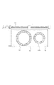
更に、露光光のNAに応じて、輻射遮蔽絞り600の形状を変化させる機構を設けると良い。図5に、輻射遮蔽絞り600の形状を変化させる機構の一例を示す。701は移動板であり、その表面側には、輻射遮蔽絞り600及び600aを保持している。一方、裏面側には必要な露光領域の形状に応じて、輻射遮蔽絞り600を変更できるように後述するスライドガイド702のテーブルが取り付けられている。ここで、移動板701の材質は前出の輻射遮蔽絞り600と同様の機能を有するために、輻射率及び熱伝導性の高い材質が好ましい。702はスライドガイドであり、ガイドレールは不図示の支持板に保持されている。703はボールねじである。ボールねじ703は移動板701に取り付けられている。移動板701は、ボールねじの片端を回転することにより、矢視方向に移動する。以上の構成により、必要時には輻射遮蔽絞り600の形状を可変とし、輻射板101Aは、光学部材Mの露光領域Sのみを輻射にて冷却することができる。また、図5のような機構がスペース上配置できない場合は、輻射遮蔽絞り600の開口部の形状を調整自在とし、露光領域Sの形状に合わせて調整するものとする。これにより、輻射板101Aは、光学部材Mの露光領域Sのみを輻射にて冷却することができる。また、図4では代表例として冷却装置1Aを使用した場合の説明を行ったが、冷却装置1を使用しても同様の効果を発揮することは言うまでもない。また、この輻射遮蔽絞りは、虹彩絞りのように開口径が可変な開口絞りをフードの開口部に設けるような構成としても構わない。また、輻射遮蔽絞りの位置は、必ずしも、フードの開口部に設ける必要は無く、フードの真中近辺に設けても良い、好ましくは、輻射板とフードの開口部との真中よりもフードの開口部側に設けるのが良い。
Further, a mechanism for changing the shape of the
図6は、光学部材Mの露光領域Sが、露光領域Sの中心点を中心とした同心円状に変化する不均一な温度分布を有している場合を説明する図である。図6に代表例として、冷却装置1Aと、光学部材Mと、真空チャンバVCとを示す。図6(a)は、冷却装置1Aと光学部材Mを上面から見た上面図、図6(b)は冷却装置1Aと、光学部材Mと、真空チャンバVCを側面から見た側面図である。但し、図6(a)において、放熱ブロック106、循環部102A、パイプ103A、循環部201、パイプ203、制御部500、真空チャンバVCは省略してある。
FIG. 6 is a diagram illustrating a case where the exposure region S of the optical member M has a non-uniform temperature distribution that changes concentrically around the center point of the exposure region S. FIG. 6 shows a cooling device 1A, an optical member M, and a vacuum chamber VC as typical examples. 6A is a top view of the cooling device 1A and the optical member M as viewed from above, and FIG. 6B is a side view of the cooling device 1A, the optical member M, and the vacuum chamber VC as viewed from the side. . However, in FIG. 6A, the
700は、光学部材Mの露光面温度分布を非接触に検出する温度分布検出部である。温度分布検出部700は、真空チャンバVC内に不図示の温度分布検出器支持部により、光学部材Mの露光面全面の温度分布が測定できる位置に支持されている。温度分布検出部700には、光学部材M露光面上の多点を測定することができる多点式放射温度計やサーモグラフィなどが適している。温度分布検出部700で検出される値は、後述する制御部500Aに送信される。但し、一般に非接触式の温度計の計測精度は接触式のそれと比較して劣るため、制御部500Aは、温度分布検出部の測定結果は光学部材温度検出部300で検出される値に修正する。これにより、光学部材Mの露光面の温度分布を精度良く知ることができる。
図6に示すように、輻射板101Aには、複数のペルチェ素子105a乃至105dを同心円状に接合している。複数のペルチェ素子105a乃至105dは、制御部500Aによって個別に制御され、それぞれ輻射板101Aを冷却する。これにより、輻射板101Aは、複数のペルチェ素子105a乃至105dの各々の温度に対応した温度分布を有することができる。この場合、輻射板101Aの材質としては、比較的輻射率が高く、熱伝導率が低いものが好ましい。
As shown in FIG. 6, a plurality of
制御部500Aは、温度分布検出部700で検出された光学部材M露光面の温度分布を、光学部材温度検出部300で検出した値に修正する。これにより、光学部材Mの露光面温度分布をより正確に知ることができる。
The
また、制御部500Aは、温度分布検出部700で検出される光学部材Mの温度分布が均一且つ所定の値になるように、輻射冷却機構100Aを制御する。制御部500Aは、より詳細には、複数のペルチェ素子105に印加する印加電圧をそれぞれ変化させることで輻射板101Aの温度分布を制御する。即ち、制御部500Aは、光学部材Mの露光面温度分布から輻射板101Aが吸収しなければならない熱量を算出し、かかる熱量から輻射板101Aの温度分布を決定する。例えば、露光領域Sが中心部が最も高温で、半径方向に進むに従って低温になるような温度分布を有している場合、ペルチェ素子105aを最も低温にし、次いで105b、105c、105dの順に低温にすれば良い。更に、制御部500Aは、決定した輻射板101Aの温度分布に基づいて、複数のペルチェ素子105にそれぞれ印加する印加電圧を調節する。かかる制御によって、輻射板101Aが光学部材Mから吸収する熱量が調節され、光学部材Mの温度分布が均一且つ所定の値となる。換言すれば、制御部500Aは、光学部材Mの温度分布を均一且つ一定に保つ機能を有する。また、図6では代表例として冷却装置1Aを使用した場合の説明を行ったが、冷却装置1を使用しても、輻射板101に温度分布を生じさせることにより、同様の効果を発揮することは言うまでもない。
The
従って、光学部材Mの露光領域Sが加熱され、不均一な温度分布が生じている場合でも、冷却装置1若しくは1Aによって、光学部材Mの露光領域Sの温度を均一且つ一定に保つことが可能である。また、図6にでは、光学部材Mの露光領域Sが、露光領域Sの中心点を中心とした同心円状に変化する不均一な温度分布を有している場合について説明したが、露光領域Sの温度が別の分布形状を有している場合は、必要に応じて複数のペルチェ素子105の配置、形状、個数を選択すれば良いことは言うまでもない。
Therefore, even when the exposure region S of the optical member M is heated and an uneven temperature distribution occurs, the temperature of the exposure region S of the optical member M can be kept uniform and constant by the cooling device 1 or 1A. It is. FIG. 6 illustrates the case where the exposure region S of the optical member M has a non-uniform temperature distribution that changes concentrically around the center point of the exposure region S. Needless to say, if the temperature has another distribution shape, the arrangement, shape, and number of the plurality of
図1乃至図6では、冷却装置1及び1Aは、輻射冷却機構100及び100Aが光学部材Mの露光面と対向するように配置されている。しかし、露光光の入射角が小さい若しくはスペース上の理由等で、輻射冷却装置100及び100Aを光学部材Mの露光面と対向する位置に配置できない場合は、斜方向から光学部材Mの露光領域Sを輻射冷却しても良い。
1 to 6, the cooling devices 1 and 1A are arranged such that the
図7は、冷却装置1Aを用いて光学部材Mの露光領域Sのみを、斜方向から冷却する場合の実施例である。図7(a)においては、光学部材M、輻射板101A、フード200、輻射遮蔽絞り600以外は省略してある。図7(a)は、冷却装置1A及び光学部材Mを上面から見た上面図、図7(b)は冷却装置1A及び光学部材MのA−A断面図である。図7(a)及び図7(b)に示すように、冷却装置1Aは斜方向から光学部材Mの露光領域Sのみを輻射冷却することが可能である。
FIG. 7 shows an embodiment in which only the exposure region S of the optical member M is cooled from an oblique direction using the cooling device 1A. In FIG. 7A, components other than the optical member M, the
しかし、斜方向から冷却した場合、露光領域Sを局所的に見ると、輻射板101Aとの距離に偏りが生じている。そのため、輻射板101Aと露光領域Sとの形態係数にも偏りが生じてしまうため、露光領域Sを均一に冷却することができない。従って、斜方向より光学部材Mの露光領域Sを輻射冷却する際には、図7(a)及び図7(b)に示すように露光領域Sの中心点を中心にした円周上に、冷却装置1Aを複数個等配する。これにより、露光領域Sに対する輻射冷却量の偏りを打ち消しあうことができる。従って、光学部材Mの露光領域Sを均一に輻射冷却することができる。但し、図7(a)及び図7(b)では4つの冷却装置1Aを光学部材Mの周囲に等配しているが、露光光を遮蔽することなく、光学部材Mの露光領域Sを均一に冷却できるならば個数は問わないことは言うまでもない。また、図7では、冷却装置1Aを使用した実施例を示しているが、冷却装置1を使用しても同様の効果を得ることができる。
However, when cooling is performed in an oblique direction, when the exposure region S is locally viewed, the distance from the
また、図7において、冷却装置を1つとしても良い。その場合は、輻射板に温度傾斜(温度分布)を設ける、つまり輻射板の互いに異なる領域の温度が異なるようにする。具体的には、輻射板の光学部材(ミラー等)までの距離が最も近い領域の温度が、輻射板の光学部材までの距離が最も遠い領域の温度よりも高くなるように制御する。この場合、輻射板を光学部材からの距離に従って(光学部材の中心点における接線方向と平行に)複数の領域に分割し、この分割された複数の領域それぞれに対して個別に温度制御を行えるようにしても構わないし、この複数の領域の間の少なくとも1つにおいて温度差が生じるような構成としても良い。また、輻射板の材料に熱伝導率が高くない材料を用いた上で、輻射板の光学部材までの距離が最も遠い領域近傍(輻射板の光学部材までの距離が最も遠い領域と最も近い領域との中間位置よりも、最も遠い領域に近い側、より好ましくは、輻射板の光学部材までの距離が最も遠い領域からの距離が、最も遠い領域と最も近い領域との間の距離の1/4以下の領域)において、ペルチェ素子(すなわち輻射板を冷却する部材)と接触させるようにすれば、自ずと輻射板に温度分布ができる。また、輻射板内において、輻射板とペルチェ素子とを接触させた位置と反対の位置に別のペルチェ素子を接触させて、輻射板の温度分布を形成し続けても構わない。 Further, in FIG. 7, one cooling device may be provided. In that case, the radiation plate is provided with a temperature gradient (temperature distribution), that is, the temperatures of different regions of the radiation plate are made different. Specifically, control is performed such that the temperature of the region where the distance to the optical member (mirror or the like) of the radiation plate is closest is higher than the temperature of the region where the distance to the optical member of the radiation plate is farthest. In this case, the radiation plate is divided into a plurality of regions according to the distance from the optical member (parallel to the tangential direction at the center point of the optical member), and temperature control can be individually performed on each of the divided regions. Alternatively, the temperature difference may be generated in at least one of the plurality of regions. In addition, after using a material having a low thermal conductivity for the radiation plate, the vicinity of the region where the distance to the optical member of the radiation plate is the longest (the region where the distance to the optical member of the radiation plate is the longest and the region that is the shortest) The distance from the region farthest to the optical member, more preferably, the distance from the region farthest to the optical member of the radiation plate is 1/1/1 of the distance between the farthest region and the closest region. If the radiating plate is brought into contact with the Peltier element (that is, a member that cools the radiating plate) in the region (4 or less), the radiating plate naturally has a temperature distribution. In the radiation plate, another Peltier device may be brought into contact with a position opposite to the position where the radiation plate and the Peltier device are brought into contact, and the temperature distribution of the radiation plate may be continuously formed.
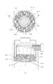
図8は、冷却装置1Aの更なる実施例である。特に説明しない部材に関しては図1に示す実施例と同様である。この図8において、輻射板101Aの形状は、八の字型(ハの字型)の断面を有した回転体であり、露光領域Sの中心部分の法線方向に対して、露光領域Sと向かい合う方向に傾けて設けられている。言い換えると、露光領域Sを覆うように設けられた半球体もしくは円錐の側面部から、露光領域Sに入射する光の光路と干渉する部分を除去したような形状になっている。
FIG. 8 is a further embodiment of the cooling device 1A. Members not particularly described are the same as those in the embodiment shown in FIG. In FIG. 8, the
但し、この図8の実施例における輻射板の形状は、八の字型の断面を有する回転体であっても構わないが、完全な回転体である必要はなく、回転体の一部(例えば円錐台の側面部等)であっても構わない(すなわち上述したような円錐の側面の一部や球体の一部等)。また、輻射板の形状が回転体もしくは回転体の一部ではなく、三角錐、四角錐等(多角錐)の角錐の側面の一部のような形状をしていても構わない。勿論、冷却効率(温度調節効率)が許す場合は、輻射板の形状を円柱の側面、角柱の側面のような形状にしても構わない。 However, the shape of the radiation plate in the embodiment of FIG. 8 may be a rotating body having an eight-shaped cross section, but it is not necessary to be a complete rotating body, and a part of the rotating body (for example, It may be a side part of a truncated cone or the like (that is, a part of a side surface of a cone or a part of a sphere as described above). Further, the shape of the radiation plate may not be a rotator or a part of the rotator but may be a shape like a part of a side surface of a pyramid such as a triangular pyramid or a quadrangular pyramid (polygonal pyramid). Of course, if cooling efficiency (temperature control efficiency) allows, the shape of the radiation plate may be shaped like a side surface of a cylinder or a side surface of a prism.
また、輻射板の断面形状は露光領域Sに対して凹を向けた曲率を有していることが好ましい。さらに、この凹面の曲率半径を輻射板と露光領域Sの中心部との距離と同じか、もしくは輻射板と露光領域Sの中心部との距離より長くするのが良い。 Further, it is preferable that the cross-sectional shape of the radiation plate has a curvature that is concave toward the exposure region S. Further, it is preferable that the radius of curvature of the concave surface is equal to the distance between the radiation plate and the center of the exposure region S or longer than the distance between the radiation plate and the center of the exposure region S.
上記のような輻射板101Aと、輻射遮蔽絞り600とを組み合わせることによって、輻射板101Aは露光光Lを遮蔽することなく、光学部材Mの露光領域Sを効率良く冷却することが可能となる。更に、輻射板101Aは、露光領域Sの中心点を中心にした円周上に略均一に配置されているため、より均一に露光領域Sを冷却することが可能である。また、本実施例によると、フード200は1個しか必要ではないため、図7で説明した実施例に対して、コストダウンや省スペース化を図ることが可能である。但し、必要に応じて、輻射板101Aの裏面に、複数のペルチェ素子105を接合しても良い。また、図8では、例として冷却装置1Aを示したが、冷却装置1を使用しても同様の効果を得ることができることは言うまでもない。
By combining the
また、必要に応じて、図9に示すように一つのフード内に複数の輻射板101Aa、101Ab、101Ac、101Adを配置しても良い。複数の輻射板101Aa〜101Abの形状は、それぞれ露光光Lが形成する空間以外に、光学部材Mの露光領域Sとの輻射形態係数が最も大きくなるように形成されている。複数の輻射板101Aa〜Adの裏面には、それぞれペルチェ素子105a、105b、105c、105dが接合してあり、複数の輻射板101Aa〜Adの温度を、個別に制御することが可能である。但し、図9では、4枚の輻射板101Aを露光領域Sの周囲に等配しているが、露光光を遮蔽することなく、光学部材Mの露光領域Sを均一に冷却できるならば、必要に応じて複数の輻射板101Aa〜101Abの個数、形状、配置を選択しても良い。また、図9では、例として冷却装置1Aを示したが、冷却装置1を使用しても同様の効果を得ることができるし、輻射板の形状等に関しては図8と同様に様々なパターンが考えられることは言うまでもない。
If necessary, a plurality of radiation plates 101Aa, 101Ab, 101Ac, and 101Ad may be arranged in one hood as shown in FIG. The shapes of the radiation plates 101Aa to 101Ab are formed so that the radiation form factor with the exposure region S of the optical member M becomes the largest, in addition to the space formed by the exposure light
次に、図10を用いて遮蔽構造(絞り装置)100Bについて説明する。この遮蔽構造は露光装置の投影光学系に適用しても良いし、露光装置の照明光学系やその他周知のいかなる光学系に適用してもよい。なお、各図において同一の参照番号を付した部材は同一部材を示し、重複した符号の説明は省略する。 Next, the shielding structure (aperture device) 100B will be described with reference to FIG. This shielding structure may be applied to the projection optical system of the exposure apparatus, or may be applied to the illumination optical system of the exposure apparatus or any other known optical system. In the drawings, members denoted by the same reference numerals indicate the same members, and the description of the same reference numerals will be omitted.
本図において、110、115はミラーであり、反射を利用して光を結像させる。ミラー110、115の反射面には光を反射させる多層膜が施されており、かかる多層膜により光を強めあう作用を奏する。ミラー110、115に適用可能な多層膜は、例えば、モリブデン(Mo)層とシリコン(Si)層を交互に積層したMo/Si多層膜、又は、Mo層とベリリウム(Be)層を交互に積層したMo/Be多層膜などが考えられる。但し、本発明の多層膜は、上記した材料に限定されず、これと同様の作用及び効果を有する多層膜の使用を妨げるものではない。
In the figure, mirrors 110 and 115 form an image of light using reflection. The reflecting surfaces of the
120、125はミラー110、115を支持する支持部材であり、ミラーに変形を与えないような構造となっている。支持部材は120、125は熱変動に伴って変形しないように低熱膨張材、例えば、インバやスーパインバを使用することが好ましい。また、ミラー変形を与えない構成の一例として、ミラーをキネマチック支持する方法が考えられる。
130、135は支持部材120、125を保持しているベースプレートである。これらはいずれも不図示の鏡筒に支持されている。前記支持部材120、125と同様にこれらの材質も熱変動に伴って変形しないように低熱膨張材、例えば、インバやスーパインバを使用することが好ましい。また、これらの構造も支持部材120、125を変形させないように十分な剛性を有する構造であることが望ましい。
130 and 135 are base plates holding the supporting
Lはミラー110に入射する露光光である。露光光は不図示の光源から出射され、複数のミラーを反射して本図のミラー110に入射している。この露光光はミラー110において反射され、ミラー115に入射している。
L is exposure light incident on the
140、145は遮蔽絞りである。これらは不図示の構造に支持されている。遮蔽絞り140,145は露光光Lの光束を制限するとともに、他の物体から放射される熱を遮断する役割をしている。これによって、ミラーに入射する露光光は実用上に必要な部分に制限される。遮蔽絞り140、145は外部からの熱を制限しているので、そのものが熱を反射・放射し、ミラーの変形要因になることは好ましくない。そのため、遮蔽絞り140、145の表面に表面処理を施したり、表面状態を変化させたりして、輻射率を変化させる必要がある。
140 and 145 are shielding stops. These are supported by a structure (not shown). The shielding
輻射率を変化させる方法は2つある。第一の方法としては、遮蔽絞り140、145の輻射率を略0、より具体的には、0.1以下にすることである。これによって、全ての熱を反射することになるので、ミラー自身には不要な熱は入射しない。輻射率を略0にする方法として、遮蔽絞り140、145の表面を研磨したり、表面に反射物を蒸着したりすることが挙げられる。これを実現させる前者の例として、ステンレスを電解研磨する方法、後者の方法として、アルミニウムを蒸着する方法がある。但し、輻射率を略0としているので、制限している光などが遮蔽絞り140、145を反射して、ゴーストやフレアを生じる可能性を有する。そのため、そういった要因とならないように、遮蔽絞り140、145の形状を考慮することが好ましい。また、輻射率が略0であるために、少なからず熱を吸収することが考えられる。
There are two ways to change the emissivity. As a first method, the emissivity of the shielding
この残った熱は遮蔽絞り140、145の裏面側に伝導し、ミラー面に輻射されてしまうことになる。この点を改善する方法として、遮蔽絞り140、145を多段に重ねることによって、初段の遮蔽絞りで反射しきれなかった残りの熱を、次段以降の遮蔽絞りで吸収するようにすることで、ミラーに入射する熱を低減させることができる。この際、遮蔽絞り自身はお互いが伝熱の影響を受けないように、接しない構成を取ることが好ましい。
The remaining heat is conducted to the back surfaces of the shielding
第二の方法としては、遮蔽絞り140、145の輻射率を略1、より具体的には0.9以上とし、不要な熱を遮蔽絞りに吸収させ、同時に遮蔽絞りを設定環境温度と同じになるように温度調節する。これによって、ミラー自身には不要な熱を入射させることは無くなる。
As a second method, the emissivity of the shielding
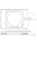
図11は、遮蔽絞り140、145の輻射率を略1とした方法の一例を示した図である。ここで上側には上面図を、下側には断面図を記載した。141は配管であり、設定環境温度、例えば23℃、と同じになるように温度調節された流体を流してある。この際、流体は排熱可能であれば、気体や液体のいずれでも構わない。その一例として、純水などが挙げられる。これによって遮蔽絞り140、145に入射した不要な熱を排熱することが可能となる。また、配管は樹脂、ステンレス等の金属などがあるが、真空中で使用する場合は、部材から排出するガスの観点から金属の方が好ましく、さらに表面を電解研磨等で処理をすることによってその効果がより高くなる。
FIG. 11 is a diagram illustrating an example of a method in which the emissivity of the shielding
図12は、排熱方法の構成としてペルチェ素子を利用したことを示す図である。142は配管を保持するための支持板であり、配管141を保持するとともに後述するペルチェ素子の排熱を伝導する役割をしている。支持板142の材料としては、熱伝導性の良い銅やアルミニウムといったものが好ましい。また、支持板142の下面は後述するペルチェ素子を接合させるために絶縁部を設けてある。143はペルチェ素子である。ペルチェ素子143は、例えば、p型半導体及びn型半導体を熱的に平行に配置して構成される。「ペルチェ効果」とは、2種類の導体や半導体の接点に電流を流すと電導率の違いから熱の移動が起こるという現象である。これによって、ペルチェ素子143の上面、下面で温度差が発生する。例えば、遮蔽絞り140、145が冷やされている場合は、支持板142が暖められることになる。ペルチェ素子143は前述した絶縁部に熱伝導性の良い蒸着、はんだ等の金属メタライズを施し接合している。また、遮蔽絞り140、145には図示していないが、遮蔽絞りの温度変動を計測するための温度計が接合されている。本構成で、遮蔽絞りに不要な熱が入射した場合、次の流れで遮蔽絞りの温度を制御する。まず、遮蔽絞り140、145に設けられた不図示の温度計が上昇する。不図示の温度計の計測値と設定環境温度を比較し、設定環境温度になるようにペルチェ素子143に電流を流す。以上によって、遮蔽絞り140、145の温度は一定に保たれる。なお、ペルチェ素子が動作した際に発熱があるが、これは前述したとおり支持板142を介して配管141に排熱される。
FIG. 12 is a diagram showing that a Peltier element is used as a configuration of the heat discharging method.
以上第一の方法、第二の方法を用いることにより確実に不要な熱を排除することが可能となる。なお、第一の方法で遮蔽絞り140、145を多段にする例を示したがそれを用いてもミラー110、115に影響を及ぼすようである場合は第二の方法のような排熱方法を盛り込んでも良いことは言うまでも無い。
By using the first method and the second method, unnecessary heat can be reliably removed. In addition, the example in which the shielding
図13は不要な熱をより確実に遮蔽した構造を示した概略断面図である。148は光学系を保持する鏡筒である。鏡筒148も熱の影響を低減させるために内面を表面処理しており、例えば、これをステンレスで形成した場合、電解研磨を施してある。Rは鏡筒148から発生する熱である。150、155は遮蔽鏡筒であり、鏡筒の先端に露光光Lの入射を制限する開口部を設けてある。この開口部(この遮蔽鏡筒)は前述した遮蔽絞りと同様の役割をしている。また、遮蔽鏡筒150、155は前述した図11、図12と同様の機能を有しており、本図においては図11と同様の構成となっている。このような構成を取ることによって、鏡筒やその他の部材から発せられる熱(輻射熱)を効果的に制限することが可能となる。また、本図においては、遮蔽鏡筒150、155が支持部材120、125を覆うように配置してあるが、ミラー全体を覆うようにしても良いことは言うまでもない。つまり、この遮蔽鏡筒(遮蔽部材)は、鏡筒等の部材から輻射熱がミラー(特にミラーの光が照射されない領域)に伝わるのを防止する役割を果たすためのものである。従って、好ましくは、光学部材の周囲の領域で、ミラー(光学部材)に入射する光及びミラーから出射する光の光路を遮らず(光路と干渉せず)、ミラーを支持する支持部材と干渉しない領域のほぼ全域を覆うように遮蔽鏡筒を設けるのが好ましい。
FIG. 13 is a schematic sectional view showing a structure in which unnecessary heat is more reliably shielded. 148 is a lens barrel that holds the optical system. The inner surface of the
また、図13では、ミラー(反射部材)を支持する支持部材120をベースプレート130により支持しており、そのベースプレートが遮蔽鏡筒150を支持している。しかしながら、この遮蔽鏡筒130はミラーとは別の部材に支持されている方が好ましい。すなわち、遮蔽鏡筒150はベースプレートとは異なる支持機構により支持されているのが好ましい。尚、その遮蔽鏡筒を支持する支持機構が、ミラーの表面側を輻射により冷却(温度調節)する冷却(温度調節)機構や、ミラーの裏面側を輻射により冷却(温度調節)する冷却(温度調節)機構を支持するように構成しても構わない。
In FIG. 13, a
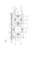
図14は開口径可変の可変NA絞りに不要な熱を遮蔽した構造を取り入れた概略断面図である。本図において、160は可変NA絞り機構である。可変NA絞り機構160は投影ミラーのNAを変えている。この構成を図15において詳細に説明する。
FIG. 14 is a schematic cross-sectional view of a variable NA aperture with a variable aperture diameter that incorporates a structure that shields unnecessary heat. In the figure,
図15はNA絞り機構160を下面から見た図を示している。162a、162bはNA絞りであり、これらの絞りによって投影ミラーのNAを変えている。164は移動板であり、その表面側には配管141、ペルチェ素子143、絞り162a及び162bを保持している。一方、裏面側には必要なNAに応じて、NA絞りを変更できるように後述するスライドガイド166のテーブルが取り付けられている。ここで、移動板164の材質は前出の遮蔽絞り140、145と同様の機能を有するために、熱伝導性の高い材質、例えば、銅やアルミニウムといったものであることが好ましい。また、ペルチェ素子143を貼り付けるために移動板164の上面には遮蔽絞り140、145と同様に絶縁部を設け、その上面にメタライズ処理を施している。166はスライドガイドであり、ガイドレールは不図示の支持板に保持されている。168はボールねじである。ボールねじ168のナット部が移動板164に取り付けられている。移動板164は、ボールねじの片端を回転する(図中Y方向)ことにより、矢視方向(図15中の左右方向)に移動する。以上の構成により、必要時にはNAを可変とし、また、不要な熱はNA絞り機構160によって排除が可能となる。因みに、上記NA絞り機構においては、移動板及びNA絞りの輻射率を略1(0.9以上1.0以下)になるよう仮定して構成した。勿論、輻射率を略0(0以上0.1以下)として構成することも可能であることは言うまでもない。
FIG. 15 is a view of the
上記構成においては、移動機構としてボールねじを利用した方法を示したが、その他の方法、例えば、リニアモータ等を使用しても良い。また、NA絞りを変化させる方法として、絞り162a、162bという二つの絞りを用いて構成したが、所謂虹彩絞り機構(複数の板をカム機構で駆動することにより、絞りの開口径を可変とする絞り機構)を用いたものでも良い。更に、本図においてNA絞り機構160に不要な熱を排除させる機構を設けたが、図13で示した遮蔽鏡筒150、155のような構成にしても良い。また、可変NA絞り機構160と同様の機構を、可変NA絞りを必要とするミラー面以降のミラーの前面に配置し、NAを変更させた際に連動して絞りを変更しても良い。
In the above configuration, a method using a ball screw as the moving mechanism has been described, but another method, for example, a linear motor or the like may be used. Further, as a method of changing the NA aperture, two
上記実施形態においては、輻射冷却機構は、光学部材の露光面側を冷却していたが、勿論光学部材の露光面と反対側の面を冷却しても構わない。すなわち、光学部材がミラーの場合、ミラーの露光面(光が照射される側の面)と反対側の面(裏面)を輻射冷却機構を用いて冷却しても構わない。その際も、光学部材を支持する支持部材や、その他計測機器等を冷却しないようにするために、蒸気実施例に従って輻射遮蔽部材を設けることが望ましい。 In the above embodiment, the radiation cooling mechanism cools the exposed surface side of the optical member. However, it is needless to say that the surface of the optical member opposite to the exposed surface may be cooled. That is, when the optical member is a mirror, the surface (back surface) opposite to the exposure surface (the surface on which light is irradiated) of the mirror may be cooled using a radiation cooling mechanism. In this case, it is desirable to provide a radiation shielding member according to the vapor embodiment in order to prevent the cooling of the supporting member for supporting the optical member and other measuring instruments.
以下、本発明の冷却機構1及び1Aや絞り装置100B又は、それらの任意の組み合わせ(冷却機構1と絞り装置100Bの組み合わせや、冷却機構1Aと絞り装置100Bの組み合わせ)を適用した露光装置3000を図16を用いて説明する。本発明の露光装置3000は露光用の照明光としてEUV光(13〜14nmの波長の光で、例えば、波長13.5nm)を用いる。また、露光装置3000の像面は円弧状(リング状)の像面となり、マスクとウェハを縮小倍率比の速度比でスキャンすることにより、マスクの全面を露光する方式をとる。露光装置3000は、EUV光源3010、照明光学系3030、反射型レチクル3040、アライメント光学系3050、投影光学系3060、レチクルステージ3070、ウェハステージ3080、ウェハ3090を有する。なお、EUV光は大気に対する透過率が低いため、少なくともEUV光が通る光路は真空雰囲気であることが好ましく、照明光学系3030からウェハステージ3080までを真空容器3020に収納している。
Hereinafter, an
本実施形態のEUV光源3010は、例えば、レーザープラズマ光源を使用する。レーザープラズマ光源3010はターゲット供給装置3011によって供給され真空容器3020中に置かれたターゲット材3012に高強度のパルスレーザー光をパルスレーザー3013から集光レンズ3014を介して照射し、高温のプラズマ3015を発生させる。そして、これから放射される波長13.5nm程度のEUV光を利用するものである。ターゲット材3012は、金属薄膜、不活性ガス、液滴などが用いられ、ガスジェット等のターゲット供給装置3011により真空容器内3020に供給される。放射されるEUV光の平均強度を高くするためにはパルスレーザー3013の繰り返し周波数は高い方が良く、通常数kHzの繰り返し周波数で運転される。あるいは、放電プラズマ光源が用いられる。これは真空容器中3020に置かれた電極周辺にガスを放出し、電極にパルス電圧を印加し放電を起こし高温のプラズマを発生させ、これから放射される。
例えば波長13.5nm程度のEUV光を利用するものである。
As the
For example, EUV light having a wavelength of about 13.5 nm is used.
照明光学系3030はEUV光を伝播してマスク又はレチクル(本出願では両者を交換可能に使用する。)3040を照明する。図16において、照明光学系3030は、第1乃至第3ミラー3031、3032及び3033と、オプティカルインテグレータ3034と、アパーチャ3035とを有する。第1ミラー3031はプラズマ3015からほぼ等方的に放射されるEUV光を集める。オプティカルインテグレータ3034はレチクル3040を均一に所定の開口数で照明する。また、それらのEUV光は第2乃至第3ミラー3032乃至3033によってレチクル3040へリレーされる。アパーチャ3035は照明光学系3030のレチクル3040と共役な位置に配置され、レチクル3040面で照明される領域を円弧状に限定する。
The illumination
ここで、照明光学系を構成する第1乃至第3ミラー3031、3032及び3033と、オプティカルインテグレーター3034は、EUV光の入射により加熱されるため、不図示の冷却装置1若しくは1Aを各ミラー毎に配置して、それぞれのミラーを輻射によって冷却する。ここで、冷却装置1と冷却装置1Aのどちらも使用可能であり、露光装置3000の必要スペックや、コスト、許容スペース等を考慮して、適当と判断されたものを選択すれば良い。以下、例として冷却装置1Aを使用した場合についてのみ説明を行う。図16に示す照明光学系3030においては、第1乃至第3ミラー3031、3032及び3033と、オプティカルインテグレーター3034に入射するEUV光の入射角は比較的小さく、露光面と対向する位置に輻射板101Aを配置することは困難である。従って、冷却装置1Aは、図7乃至図9に示す形態で配置するのが好ましい。
Here, the first to
3060は投影光学系である。ここで、より現実的に、本発明の露光装置3000への適用例を説明するために、投影光学系3060の一例として特開2003−45782に示されている反射型投影光学系を挙げる。当該発明である投影光学系3060は、レチクル3040側から光を反射する順番に、第1のミラー3061(凹面鏡)と、第2のミラー3062(凸面鏡)と、第3のミラー3063(凸面鏡)と、第4のミラー3064(凹面鏡)と、第5のミラー3065(凸面鏡)と、第6のミラー3066(凹面鏡)をと有し、第3のミラー3063が開口絞り部分に位置することを特徴としている。当該発明により、結像性能に優れた高NAの光学系を達成することが可能となる。投影光学系3060を構成する第1乃至第6ミラー3061、3062、3063、3064、3065及び3066も、EUV光の入射により加熱されるため、冷却装置1若しくは1Aによって輻射冷却する。投影光学系3060についても、照明光学系3030と同様に、冷却装置1と冷却装置1Aどちらも使用可能である。以下、例として冷却装置1Aを使用した場合についてのみ説明を行う。第1乃至第3ミラー3061、3062及び3063に対するEUV光の入射角は比較的大きく、露光面と対向する位置に輻射板101Aを配置することが可能であるため、図3乃至図4若しくは図6に示す形態で冷却装置1Aを配置するのが好ましい。第4乃至第6ミラー3064、3065、3066に対するEUV光の入射角は比較的小さく、露光面と対向する位置に輻射板101Aを配置することは困難であるため、図7乃至図9に示す形態で冷却装置1Aを配置するのが好ましい。
レチクルステージ3070とウェハステージ3080は、縮小倍率に比例した速度比で同期して走査する機構をもつ。ここで、レチクル3040又はウェハ3090面内で走査方向をX、それに垂直な方向をY、レチクル3040又はウェハ3090面に垂直な方向をZとする。
The
レチクル3040には所望のパターンが形成され、レチクルステージ3070上の図示しないレチクルチャックに保持される。レチクルステージ3070はX方向に移動する機構をもつ。また、X方向、Y方向、Z方向、及び各軸の回りの回転方向に微動機構をもち、レチクル3040の位置決めができるようになっている。レチクルステージ3070の位置と姿勢はレーザ干渉計によって計測され、その結果に基づいて位置と姿勢が制御される。なお、本実施形態ではレチクル3040は反射型レチクルとして実現されているが、投影光学系3060はレチクル3040からの主光線の傾きを小さくすることができ、透過型レチクル又は反射型レチクルのどちらでも適用可能である。
A desired pattern is formed on
ウェハ3090は、図示しないウェハチャックによってウェハステージ3080に保持される。ウェハステージ3080はレチクルステージ3070と同様にX方向に移動する移動機構をもつ。また、X方向、Y方向、Z方向、及び各軸の回りの回転方向に微動機構をもち、ウェハ3090の位置決めができるようになっている。ウェハステージ3080の位置と姿勢はレーザ干渉計によって計測され、その結果に基づいて位置と姿勢が制御される。
アライメント検出光学系3050によってレチクル3040の位置と投影光学系3060の光軸との位置関係、及びウェハ3090の位置と投影光学系3060の光軸との位置関係が計測され、レチクル3040の投影像がウェハ3090の所定の位置に一致するようにレチクルステージ3070及びウェハステージ3080の位置と角度が設定される。また、図示しないフォーカス検出光学系によってウェハ3090面でZ方向のフォーカス位置が計測され、ウェハステージ3080の位置及び角度を制御することによって、露光中は常時ウェハ面を投影光学系3060による結像位置に保つ。
The alignment detection
ウェハ3090上で1回のスキャン露光が終わると、ウェハステージ3080はX、Y方向にステップ移動して次の走査露光開始位置に移動し、再びレチクルステージ3070及びウェハステージ3080が投影光学系の縮小倍率に比例した速度比でX方向に同期走査する。
When one scan exposure is completed on the
このようにして、レチクル3040の縮小投影像がウェハ3090上に結像した状態でそれらを同期走査するという動作が繰り返される。(ステップ・アンド・スキャン)。こうしてウェハ3090全面にレチクル3040の転写パターンが転写される。
In this way, the operation of synchronously scanning the reduced projection images of the
また、EUV光がガスにより吸収されるのを防止するため、EUV光が照射される光学素子が置かれた空間に残留していた炭素を含む分子を付着させないために、EUV光が伝播する空間や光学素子が置かれた空間は、一定の圧力以下に保たれている必要がある。よって、光源や照明光学系3030や投影光学系3060の光学素子、レチクル3040、ウェハ3090などは真空容器3020に入れられ真空度を満たすように排気される。
Further, in order to prevent EUV light from being absorbed by the gas, and to prevent carbon-containing molecules remaining in the space where the optical element irradiated with EUV light is placed from adhering, a space through which EUV light propagates. It is necessary that the space in which the optical elements are placed be kept under a certain pressure. Accordingly, the light source, the optical elements of the illumination
露光において、照明装置220から射出されたEUV光はマスクMSを照明し、マスクMS面上のパターンをレジストを塗布したウエハ等の被処理体W面上に結像する。本実施例において、像面は円弧状(リング状)の像面となり、マスクとウェハを縮小倍率比の速度比でスキャンすることにより、マスクの全面を露光することができる。 In the exposure, the EUV light emitted from the illumination device 220 illuminates the mask MS, and forms a pattern on the surface of the mask MS on the surface of the workpiece W such as a wafer coated with a resist. In this embodiment, the image plane is an arc-shaped (ring-shaped) image plane, and the entire surface of the mask can be exposed by scanning the mask and the wafer at a speed ratio of a reduction ratio.
露光装置の光源部は、本実施例のみに限定されない。例えば、光源部はディスチャージ方式の一つであるZピンチ方式、プラズマ・フォーカス、キャピラリー・ディスチャージ、ホロウカソード・トリガードZピンチ等を使用しても良い。 The light source unit of the exposure apparatus is not limited to this embodiment. For example, the light source unit may use a Z-pinch method which is one of the discharge methods, plasma focus, capillary discharge, hollow cathode triggered Z-pinch, or the like.
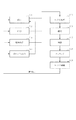
次に、図17及び図18を参照して、上述の露光装置3000を利用したデバイス製造方法の実施例を説明する。図17は、デバイス(ICやLSIなどの半導体チップ、LCD、CCD等)の製造を説明するためのフローチャートである。本実施形態においては、半導体チップの製造を例に説明する。ステップ1(回路設計)では、デバイスの回路設計を行う。ステップ2(マスク製作)では、設計した回路パターンを形成したマスクを製作する。ステップ3(ウェハ製造)では、シリコンなどの材料を用いてウェハを製造する。ステップ4(ウェハプロセス)は、前工程と呼ばれ、マスクとウェハを用いてリソグラフィー技術によってウェハ上に実際の回路を形成する。ステップ5(組み立て)は、後工程と呼ばれ、ステップ4によって作成されたウェハを用いて半導体チップ化する工程であり、アッセンブリ工程(ダイシング、ボンディング)、パッケージング工程(チップ封入)等の工程を含む。ステップ6(検査)では、ステップ5で作成された半導体デバイスの動作確認テスト、耐久性テストなどの検査を行う。こうした工程を経て半導体デバイスが完成し、それが出荷(ステップ7)される。
Next, an embodiment of a device manufacturing method using the above-described
図18は、ステップ4のウェハプロセスの詳細なフローチャートである。ステップ11(酸化)では、ウェハの表面を酸化させる。ステップ12(CVD)では、ウェハの表面に絶縁膜を形成する。ステップ14(イオン打ち込み)では、ウェハにイオンを打ち込む。ステップ15(レジスト処理)では、ウェハに感光剤を塗布する。ステップ16(露光)では、露光装置500によってマスクの回路パターンをウェハに露光する。ステップ17(現像)では、露光したウェハを現像する。ステップ18(エッチング)では、現像したレジスト像以外の部分を削り取る。ステップ19(レジスト剥離)では、エッチングが済んで不要となったレジストを取り除く。これらのステップを繰り返し行うことによってウェハ上に多重に回路パターンが形成される。本実施形態のデバイス製造方法によれば、従来よりも高品位のデバイスを製造することができる。このように、露光装置3000を使用するデバイス製造方法、並びに結果物としてのデバイスも本発明の一側面を構成する。
FIG. 18 is a detailed flowchart of the wafer process in Step 4. Step 11 (oxidation) oxidizes the wafer's surface. Step 12 (CVD) forms an insulating film on the surface of the wafer. Step 14 (ion implantation) implants ions into the wafer. In step 15 (resist processing), a photosensitive agent is applied to the wafer. Step 16 (exposure) uses the
以上、本冷却装置を露光装置に適応した例を示した。本発明の冷却装置はEUV光に限定することなく、他のエキシマレーザ光にも適応することが可能である。また、マスクやウエハなどにも適応することが可能である。 The example in which the present cooling apparatus is applied to the exposure apparatus has been described. The cooling device of the present invention is not limited to EUV light, but can be applied to other excimer laser light. Further, the present invention can be applied to a mask, a wafer, and the like.
本発明の温度調節装置及び方法によれば、真空雰囲気下に配置され、露光により最も高温となる光学部材の露光領域(光照射領域)が熱伝導性が低い材質で構成されていたとしても、光学部材に接触することなく、光学部材を温度調節(冷却)することが可能となるので、結像性能の劣化となる光学部材の熱膨張による変形を低減させて所望の光学性能を実現することができる。 According to the temperature control apparatus and method of the present invention, even if the exposure region (light irradiation region) of the optical member which is placed under a vacuum atmosphere and has the highest temperature by exposure is made of a material having low thermal conductivity, Since the temperature of the optical member can be adjusted (cooled) without contacting the optical member, a desired optical performance can be realized by reducing deformation of the optical member due to thermal expansion, which causes deterioration of imaging performance. Can be.
本実施例の実施態様は以下のように記載することができる。 The embodiment of this example can be described as follows.
(実施態様1) 光学部材を温度調節する温度調節装置であって、
前記光学部材の所定領域に輻射熱を与えることにより温度調節する第1輻射機構と、
前記第1輻射機構からの輻射熱が、前記光学部材内の前記所定領域以外の領域に伝わらないように遮蔽する遮蔽部材とを有することを特徴とする温度調節装置。
(Embodiment 1) A temperature adjusting device for adjusting the temperature of an optical member,
A first radiation mechanism for adjusting the temperature by applying radiant heat to a predetermined region of the optical member,
A temperature control device, comprising: a shielding member that shields radiant heat from the first radiation mechanism from transmitting to a region other than the predetermined region in the optical member.
(実施態様2) 前記遮蔽部材の輻射率が0.1以下もしくは0.9以上であることを特徴とする実施態様1記載の温度調節装置。 (Embodiment 2) The temperature controller according to embodiment 1, wherein the emissivity of the shielding member is 0.1 or less or 0.9 or more.
(実施態様3) 前記遮蔽部材は、前記光学部材に入射する光を制限する絞りの機能を有することを特徴とする実施態様1記載の温度調節装置。 (Embodiment 3) The temperature control device according to Embodiment 1, wherein the shielding member has a function of a diaphragm that restricts light incident on the optical member.
(実施態様4) 前記遮蔽部材は、筒形状をしていることを特徴とする実施態様1記載の温度調節装置。 (Embodiment 4) The temperature control device according to Embodiment 1, wherein the shielding member has a cylindrical shape.
(実施態様5) 前記遮蔽部材の温度を調節する温度調節手段を有することを特徴とする実施態様1記載の温度調節装置。 (Embodiment 5) The temperature controller according to Embodiment 1, further comprising a temperature controller for controlling the temperature of the shielding member.
(実施態様6) 前記光学部材の所定領域は、前記光学部材に光が照射される領域(露光領域S)と略一致していることを特徴とする実施態様1記載の温度調節装置。 (Embodiment 6) The temperature controller according to embodiment 1, wherein the predetermined region of the optical member substantially coincides with a region (exposure region S) where light is irradiated to the optical member.
(実施態様7) 前記光学部材と前記遮蔽部材とが、互いに異なる支持部材により支持されていることを特徴とする実施態様1記載の温度調節装置。 (Embodiment 7) The temperature controller according to embodiment 1, wherein the optical member and the shielding member are supported by different support members.
(実施態様8) 前記光学部材は、反射部材であって、
前記第1輻射機構は、前記光学部材の反射面(表面)に輻射熱を与えることを特徴とする請求項1記載の温度調節装置。
The temperature control device according to claim 1, wherein the first radiation mechanism applies radiation heat to a reflection surface (surface) of the optical member.
(実施態様9) 前記光学部材は、反射部材であって、
前記第1輻射機構は、前記光学部材の反射面(表面)と向かい合っていることを特徴とする実施態様1記載の温度調節装置。
(Embodiment 9) The optical member is a reflection member,
The temperature control device according to claim 1, wherein the first radiation mechanism faces a reflection surface (surface) of the optical member.
(実施態様10) 前記光学部材は、反射部材であって、
前記第1輻射機構は、前記光学部材の反射面(表面)と対向する第1輻射板(第1輻射部材)を有し、該輻射板から前記反射面に輻射熱を与えることを特徴とする実施態様1記載の温度調節装置。
(Embodiment 10) The optical member is a reflection member,
The first radiation mechanism has a first radiation plate (first radiation member) opposed to a reflection surface (surface) of the optical member, and applies radiant heat from the radiation plate to the reflection surface. The temperature control device according to aspect 1.
(実施態様11) 前記第1輻射機構は、前記光学部材の温度調節をする輻射板を有し、
前記輻射板は、円錐の側面の少なくとも一部又は角錐の側面の少なくとも一部又は球体の一部と略同じ形状をしていることを特徴とする実施態様1記載の温度調節装置。
(Embodiment 11) The first radiation mechanism has a radiation plate for adjusting the temperature of the optical member,
The temperature control device according to claim 1, wherein the radiation plate has substantially the same shape as at least a part of a side surface of a cone, at least a part of a side surface of a pyramid, or a part of a sphere.
(実施態様12) 前記第1輻射機構は、前記光学部材の温度調節をする輻射板を有し、
前記輻射板の前記所定領域と向かい合っている輻射面が凹面形状をしており、該輻射面の曲率半径が該輻射面の中心と前記所定領域の中心との距離と同じか、該輻射面の中心と前記所定領域の中心との距離より長いことを特徴とする実施態様1記載の温度調節装置。
(Embodiment 12) The first radiation mechanism has a radiation plate for adjusting the temperature of the optical member,
The radiation surface facing the predetermined region of the radiation plate has a concave shape, and the radius of curvature of the radiation surface is the same as the distance between the center of the radiation surface and the center of the predetermined region, or of the radiation surface. The temperature controller according to claim 1, wherein the distance is longer than a distance between a center and a center of the predetermined area.
(実施態様13) 前記光学部材は、反射部材であって、
前記反射部材の反射面と反対側の面(裏面)に輻射熱を与える第2輻射機構を有することを特徴とする実施態様1記載の温度調節装置。
(Embodiment 13) The optical member is a reflection member,
The temperature control device according to claim 1, further comprising a second radiation mechanism that applies radiant heat to a surface (back surface) of the reflection member opposite to the reflection surface.
(実施態様14) 前記光学部材は、反射部材であって、
前記反射部材の反射面と反対側の面(裏面)と向かい合う第2輻射機構を有することを特徴とする実施態様1記載の温度調節装置。
(Embodiment 14) The optical member is a reflection member,
The temperature control device according to claim 1, further comprising a second radiation mechanism facing a surface (back surface) of the reflection member opposite to the reflection surface.
(実施態様15) 前記光学部材は、反射部材であって、
前記反射部材の反射面と反対側の面(裏面)と対向する第2輻射板を備える第2輻射機構を有しており、
前記第2輻射板(第2輻射部材)から前記反射面と反対側の面に輻射熱を与えることを特徴とする実施態様1記載の温度調節装置。
(Embodiment 15) The optical member is a reflecting member,
A second radiation mechanism including a second radiation plate facing a surface (back surface) of the reflection member opposite to the reflection surface,
The temperature controller according to claim 1, wherein radiant heat is applied from the second radiation plate (second radiation member) to a surface opposite to the reflection surface.
(実施態様16) 前記遮蔽部材は、前記光学部材の周囲の少なくとも一部を覆うように構成されていることを特徴とする実施態様1記載の温度調節装置。 (Embodiment 16) The temperature controller according to embodiment 1, wherein the shielding member is configured to cover at least a part of a periphery of the optical member.
(実施態様17) 前記遮蔽部材は、前記光学部材の周囲の、前記光学部材に入射する光及び前記光学部材から出射する光の光路と異なる領域を覆うように構成されていることを特徴とする実施態様1記載の温度調節装置。 (Embodiment 17) The shielding member is configured to cover an area around the optical member which is different from an optical path of light incident on the optical member and light emitted from the optical member. The temperature controller according to claim 1.
(実施態様18) 光学部材を温度調節する温度調節装置であって、前記光学部材の所定領域に輻射熱を与えることにより温度調節する第1輻射機構と、前記第1輻射機構からの輻射熱が、前記光学部材内の前記所定領域以外の領域に伝わらないように遮蔽する遮蔽部材とを有する温度調節装置を備え、マスクのパターンを基板上に露光することを特徴とする露光装置。 (Embodiment 18) A temperature adjusting device for adjusting the temperature of an optical member, wherein a first radiation mechanism for adjusting the temperature by applying radiant heat to a predetermined area of the optical member, and radiant heat from the first radiant mechanism, An exposure apparatus, comprising: a temperature adjusting device having a shielding member for shielding the optical member from transmitting to an area other than the predetermined area, and exposing a pattern of a mask onto a substrate.
(実施態様19) 光学部材を温度調節する温度調節装置であって、前記光学部材の所定領域に輻射熱を与えることにより温度調節する第1輻射機構と、前記第1輻射機構からの輻射熱が、前記光学部材内の前記所定領域以外の領域に伝わらないように遮蔽する遮蔽部材とを有する温度調節装置を備え、マスクのパターンを基板上に露光する露光装置で前記基板を露光する露光工程と、
前記露光された基板を現像する現像工程とを有することを特徴とするデバイスの製造方法。
(Embodiment 19) A temperature adjustment device for adjusting the temperature of an optical member, wherein a first radiation mechanism for adjusting the temperature by applying radiant heat to a predetermined region of the optical member, and radiant heat from the first radiant mechanism, An exposure step of exposing the substrate with an exposure apparatus that exposes a pattern of a mask on a substrate, comprising a temperature adjustment device having a shielding member that shields the optical member from transmitting to an area other than the predetermined area.
And a developing step of developing the exposed substrate.
(実施態様20) 光源からの光でマスクのパターンを照明する照明光学系と、前記パターンからの光を基板上に投影する投影光学系とを有する露光装置であって、光学部材を温度調節する温度調節装置であって、前記光学部材の所定領域に輻射熱を与えることにより温度調節する第1輻射機構と、前記第1輻射機構からの輻射熱が、前記光学部材内の前記所定領域以外の領域に伝わらないように遮蔽する遮蔽部材とを有する温度調節装置を用いて前記照明光学系及び前記投影光学系が有する少なくとも1つの光学部材の温度調節を行うことを特徴とする露光装置。 (Embodiment 20) An exposure apparatus having an illumination optical system for illuminating a mask pattern with light from a light source and a projection optical system for projecting light from the pattern onto a substrate, wherein the temperature of the optical member is adjusted. A temperature control device, wherein a first radiation mechanism for controlling the temperature by applying radiant heat to a predetermined area of the optical member, and radiant heat from the first radiation mechanism is applied to an area other than the predetermined area in the optical member. An exposure apparatus, wherein a temperature of at least one optical member of the illumination optical system and the projection optical system is adjusted using a temperature adjustment device having a shielding member that shields the light from being transmitted.
(実施態様21) 光源からの光でマスクのパターンを照明する照明光学系と、前記パターンからの光を基板上に投影する投影光学系とを有する露光装置であって、光学部材を温度調節する温度調節装置であって、前記光学部材の所定領域に輻射熱を与えることにより温度調節する第1輻射機構と、前記第1輻射機構からの輻射熱が、前記光学部材内の前記所定領域以外の領域に伝わらないように遮蔽する遮蔽部材とを有する温度調節装置を用いて前記照明光学系及び前記投影光学系が有する少なくとも1つの光学部材の温度調節を行う露光装置で前記基板を露光する露光工程と、
前記露光された基板を現像する現像工程とを有することを特徴とするデバイスの製造方法。
(Embodiment 21) An exposure apparatus having an illumination optical system for illuminating a pattern of a mask with light from a light source and a projection optical system for projecting light from the pattern onto a substrate, wherein the temperature of the optical member is adjusted. A temperature control device, wherein a first radiation mechanism for controlling the temperature by applying radiant heat to a predetermined area of the optical member, and radiant heat from the first radiation mechanism is applied to an area other than the predetermined area in the optical member. An exposure step of exposing the substrate with an exposure apparatus that performs temperature adjustment of at least one optical member that the illumination optical system and the projection optical system have using a temperature adjustment device that has a shielding member that shields from being transmitted;
And a developing step of developing the exposed substrate.
(実施態様22) 真空雰囲気下に置かれた光学部材を温度調節(冷却)する温度調節(冷却)装置であって、
前記光学部材の温度を検出する光学部材温度検出部を有する検出部と、
前記光学部材に非接触で配置され、前記光学部材の露光領域から輻射で熱を吸収する輻射温度調節(冷却)機構と、
前記輻射温度調節(冷却)機構と前記光学部材の露光領域以外の面との輻射伝熱を遮蔽する輻射遮蔽部材と、
前記検出部の検出する前記光学部材の温度が所定の値となるように、前記輻射温度調節(冷却)機構を制御する制御部とを有することを特徴とする温度調節(冷却)装置。
(Embodiment 22) A temperature adjusting (cooling) device for adjusting (cooling) the temperature of an optical member placed in a vacuum atmosphere,
A detection unit having an optical member temperature detection unit for detecting the temperature of the optical member,
A radiation temperature adjustment (cooling) mechanism that is arranged in non-contact with the optical member and absorbs heat by radiation from an exposure region of the optical member;
A radiation shielding member that shields the radiation temperature control (cooling) mechanism and radiation heat transfer between surfaces other than the exposure region of the optical member;
A temperature control (cooling) device comprising: a control unit that controls the radiation temperature control (cooling) mechanism so that the temperature of the optical member detected by the detection unit becomes a predetermined value.
(実施態様23) 前記輻射温度調節(冷却)機構は、冷媒が流れるための流路を有し、
前記光学部材の露光領域に対して温度差を形成する輻射板と、
前記制御部に制御され、前記冷媒を前記流路に循環させる循環部とを有することを特徴とする実施態様22記載の温度調節(冷却)装置。
(Embodiment 23) The radiant temperature adjusting (cooling) mechanism has a flow path through which a refrigerant flows,
A radiation plate that forms a temperature difference with respect to an exposure area of the optical member,
23. The temperature control (cooling) device according to claim 22, further comprising a circulation unit controlled by the control unit to circulate the refrigerant through the flow path.
(実施態様24) 前記冷媒の温度は、可変であることを特徴とする実施態様23記載の温度調節(冷却)装置。 (Embodiment 24) The temperature control (cooling) device according to embodiment 23, wherein the temperature of the refrigerant is variable.
(実施態様25) 前記輻射温度調節(冷却)機構は、前記光学部材に対して温度差を形成する輻射板と、
前記制御部に制御され、前記輻射板に接合してペルチェ効果により前記輻射板を温度調節(冷却)するペルチェ素子と、
冷媒が流れるための流路を有し、
前記ペルチェ素子の排熱を回収する放熱ブロックと、
前記冷媒を前記流路に循環させる循環部とを有することを特徴とする実施態様22記載の温度調節(冷却)装置。
(Embodiment 25) The radiation temperature adjusting (cooling) mechanism includes: a radiation plate that forms a temperature difference with respect to the optical member;
A Peltier element that is controlled by the control unit and that adjusts the temperature of the radiation plate (cooling) by the Peltier effect by joining to the radiation plate;
It has a flow path for the refrigerant to flow,
A heat dissipation block that collects exhaust heat of the Peltier element;
23. The temperature control (cooling) device according to claim 22, further comprising: a circulating unit that circulates the refrigerant through the flow path.
(実施態様26) 前記冷媒の温度は、一定であることを特徴とする実施態様25記載の温度調節(冷却)装置。
(Embodiment 26) The temperature control (cooling) apparatus according to
(実施態様27) 前記輻射板は、露光光が形成する空間以外に、前記光学部材に非接触で配置され、前記光学部材の露光領域との輻射形態係数が略1(0.9以上)に近づく形状を有することを特徴とする実施態様23記載の温度調節(冷却)装置。 (Embodiment 27) The radiating plate is arranged in a non-contact manner with the optical member, except for a space formed by the exposure light, and has a radiation form factor of about 1 (0.9 or more) with the exposure region of the optical member. 24. The temperature control (cooling) device according to embodiment 23, wherein the temperature control (cooling) device has a shape approaching.
(実施態様28) 前記輻射遮蔽部材は、冷媒が流れるための流路と前記制御部に制御され、前記冷媒を前記流路に循環させる循環部とを有することを特徴とする実施態様22記載の温度調節(冷却)装置。 (Embodiment 28) The radiation shielding member according to embodiment 22, characterized in that the radiation shielding member has a flow path through which the refrigerant flows and a circulating unit controlled by the control unit to circulate the refrigerant through the flow path. Temperature control (cooling) device.
(実施態様29) 前記検出部は、前記輻射遮蔽部材の温度を検出する輻射遮蔽部材温度検出部を有し、
前記制御部によって制御される前記冷媒の温度により、前記輻射遮蔽部材温度検出部で検出される前記輻射遮蔽部材の温度が、前記光学部材温度検出部が検出する前記光学部材の温度と等しいことを特徴とする実施態様28記載の温度調節(冷却)装置。
(Embodiment 29) The detection unit includes a radiation shielding member temperature detection unit that detects a temperature of the radiation shielding member,
By the temperature of the refrigerant controlled by the control unit, the temperature of the radiation shielding member detected by the radiation shielding member temperature detection unit, equal to the temperature of the optical member detected by the optical member temperature detection unit. 29. The temperature control (cooling) device according to claim 28, characterized by the fact that:
(実施態様30) 前記輻射遮蔽部材の内部表面の輻射率は略1であることを特徴とする実施態様22記載の温度調節(冷却)装置。 (Embodiment 30) The temperature adjusting (cooling) device according to embodiment 22, wherein the emissivity of the inner surface of the radiation shielding member is substantially 1.
(実施態様31) 前記輻射遮蔽部材は、前記輻射遮蔽部材の開口部に、前記輻射板と前記光学部材の露光領域以外との輻射伝熱を遮蔽する輻射遮蔽絞りを有することを特徴とする実施態様22記載の温度調節(冷却)装置。 (Embodiment 31) The radiation shielding member includes, at an opening of the radiation shielding member, a radiation shielding stop for shielding radiation heat transfer between the radiation plate and an area other than the exposure area of the optical member. A temperature control (cooling) device according to aspect 22.
(実施態様32) 前記輻射遮蔽絞りは、前記光学部材の露光領域に対応して形状が可変であることを特徴とする実施態様31記載の温度調節(冷却)装置。 (Thirty-second embodiment) The temperature adjusting (cooling) device according to the thirty-first embodiment, wherein a shape of the radiation shielding diaphragm is variable corresponding to an exposure area of the optical member.
(実施態様33) 前記検出部は、前記光学部材の露光面温度分布を検出する温度分布検出部を有することを特徴とする実施態様25記載の温度調節(冷却)装置。 (Thirty-third Embodiment) A temperature adjusting (cooling) device according to a twenty-fifth embodiment, wherein the detecting unit includes a temperature distribution detecting unit that detects a temperature distribution of an exposed surface of the optical member.
(実施態様34) 前記輻射温度調節(冷却)機構は、前記輻射板に接合し、前記制御部によって、記温度分布検出部が検出する前記光学部材の露光面の温度分布が均一且つ一定になるように個別に制御される複数の前記ペルチェ素子を有することを特徴とする実施態様33記載の温度調節(冷却)装置。 (Embodiment 34) The radiation temperature adjustment (cooling) mechanism is joined to the radiation plate, and the control section makes the temperature distribution on the exposure surface of the optical member detected by the temperature distribution detection section uniform and constant. The temperature control (cooling) device according to claim 33, comprising a plurality of the Peltier elements individually controlled as described above.
(実施態様35) 前記温度分布検出部は、前記光学部材に接触することなく、前記光学部材の露光面温度分布を検出することを特徴とする実施態様33記載の温度調節(冷却)装置。 (Thirty-fifth Embodiment) A temperature adjusting (cooling) apparatus according to a thirty-third embodiment, wherein the temperature distribution detecting unit detects an exposure surface temperature distribution of the optical member without contacting the optical member.
(実施態様36) 前記制御部は、前記温度分布検出部の検出する値を前記温度温度検出部で検出される値に修正することを特徴とする請求項35記載の温度調節(冷却)装置。 36. The temperature control (cooling) device according to claim 35, wherein the control unit corrects a value detected by the temperature distribution detection unit to a value detected by the temperature / temperature detection unit.
(実施態様37) 前記輻射板は、低い熱伝導率を有することを特徴とする実施態様33記載の温度調節(冷却)装置。 (Embodiment 37) The temperature adjusting (cooling) device according to Embodiment 33, wherein the radiation plate has a low thermal conductivity.
(実施態様38) 真空雰囲気下に置かれた光学部材を温度調節(冷却)する温度調節(冷却)方法であって、
前記光学部材の温度を検出するステップと、
前記検出ステップで検出した前記光学部材の露光領域の温度が所定の値となるように、前記光学部材と非接触で配置されると共に前記光学部材の露光領域の熱を吸収する輻射板との間に温度差を形成するステップとを有することを特徴とする温度調節(冷却)方法。
(Embodiment 38) A temperature adjusting (cooling) method for adjusting (cooling) the temperature of an optical member placed in a vacuum atmosphere,
Detecting the temperature of the optical member;
In such a manner that the temperature of the exposure area of the optical member detected in the detection step becomes a predetermined value, between the optical member and the radiation plate that is arranged in a non-contact manner and absorbs heat of the exposure area of the optical member. Forming a temperature difference in the temperature control (cooling) method.
(実施態様39) 真空雰囲気下に置かれた光学部材を温度調節(冷却)する温度調節(冷却)装置であって、前記光学部材の温度を検出する光学部材温度検出部を有する検出部と、前記光学部材に非接触で配置され、前記光学部材の露光領域から輻射で熱を吸収する輻射温度調節(冷却)機構と、前記輻射温度調節(冷却)機構と前記光学部材の露光領域以外の面との輻射伝熱を遮蔽する輻射遮蔽部材と、前記検出部の検出する前記光学部材の温度が所定の値となるように、前記輻射温度調節(冷却)機構を制御する制御部とを有することを特徴とする温度調節(冷却)装置と、
前記温度調節(冷却)装置により温度調節(冷却)された光学部材を介してマスク又はレチクルに形成されたパターンを被処理体に露光する光学系とを有する露光装置。
(Embodiment 39) A temperature adjustment (cooling) device for adjusting (cooling) the temperature of an optical member placed in a vacuum atmosphere, the detection unit having an optical member temperature detection unit for detecting the temperature of the optical member; A radiation temperature control (cooling) mechanism that is arranged in non-contact with the optical member and absorbs heat by radiation from an exposure region of the optical member; a surface other than the exposure region of the radiation temperature control (cooling) mechanism and the optical member; A radiation shielding member that shields radiation heat transfer between the optical member and a control unit that controls the radiation temperature adjustment (cooling) mechanism so that the temperature of the optical member detected by the detection unit becomes a predetermined value. A temperature control (cooling) device,
An optical system for exposing a pattern on a mask or a reticle to an object to be processed through an optical member whose temperature has been adjusted (cooled) by the temperature adjusting (cooling) device.
(実施態様40) 真空雰囲気下に置かれた光学部材を温度調節(冷却)する温度調節(冷却)装置であって、前記光学部材の温度を検出する光学部材温度検出部を有する検出部と、前記光学部材に非接触で配置され、前記光学部材の露光領域から輻射で熱を吸収する輻射温度調節(冷却)機構と、前記輻射温度調節(冷却)機構と前記光学部材の露光領域以外の面との輻射伝熱を遮蔽する輻射遮蔽部材と、前記検出部の検出する前記光学部材の温度が所定の値となるように、前記輻射温度調節(冷却)機構を制御する制御部とを有することを特徴とする温度調節(冷却)装置と、前記温度調節(冷却)装置により温度調節(冷却)された光学部材を介してマスク又はレチクルに形成されたパターンを被処理体に露光する光学系とを有する露光装置を用いて被処理体を投影露光するステップと、
投影露光された前記被処理体に所定のプロセスを行うステップとを有することを特徴とするデバイス製造方法。
(Embodiment 40) A temperature adjusting (cooling) device for adjusting (cooling) the temperature of an optical member placed in a vacuum atmosphere, the detecting unit having an optical member temperature detecting unit for detecting the temperature of the optical member, A radiation temperature control (cooling) mechanism that is arranged in non-contact with the optical member and absorbs heat by radiation from an exposure region of the optical member; a surface other than the exposure region of the radiation temperature control (cooling) mechanism and the optical member; A radiation shielding member that shields radiation heat transfer between the optical member and a control unit that controls the radiation temperature adjustment (cooling) mechanism so that the temperature of the optical member detected by the detection unit becomes a predetermined value. A temperature adjusting (cooling) device, and an optical system that exposes a pattern formed on a mask or a reticle to an object to be processed through an optical member whose temperature has been adjusted (cooled) by the temperature adjusting (cooling) device. Exposure with Projecting and exposing the object to be processed using the apparatus,
Performing a predetermined process on the object subjected to the projection exposure.
(実施態様41) 光学素子の入射側に設けられ、露光光を制限する絞りにおいて、当該絞りの輻射率が0.1以下もしくは0.9以上であることを特徴とする絞り装置。 (Embodiment 41) A diaphragm device provided on the incident side of an optical element and for limiting exposure light, wherein the emissivity of the diaphragm is 0.1 or less or 0.9 or more.
(実施態様42) 前記絞りは前記光学素子の周囲を覆っていることを特徴とする実施態様41記載の絞り装置。 (Embodiment 42) The diaphragm device according to embodiment 41, wherein the aperture covers the periphery of the optical element.
(実施態様43) 前記絞りは露光光の開口を制限することを特徴とする実施態様41記載の絞り装置。 (Embodiment 43) The diaphragm apparatus according to embodiment 41, wherein the aperture restricts the aperture of the exposure light.
(実施態様44) 前記絞りは温度調節(冷却)装置を有することを特徴とする実施態様41記載の絞り装置。 (Embodiment 44) The diaphragm device according to embodiment 41, wherein the diaphragm has a temperature adjusting (cooling) device.
(実施態様45) 記温度調節(冷却)装置は前記絞りに接合してペルチェ効果により前記絞りを温度調節(冷却)するペルチェ素子と冷媒が流れるための流路を有し、
前記流路は前記ペルチェ素子の排熱を回収することを特徴とする実施態様44記載の絞り装置。
(Embodiment 45) The temperature adjusting (cooling) device has a Peltier element that is joined to the throttle and adjusts (cools) the temperature of the throttle by the Peltier effect, and a flow path for the refrigerant to flow.
The throttling device according to claim 44, wherein said flow path recovers exhaust heat of said Peltier element.
(実施態様46) 前記光学素子はミラーであることを特徴とする実施態様41記載の絞り装置。 (Embodiment 46) The diaphragm according to embodiment 41, wherein the optical element is a mirror.
(実施態様47) 光源からの光でマスク(レチクル)に形成されたパターンを照明する照明光学系と、
前記パターンからの光を被露光体に投影する投影光学系とを有し、
前記照明光学系と前記投影光学系の少なくともいずれか一方が光学素子の入射側に設けられ、露光光を制限する絞りにおいて、当該絞りの輻射率が0.1以下もしくは0.9以上である絞り装置を有していることを特徴とする露光装置。
(Embodiment 47) An illumination optical system for illuminating a pattern formed on a mask (reticle) with light from a light source,
Having a projection optical system that projects light from the pattern onto the object to be exposed,
At least one of the illumination optical system and the projection optical system is provided on an incident side of an optical element, and a diaphragm for limiting exposure light has an emissivity of 0.1 or less or 0.9 or more. An exposure apparatus comprising the apparatus.
(実施態様48) 前記露光装置で用いる光がEUV光であることを特徴とする実施態様47記載の露光装置。 Embodiment 48 The exposure apparatus according to embodiment 47, wherein the light used in the exposure apparatus is EUV light.
(実施態様49) 前記露光装置内において露光光が通る光路の雰囲気が、高真空もしくは実質的にヘリウムガスで満たされていることを特徴とする実施態様47記載の露光装置。 (Embodiment 49) The exposure apparatus according to embodiment 47, wherein the atmosphere of the optical path through which the exposure light passes in the exposure apparatus is filled with high vacuum or substantially with helium gas.
(実施態様50) 光源からの光でマスク(レチクル)に形成されたパターンを照明する照明光学系と、前記パターンからの光を被露光体に投影する投影光学系とを有し、前記照明光学系と前記投影光学系の少なくともいずれか一方が光学素子の入射側に設けられ、露光光を制限する絞りにおいて、当該絞りの輻射率が0.1以下もしくは0.9以上である絞り装置を有している露光装置を用いて被露光体を露光するステップと、
前記露光された前記被処理体に所定のプロセス(現像等)を行うステップとを有することを特徴とするデバイス製造方法。
(Embodiment 50) The illumination optical system includes: an illumination optical system that illuminates a pattern formed on a mask (reticle) with light from a light source; and a projection optical system that projects light from the pattern onto an object to be exposed. At least one of the system and the projection optical system is provided on the incident side of the optical element, and the diaphragm for limiting exposure light has a diaphragm device with an emissivity of 0.1 or less or 0.9 or more. Exposing the object to be exposed by using an exposure apparatus,
Performing a predetermined process (development or the like) on the exposed object to be processed.
(実施態様51) 光学素子の入射側に設けられ、露光光を制限する絞りにおいて、当該絞りの輻射率が0.1以下もしくは0.9以上である絞り装置を備え、
当該絞り装置の開口を介してマスクまたはレチクルに形成されたパターンを被処理体に露光する光学系とを有することを特徴とする露光装置。
(Embodiment 51) A diaphragm provided on the incident side of an optical element, which restricts exposure light, includes a diaphragm device having an emissivity of 0.1 or less or 0.9 or more,
An optical system for exposing an object to be processed with a pattern formed on a mask or a reticle through an opening of the aperture device.
(実施態様52) 前記露光装置で用いる光がEUV光であることを特徴とする実施態様51記載の露光装置。
(実施態様53) 前記露光装置内において露光光が通る光路の雰囲気が、高真空もしくは実質的にヘリウムガスで満たされていることを特徴とする実施態様51記載の露光装置。
(Embodiment 53) The exposure apparatus according to
(実施態様54) 光学素子の入射側に設けられ、露光光を制限する絞りにおいて、当該絞りの輻射率が0.1以下もしくは0.9以上である絞り装置を備え、当該絞り装置の開口を介してマスクまたはレチクルに形成されたパターンを被処理体に露光する光学系とを有する露光装置を用いて被露光体を露光するステップと、
前記露光された前記被処理体に所定のプロセス(現像等)を行うステップとを有することを特徴とするデバイス製造方法。
(Embodiment 54) A diaphragm provided on the incident side of an optical element and limiting the exposure light is provided with a diaphragm device having an emissivity of 0.1 or less or 0.9 or more. Exposing the object to be exposed using an exposure apparatus having an optical system for exposing the object to be processed with a pattern formed on a mask or a reticle through,
Performing a predetermined process (development or the like) on the exposed object to be processed.
(実施態様55) 光学部材を温度調節する温度調節装置は以下を備える;
前記光学部材の所定領域との間で輻射熱の授受を行う第1輻射部材を有し、該第1輻射部材を用いて前記光学部材の温度を調節する第1輻射機構と、
前記第1輻射部材からの輻射熱のうち、前記所定領域以外の領域に伝わる輻射熱の熱量を低減する遮蔽部材。
(Embodiment 55) A temperature control device for controlling the temperature of an optical member includes:
A first radiation member that transmits and receives radiant heat between a predetermined region of the optical member and a first radiation mechanism that adjusts the temperature of the optical member using the first radiation member;
A shielding member that reduces the amount of radiant heat transmitted to a region other than the predetermined region, of the radiant heat from the first radiant member.
(実施態様56) 実施態様55記載の装置であって、
前記遮蔽部材の輻射率が0.1以下もしくは0.9以上である。
Embodiment 56 The device according to embodiment 55, wherein
The emissivity of the shielding member is 0.1 or less or 0.9 or more.
(実施態様57) 実施態様55に記載の装置であって、
前記遮蔽部材は、前記光学部材に入射する光を制限する絞りの機能を有する。
Embodiment 57 The device according to embodiment 55, wherein
The shielding member has a function of an aperture that limits light incident on the optical member.
(実施態様58) 実施態様55に記載の装置であって、
前記遮蔽部材は、前記光学部材と前記第1輻射部材との間の空間の側面を覆う筒形状をしている。
Embodiment 58 The device according to embodiment 55, wherein
The shielding member has a cylindrical shape that covers a side surface of a space between the optical member and the first radiation member.
(実施態様59) 実施態様55に記載の装置はさらに以下を備える;
前記遮蔽部材の温度を調節する温度調節機構。
Embodiment 59 The device according to embodiment 55 further comprises:
A temperature adjusting mechanism for adjusting the temperature of the shielding member.
(実施態様60) 実施態様55に記載の装置であって、
前記光学部材と前記遮蔽部材とが、互いに異なる支持部材により支持されている。
Embodiment 60 The device according to embodiment 55, wherein
The optical member and the shielding member are supported by different support members.
(実施態様61) 実施態様55に記載の装置であって、
前記光学部材は、反射部材であって、
前記第1輻射部材は、前記光学部材の反射面と対向している。
Embodiment 61 The device according to embodiment 55, wherein
The optical member is a reflection member,
The first radiation member faces the reflection surface of the optical member.
(実施態様62) 実施態様55に記載の装置であって、
前記第1輻射板の前記所定領域と向かい合っている輻射面が凹面形状をしており、該輻射面の曲率半径が該輻射面の中心と前記所定領域の中心との距離と同じか、該輻射面の中心と前記所定領域の中心との距離より長い。
Embodiment 62 The device according to embodiment 55, wherein
A radiation surface facing the predetermined region of the first radiation plate has a concave shape, and a radius of curvature of the radiation surface is equal to a distance between a center of the radiation surface and a center of the predetermined region, It is longer than the distance between the center of the surface and the center of the predetermined area.
(実施態様63) 実施態様61に記載の装置はさらに以下を備える;
前記反射部材の反射面と反対側の面と対向する第2輻射部材を有し、該第2輻射部材を用いて前記光学部材の温度を調節する第2輻射機構。
Embodiment 63 The device according to embodiment 61 further comprises:
A second radiation mechanism having a second radiation member facing a surface of the reflection member opposite to the reflection surface, and adjusting a temperature of the optical member using the second radiation member.
(実施態様64) 実施態様55に記載の装置であって、
前記遮蔽部材は、前記光学部材の周囲の少なくとも一部を覆うように構成されている。
Embodiment 64 The device according to embodiment 55, wherein
The shielding member is configured to cover at least a part of a periphery of the optical member.
(実施態様65) 実施態様55に記載の装置はさらに以下を備える;
前記光学部材の温度を検出する温度検出部、
前記温度検出部による検出結果に基づいて前記第1輻射機構を制御する制御部。
Embodiment 65 The device according to embodiment 55 further comprises:
A temperature detector for detecting the temperature of the optical member,
A control unit that controls the first radiation mechanism based on a detection result by the temperature detection unit.
(実施態様66) 実施態様55に記載の装置はさらに以下を備える;
前記第1輻射部材を温度調節する冷媒を流す流路。
Embodiment 66 The device according to embodiment 55 further comprises:
A flow path for flowing a refrigerant for controlling the temperature of the first radiation member.
(実施態様67) 実施態様55に記載の装置はさらに以下を備える;
前記第1輻射部材の前記光学部材と反対側の設けられたペルチェ素子、
前記ペルチェ素子の前記第1輻射部材と反対側に設けられた放熱ブロック、
前記ペルチェ素子に流す電流量を調整することにより、前記第1輻射部材の温度を調節する制御部。
Embodiment 67 The device according to embodiment 55 further comprises:
A Peltier element provided on the opposite side of the first radiation member from the optical member,
A heat radiation block provided on the side of the Peltier element opposite to the first radiation member;
A controller that adjusts a temperature of the first radiation member by adjusting an amount of current flowing through the Peltier element.
(実施態様68) 実施態様67に記載の装置はさらに以下を備える;
前記放熱ブロックに設けられ、前記放熱ブロックの温度を実質的に一定に保つための冷媒を流す流路。
Embodiment 68 The device according to embodiment 67 further comprises:
A flow path provided in the heat-dissipating block for flowing a refrigerant for keeping the temperature of the heat-dissipating block substantially constant.
(実施態様69) 実施態様55に記載の装置であって、
前記遮蔽部材は、前記第1輻射部材からの輻射熱のうち前記所定領域以外の領域に輻射熱が伝わるのを防ぐ。
Embodiment 69 The device according to embodiment 55, wherein
The shielding member prevents radiant heat from being transmitted to a region other than the predetermined region among radiant heat from the first radiating member.
(実施態様70) 露光装置は以下を備える;
光学部材を有し、光源からの光を被露光体に導く光学系、
前記光学部材の所定領域との間で輻射熱の授受を行う第1輻射部材を有し、該第1輻射部材を用いて前記光学部材の温度を調節する第1輻射機構と、
前記第1輻射部材からの輻射熱のうち、前記所定領域以外の領域に伝わる輻射熱の熱量を低減する遮蔽部材。
(Embodiment 70) An exposure apparatus comprises:
An optical system that has an optical member and guides light from a light source to an object to be exposed;
A first radiation member that transmits and receives radiant heat between a predetermined region of the optical member and a first radiation mechanism that adjusts the temperature of the optical member using the first radiation member;
A shielding member that reduces the amount of radiant heat transmitted to a region other than the predetermined region, of the radiant heat from the first radiant member.
(実施態様71) 実施態様70に従う装置であって、
前記光源からの光の波長がEUV光であって、
前記光源から前記被露光体に到る光路上に配置される光学素子がすべて反射光学素子であって、
前記光学部材が収納されている空間の雰囲気が、高真空もしくは実質的にヘリウムガスで満たされている。
Embodiment 71 The device according to embodiment 70, wherein
The wavelength of the light from the light source is EUV light,
All the optical elements arranged on the optical path from the light source to the object to be exposed are reflection optical elements,
The atmosphere in the space in which the optical member is housed is filled with a high vacuum or substantially with helium gas.
(実施態様72) 実施態様70に記載の装置であって、
前記遮蔽部材は、前記第1輻射部材からの輻射熱のうち前記所定領域以外の領域に輻射熱が伝わるのを防ぐ。
Embodiment 72 The apparatus according to embodiment 70, wherein
The shielding member prevents radiant heat from being transmitted to a region other than the predetermined region among radiant heat from the first radiating member.
(実施態様73) デバイスの製造方法は以下を備える;
実施態様70に記載の露光装置を用いて前記被露光体を露光する工程、
前記露光された被露光体を現像する工程。
Embodiment 73 A method for manufacturing a device includes the following;
Exposing the object to be exposed using the exposure apparatus according to embodiment 70,
Developing the exposed object to be exposed.
(実施態様74) 絞り装置は以下を備える;
光学部材の入射側に設けられ、前記光学部材に入射する光を制限する絞り、
ここで、該絞りの輻射率が0.1以下もしくは0.9以上である。
(Embodiment 74) The aperture device includes:
A stop provided on the incident side of the optical member, for limiting light incident on the optical member,
Here, the emissivity of the stop is 0.1 or less or 0.9 or more.
(実施態様75) 露光装置は以下を備える;
光学部材を有し、光源からの光を被露光体に導く光学系、
前記光学部材の入射側に設けられ、前記光学部材に入射する光を制限する絞り、
ここで、該絞りの輻射率が0.1以下もしくは0.9以上である。
(Embodiment 75) An exposure apparatus comprises:
An optical system that has an optical member and guides light from a light source to an object to be exposed;
A stop provided on the incident side of the optical member, for limiting light incident on the optical member,
Here, the emissivity of the stop is 0.1 or less or 0.9 or more.
(実施態様76) デバイスの製造方法は以下を備える;
実施態様75に記載の露光装置を用いて前記被露光体を露光する工程、
前記露光された被露光体を現像する工程。
Embodiment 76 A method for manufacturing a device includes the following;
Exposing the object to be exposed using the exposure apparatus according to embodiment 75,
Developing the exposed object to be exposed.
(実施態様77) 露光装置は以下を備える;
光学部材を有し、光源からの光を被露光体に導く光学系、
前記光学部材の所定領域との間で輻射熱の授受を行う第1輻射部材を有し、該第1輻射部材を用いて前記光学部材の温度を調節する第1輻射機構、
前記第1輻射部材からの輻射熱のうち、前記所定領域以外の領域に伝わる輻射熱の熱量を低減する遮蔽部材、
前記光学部材の温度を検出する温度検出機構、
前記温度検出機構による検出結果に基づいて前記光学部材の温度調節を行う制御機構。
(Embodiment 77) An exposure apparatus comprises:
An optical system that has an optical member and guides light from a light source to an object to be exposed;
A first radiating member that transmits and receives radiant heat to and from a predetermined region of the optical member, and controls a temperature of the optical member by using the first radiating member;
Of the radiant heat from the first radiant member, a shielding member that reduces the amount of radiant heat transmitted to an area other than the predetermined area,
A temperature detection mechanism for detecting the temperature of the optical member,
A control mechanism for adjusting the temperature of the optical member based on a detection result by the temperature detection mechanism.
(実施態様78) 実施態様77に従う装置であって、
前記制御機構が、前記検出結果及び前記被露光体を露光する露光スケジュールとに基づいて、前記光学部材の温度調節を行う。
Embodiment 78 The device according to embodiment 77, wherein
The control mechanism adjusts the temperature of the optical member based on the detection result and an exposure schedule for exposing the object to be exposed.
(実施態様79) 実施態様77に従う装置はさらに以下を備える;
前記第1輻射部材の前記光学部材と反対側に設けられたペルチェ素子、
前記ペルチェ素子の前記第1輻射部材と反対側に設けられた放熱ブロック、
前記放熱ブロック内に設けられ、実質的に温度が一定の冷媒を流すための流路、
前記ペルチェ素子に流す電流量を調節することにより、前記第1輻射部材の温度を調節する制御機構。
Embodiment 79 The device according to embodiment 77 further comprises:
A Peltier element provided on the opposite side of the first radiation member from the optical member,
A heat radiation block provided on the side of the Peltier element opposite to the first radiation member;
A flow path provided in the heat-dissipating block, for flowing a refrigerant having a substantially constant temperature,
A control mechanism for adjusting the temperature of the first radiation member by adjusting the amount of current flowing through the Peltier element.
(実施態様80) デバイスの製造方法は以下を備える;
実施態様77に記載の露光装置を用いて前記被露光体を露光する工程、
前記露光された被露光体を現像する工程。
Embodiment 80 A method for manufacturing a device includes the following;
Exposing the object to be exposed using the exposure apparatus according to embodiment 77,
Developing the exposed object to be exposed.
Claims (26)
前記光学部材の所定領域との間で輻射熱の授受を行う第1輻射部材を含み、該第1輻射部材を用いて前記光学部材の温度を調節する第1輻射機構と、
前記第1輻射部材からの輻射熱のうち、前記所定領域以外の領域に伝わる輻射熱の熱量を低減する遮蔽部材とを備えることを特徴とする温度調節装置。 A temperature controller for controlling the temperature of the optical member,
A first radiating member that transmits and receives radiant heat between a predetermined region of the optical member and a first radiating mechanism that adjusts the temperature of the optical member using the first radiating member;
A temperature control device, comprising: a shielding member that reduces the amount of radiant heat transmitted to a region other than the predetermined region, of the radiant heat from the first radiant member.
Priority Applications (1)
| Application Number | Priority Date | Filing Date | Title |
|---|---|---|---|
| JP2004120369A JP2004336026A (en) | 2003-04-15 | 2004-04-15 | Thermostat, exposure device having the same, and manufacturing method of device |
Applications Claiming Priority (2)
| Application Number | Priority Date | Filing Date | Title |
|---|---|---|---|
| JP2003110209 | 2003-04-15 | ||
| JP2004120369A JP2004336026A (en) | 2003-04-15 | 2004-04-15 | Thermostat, exposure device having the same, and manufacturing method of device |
Publications (2)
| Publication Number | Publication Date |
|---|---|
| JP2004336026A true JP2004336026A (en) | 2004-11-25 |
| JP2004336026A5 JP2004336026A5 (en) | 2007-06-07 |
Family
ID=33513165
Family Applications (1)
| Application Number | Title | Priority Date | Filing Date |
|---|---|---|---|
| JP2004120369A Withdrawn JP2004336026A (en) | 2003-04-15 | 2004-04-15 | Thermostat, exposure device having the same, and manufacturing method of device |
Country Status (1)
| Country | Link |
|---|---|
| JP (1) | JP2004336026A (en) |
Cited By (4)
| Publication number | Priority date | Publication date | Assignee | Title |
|---|---|---|---|---|
| KR100839859B1 (en) * | 2005-11-18 | 2008-06-20 | 캐논 가부시끼가이샤 | Exposure apparatus and device manufacturing method |
| JP2008277822A (en) * | 2007-05-04 | 2008-11-13 | Asml Holding Nv | Lithographic apparatus |
| JP2011029511A (en) * | 2009-07-28 | 2011-02-10 | Nikon Corp | Optical system, exposure device and method of manufacturing device |
| JP2016533537A (en) * | 2013-09-30 | 2016-10-27 | カール・ツァイス・エスエムティー・ゲーエムベーハー | Optical imaging device by simple manufacturing method |
-
2004
- 2004-04-15 JP JP2004120369A patent/JP2004336026A/en not_active Withdrawn
Cited By (4)
| Publication number | Priority date | Publication date | Assignee | Title |
|---|---|---|---|---|
| KR100839859B1 (en) * | 2005-11-18 | 2008-06-20 | 캐논 가부시끼가이샤 | Exposure apparatus and device manufacturing method |
| JP2008277822A (en) * | 2007-05-04 | 2008-11-13 | Asml Holding Nv | Lithographic apparatus |
| JP2011029511A (en) * | 2009-07-28 | 2011-02-10 | Nikon Corp | Optical system, exposure device and method of manufacturing device |
| JP2016533537A (en) * | 2013-09-30 | 2016-10-27 | カール・ツァイス・エスエムティー・ゲーエムベーハー | Optical imaging device by simple manufacturing method |
Similar Documents
| Publication | Publication Date | Title |
|---|---|---|
| US7250616B2 (en) | Temperature adjustment apparatus, exposure apparatus having the same, and device fabricating method | |
| US7191599B2 (en) | Cooling apparatus and method, and exposure apparatus having the cooling apparatus | |
| KR100806279B1 (en) | Lithographic Apparatus, Collector and Device Manufacturing Method | |
| US7145632B2 (en) | Cooling apparatus | |
| US7212274B2 (en) | Cooling system, exposure apparatus having the same, and device manufacturing method | |
| JP4307130B2 (en) | Exposure equipment | |
| US20090103063A1 (en) | Cooling apparatus for optical member, barrel, exposure apparatus, and device manufacturing method | |
| US7360366B2 (en) | Cooling apparatus, exposure apparatus, and device fabrication method | |
| JP4458323B2 (en) | Holding apparatus, exposure apparatus having the holding apparatus, and device manufacturing method | |
| US7295284B2 (en) | Optical system, exposure apparatus using the same and device manufacturing method | |
| JP4532835B2 (en) | Cooling device, optical member having the same, and exposure apparatus | |
| US7081949B2 (en) | Illumination apparatus, projection exposure apparatus, and device fabrication method | |
| JP2004259778A (en) | Cooling mechanism | |
| KR20050063730A (en) | Lithographic apparatus and device manufacturing method | |
| JP4018564B2 (en) | Optical system, exposure apparatus using the same, and device manufacturing method | |
| JP2004080025A (en) | Cooling device and method therefor, and aligner therewith | |
| JP2004336026A (en) | Thermostat, exposure device having the same, and manufacturing method of device | |
| US7053989B2 (en) | Exposure apparatus and exposure method | |
| JP2004247473A (en) | Cooling device and method, and aligner including the same | |
| JP2004335585A (en) | Cooling device, aligner equipped therewith, method of manufacturing device and cooling method |
Legal Events
| Date | Code | Title | Description |
|---|---|---|---|
| A521 | Written amendment |
Free format text: JAPANESE INTERMEDIATE CODE: A523 Effective date: 20070413 |
|
| A621 | Written request for application examination |
Free format text: JAPANESE INTERMEDIATE CODE: A621 Effective date: 20070413 |
|
| A977 | Report on retrieval |
Free format text: JAPANESE INTERMEDIATE CODE: A971007 Effective date: 20091125 |
|
| A761 | Written withdrawal of application |
Free format text: JAPANESE INTERMEDIATE CODE: A761 Effective date: 20100129 |
|
| RD04 | Notification of resignation of power of attorney |
Free format text: JAPANESE INTERMEDIATE CODE: A7424 Effective date: 20100201 |