JP2004335086A - First writing structure for perpendicular thin film head - Google Patents
First writing structure for perpendicular thin film head Download PDFInfo
- Publication number
- JP2004335086A JP2004335086A JP2004129406A JP2004129406A JP2004335086A JP 2004335086 A JP2004335086 A JP 2004335086A JP 2004129406 A JP2004129406 A JP 2004129406A JP 2004129406 A JP2004129406 A JP 2004129406A JP 2004335086 A JP2004335086 A JP 2004335086A
- Authority
- JP
- Japan
- Prior art keywords
- magnetic
- pole piece
- probe
- head portion
- head
- Prior art date
- Legal status (The legal status is an assumption and is not a legal conclusion. Google has not performed a legal analysis and makes no representation as to the accuracy of the status listed.)
- Pending
Links
Images
Classifications
-
- G—PHYSICS
- G11—INFORMATION STORAGE
- G11B—INFORMATION STORAGE BASED ON RELATIVE MOVEMENT BETWEEN RECORD CARRIER AND TRANSDUCER
- G11B5/00—Recording by magnetisation or demagnetisation of a record carrier; Reproducing by magnetic means; Record carriers therefor
- G11B5/127—Structure or manufacture of heads, e.g. inductive
- G11B5/1278—Structure or manufacture of heads, e.g. inductive specially adapted for magnetisations perpendicular to the surface of the record carrier
-
- G—PHYSICS
- G11—INFORMATION STORAGE
- G11B—INFORMATION STORAGE BASED ON RELATIVE MOVEMENT BETWEEN RECORD CARRIER AND TRANSDUCER
- G11B5/00—Recording by magnetisation or demagnetisation of a record carrier; Reproducing by magnetic means; Record carriers therefor
- G11B5/127—Structure or manufacture of heads, e.g. inductive
- G11B5/31—Structure or manufacture of heads, e.g. inductive using thin films
- G11B5/3103—Structure or manufacture of integrated heads or heads mechanically assembled and electrically connected to a support or housing
Landscapes
- Engineering & Computer Science (AREA)
- Manufacturing & Machinery (AREA)
- Magnetic Heads (AREA)
Abstract
Description
本発明は、薄膜磁気ヘッドに関する。より詳細には、本発明は書込みヘッドが読取りヘッドの下方に位置するヘッドに関する。 The present invention relates to a thin-film magnetic head. More particularly, the invention relates to a head where the write head is located below the read head.
典型的なヘッドにおいては、誘導書込みヘッドは第1、第2及び第3の絶縁層(絶縁スタック)内に埋め込まれた1個のコイル層を含んでおり、該絶縁スタックは第1及び第2の極片層の間に位置している。書込みヘッドの空気ベアリング面(ABS)では、1個のギャップ層により、第1及び第2の極片層の間にギャップが形成されている。極片層は、バックギャップにおいて接続されている。電流がコイル層に通され、該コイル層は極片内に磁界を生ずる。磁界はABSにおいてギャップを横断して並び、動いている媒体、例えば回転している磁気ディスク上の円形トラックもしくは移動している磁気テープ上の長手方向のトラックに、磁界情報の情報単位を書き込む。 In a typical head, an inductive write head includes a single coil layer embedded within first, second and third insulating layers (insulating stacks), the insulating stacks comprising first and second insulating layers. Are located between the pole piece layers. In the air bearing surface (ABS) of the write head, one gap layer forms a gap between the first and second pole piece layers. The pole piece layers are connected at the back gap. Current is passed through the coil layer, which creates a magnetic field in the pole piece. The magnetic field lines up across the gap in the ABS and writes information units of magnetic field information on a moving medium, for example a circular track on a rotating magnetic disk or a longitudinal track on a moving magnetic tape.
第2極片層は、ABSからフレア点に伸びる極片部分と、フレア点からバックギャップに伸びるヨーク部分を持つ。フレア点は、第2極片が広がり(フレア)始め、ヨークを形成する場所である。フレア点の配置は、記録媒体に情報を書き込むために発生される磁界の大きさに直接影響を及ぼす。磁束は幅の狭い第2極片の長さに沿って伝わる間に減衰するので、第2極片を短くすれば、記録媒体に到達する磁束は増すであろう。従って、フレア点を積極的にABSに近付けるように配置することにより、性能を最適化することができる。 The second pole piece layer has a pole piece portion extending from the ABS to the flare point and a yoke portion extending from the flare point to the back gap. The flare point is where the second pole piece begins to spread (flare) and form a yoke. The location of the flare point directly affects the magnitude of the magnetic field generated to write information on the recording medium. Since the magnetic flux attenuates as it travels along the length of the narrow second pole piece, shortening the second pole piece will increase the magnetic flux reaching the recording medium. Therefore, performance can be optimized by arranging the flare point so as to approach the ABS positively.
書込みヘッドの設計上重要なもう一つのパラメータはゼロ・スロート・ハイト(ZTH)である。先行技術におけるゼロ・スロート・ハイトは、ABSを過ぎて、第1及び第2の磁極片が初めて互に分離する場所である。ZTHにおける分離は絶縁層、典型的には絶縁スタック内の第1絶縁層によって行われる。第1及び第2磁極片の間の磁束の漏れは、ZTHをできる限りABSに近接配置することによって最小限度に抑えられる。 Another parameter important in the design of the write head is zero throat height (ZTH). The zero throat height in the prior art is where the first and second pole pieces separate from each other for the first time past the ABS. Isolation in the ZTH is provided by an insulating layer, typically a first insulating layer in an insulating stack. Flux leakage between the first and second pole pieces is minimized by placing the ZTH as close as possible to the ABS.
不幸にして、第2磁極端の製作においては、上に述べた設計諸要素のトレードオフが必要になる。回転しているディスク上に明晰度良好に書き込まれたトラックを作り出すためには、第2磁極端の明晰度が良好でなければならない。第2磁極端の明晰度が劣悪ならば、隣接するトラックの過剰書き込みが起こるおそれがある。明晰度の良好な第2磁極端は、平行でABSに垂直な平面状の側壁と、予測可能な大きさを持たねばならない。この明晰度は、第2磁極端が典型的にはヨークと共に、第1絶縁層、コイル層及び第2と第3の絶縁層が形成された後に形成されるため、達成困難である。それぞれの絶縁層には、硬く焼き付けされ、傾斜した前面を持つフォトレジストが含まれている。 Unfortunately, the fabrication of the second pole tip requires a trade-off between the design elements described above. In order to create a track with good clarity on a rotating disk, the second pole tip must have good clarity. If the clarity of the second magnetic pole tip is inferior, there is a possibility that the adjacent track may be overwritten. The second pole tip with good clarity must have parallel and perpendicular to the ABS, planar sidewalls, and a predictable size. This clarity is difficult to achieve because the second pole tip is typically formed after the first insulating layer, the coil layer, and the second and third insulating layers have been formed with the yoke. Each insulating layer includes a hard baked photoresist having a sloping front surface.
構成後の第1、第2及び第3絶縁層は傾斜した前面を呈し、これらがABSに向き合う。ZTHを定義する層は、ABSに垂直な面から、その面に対しある角度(先端角)で立ち上がる。絶縁層を硬く焼き付けし、金属のシード層を被着させた後には、絶縁層の傾斜した表面は高い反射率を示す。第2磁極端とヨークが形成される際には、絶縁層の上面にフォトレジスト層がスピンコート法で被着され、在来のフォトリソグラフィ技術を用いてフォトパターニングすることにより第2磁極端が形成される。フォトリソグラフィの光イメージング工程では、紫外光を不透明マスクに設けられたスリットを通して導き、フォトレジストの、後の現像工程で除去されるべき領域を露光する。除去されるべき領域の一つは、めっきによって第2磁極片(磁極端とヨーク)が形成される領域である。 The first, second and third insulating layers after construction present an inclined front face, which face the ABS. The layer defining ZTH rises from a plane perpendicular to the ABS at an angle (tip angle) to that plane. After baking the insulation layer hard and depositing a metal seed layer, the inclined surface of the insulation layer shows high reflectivity. When the second pole tip and the yoke are formed, a photoresist layer is applied on the upper surface of the insulating layer by spin coating, and the second pole tip is formed by photo-patterning using a conventional photolithography technique. It is formed. In an optical imaging step of photolithography, ultraviolet light is directed through a slit provided in an opaque mask to expose a region of the photoresist that is to be removed in a subsequent development step. One area to be removed is the area where the second pole piece (pole tip and yoke) is formed by plating.
不幸にして紫外光が第2磁極片のフレア領域における絶縁層の傾斜した表面を照射する時に、紫外光は前方(ABS方向)に反射され、第2磁極端領域の両端部分に入射する。現像後、フォトレジストの両側壁は意図された紫外パターンよりも外向きに広がり、その中にめっきされる磁極端の形成不良を引き起こす。これは「反射ノッチング」と呼ばれる。上に述べたように、これは回転しているディスク上にある隣接トラックの過剰書き込みを引き起こす。フレア点をヘッド内に十分後退させるならば、反射ノッチングの影響が弱められるか、あるいは消失することは明白であろう。反射ノッチングは、傾斜した表面の背後で発生するからである。しかるに、この解決策では第2磁極端が長くなり、そのため記録媒体に到達する磁束の量が急速に減衰する。 Unfortunately, when the ultraviolet light irradiates the inclined surface of the insulating layer in the flare region of the second pole piece, the ultraviolet light is reflected forward (in the ABS direction) and enters both ends of the second pole tip region. After development, the sidewalls of the photoresist spread more outward than the intended ultraviolet pattern, causing poor formation of pole tips plated therein. This is called "reflective notching". As mentioned above, this causes overwriting of adjacent tracks on the spinning disk. It will be apparent that if the flare point is retracted sufficiently into the head, the effects of reflection notching will be reduced or eliminated. Reflective notching occurs behind inclined surfaces. However, this solution lengthens the second pole tip, which causes the amount of magnetic flux reaching the recording medium to decay rapidly.
絶縁スタックの断面が高いと、ウェハ上にフォトレジストがスピンコートされた後に、もう一つの問題が起こる。ウェハ上にスピンコートされる際、フォトレジストはウェハを横断して平坦化される。ウェハ上における第2磁極端の高さが第2磁極片のヨーク部分よりも実質的に低いため、第2磁極端領域におけるレジストの厚さはヘッドの他の領域よりも大きい。露光工程の間、光は深いフォトレジスト中では水中の光と同様に次第に散乱の程度を強め、露光工程中における分解能低下の原因となる。 The high cross section of the insulating stack creates another problem after the photoresist is spin-coated on the wafer. When spin-coated on the wafer, the photoresist is planarized across the wafer. Because the height of the second pole tip on the wafer is substantially lower than the yoke portion of the second pole piece, the thickness of the resist in the second pole tip region is greater than in other regions of the head. During the exposure process, the light gradually increases the degree of scattering in the deep photoresist, as does light in water, causing a reduction in resolution during the exposure process.
反射ノッチングと分解能低下の問題を極小化するための、先行技術によるもう一つの案は、平坦化された表面上に高分解能の磁極端を形成することである。下部第2磁極端を最初に、絶縁層に先立って形成し、反射ノッチングの問題を排除する。高分解能の第1磁極片層、及び書込みギャップ層を形成した後に、加工はコイル層及び第2・第3絶縁層の製作に進むことができる。その後に、上部の、幅の広い磁極端が下部の第2磁極端に縫合(接続)され、ABSからバックギャップまで延長する。下部の第2磁極端は良好に成形され、その大きさは予測可能である故、この製作方法は、長手記録型ヘッド構造における一進歩である。 Another solution according to the prior art to minimize the problem of reflection notching and resolution loss is to form a high resolution pole tip on a planarized surface. A lower second pole tip is first formed prior to the insulating layer, eliminating the problem of reflective notching. After forming the high resolution first pole piece layer and the write gap layer, processing can proceed to the fabrication of the coil layer and the second and third insulating layers. Thereafter, the upper, wider pole tip is sutured (connected) to the lower second pole tip, extending from the ABS to the back gap. This fabrication method is an advance in longitudinal recording head construction because the lower second pole tip is well formed and its size is predictable.
ところが、このヘッドでは、ZTHは下部の高分解能磁極端に関する絶縁層の位置によって決定される。下部の磁極端は、十分な縫合部分を用意するために足る長さを持たねばならず、この長さのために第1及び第2磁極片の間で磁束漏れが発生するおそれがある。上部の第2磁極端は下部の高分解能磁極端よりも幅が広いのが普通であるため、ABSにおける第2磁極片はT字型の形状を持つ。T字の縦部分は高分解能磁極端の前端であり、T字の横棒は上部第2磁極端の前端である。この形状に関する問題は、ABSにおいて、磁束が上部第2磁極端の両外隅からはるかに幅の広い第1磁極片に向かって並び、隣接するトラックの過剰書き込みを起こすことである。 However, in this head, ZTH is determined by the position of the insulating layer with respect to the lower high-resolution pole tip. The lower pole tip must be long enough to provide sufficient sutures, which can cause magnetic flux leakage between the first and second pole pieces. Since the upper second pole tip is typically wider than the lower high-resolution pole tip, the second pole piece in the ABS has a T-shape. The vertical portion of the T is the front end of the high-resolution pole tip, and the horizontal bar of the T is the front end of the upper second pole tip. The problem with this shape is that in ABS, the magnetic flux lines up from the outer corners of the upper second pole tip to the much wider first pole piece, causing overwriting of adjacent tracks.
先行技術による他の一実施形態では、高分解能磁極端が絶縁スタックの上に位置している。該高分解能磁極端が形成されたならば、磁極端間の磁束移動が下部第2磁極端によって定義されるトラック幅を越えて漂遊しないように、高分解能磁極端の下にあり、第2磁極端の基盤における第1及び第2の端に向き合う第1磁極片の第1磁極端をノッチングすることが望ましい。このノッチングにより、実質的に高分解能の第2磁極端のトラック幅と一致するトラック幅を有する第1磁極片が得られる。第1磁極片をノッチングするための先行技術によるプロセスの一つは、下部の第2磁極端をマスクとして用いる、ギャップ層ならびに第1磁極片のイオンビーム切削を伴う。 In another prior art embodiment, a high resolution pole tip is located above the insulating stack. Once the high-resolution pole tip has been formed, it is below the high-resolution pole tip so that the flux transfer between the pole tips does not stray beyond the track width defined by the lower second pole tip. It is desirable to notch the first pole tip of the first pole piece facing the first and second ends of the extreme base. This notching results in a first pole piece having a track width that substantially matches the track width of the second pole tip with high resolution. One prior art process for notching the first pole piece involves ion beam cutting of the gap layer as well as the first pole piece using the lower second pole tip as a mask.
ギャップ層は典型的にはアルミナであり、第1及び第2の磁極端は典型的にはパーマロイ(NiFe)である。アルミナはパーマロイよりも緩慢に切削されるので、下部第2磁極端の上部と第1磁極片の上面は、ギャップ層よりも急速に切削される。更に、イオン切削の間に、仕掛品の表面に相当量のアルミナが再被着(リデップ)する。リデップをできる限り少なくするため、切削のためのイオンビームは典型的には法線に対しある角度を持って各層に入射するように指向される。これによって切削とクリーンアップが同時に行われる。イオンビームに角度が付けられている場合、下部第2磁極端によって第1及び第2の端に遮蔽効果が生ずるので、この下部第2磁極端の第1及び第2の端から離れた領域にあるギャップ層がまず切削される。 The gap layer is typically alumina, and the first and second pole tips are typically permalloy (NiFe). Since alumina is cut more slowly than permalloy, the upper portion of the lower second pole tip and the upper surface of the first pole piece are cut faster than the gap layer. Further, during ion cutting, a significant amount of alumina is redeposited (redepped) on the surface of the workpiece. To minimize redepipation, the ion beam for cutting is typically directed at each layer at an angle to the normal. Thereby, cutting and cleanup are performed simultaneously. When the ion beam is angled, the lower second pole tip causes a shielding effect at the first and second ends, so that the lower second pole tip is located in a region away from the first and second ends. A gap layer is first cut.
この場合、イオン流は、ノッチングが行われるべき領域内の、下部第2磁極端の第1及び第2の端に隣接するギャップ層が除去される以前に、第1磁極片を過剰切削してしまうであろう。ノッチングが行われるべき場所の上でギャップ層が除去された後に、イオン切削は続き、第1磁極片を切削する。第1磁極片の過剰切削がノッチを越える部分に起こり続け、それによってノッチから下方に傾斜した第1磁極片の表面が形成される。知られているように、そのような第1磁極片の過剰切削によって接続リード線をMRセンサ又は幅の広いヘッドのコイルに対して露出させ、それによってヘッドの作動能力を失わせることがある。 In this case, the ion stream overcuts the first pole piece before the gap layer adjacent to the first and second ends of the lower second pole tip in the region to be notched is removed. Will be gone. After the gap layer has been removed where notching is to be performed, ion cutting continues and cuts the first pole piece. Overcutting of the first pole piece continues to occur beyond the notch, thereby forming a surface of the first pole piece that slopes down from the notch. As is known, such over-cutting of the first pole piece may expose the connecting lead to the MR sensor or the coil of the wide head, thereby losing the head's operating capability.
第1磁極片の過剰切削を制御することができても、更に厄介な問題、すなわちギャップ層の望ましくない部分が切削され、ノッチが形成される場合には、高分解能の第2磁極端の過剰切削という問題が生ずる可能性がある。この過剰切削を補償するために、アスペクト比(高分解能の第2磁極端のトラック幅に対するフォトレジストの厚さの比)を増やし、切削工程の間に高分解能の下部第2磁極片頂上の上の部分を切り捨て得るようにする。アスペクト比を高める場合、上に論じたフォトレジストの厚さのために高分解能の第2磁極端の明晰度は劣化し、トラックの過剰書込みが起こる。 Even though the overcutting of the first pole piece can be controlled, a further complication is that if the undesired part of the gap layer is cut off and a notch is formed, the excess of the high resolution second pole tip The problem of cutting can occur. To compensate for this over-cutting, the aspect ratio (ratio of photoresist thickness to track width of the high-resolution second pole tip) is increased so that during the cutting process, the top of the high-resolution lower second pole piece tops. Part can be truncated. When the aspect ratio is increased, the clarity of the high resolution second pole tip is degraded due to the photoresist thickness discussed above, and overwriting of tracks occurs.
先行技術の合体式MRヘッドに関するもう一つの問題は、第1及び第2ギャップ層の間のMRセンサのプロファイルが第2遮蔽/第1磁極片層を通じて書込みギャップ層に複製され、該書込みギャップ層をMRセンサに対して多少凹面に湾曲させることである。組合せMRヘッドの書込みヘッド部分がデータを書き込む時、書き込まれたデータは書き込まれたトラック上で僅かに曲げられる。直線交差のMRセンサがこの曲がったデータを読み取る場合、データトラックの中心からデータトラックの外側の端に向かって、信号損失が次第に大きくなる。 Another problem with prior art merged MR heads is that the profile of the MR sensor between the first and second gap layers is replicated through the second shield / first pole piece layer to the write gap layer. Is curved somewhat concavely with respect to the MR sensor. When the write head portion of the combination MR head writes data, the written data is slightly bent on the written track. When an MR sensor at a straight intersection reads this bent data, the signal loss gradually increases from the center of the data track to the outer edge of the data track.
あらゆる組合せ磁気ヘッドは、読取りギャップと書込みギャップの間に分離を持つ。この分離のために、磁気ヘッドが磁気ディスクの外寄りのトラック上にある時には、ずれが起こる。最も内側のトラックでは、読取りギャップと書込みギャップは実質的に一線に並んでおり、実質的にずれは存在しない。最も内側のトラックでは、読取りギャップは書込みギャップによって書き込まれたトラック内を追従する。しかし、アクチュエータが磁気ヘッドを最も外側のトラックにスイングさせると、トラックに関する読取りヘッドと書込みヘッドの整列が不良になる。書込みギャップが書き込み中のトラック内にあっても、読取りギャップが一部は該トラック内に、一部は隣接トラック内にあるかも知れない。ずれは、読取りギャップと書込みギャップの間の分離が増大するに従って増加する。書込みヘッドが読取りヘッドに先んじて製作される磁気ヘッドでは、書込みヘッドの絶縁スタックのプロファイルが、読取りヘッドの第1遮蔽層の高さを高める。このプロファイルを縮小し、読取りギャップと書込みギャップを相互に接近させ得るならは、好ましいであろう。 Every combination magnetic head has a separation between the read gap and the write gap. Due to this separation, a shift occurs when the magnetic head is on an outer track of the magnetic disk. In the innermost track, the read gap and the write gap are substantially aligned and there is substantially no shift. In the innermost track, the read gap follows the track written by the write gap. However, if the actuator swings the magnetic head to the outermost track, the read and write heads will be misaligned with respect to the track. Even though the write gap is in the track being written, the read gap may be partially in the track and partially in an adjacent track. The offset increases as the separation between the read gap and the write gap increases. In magnetic heads in which the write head is manufactured prior to the read head, the profile of the insulating stack of the write head increases the height of the first shield layer of the read head. It would be desirable if this profile could be reduced so that the read and write gaps could be brought closer together.
先行技術の磁気ヘッドに関する更なる問題は、磁気モーメントの高い磁極端の加熱によって、下層にある読取りヘッドの読取りセンサが損傷を受ける危険があることである。Ni45Fe55は、Ni80Fe20に比べれば高磁性の材料である。高磁性の材料で製作された磁極端は、高密度の磁束を飽和することなく伝達するであろうから、望ましい。読取りヘッドは書込みヘッドの下に位置し、かつ第2遮蔽/第1磁極端素子を共有する(組合せ構造の場合)故に、読取りヘッドは磁極端の作動中、強い磁束の変動に曝露される。この結果、読取りセンサの損傷や、最終的な故障が生ずる場合がある。 A further problem with prior art magnetic heads is that heating the pole tip with a high magnetic moment can damage the read sensor of the underlying read head. Ni 45 Fe 55 is a higher magnetic material than Ni 80 Fe 20 . A pole tip made of a highly magnetic material would be desirable because it would transmit high density magnetic flux without saturating. Since the read head is located below the write head and shares the second shield / first pole tip element (in the case of a combined construction), the read head is exposed to strong magnetic flux fluctuations during operation of the pole tip. As a result, the reading sensor may be damaged or may eventually fail.
熱も、ヘッドの使用中に問題を起こす原因となり得る。コイルはすべて、書込みヘッド中に存在する。最新のディスクは、保磁性が高く作られている。高保磁性のディスクに書き込みを行うためには、ヘッドから来る磁気モーメントがより大きくなくてはならず、従ってコイルにはより大きな電流が流れねばならない。電流が増大すれば発熱量が増加し、そのためコイルの銅が熱膨張し、コイルの前方にある材料を突出させる。更に、コイルは典型的にはフォトレジスト層の間に挟まれているが、フォトレジストの膨張係数はCuの1/2未満であるため、空気ベアリング面(ABS)に凹凸が生ずる。強磁性の素子も、加熱されると突出する。 Heat can also cause problems during use of the head. All coils are present in the write head. The latest discs are made with high coercivity. In order to write to a highly coercive disk, the magnetic moment coming from the head must be larger and therefore a larger current must flow through the coil. Increasing the current increases the amount of heat generated, which causes the copper in the coil to thermally expand, extruding the material in front of the coil. In addition, the coil is typically sandwiched between layers of photoresist, but the coefficient of expansion of the photoresist is less than 1/2 that of Cu, resulting in irregularities in the air bearing surface (ABS). Ferromagnetic elements also protrude when heated.
突出を補償するためには、ディスクとヘッドの間のフライング・ギャップを広げる必要があり、その結果分解能が低下する。空中密度を高めるためにはヘッドはディスクにきわめて近接する必要がある故に、フライング・ギャップの増加は最大ディスク密度を低下させる。従って、ヘッドを構成する各層の膨張を抑えるために、発熱を減少させることが望ましい。必要なリード導線電流を供給し、かつ発熱を低く抑えるために、コイルの巻数を増すことが試みられているが、これはヘッドのサイズを大きくする。巻数が増えればより多くの電流を運び得るが、これは磁気抵抗を増大させる。それ故、損失が大きくなるために、より大きな磁気モーメントが必要になる。 To compensate for the protrusion, the flying gap between the disk and the head needs to be widened, resulting in reduced resolution. Increasing the flying gap reduces the maximum disk density, because the head needs to be very close to the disk to increase air density. Therefore, it is desirable to reduce heat generation in order to suppress expansion of each layer constituting the head. Attempts have been made to increase the number of turns in the coil in order to provide the necessary lead wire current and to reduce heat generation, but this increases the size of the head. More windings can carry more current, but this increases the reluctance. Therefore, larger magnetic moments are required for higher losses.
銅のコイルを大きくし、コイル間の分離を小さくすれば、寄生抵抗が減少し発熱も減るが、コイルの一部が製作困難になる。何故なら、銅を電気めっきした後に、電気めっき作業の間に銅の核形成に使用されたCuシード層を除去するために、イオン切削プロセスもしくはスパッタリングプロセスを使用せねばならぬからである。コイル同士があまりに近接していると、イオンは隙間に侵入してシード層を除去し切ることができず、それは結局コイルを短絡させる影響を及ぼす。 Increasing the size of the copper coil and reducing the separation between the coils reduces parasitic resistance and reduces heat generation, but makes it difficult to manufacture part of the coil. This is because, after electroplating copper, an ion cutting or sputtering process must be used to remove the Cu seed layer used to nucleate the copper during the electroplating operation. If the coils are too close together, the ions will not be able to penetrate the gap and remove the seed layer completely, which will have the effect of eventually shorting the coil.
更に、効率を良くするために、誘導ヘッドは現在、ABSと閉鎖バックギャップの間隔が非常に短い設計になりつつある。このコンセプトに立脚する米国特許第6,259,583号明細書ではペデスタル状の構造が用いられ、コイルをABSから4μm以下にまで近付けている。しかし、コイルがそれほどABSに接近し、かつコイルのピッチがきわめて小さくなると、そのような微小範囲における熱の消散のために加熱による突出が起こり、ディスクとヘッドの間に望ましくない大きな磁気分離をもたらす。 Further, to improve efficiency, guidance heads are currently being designed with a very short distance between the ABS and the closed back gap. U.S. Pat. No. 6,259,583, which builds on this concept, uses a pedestal-like structure, bringing the coil closer than 4 μm from ABS. However, as the coil gets so close to the ABS and the pitch of the coil becomes very small, heat dissipation due to heat dissipation in such a small area causes an undesirably large magnetic separation between the disk and the head. .
求められるものは、書込みヘッド内の熱を減らし(すなわち熱の消散を良くし)、突出を制御下に保ちながら、上述の問題を回避することである。 What is needed is to reduce the heat in the write head (i.e., improve heat dissipation) and to keep the protrusion under control while avoiding the problems described above.
更にもう一つの問題は、製作の間において、書込みヘッドが最後に形成されることである。上に述べたように、書込みヘッドは最も製作困難な層を含んでおり、そのためエラーの機会が多くなる。例えば、書込みヘッドには多数の異種材料の層があり、硬いものや軟らかいものがある。これらの層は、それぞれ特別な加工方法(加熱、切削等)を必要とし、それらの加工方法はエラーを起こしやすいか、既存の層を損傷するおそれがあるか、あるいはその両方である。他の困難は、イメージング不良、めっきの際の成分不良、汚れ、糸屑、前工程からの残滓、引っかき傷などを含む読取り部分を構成する際に発生する。これらの困難が書込み部分にまで広がると、書込みヘッド製作中にエラーが発生するおそれがあり、そうなればウェハ全体を廃棄せねばならず、貴重な時間を無駄にすると共に、相当の金銭的損失を被ることになる。 Yet another problem is that the write head is formed last during fabrication. As noted above, write heads include the most difficult layers to fabricate, thereby increasing the opportunity for error. For example, a write head has many layers of dissimilar materials, some hard and some soft. Each of these layers requires special processing methods (heating, cutting, etc.) that are prone to error, may damage existing layers, or both. Other difficulties arise when constructing a read portion that includes imaging failure, component failure during plating, dirt, lint, residue from previous processes, scratches, and the like. If these difficulties extend to the write area, errors can occur during write head fabrication, which would require the entire wafer to be discarded, wasting valuable time and causing significant financial losses. Will suffer.
必要とされるものは、最も難しい層を最初に製作し、それによってエラーの場合の損失を最小化する方法である。これは、書込みヘッドを最初に製作することを意味する。 What is needed is a way to fabricate the most difficult layers first, thereby minimizing losses in case of error. This means that the write head is manufactured first.
先行技術である米国特許第6,130,809号明細書は、読取りヘッドの下に位置する縦方向書込みヘッドを開示している。このヘッドは長手方向記録用に設計されているため、そのコンセプトには非常に厚く、アスペクト比要求の大きな(>20:1)磁極端を製作する必要が付随している。また、磁極に真空蒸着された膜を使用することができない。真空蒸着膜の場合、そのようなアスペクト比を作り出す能力のないイオン切削法を用いるパターニングが必要とされるからである。 Prior art U.S. Pat. No. 6,130,809 discloses a vertical write head located below a read head. Since this head is designed for longitudinal recording, the concept is accompanied by the need to make pole tips that are very thick and have high aspect ratio requirements (> 20: 1). In addition, a film that is vacuum-deposited on the magnetic pole cannot be used. This is because, in the case of a vacuum-deposited film, patterning using an ion cutting method that does not have an ability to create such an aspect ratio is required.
先行技術、特に長手方向書き込みで遭遇するもう一つの問題は、周辺磁界である。ビット密度を高めるためには、トラックは相互に密接していなければならない。同様に、ビット間の密度も高くなければならない。トラック相互及びビット相互が密接していると、周辺書込みの危険が増大する。空中密度が増せば、ディスクの磁気モーメントが増大する。媒体の常磁性限界を軽減するためには、磁極端からより多くの磁束が放射されねばならない。トラック上のビット密度を増大させるためにも、はるかに薄い書込みギャップが求められるからである。これにより、周辺磁界の範囲がさらに大きくなる。 Another problem encountered in the prior art, especially in longitudinal writing, is the surrounding magnetic field. In order to increase the bit density, the tracks must be close together. Similarly, the density between bits must be high. When tracks and bits are close together, the risk of peripheral writing increases. As the air density increases, the magnetic moment of the disk increases. To reduce the paramagnetic limit of the medium, more magnetic flux must be emitted from the pole tip. This is because a much thinner write gap is required to increase the bit density on the track. This further increases the range of the peripheral magnetic field.
それ故、先行技術に付随する問題を克服する垂直記録ヘッド、ならびにそれを製作する方法が求められる。 Therefore, there is a need for a perpendicular recording head that overcomes the problems associated with the prior art, as well as a method of making the same.
本発明は、上に述べた問題を、垂直記録・垂直読取り用の標準型及び薄膜磁気ヘッド構造を提供することによって解決する。ヘッド構造の一つは1個の書込みヘッド部分を含み、これは該書込みヘッド部分に向き合う磁気媒体の表面に対し実質的に垂直配向されている磁束を経由して該媒体にデータを書き込むためのものである。書込みヘッド部分には、第1磁極端を持つ第1磁極片、磁束を放射するためのプローブ極端を持つプローブ極片、これらの極片間に位置する絶縁スタック、該絶縁スタック内に埋め込まれた1個以上の書込みコイル、及び第2磁極片と絶縁スタックの間に位置し、磁束をプローブ磁極端に集中させるための整形層を含む。書込みヘッド部分の次に読取りヘッド部分が製作され、書込みヘッド部分に結合される。一実施形態では、上部の極片が読取り部分のための遮蔽層として機能している。別の一実施形態では、読取りヘッド部分が上部の磁極層とは別の第1遮蔽層と、それらの間に位置するセンサを含んでいる。 The present invention solves the above-mentioned problems by providing standard and thin-film magnetic head structures for perpendicular recording and perpendicular reading. One of the head structures includes a single write head portion for writing data to the media via a magnetic flux oriented substantially perpendicular to the surface of the magnetic media facing the write head portion. Things. The write head portion has a first pole piece having a first pole tip, a probe pole piece having a probe pole tip for emitting magnetic flux, an insulating stack located between these pole pieces, and embedded in the insulating stack. Includes one or more write coils and a shaping layer located between the second pole piece and the insulating stack to concentrate magnetic flux at the probe pole tips. Next to the write head portion, a read head portion is fabricated and coupled to the write head portion. In one embodiment, the top pole piece serves as a shielding layer for the reading portion. In another embodiment, the read head portion includes a first shielding layer separate from the top pole layer and a sensor located therebetween.
書込みヘッド部分は、読取りヘッド部分とスライダの間に位置することが好ましい。こうすれば、スライダをヒートシンクとして機能させることにより、書込みヘッド部分からの熱伝導が助けられる。また、プローブ磁極片は、イオン切削された被着(真空蒸着、めっき等)膜の少なくとも一部に形成されていることが好ましい。プローブ磁極端のアスペクト比は、好ましくは5:1未満である。 The write head portion is preferably located between the read head portion and the slider. This allows the slider to function as a heat sink, thereby helping heat conduction from the write head portion. Further, it is preferable that the probe pole piece is formed on at least a part of an ion-cut coating (vacuum deposition, plating, etc.) film. The aspect ratio of the probe pole tip is preferably less than 5: 1.
垂直記録・読取り用磁気ヘッドを製作する方法には、磁気ヘッド部分に向き合う磁気媒体の表面に対し実質的に垂直に配向された磁束を経由して該媒体にデータを書き込むためのプローブ磁極端を持つ1個のプローブ磁極片の製作が含まれる。該プローブ極片の上には1個の絶縁スタックと書込みコイルが作られるが、書込みコイルは絶縁スタック中に埋め込まれている。絶縁スタックの上に、第2磁極片が作られる。好ましくは、プローブ磁極端に磁束を集中させるための整形層が、プローブ磁極端と絶縁スタックの間に形成される。 A method of fabricating a perpendicular recording / reading magnetic head includes a probe pole tip for writing data to a magnetic medium via a magnetic flux oriented substantially perpendicular to the surface of the magnetic medium facing the magnetic head portion. Includes making one probe pole piece. One insulating stack and a write coil are made on the probe pole piece, the write coil being embedded in the insulating stack. A second pole piece is made on the insulating stack. Preferably, a shaping layer for concentrating magnetic flux at the probe pole tip is formed between the probe pole tip and the insulating stack.
一実施形態の磁気記憶システムは、磁気媒体、ヘッドであって、該ヘッドに向き合う媒体の表面に対し実質的に垂直な磁束を経由して媒体への書込み及び媒体からの読取りを行うもの、該ヘッドを支持するスライダ、及びヘッドと組み合わされ、ヘッドの作動を制御する制御ユニットを含む。磁気媒体は、ヘッド側に位置する磁気的に硬い第1層、及び該第1層の背後に位置する磁気的に軟らかい第2層を持つことが好ましい。 In one embodiment, a magnetic storage system includes a magnetic medium, a head that writes to and reads from a medium via a magnetic flux that is substantially perpendicular to a surface of the medium facing the head. A slider supporting the head and a control unit combined with the head and controlling operation of the head are included. The magnetic medium preferably has a magnetically hard first layer located on the head side and a magnetically soft second layer located behind the first layer.
本発明によれば、ウェハに書込みヘッドを最初に製作するために、書込みヘッドの製作中にエラーが発生しても、ウェハを最小限のコスト損失で再加工あるいは廃棄することができる。 According to the present invention, since a write head is first manufactured on a wafer, even if an error occurs during the manufacture of the write head, the wafer can be reworked or discarded with minimal cost loss.
本発明の性格と長所、及び好ましい使用の態様を更に詳しく理解するために、以下の詳細な説明を、付属の図面と併せて読み、参考とされたい。以下に現在本発明を実行するために考えられる最善の実施形態を説明するが、この説明は本発明の一般原理を例示する目的で行われるものであり、本明細書中で主張されている発明のコンセプトを制限する意図のものではない。
〈磁気ディスク・ドライブ〉
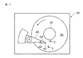
図1−3に磁気ディスク・ドライブ30が示されているが、引用図面における同一の参照数字は、すべての図を通じて同一もしくは類似の部品を示す。ドライブ30は、磁気ディスク34を支持し、回転させるスピンドル32を含む。スピンドル32は、モータ制御装置38によって制御される電動機36によって回転する。組合せ読取り/書込み磁気ヘッド40がスライダ42に取り付けられ、該スライダはサスペンション44及びアクチュエータ・アーム46に支持されている。図3に示されているような大容量直接アクセス記憶装置(DASD)では、複数のディスク、スライダ及びサスペンションを使用することもできる。サスペンション44とアクチュエータ・アーム46は、スライダ42の位置を、磁気ヘッド40が磁気ディスク34の表面と変換関係であるように定める。
For a more detailed understanding of the nature and advantages of the present invention, as well as preferred modes of use, the following detailed description should be read in conjunction with the accompanying drawings. The following describes the best mode currently contemplated for carrying out the invention, but is provided for the purpose of illustrating the general principles of the invention, and is not intended to limit the scope of the invention as claimed herein. It is not intended to limit the concept of.
<Magnetic disk drive>
Although a
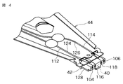
ディスク34が電動機36によって回転している時、スライダはディスク34と空気ベアリング面(ABS)48の間の薄い(典型的には0.05μm)空気のクッション(空気ベアリング)に支えられている。而して磁気ヘッド40は、ディスク34表面上の多数の環状トラックに情報を書き込み、また該トラックから情報を読み取るために使用される。処理回路50は、書き込まれ、読み取られる情報をヘッド40と交換し、磁気ディスク34を回転させるための電動機駆動信号を供給し、スライダを種々異なるトラックに移動させるための制御信号を供給する。図4に、サスペンション44に装着されたスライダ42が示されている。上述の部品類は、図3に示すように1個のフレーム54に装着されていても良い。
As the
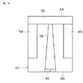
図5は、スライダ42と磁気ヘッド40をABS面から見た図である。スライダは磁気ヘッド40を支える中央レール56と、サイドレール58及び60を持つ。レール56、58及び60は、1本のクロスレール62から伸びる。磁気ディスク34の回転に関しては、クロスレール62はスライダの前縁64に、磁気ヘッド40はスライダの後縁66にある。
〈先行技術の合体式MRヘッド〉
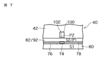
図6は、先行技術の書込みヘッド部分70と読取りヘッド部分72を持ち、読取りヘッド部分にMRセンサ74が用いられている合体式MRヘッド40を側面から見た断面図である。図7は、図6のヘッドのABS面である。センサ74は第1及び第2のギャップ層76、78の間に位置し、ギャップ層は第1及び第2の遮蔽層80及び82の間に位置している。外部磁界に応じて、センサ74の抵抗が変化する。該センサを通して導かれている検知電流Isにより、これらの抵抗変化は電位変化として明示される。これらの電位変化が図3に示されている処理回路50により、リードバック信号として処理される。
FIG. 5 is a view of the
<Prior art merged MR head>
FIG. 6 is a cross-sectional side view of a combined
合体式MRヘッドの先行技術書込みヘッド部分は、第1及び第2の絶縁層86、88の間に位置するコイル層84を含んでいる。コイル層84に起因する第2絶縁層の小さな起伏を除去するために、第3の、ヘッドを平坦化するための絶縁層90を用いても良い。第1、第2及び第3の絶縁層は、この技術分野ではまとめて「絶縁スタック」と呼ばれる。コイル層84と第1、第2及び第3絶縁層86、88及び90は、第1及び第2の磁極片層92及び94の間に位置している。第1及び第2磁極片層92及び94はバックギャップ96で磁気的に結合されており、またABSで書込みギャップ層102で隔てられた第1及び第2の磁極端98及び100を持つ。
The prior art write head portion of the merged MR head includes a
図2及び図4に示されているように、第1及び第2のはんだ接続104、106はセンサ74からのリード導線をサスペンション44上のリード導線112、114に結合し、第3および第4のはんだ接続116、118はコイル84(図8参照)からのリード導線120、122をサスペンション上のリード導線124、126に結合している。図2、4、6及び7に示されているように、磁気ヘッドの傷み易い素子要素を保護するために、磨耗防止層を使用しても良い。合体式MRヘッド40では1個の82/92を用いて、読取りヘッドのための第2遮蔽層、ならびに書込みヘッドのための第1磁極片という二つの機能を果たさせていることに注意されたい。ピギーバック型MRヘッドでは、これらの機能のために別々の2層が使用されている。
As shown in FIGS. 2 and 4, the first and
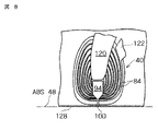
図9に示されているように、第2磁極片層94には磁極端領域と継鉄(ヨーク)領域があり、これら領域の結合部は、第2磁極片層94が、ヘッド内に後退するに従って広がり始める場所であるフレア点130によって定義される。第2磁極端領域はABSからフレア点130まで伸び、ヨーク領域はフレア点130からバックギャップ96(図6参照)まで伸びている。図12には、磁極端領域、ヨーク領域及びフレア点130が、フォトレジストマスク(P2枠)で定義して示してある。
As shown in FIG. 9, the second
図9、12及び13に示されているフレア点130の位置は、書込みヘッドの重要な設計パラメータである。フレア点がヘッドの奥に後退するほど、磁極端100は長くなり、そのため磁気インダクタンスと、磁極端100がコイル層84からの磁束に応じて飽和される可能性が増大する。過去においては、第2磁極端を作る際の製作上の問題があったため。フレア点の位置をABSから10μm未満にまで近づけることは困難であった。
The location of the
書込みヘッドを製作する際のもう一つの重要な設計パラメータはゼロ・スロート・ハイト(ZTH)であり、これはABSの後方で、第1及び第2の磁極片層92及び94が初めて互に分離する場所である。磁界がABSにおけるギャップ層102に到達する以前の磁極片間の磁束損失を軽減するために、ZTHの位置をできる限りABSに近づける(典型的には約1μm以内)ことが重要である。先行技術においては、ZTHの位置をABSに近接させることが、明晰性の良好な第2磁極端100製作上の上述の問題の一因となっていた。
Another important design parameter in the construction of the write head is the zero throat height (ZTH), which is behind the ABS, where the first and second pole piece layers 92 and 94 are separated from each other for the first time. Is a place to be. It is important to position the ZTH as close as possible to the ABS (typically within about 1 μm) to reduce the flux loss between the pole pieces before the magnetic field reaches the
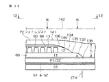
図10は、第2磁極片94(図9参照)製作途中における図9の先行技術ヘッドを示す。図10では、第1、第2及び第3絶縁層86、88、90は、それぞれ先端138、139及び140を終点とする傾斜した表面132、134及び136を持つように示されている。先に述べたように、第1、第2及び第3絶縁層は硬く焼き付けされたフォトレジストであるため、傾斜した表面132、134及び136は光を反射する性質が強い。傾斜した表面132、134及び136は、すべて第2磁極片94の第2磁極端100が形成される磁極端領域に向いている。図10に示されているように、第2磁極片は一部完成したヘッドの上にスピンコートされるフォトレジスト層141を用いて形成される。
FIG. 10 shows the prior art head of FIG. 9 during fabrication of the second pole piece 94 (see FIG. 9). In FIG. 10, the first, second, and third insulating
フォトレジスト層の厚さは、磁極端領域では12μmに達することもあり、第3絶縁層90の上では、典型的には約4.5μmである。第2磁極片94のフレア点130(図9、12及び13に示されている)は絶縁層の傾斜した表面上に位置している故に、マスク142に設けられた第2磁極型の孔(図示されていない)を通された光は、複数の傾斜した表面から前方に、磁極端領域に隣接するフォトレジスト層141中をABS方向に反射されるであろう。このため磁極端領域は、マスク142の孔よりも幅広になる。これは「反射ノッチング」と呼ばれ、図12に示されている。
The thickness of the photoresist layer can reach 12 μm in the pole tip region, and is typically about 4.5 μm on the third insulating
第2磁極片を形成するためのフォトレジストパターンは図12に94'として示されており、これは第2磁極端パターン100'及び第2磁極片継鉄パターン103'を含む。これは「P2枠」と呼ばれる。絶縁層の傾斜した層から、ある入射角で反射された光によるフォトレジスト層141の反射ノッチング(図10参照)は、図12に144及び146で示されている。光線Aはフォトレジストの光イメージング工程中に下方に向けて照射される場合、ある入射角で絶縁スタックから磁極端領域中に反射されても、第2磁極端の反射ノッチングは起こらない。しかし、光イメージング工程における光線Bは、フレア点130よりも後方にある絶縁層の傾斜表面から、ある入射角で意図された磁極端パターン100'の外側、両側領域のフォトレジスト141中に反射される。図12に示されている反射ノッチングを起こすのは、光の反射B及びそれに類似した光の反射である。
The photoresist pattern for forming the second pole piece is shown in FIG. 12 as 94 ', which includes a second pole tip pattern 100' and a second pole piece yoke pattern 103 '. This is called the "P2 frame." The reflection notching (see FIG. 10) of the
第2磁極端94がめっきされ、フォトレジスト層141が除去されると、図9に示されているようにヘッドが完成する。しかしながら、磁極端100の成型状態は悪く、図11に示すように不規則な側壁148、150を示す。更に、フォトレジスト層がノッチングされる結果、第2磁極端100の上部磁極端領域の断面積は磁極端基部(書込みギャップに隣接する)よりも広くなる。この不規則な第2磁極端100が第1磁極端98をノッチングするための切削マスクとして使用されると、第2磁極端の幅広い領域が切削ビームを遮る。そのため、切削プロセスは、第2磁極端の側壁直下にある第1磁極端材料の除去における効果が落ちる。この結果、第1磁極片92のノッチング不完全により、P1ノッチングによる書込みヘッド構造の形成不良が起こる。これら形成不良の磁極端は、隣接トラックへのサイド書込みを引き起こす。
When the
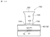
図14は、イオン切削によってP2シード層(図示せず)を除去した後の先行技術による合体式磁気ヘッド150のABS面を示す。イオン切削によってギャップ層102が154及び156で僅かにノッチングされているのを見ることができる。先行技術で第1磁極片層82/92をノッチングする方法の一つは、図15に示されているように、ギャップ層を通して第1磁極片層までイオン切削することである。これにより、第1磁極片層にノッチ159、160ができる。第1磁極片層82/92をノッチングすることは、それによって第2磁極端100と第1磁極片82/92の間のサイド書込みが最小限に抑えられるので望ましい。
FIG. 14 shows the ABS surface of the prior art merged
不幸にして、図15に示すプロセスでは、図15に鎖線で示した第2磁極端頂上部の表面158の消耗が起こる。典型的にはイオン切削は積層された薄膜に対する垂線に対し、ある角度で行われるため、第2磁極端158は、加工される材料が回転している時間の約50%は、ノッチ159及び160形成のための切削を遮蔽する。その結果、第1磁極片82/92は、それぞれノッチ159及び160から離れる方向に伸びる164及び166の領域で過剰切削される。このため、第1磁極片82/92は図15に示すように下向きに傾斜した上面164、166を持つことになり、これは磁界内における第1磁極片82/92の厚さを減らすので望ましくない。場合によっては、第1磁極片82/92の下層にある傷み易い素子要素を露出させ、ヘッドの機能を失わせるおそれがある。ギャップ層102は第1及び第2磁極片のパーマロイ(NiFe)よりも緩慢に切削されるため、第2磁極端100の頂上部158及び第1磁極片82/92の164及び166部分のイオン切削はギャップ層102よりも早くなる。
Unfortunately, the process shown in FIG. 15 results in the depletion of the
図15から、第2磁極端層100の最初の厚さは、イオン切削によって消耗する第2磁極端層の頂上部を補償するために、158における第2磁極端層の最終厚さよりも大きくなければならないことが見て取れる。このため、フォトレジストマスクの厚みを増すことが必要になるが、それによって先に述べた、フォトレジスト層の深さが増すと共に光イメージング工程中における光の散乱が強まる問題も増大する。これは、フォトレジストのパターニング中に明晰度が低下するため、第2磁極端を十分な細さに製作できないことを意味する。また図15は、第2遮蔽層(第1磁極片)82/92を介してギャップ層102に複写されるMRセンサのプロファイルのために、僅かに曲げられていることをも示している。従って、先行技術による合体式MRヘッドには、第2磁極端の反射ノッチング、第1磁極片をノッチングする際の第2磁極端頂上部の損失、及び書込みギャップの湾曲といった欠点が伴うことを見て取れる。これらの問題は、以下に記述する、発明された合体式MRヘッドによって克服される。
From FIG. 15, it can be seen that the initial thickness of the second
図14及び15に示す先行技術のMRヘッドに関するもう一つの問題は、書込みギャップ層102が、第2ギャップ層78及び第2遮蔽/第1磁極片層82/92によるMRセンサのプロファイルの複写によって湾曲していることである。先に論じたように、これが原因で情報がトラックを横断して曲線状に書き込まれ、直線状のMRセンサ74によって不正確に読み取られることになる。
Another problem with the prior art MR head shown in FIGS. 14 and 15 is that the
上に論じたように、DASD(直接アクセス記憶装置)用薄膜ヘッドの先行技術による製造では、長手方向の書込みヘッドが読取りヘッドの下に置かれている米国特許第6,130,809号明細書を除き、書込みヘッドの位置を読取りヘッドの上に置いている。上記特許におけるヘッドは縦方向記録用であり、従ってそのコンセプトにはアスペクト比デマンドが大きい(>20:1)非常に厚い磁極端を製作する必要が伴う。また、磁極に真空蒸着膜を使用することができない。真空蒸着膜のパターニングにはイオン切削を使用する必要があり、イオン切削ではそのようなアスペクト比を得ることができないからである。 As discussed above, prior art fabrication of thin film heads for DASDs (direct access storage devices) involves writing heads except for US Pat. No. 6,130,809, where a longitudinal writing head is located below the read head. Is placed on the read head. The head in the above patent is for longitudinal recording, and the concept therefore requires the fabrication of very thick pole tips with high aspect ratio demands (> 20: 1). Also, a vacuum deposited film cannot be used for the magnetic pole. This is because ion cutting must be used for patterning the vacuum deposited film, and such an aspect ratio cannot be obtained by ion cutting.
図16に、在来のディスク記録システムに使用されているような在来の記録媒体を模式的に示す。この媒体は、該媒体それ自体の面内にあるか面に平行な磁気パルスの記録に用いられる。記録媒体(この例では記録ディスク)は、基本的には、アルミニウムのような適当な非磁性材料の支持基板180と、その上に被着された、適当な樹脂のバインダ中に適当な在来の磁性酸化物を分散させた被膜182を構成要素として含む。
FIG. 16 schematically shows a conventional recording medium as used in a conventional disk recording system. This medium is used for recording magnetic pulses in or parallel to the plane of the medium itself. The recording medium (recording disk in this example) is basically a
図17に、在来の記録/再生ヘッド184(好ましくは薄膜ヘッド)と、図16に示したような在来の記録媒体の間の、作動時の関係を示す。
〈本発明と製作方法〉
図18は、一般的に本発明によって規定される態様における、実質的に記録媒体表面に垂直な磁気パルスの配向を模式的に示したものである。垂直記録のためには、媒体は高い透磁率(好ましくは100よりも大きい)を持つ材料から成る下層192を含み、下層の材料は強磁性もしくはフェリ磁性の、パーマロイ材料、鉄、あるいはそれに類する材料のいずれかで良い。この下層192は、その上にある、好ましくは実質的に下層192の表面に垂直な一軸異方性を持つ被膜194を備えている。
FIG. 17 shows the operating relationship between a conventional recording / reproducing head 184 (preferably a thin film head) and a conventional recording medium as shown in FIG.
<The present invention and manufacturing method>
FIG. 18 schematically illustrates the orientation of a magnetic pulse substantially perpendicular to the surface of a recording medium in an embodiment generally defined by the present invention. For perpendicular recording, the medium includes an
垂直ヘッド190を有する記憶システムの二つの実施形態が図18及び19に示されている(一定の縮尺率で描かれてはいない)。図19に示されている記録媒体は、高透磁率の下層192と、図18に関して上に述べた磁性材料の上塗り層194の両方を含む。但し、これらの層192及び194の両方とも適当な基板196に塗布された形で示されており、該基板はアルミニウムのディスクが望ましいが、ガラス又は合成樹脂のような他の材料を用いることもできる。
Two embodiments of a storage system having a
この構造により、記録ヘッドの磁極間に伸びる磁束の磁力線は、高透磁性の記録媒体下層を持つ記録媒体被膜の外表面に流入し、外表面から流出するループを形成し、磁束の磁力線の大部分を、記録媒体表面に垂直な方向に被膜を通過させ、媒体の磁気的に硬い被膜内に、実質的に媒体表面に垂直な磁化の軸を持つ磁気インパルスの形で情報を記録する。磁束は磁気的に軟らかい下層192によって導かれ、ヘッド190の戻り層(P1)に戻る。
With this structure, the magnetic field lines of the magnetic flux extending between the magnetic poles of the recording head flow into the outer surface of the recording medium coating having the high-permeability recording medium lower layer, and form a loop that flows out of the outer surface. The portion is passed through the coating in a direction perpendicular to the recording medium surface, and information is recorded in the magnetically hard coating of the medium in the form of a magnetic impulse having an axis of magnetization substantially perpendicular to the medium surface. The magnetic flux is guided by the magnetically soft
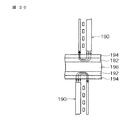
図20は、同様の構造において、基板196が表裏両面に層192ならびに194を担持し、媒体のそれぞれの側に磁性被膜194に隣接して適当な記録ヘッド190が位置している構造を示す。
FIG. 20 shows a similar construction in which a
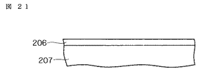
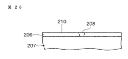
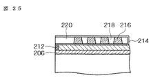
図21−28は、好ましい一実施形態の垂直ヘッドを形成する手順を示したものであり、該ヘッドには、薄膜読取りヘッドの下方に位置する垂直記録薄膜ヘッドが組み込まれている。 FIGS. 21-28 illustrate a procedure for forming a preferred embodiment vertical head, which incorporates a perpendicular recording thin film head located below a thin film read head.
図21に示すように、プローブ/磁極層206を、アルミナのような適当な下地層207の上に、該アルミナ下地層207の上に一様な被膜層を被着(めっき又は真空蒸着により)することによって形成する。好ましい一実施例では、この層の厚さは約0.3μmである。
As shown in FIG. 21, a probe /
図22に描かれているように、加工前のプローブ/磁極層206から1個のプローブ208を、好ましくはイオン切削技術を用いてパターニングする。プローブ/磁極層206は第1層である故、イオン切削によってその下にあるヘッド構造の損傷が起きることはない。このプローブ極端208が、トラックの幅を定義する。プローブ極端208は磁気媒体に、ヘッドに向き合う媒体表面に実質的に垂直配向されている磁束の磁力線を経由して、磁気媒体にデータを書き込む。プローブ極端208の大きさがトラック幅を定義する。この磁束がより集中されているため、在来の縦方向書込みシステムよりもトラック幅が(また、ある程度はビット幅も)はるかに細い記録媒体を使用することができる。また、ディスクの磁性層の厚さも、ある程度ビットのサイズに影響することに注意されたい。プローブ極端208が形成されると、図23に示すように厚いアルミナ210又は他の適当な物質を被着し、化学的・機械的平坦化(CMP)技術によって平坦化してプローブ極層206を完成することができる。
As depicted in FIG. 22, one
図24は、磁束の極208への伝送に寄与する整形層212の付加を示す。より詳しくは、整形層は磁束をプローブ極端に伝送し、系の磁気抵抗(MR)を低下させ、この系は磁束を下方の狭い一点に(漏斗状に)収束させる。整形層はABSに達せず、ごく短い間隔でヘッド内に置かれることが望ましい。この間隔は、ZTHの新しい形態と考えられる。当該技術に精通する者には理解されるであろうが、ABSに近付き、細いプローブの間隔が短くなるほど、ヘッドの効率は高くなる。整形層の材料は、パーマロイ(80/20 NiFe)であることが好ましい。
FIG. 24 illustrates the addition of a
整形層212が作られたら、在来の方法でギャップを充填することができ、ウェハは再度、好ましくはアルミナとCMPを用いて平坦化される。
Once the
図25は、図24のウェハにコイルと絶縁層を加えたものの横断面図である。図25に示されているように、整形層の上面を適当な絶縁体214を用いて絶縁し、コイル216を在来法で、あるいはダマスク象嵌法によって製作される。コイルの一巻の間は、硬く焼き付けられたレジスト218を用いて絶縁することができる。コイル216の前方はABSまで、厚いアルミナ220によって絶縁され得る。この構造はもう一度平坦化されてその上にP1層が形成されるべき、平坦な表面が作られる。
FIG. 25 is a cross-sectional view of the wafer of FIG. 24 with a coil and an insulating layer added. As shown in FIG. 25, the top surface of the shaping layer is insulated using a
図26は、P1層230を付加した後のウェハを描いたものである。P1層230はABSに達しており、書込みヘッドの磁束がディスクの下層を離れた後の戻り経路として機能する。P1層230が作られたら、在来の方法でギャップを充填することができ、ウェハは再度、好ましくはアルミナとCMPを用いて平坦化される。
FIG. 26 illustrates the wafer after the
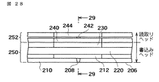
図27は、ウェハに第1遮蔽(S1)層240を加えた状態を示す。S1層240は典型的にはサイズ依存性がほとんど無い、きわめて製作の簡単な層であるため、完全に平坦でない(CMP平坦化後であっても)ウェハ上にでも製作できることに注意されたい。それ故、P1層を完全に平坦化する必要はない。標準型の読取りヘッド(GMR又はトンネル)242(図28参照)の製作ができるように更にもう一度ウェハを平坦化し、第2ギャップを堆積した後に第2遮蔽層(S2)244(図28参照)を製作する。
FIG. 27 shows a state where the first shielding (S1)
図28−29は好ましい実施形態における完成した構造を示すものであり、この構造では垂直記録用薄膜(書込み)ヘッド250は薄膜読取りヘッド252の下に位置している。垂直記録用薄膜ヘッド250を薄膜読取りヘッド252の下に組み合わせるため、書込みヘッド250が最初に製作されるという固有の利点が得られる。書込みヘッド250は高温度で加工する必要があるため、もし読取りヘッドが先に製作されたならば、その材料を不安定にする原因となるであろう。書込み用の磁極/プローブが最初に製作され、かつそれが最大の労力を要する構造であるため、その製作に関連する問題が生じた場合には、ウェハを最小限のコスト損失で再加工したり、不合格にすることができるであろう。もし磁極/プローブが最後に作られるならば、完成寸前のウェハが不合格とされ、コスト損失がはるかに大きくなる可能性があり得る。
FIGS. 28-29 show the completed structure in the preferred embodiment, in which the perpendicular recording thin film (write)
また、開示された垂直構造は、きわめてすぐれたヘッド性能、良好な熱の消散性、及びごく薄い書込み用磁極しか必要としないことを兼備している。整形層はプローブ磁極に磁束を収束させるので、必要なコイルの数が減少する。従って、本発明の各実施形態は基本的にフリンジの無いプロセスをもたらす垂直記録を用いるために、トラック間隔を狭めることが可能になる。 Also, the disclosed vertical structure combines very good head performance, good heat dissipation, and the need for very thin write poles. The shaping layer focuses the magnetic flux on the probe poles, thus reducing the number of coils required. Thus, embodiments of the present invention can reduce the track spacing because they use perpendicular recording, which essentially results in a fringe-free process.
上に述べたように、効率を高めるために、ABSと閉鎖バックギャップの間の間隔がきわめて短い誘導ヘッドが設計されているのが現在の趨勢である。コイルをABSにごく近接させ、かつコイルのピッチをきわめて小さくすることで、そのような微小範囲で熱が発散すると熱による突出が生じ、ディスクとヘッドの間の磁気分離が望ましくないほどに増大する。 As noted above, the current trend is to design guidance heads with a very short distance between the ABS and the closed back gap to increase efficiency. By placing the coil in close proximity to the ABS and making the coil pitch very small, heat dissipation in such a small area causes thermal protrusion, which undesirably increases magnetic separation between the disk and head .
書込みヘッドを最初の位置(したがって熱を吸収するスライダの近傍)に置くことによって熱の消散が改善され、それによって突出の問題を軽減することが助けられる。更に、米国特許第6,259,583号明細書のヘッドでは、コイルをABSから4μm以下にまで近付けるためにペデスタル状の構造を用いているが、本発明の好ましい実施形態ではペデスタルは不必要である。 Placing the write head in its initial position (and thus near the heat absorbing slider) improves heat dissipation, thereby helping to reduce protrusion problems. Further, although the head of US Pat. No. 6,259,583 uses a pedestal-like structure to bring the coil closer to 4 μm or less from ABS, the preferred embodiment of the present invention does not require a pedestal.
在来のヘッドでは、P1層及びP2層の幅は開示されている各実施形態の相当する層よりも広く、そのためサイド書込みが発生する。在来のヘッドから発生する周辺磁界は垂直記録ヘッドに比べて最大40%も広い。上に述べたように、好ましい実施形態では、記録ヘッドにペデスタルは不要である。垂直記録においては、磁束はディスク内にジャンプし、ディスクがペデスタルとして働き、大きなP1層に磁束を戻す。ペデスタルを除去することによって磁束は集中され、ヘッドを戻り層として利用させることによって在来ヘッドの諸問題(周辺磁界、熱、突出、等)がほとんど完全に回避されるので、高い分解能が保証される。 In a conventional head, the widths of the P1 and P2 layers are wider than the corresponding layers in each of the disclosed embodiments, so that side writing occurs. The peripheral magnetic field generated by a conventional head is up to 40% wider than that of a perpendicular recording head. As mentioned above, in the preferred embodiment, no pedestal is required for the printhead. In perpendicular recording, the magnetic flux jumps into the disk and the disk acts as a pedestal, returning the magnetic flux to the large P1 layer. The removal of the pedestal concentrates the magnetic flux, and the use of the head as a return layer almost completely avoids the problems of the conventional head (peripheral magnetic field, heat, protrusion, etc.), thus ensuring high resolution. You.
読取りヘッドは現在なお熱を吸収するスライダから隔たっているが、その下にある金属製構造部分の組合せが、優れた熱吸収要素として働く。また、書込みヘッドを最初に製作することによって、その製作に要する高温度加工プロセスが読取りヘッドに影響することも皆無になる。書込みヘッドの比較的労力を要する層(プローブ極)がK5層又はK3層よりも大きいという事実は、整合ターゲットの分解能が向上するであろうことを意味する。 Although the read head is still remote from the heat absorbing slider, the combination of the underlying metal structures serves as an excellent heat absorbing element. Also, by first fabricating the write head, the high temperature processing required for its fabrication does not affect the read head. The fact that the relatively labor intensive layer (probe pole) of the write head is larger than the K5 or K3 layer means that the resolution of the alignment target will be improved.
以上、種々の実施形態について記述したが、それらは単に例示のためのものであり、限定ではないことを理解されたい。従って、好ましい実施形態の幅と範囲は、上に述べた典型的実施形態のいずれによっても全く制限されず、先に記載されている特許請求範囲及びそれらの同等物によってのみ定義される。 While various embodiments have been described above, it should be understood that they have been presented by way of example only, and not limitation. Accordingly, the breadth and scope of the preferred embodiment is not at all limited by any of the above-described exemplary embodiments, but is defined only by the claims set forth above and equivalents thereof.
30:磁気ディスク・ドライブ、
32:スピンドル、
34:磁気ディスク、
36:電動機、
38:モータ制御装置、
40:読取り/書込み磁気ヘッド、
42:スライダ、
44:サスペンション、
46:アクチュエータ・アーム、
48:空気ベアリング面(ABS)、
50:処理回路、
190:垂直ヘッド、
192:下層、
194:上塗り層、
196:基板、
206:プローブ/磁極層、
207:下地層、
208:プローブ、
212:整形層、
214:絶縁体、
218:レジスト、
220:アルミナ、
230:第1磁極片(P1層)、
240:第1遮蔽層(S1)、
242:読取りヘッド(GMR又はTMR)、
244:第2遮蔽層(S2)、
250:垂直記録用薄膜(書込み)ヘッド、
252:薄膜読取りヘッド。
30: Magnetic disk drive,
32: spindle,
34: Magnetic disk,
36: Electric motor,
38: Motor control device,
40: read / write magnetic head,
42: Slider,
44: Suspension,
46: Actuator arm,
48: Air bearing surface (ABS),
50: Processing circuit,
190: vertical head,
192: Lower layer,
194: Topcoat layer,
196: substrate,
206: probe / pole layer,
207: Underlayer,
208: Probe,
212: shaping layer,
214: Insulator,
218: resist,
220: alumina,
230: 1st pole piece (P1 layer),
240: first shielding layer (S1)
242: read head (GMR or TMR),
244: second shielding layer (S2),
250: Thin film (write) head for perpendicular recording
252: Thin film read head.
Claims (29)
第1磁極端を有する第1磁極片と、
磁束を放射するためのプローブ極端を有するプローブ極片と、
前記第1磁極片とプローブ極片の間に位置する絶縁スタックと、
該絶縁スタック中に埋め込まれた少なくとも1個の書込みコイルと、
を含む書込みヘッド部分と、
該書込みヘッド部分の次に製作され、当該書込みヘッド部分に結合される読取りヘッド部分と、
を有することを特徴とする垂直記録・読出し用磁気ヘッド構造。 A write head portion for writing data to a magnetic medium via magnetic field lines of magnetic flux oriented substantially perpendicular to the surface of the facing magnetic medium;
A first pole piece having a first pole tip;
A probe pole piece having a probe extreme for emitting magnetic flux,
An insulating stack located between the first pole piece and the probe pole piece;
At least one write coil embedded in the insulating stack;
A write head portion comprising:
A read head portion fabricated next to the write head portion and coupled to the write head portion;
A perpendicular recording / reading magnetic head structure comprising:
第1磁極端を有する第1磁極片と、
磁束を放射するためのプローブ極端を有するプローブ極片と、
前記第1極片とプローブ極片の間に位置する絶縁スタックと、
該絶縁スタック中に埋め込まれた少なくとも1個の書込みコイルと、
前記プローブ極片と絶縁スタックの間に位置し、磁束を前記プローブ極端に集中せしめるための整形層と、
を含む薄膜書込みヘッド部分と、
該書込みヘッド部分の次に製作され、当該書込みヘッド部分に結合される薄膜読取りヘッド部分と、
を有することを特徴とする垂直記録・読出し用磁気ヘッド構造。 A thin-film write head portion for writing data to a magnetic medium via magnetic field lines of magnetic flux oriented substantially perpendicular to an opposing surface of the medium;
A first pole piece having a first pole tip;
A probe pole piece having a probe extreme for emitting magnetic flux,
An insulating stack located between the first pole piece and the probe pole piece;
At least one write coil embedded in the insulating stack;
A shaping layer located between the probe pole piece and the insulation stack to concentrate magnetic flux to the probe extremes;
A thin film write head portion comprising:
A thin film read head portion fabricated next to the write head portion and coupled to the write head portion;
A perpendicular recording / reading magnetic head structure comprising:
前記プローブ極片の上に、絶縁スタックと、該絶縁スタック中に埋め込まれた書込みコイルを製作する工程と、
第2磁極端を持つ第2磁極片を前記絶縁スタックの上に製作する工程と、
該第2磁極片の上に読取りヘッド部分を製作する工程と、
を含むことを特徴とする垂直記録・読出し用磁気ヘッドを製作する方法。 Fabricating a probe pole piece having a probe pole for writing data to a magnetic medium via magnetic flux lines oriented substantially perpendicular to the surface of the magnetic medium facing the write head portion; ,
Fabricating an insulating stack on the probe pole piece and a write coil embedded in the insulating stack;
Fabricating a second pole piece having a second pole tip on the insulating stack;
Fabricating a read head portion on said second pole piece;
A method for manufacturing a perpendicular recording / reading magnetic head, comprising:
該磁気媒体からの読み取り、及び該媒体への書き込みを行うための1個以上のヘッドと、それぞれのヘッドは、
向き合っている前記磁気媒体の表面に対して実質的に垂直に配向されている磁束の磁力線を経由して該媒体にデータを書き込む書込みヘッド部分であって、
第1磁極端を有する第1磁極片と、
磁束を放射するためのプローブ極端を有するプローブ極片と、
前記第1極片とプローブ極片の間に位置する絶縁スタックと、
該絶縁スタック中に埋め込まれた1個以上の書込みコイルと、
を有する書込みヘッド部分と、
前記書込みヘッド部分の次に製作され、該書込みヘッド部分に結合される読取りヘッド部分と、を有し、
前記ヘッドを担持するためのスライダと、
前記ヘッドの動作を制御するために該ヘッドに結合されている制御ユニットと、
を有することを特徴とする磁気記憶システム。 A magnetic medium,
One or more heads for reading from and writing to the magnetic medium, and each head includes:
A write head portion for writing data to a magnetic medium via magnetic field lines of magnetic flux oriented substantially perpendicular to the facing magnetic medium surface,
A first pole piece having a first pole tip;
A probe pole piece having a probe extreme for emitting magnetic flux,
An insulating stack located between the first pole piece and the probe pole piece;
One or more write coils embedded in the insulating stack;
A write head portion having
A read head portion fabricated next to the write head portion and coupled to the write head portion;
A slider for carrying the head,
A control unit coupled to the head for controlling operation of the head;
A magnetic storage system comprising:
The magnetic medium has a first magnetically hard layer facing the at least one head and a second magnetically soft layer behind the first layer. Item 25. The storage system according to item 24.
Applications Claiming Priority (1)
| Application Number | Priority Date | Filing Date | Title |
|---|---|---|---|
| US10/431,489 US7969683B2 (en) | 2003-05-06 | 2003-05-06 | Write first design for a perpendicular thin film head |
Publications (2)
| Publication Number | Publication Date |
|---|---|
| JP2004335086A true JP2004335086A (en) | 2004-11-25 |
| JP2004335086A5 JP2004335086A5 (en) | 2007-06-14 |
Family
ID=33416466
Family Applications (1)
| Application Number | Title | Priority Date | Filing Date |
|---|---|---|---|
| JP2004129406A Pending JP2004335086A (en) | 2003-05-06 | 2004-04-26 | First writing structure for perpendicular thin film head |
Country Status (3)
| Country | Link |
|---|---|
| US (1) | US7969683B2 (en) |
| JP (1) | JP2004335086A (en) |
| CN (1) | CN1551110A (en) |
Families Citing this family (5)
| Publication number | Priority date | Publication date | Assignee | Title |
|---|---|---|---|---|
| US7170713B2 (en) * | 2002-08-08 | 2007-01-30 | Hitachi Global Storage Technologies Netherlands B.V. | Heat sink for a magnetic recording head |
| US7068453B2 (en) * | 2004-02-27 | 2006-06-27 | Hitachi Global Storage Technologies Netherlands B.V. | Thermally-assisted perpendicular magnetic recording system and head |
| KR100682943B1 (en) * | 2005-03-24 | 2007-02-15 | 삼성전자주식회사 | Magnetic writing head, magnetic writing device comprising the same and manufacturing method of the magnetic writing head |
| JP2006294163A (en) * | 2005-04-13 | 2006-10-26 | Hitachi Global Storage Technologies Netherlands Bv | Disk drive |
| WO2007074522A1 (en) * | 2005-12-27 | 2007-07-05 | Fujitsu Limited | Magnetic head and disc device |
Family Cites Families (28)
| Publication number | Priority date | Publication date | Assignee | Title |
|---|---|---|---|---|
| US4277809A (en) | 1979-09-26 | 1981-07-07 | Memorex Corporation | Apparatus for recording magnetic impulses perpendicular to the surface of a recording medium |
| JPS60177420A (en) | 1984-02-23 | 1985-09-11 | Nec Corp | Composite type thin film magnetic head and its production |
| JPH01155510A (en) | 1987-12-14 | 1989-06-19 | Hitachi Ltd | Magnetic head for vertical magnetic recording and reproduction |
| US5073836A (en) | 1989-10-05 | 1991-12-17 | Hewlett-Packard Company | Single pole write and a differential magneto-resistive read for perpendicular recording |
| US6320725B1 (en) | 1989-11-27 | 2001-11-20 | Censtor Corporation | Hard disk drive having ring head with predominantly perpendicular media fields |
| JPH04216311A (en) | 1990-12-18 | 1992-08-06 | Fujitsu Ltd | Magnetic head |
| JP2850921B2 (en) | 1991-03-15 | 1999-01-27 | 富士通株式会社 | Magnetic recording / reproducing device |
| US5455730A (en) | 1993-02-18 | 1995-10-03 | International Business Machines Corporation | Contact magnetic recording disk file with a magnetoresistive read sensor |
| US5486967A (en) | 1993-03-15 | 1996-01-23 | Kabushiki Kaisha Toshiba | Magnetic disk memory system |
| JPH06295418A (en) | 1993-04-09 | 1994-10-21 | Nec Corp | Combined magnetic head and magnetic recording and reproducing device |
| US5668689A (en) | 1994-03-03 | 1997-09-16 | Seagate Technology, Inc. | Inverted magnetoresistive head |
| JPH0922512A (en) | 1995-07-05 | 1997-01-21 | Sony Corp | Composite thin film magnetic head and its production |
| US5710683A (en) | 1996-04-18 | 1998-01-20 | Storage Technology Corporation | Thin film tape head with substrate for reduced pole-tip recession |
| US5822153A (en) | 1997-01-03 | 1998-10-13 | Censtor Corp. | Hard disk drive having contact write and recessed magnetorestive read head |
| US5901432A (en) | 1997-12-24 | 1999-05-11 | International Business Machines Corporation | Method for making a thin film inductive write head having a pedestal pole tip and an electroplated gap |
| JP3371081B2 (en) | 1997-12-26 | 2003-01-27 | ティーディーケイ株式会社 | Composite thin-film magnetic head, method of manufacturing composite thin-film magnetic head, and common unit for composite thin-film magnetic head used in manufacturing method |
| US6301076B1 (en) * | 1998-03-20 | 2001-10-09 | Seagate Technology Llc | Narrow track inductive write head having a two-piece pole |
| US6130809A (en) | 1998-04-10 | 2000-10-10 | International Business Machines Corporation | Write head before read head constructed merged magnetic head with track width and zero throat height defined by first pole tip |
| US6172848B1 (en) | 1998-04-10 | 2001-01-09 | International Business Machines Corporation | Write head with self aligned pedestal shaped pole tips that are separated by a zero throat height defining layer |
| US6259583B1 (en) | 1998-09-16 | 2001-07-10 | International Business Machines, Corporation | Laminated yoke head with a domain control element |
| JP2001101612A (en) | 1999-09-30 | 2001-04-13 | Toshiba Corp | Magnetic head and magnetic recorder |
| JP3866512B2 (en) * | 2000-12-26 | 2007-01-10 | アルプス電気株式会社 | Method for manufacturing perpendicular magnetic recording head |
| JP3593312B2 (en) | 2000-12-26 | 2004-11-24 | アルプス電気株式会社 | Perpendicular magnetic recording head and method of manufacturing the same |
| US6954340B2 (en) * | 2001-05-23 | 2005-10-11 | Seagate Technology Llc | Perpendicular magnetic recording head with nonmagnetic write gap greater than twice side shield gap distance |
| JP2003016608A (en) | 2001-06-28 | 2003-01-17 | Tdk Corp | Thin film magnetic head and its manufacturing method |
| JP2003217103A (en) * | 2002-01-18 | 2003-07-31 | Fuji Xerox Co Ltd | Method for manufacturing magnetic head, magnetic head and magnetic disk device |
| US6757141B2 (en) * | 2002-01-18 | 2004-06-29 | Hitachi Global Storage Technologies Netherlands B.V. | Perpendicular recording write head with a ferromagnetic shaping layer |
| US7119988B2 (en) * | 2003-04-01 | 2006-10-10 | Hitachi Global Storage Technologies Netherlands, B.V. | Perpendicular magnetic head having modified shaping layer for direct plating of magnetic pole piece |
-
2003
- 2003-05-06 US US10/431,489 patent/US7969683B2/en not_active Expired - Fee Related
-
2004
- 2004-04-26 JP JP2004129406A patent/JP2004335086A/en active Pending
- 2004-04-27 CN CNA2004100386056A patent/CN1551110A/en active Pending
Also Published As
| Publication number | Publication date |
|---|---|
| US7969683B2 (en) | 2011-06-28 |
| US20040223257A1 (en) | 2004-11-11 |
| CN1551110A (en) | 2004-12-01 |
Similar Documents
| Publication | Publication Date | Title |
|---|---|---|
| US10811034B1 (en) | Heat sink structure for microwave-assisted magnetic recording (MAMR) head | |
| KR100420540B1 (en) | Magnetic write head | |
| US7154707B2 (en) | Thin film magnetic head and magnetic recording apparatus | |
| US7718218B2 (en) | Thin-film magnetic head, method of manufacturing the same, head Gimbal assembly, and hard disk drive | |
| US7580222B2 (en) | Thin-film magnetic head, a head gimbal assembly and hard disk drive | |
| US7436633B2 (en) | Thin-film magnetic head, head gimbal assembly and hard disk system | |
| US6934128B2 (en) | Magnetic head and magnetic disk drive | |
| US7142392B2 (en) | Thin film head, producing method thereof and magnetic disk apparatus | |
| US7921544B2 (en) | Method of manufacturing a thin film magnetic head structure | |
| US20060117556A1 (en) | Thin film magnetic head and method of manufacturing the same | |
| US20070268627A1 (en) | Method for manufacturing a self-aligned, notched trailing shield for perpendicular recording | |
| US20040070872A1 (en) | High data rate write head | |
| JP2005050510A (en) | Perpendicular recording magnetic head with write shield magnetically coupled to first pole piece | |
| JP2007128581A (en) | Magnetic head and its manufacturing method | |
| KR19980032173A (en) | A recording head having a yoke which is recessed and stitched on a flat portion of an insulating layer defining a zero- | |
| JPH10334409A (en) | Thin film magnetic head | |
| US11043232B1 (en) | Spin torque reversal assisted magnetic recording (STRAMR) device having a width substantially equal to that of a traililng shield | |
| JP2007294088A (en) | Magnetic write head which makes projection induced thermally decrease, and its manufacturing method | |
| US6757134B2 (en) | High density thin film inductive head structure having a planarized coil insulation structure including hard baked photoresist and a filler material | |
| US6487042B2 (en) | Thin-film magnetic head and magnetic storage apparatus using the same | |
| US10770103B1 (en) | Perpendicular magnetic recording (PMR) writer with narrow high moment trailing shield | |
| JP2004335086A (en) | First writing structure for perpendicular thin film head | |
| JP3981880B2 (en) | Magnetic recording head and magnetic recording apparatus | |
| JP2002042307A (en) | Inductive thin-film magnetic head and magnetic disk device | |
| US20030067721A1 (en) | First pole piece with frequency dependent variable effective throat height |
Legal Events
| Date | Code | Title | Description |
|---|---|---|---|
| A521 | Request for written amendment filed |
Free format text: JAPANESE INTERMEDIATE CODE: A523 Effective date: 20070419 |
|
| A621 | Written request for application examination |
Free format text: JAPANESE INTERMEDIATE CODE: A621 Effective date: 20070419 |
|
| RD02 | Notification of acceptance of power of attorney |
Free format text: JAPANESE INTERMEDIATE CODE: A7422 Effective date: 20070419 |
|
| A977 | Report on retrieval |
Free format text: JAPANESE INTERMEDIATE CODE: A971007 Effective date: 20081126 |
|
| A131 | Notification of reasons for refusal |
Free format text: JAPANESE INTERMEDIATE CODE: A131 Effective date: 20081209 |
|
| A02 | Decision of refusal |
Free format text: JAPANESE INTERMEDIATE CODE: A02 Effective date: 20090512 |
