JP2004334487A - Image input device and image input method - Google Patents
Image input device and image input method Download PDFInfo
- Publication number
- JP2004334487A JP2004334487A JP2003128971A JP2003128971A JP2004334487A JP 2004334487 A JP2004334487 A JP 2004334487A JP 2003128971 A JP2003128971 A JP 2003128971A JP 2003128971 A JP2003128971 A JP 2003128971A JP 2004334487 A JP2004334487 A JP 2004334487A
- Authority
- JP
- Japan
- Prior art keywords
- touch pen
- image
- input device
- display
- cable
- Prior art date
- Legal status (The legal status is an assumption and is not a legal conclusion. Google has not performed a legal analysis and makes no representation as to the accuracy of the status listed.)
- Pending
Links
Images


Landscapes
- Cameras Adapted For Combination With Other Photographic Or Optical Apparatuses (AREA)
- Studio Devices (AREA)
Abstract
Description
【0001】
【発明の属する技術分野】
この発明は画像入力装置および画像入力方法に関し、特に、操作性よく入力操作を行なうことのできる画像入力装置および画像入力方法に関する。
【0002】
【従来の技術】
ディスプレイをタッチして情報を入力する入力装置としてタッチペンが広く知られている。このようなタッチペンを含む入力装置は、たとえば特許文献1などに開示されているように、対価の受領を確認して被写体の撮影画像を入力し、入力画像を印刷して提供する写真自動販売機(いわゆるプリクラなどと言われる)や、デジタルカメラや撮影機能付きの携帯電話などから画像を入力し、入力画像を画像処理して印刷して提供する装置などの画像入力装置に、指示情報や画像を入力するために取付けられている。
【0003】
タッチペンはディスプレイと一対となって入力装置を構成し、ケーブルで本体の装置に接続されている。そのケーブルの根元は、図21に示されるように、たとえば画像入力装置などの本体装置に、ユーザのタッチペン操作によって引抜かれないように固定されて取付けられている。
【0004】
【特許文献1】
特開2002−10249号公報
【0005】
【発明が解決しようとする課題】
しかしながら、従来からなされているように、タッチペンに接続されているケーブルの根元を単に本体装置に取付けているだけでは、タッチペンを手にして入力操作を行なう際にケーブルの重みがタッチペンにかかり、ユーザの手に負担がかかり、入力操作に疲れて不快感を感じるなどの問題があった。この問題は、特に、ケーブルの取付け位置が、タッチペンを手にして入力操作を行なうユーザの手の位置よりも上にある場合に発生し、一般的な画像入力装置においてもこういった問題が発生している。
【0006】
また、タッチペンを用いて入力操作を行なう際に、タッチペンと本体装置とを接続しているケーブルが邪魔になって、入力操作を行ない難い場合があるという問題があった。
【0007】
本発明はこのような問題に鑑みてなされたものであって、操作性よく入力操作を行なうことのできる画像入力装置および画像入力方法を提供することを目的とする。
【0008】
【課題を解決するための手段】
上記目的を達成するために、本発明のある局面に従うと、画像入力装置は、ディスプレイにタッチして情報を入力するためのタッチペンを含む入力装置を備える画像入力装置であって、タッチペンに付随するケーブルを当該画像入力装置の所定の面に接合する部分であるタッチペン取付部が、ケーブルと上述の所定の面とが所定の角度となるようにケーブルを支持する構造であることを特徴とする。
【0009】
また、タッチペン取付部の構造は、所定強度以上の強度がかかると、強度のかかった方向に撓む弾性のある部材でケーブルを支持する構造であることが望ましい。
【0010】
また、タッチペン取付部の構造は、タッチペン取付部とディスプレイとの距離以下の長さの部材でケーブルを支持する構造であることが望ましい。
【0011】
さらに、上述の部材の、当該画像入力装置の所定の面に接合されている側と反対の端部は、ケーブルを傷つけ難い構造となっていることが望ましい。
【0012】
また、タッチペン取付部を含む所定の面はディスプレイを含む面であり、所定の面が水平面から所定の角度であることが望ましい。
【0013】
さらに、タッチペン取付部は、ディスプレイの横方向の中心線よりも上の位置にあることが望ましい。
【0014】
あるいは、タッチペン取付部を含む所定の面は、ディスプレイを含む面とは異なる面であることが望ましい。
【0015】
本発明の他の局面に従うと、画像入力装置は、ディスプレイにタッチして情報を入力するためのタッチペンを含む入力装置を備える画像入力装置であって、タッチペンに付随するケーブルが、ディスプレイを含む面とは異なる面に接合されることを特徴とする。
【0016】
本発明のさらに他の局面に従うと、画像入力方法は、上述の画像入力装置において画像入力を行なう方法であって、第1の画像を取得する第1画像取得ステップと、上述のタッチペンを含む入力装置を用いて、第2の画像を指定する第2画像指定ステップと、入力装置を用いて、第1の画像と第2の画像とに対する処理に関する指示を入力する指示入力ステップと、指示に基づいて、第1の画像と第2の画像とを画像処理する画像処理ステップとを備える。
【0017】
【発明の実施の形態】
以下に、図面を参照しつつ、本発明の実施の形態について説明する。以下の説明では、同一の部品および構成要素には同一の符号を付してある。それらの名称および機能も同じである。したがってそれらについての詳細な説明は繰返さない。
【0018】
本実施の形態においては、本発明にかかる画像入力装置が写真自動販売機であるものとして説明を行なうが、画像入力装置は写真自動販売機に限定されるものではなく、画像を入力し、ユーザからの指示を受付けて入力された画像に対して画像処理や印刷処理などの処理を行なう他の装置であってもよい。
【0019】
図1は、本実施の形態における写真自動販売機の外観の具体例を示す図である。写真自動販売機は、大きく分けて撮影操作を行なう側の面と、撮影後の画像にいわゆるお絵描きと言われる、画像やテキストの入力であるお絵描き操作を行なう側の面とを対にして備えており、図1は、撮影操作を行なう面から写真自動販売機を見たときの外観の具体例を示す図である。
【0020】
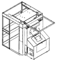
本実施の形態における写真自動販売機は、パーソナルコンピュータ(以下、PCという)101やプリンタ12、制御部102(基盤)(共に図3参照)などの各種機器類を収める筐体1と、筐体1と共に撮影ブース4(図2参照)を形成するパネルとフレーム材とを含む。図1においては、説明のために、パネルとフレーム材とを外した状態である筐体1の撮影操作側が示されている。
【0021】
このような写真自動販売機において、被写体であるユーザは、筐体1、パネルおよびフレーム材にて構成される撮影スペースである撮影ブース4内に入り、筐体1に相対する向きで撮影を行なう。なお、以降の説明において、便宜上、筐体1の撮影操作側の面を正面とし、お絵描き操作側の面を背面とする。また、本実施の形態においては、被写体がユーザ(人)であるものとして説明を行なうが、被写体はユーザに限定されず、その他の物体であってもかまわない。また、被写体であるユーザは、1人であってもよいし、複数であってもよい。
【0022】
図1を参照して、写真自動販売機の筐体1の正面には、カメラ21と、カメラ21で撮影された画像やデモ画面、撮影中の操作手順、ユーザへのアナウンスなどを表示するモニタ22と、デモンストレーション(以下、「デモ」と略す)音声や、BGM、操作方法などのアナウンスを出力する図示されないスピーカ23aと、対価である硬貨を投入するためのコイン投入口26と、前面のメンテナンスなどを行なうためのフロントドア28とが備えられる。
【0023】
また、筐体1のカメラ21の周囲には、蛍光灯やフラッシュなどを内蔵し、被写体の照明を行なうための照明ボックス18a〜18cが備えられている。また、筐体1の前面には、ユーザからの操作を入力する操作ボタン51が備えられている。
【0024】
モニタ22は、当該写真自動販売機で実行されるプレイ方法(コース)の選択などの選択肢を表示する。ユーザは、操作ボタン51を押下して選択を行なう。操作ボタン51は、図1に示されるように、上下に選択肢の選択を移動させるカーソルボタンと、当該選択を決定する決定ボタンと、当該決定をキャンセルするキャンセルボタンとを含んで構成される。また、操作ボタン51に同じ機能を備える複数のボタンが含まれる場合、たとえば図1に示されるように上下に移動させるカーソルボタンが複数組ある場合、それらは複数のユーザから同時に操作入力を受付けるものであってもよいし、モニタ22の右側に表示している選択肢についての選択を右側の組の操作ボタンから受付けて、左側に表示している選択肢についての選択を左側の組の操作ボタンから受付けてもよい。
【0025】
カメラ21で撮影された画像はリアルタイムにモニタ22に表示され、これによりユーザは撮影により得られる画像を視覚確認することができる。
【0026】
カメラ21としては、一般にデジタルカメラが用いられる。一般的なデジタルカメラで設定できる項目(たとえばシャッタスピード、絞り値、露出補正、ホワイトバランスなど)の変更や、撮影タイミングは、PC101(図3参照)から指示される。
【0027】
さらに、筐体1の上面には、筐体1内部の熱を逃がすためのファンや、外部装置への画像の配信、リモートメンテナンスなどの、外部装置との通信を行なうときにケーブルを差込むためのLAN(Local Area Network)ケーブル差込口などが備えられていることが好ましい。なお、このようなファンは、筐体1内部の熱を逃がす目的で備えられるものであるため、筐体1の上面に限定されず、熱を発生しやすい機器類の近傍などの他の場所に備えられても、また複数備えられてもかまわない。また、LANケーブル差込口が備えられる位置も、ケーブルの配線の取回しが容易な位置であれば筐体1の上面に限定されない。
【0028】
また、撮影ブース4を構成する図示されないパネルが木製である場合には、パネルは左側面、右側面、背面、および天井面などに大きく分割される。さらに、背面のパネルは大きいことから、上下または左右に2枚に分割されている場合がある。また、撮影ブース4の内部となるパネルの内面は、照明の反射による間接光を得ることを目的とする場合は白色、逆に光を吸収させたいときは黒色、クロマキー合成を行なう目的のときは青色などの色彩が施される。すなわち、パネルの内面の色は、写真自動販売機においてどのような撮影を行なうかによって、設計開発時に適宜選ばれる。また、パネルは、布またはビニール材等で代替することもでき、その場合には、フレーム材にたるみなく張られた状態で固定される。
【0029】
また、撮影ブース4内には図示されない背景カーテンが配備され、撮影時の背景として用いられる。背景の色によって、被写体の写り方、特に色調が変ってくるため、さまざまな色、柄のカーテンが複数枚用意されている。また、背景カーテンが備えられていなくても構わない。さらに、背景カーテンは、巻上げ式、引出し方式など、ユーザの手動操作によりセットされてもよいし、操作ボタン51等を操作することで自動でセットされてもよい。また、背景カーテンは、さまざまな種類が配備されることで、撮影における遊びの要素ともなり得る。
【0030】
また、ユーザが撮影ブース4内に出入りできるように写真自動販売機の側面は開けられているが、他の人に撮影している場面を見られたくないなどの利用者の気持ちに配慮するため、また外部光を遮断するためなどの目的で、その側面に図示されないサイドカーテンが備えられている。なお、撮影ブースへの出入りが一方の側面のみである場合には、その側面にのみサイドカーテンが備えられる。また、両側面から出入りできる場合には、両側面にサイドカーテンが備えられていてもよい。ユーザは、撮影を行なう際には、このサイドカーテンを開けて撮影ブース4に入り、撮影時はサイドカーテンを閉める。なお、サイドカーテンの裏面(撮影ブース4の内側)の色等は、背景カーテンやパネル内面と同様の理由で適宜選ばれる。
【0031】
次に、図2に、写真自動販売機を筐体1の背面(お絵描き操作を行なう面)から見たときの外観の具体例を示す。
【0032】
図2を参照して、写真自動販売機の筐体1の背面には、撮影により得られた画像を表示し、画像の編集を受付けるディスプレイ13と、画像入力を行なうためのタッチペン14と、ユーザに対し音楽や操作方法の説明などを音声で出力するスピーカ23bとが備えられる。
【0033】
ディスプレイ13は撮影後の画像を表示する。また、ユーザより、撮影により得られた画像に対してタッチペン14を用いた編集入力(落書き)を受付ける。
【0034】
タッチペン14は、ペン形状の入力装置であって、ディスプレイ13にタッチすることで、背景、スタンプ、フレームなどの画像や文字の入力、または使用する項目(ボタン)の選択、操作の選択などの入力をすることができる。タッチペン14は、写真自動販売機に1本備えられていてもよいし、図2に示されるように複数備えられ、同時に複数のユーザからの入力操作を可能にしてもよい。なお、タッチペン14でディスプレイ13をタッチして画像などを入力する処理は、本発明の本質であるため、後に詳細に説明する。
【0035】
さらに図2を参照して、写真自動販売機の筐体1の側面には、箱型の形状を奏したプリント取出口9が備えられる。筐体1の内部にはプリンタ12が備えられ、プリンタ12でプリントされた写真は排出され、ここに落とされる。
【0036】
プリント取出口9は、そこに落とされた写真が、ユーザが手にするまで地面に落ちない等の作用を奏するものであればその形状は限定されない。たとえば、筐体1の内部方向に窪んだ箱状の空間と筐体1の側面に沿う方向に取付けられた蓋とで形成されていてもよい。なお、プリント取出口9付近には、印刷中LED(Light Emitting Diode)10および印刷エラーLED11が備えられ、それらが点灯あるいは点滅することによって、印刷中、あるいは印刷中に用紙切れ、インク切れ、用紙詰り、メカニカルエラーなどのエラーが発生していることを通知する。
【0037】
プリンタ12は、撮影された画像を紙やシールや金属やプラスチックなどの印刷媒体に印刷するためのプリンタであって、昇華型プリンタやサーモオートクローム方式(光定着型直接感熱記録方式)等のプリンタが一般的に用いられる。なお、本実施の形態においては、プリンタ12でシールが印刷されるものとして説明を行なうが、印刷媒体はシールに限定されず、上に示す他の印刷媒体であっても同様の処理が実行される。
【0038】
次に、図3に、本実施の形態における写真自動販売機の機能ブロック図を示し、写真自動販売機の機能について説明する。
【0039】
図3を参照して、写真自動販売機は、当該写真自動販売機を動作させるためのPC101と、基板から構成され動作中のPC101からの指示を受付けて、接続されている各種装置を制御する制御部102とを備える。
【0040】
上述のPC101は、PC101の制御を行なう演算装置であるCPU(Central Processing Unit)と、装置を動作させるためのプログラムおよびプログラムで必要なグラフィックデータ、音声データ、撮影された画像、撮影画像に対して入力した編集画像、およびその他の各種画像などを記憶する記憶装置と、プログラムの一時的な作業領域ともなるメモリと、カメラ21、プリンタ12、ディスプレイ13、およびモニタ22などの周辺機器を制御するためのソフトウェアであるドライバと、LANケーブルを介して外部機器と接続された場合に通信を行なう通信部とを含んで構成され、記憶装置に記憶されているプログラムを読出して実行することで、カメラ21での撮影、プリンタ12での印刷、ディスプレイ13とタッチペン14とで構成される入力装置100からの検出信号の入力、モニタ22での表示、およびサウンドボードを介してスピーカ23での出力を制御する。また、その際、PC101は必要に応じてタイマ25に計時を行なわせ、計時された時間をタイマ25から取得する。なお、PC101は、電源スイッチ29が押され、当該写真自動販売機に電源プラグより電源が投入されると、上記プログラムが起動されて動作する。
【0041】
また、写真自動販売機は、電源を必要とするカメラ21、プリンタ12、および照明装置30などの電源系統を制御する電源制御部103を備え、外部からそれらの装置に対する電源の電圧を安定させるよう制御する。さらに、そのような電源の投入および切断は、電源スイッチ29を押すことで行なわれる。しかし、電源切断によりPC101で動作しているプログラムを強制的に終了させることは、動作を不安定にさせる原因となる。そのため、電源が落とされても、しばらくはUPS(Uninterrupted Power Supply)104が電源をバックアップし、PC101や制御部102などに停電信号を送信する。その間に、PC101はプログラムの終了の手続を行ない、プログラムを正常に終了させる。
【0042】
上述の制御部102は、サービスパネル105から制御信号を受付ける。サービスパネル105は、投入されたコインの枚数をカウントするコインカウンタ、印刷されたプリントの枚数をカウントするプリントカウンタ、スピーカ23から出力する音声のボリュームを調整する音量調整つまみ、テストモードを行なうためのテストボタン、および対価を受付けなくても装置が利用できるようにするためのサービスボタン等を備えるパネルであって、当該写真自動販売機の設置者が各種設定やメンテナンスの操作を行なう際に用いる。サービスパネル105は、テストボタン、サービスボタンが押下されたことを示す信号を制御部102に送る。逆に、制御部102からの制御信号により、コインカウンタ、プリントカウンタを動作させる(たとえばカウンタを1インクリメントする)。また、PC101からサウンドボードを介してスピーカ23に出力された音声信号は、サービスパネル105上の音量調整つまみで調整された音量でスピーカ23から出力される。
【0043】
また、制御部102は、操作ボタン51、サービスパネル105、およびコイン制御部107からの信号を受付けPC101に通知したり、逆に、PC101からの制御信号(指示コマンドなど)によりサービスパネル105、照明装置30、コイン制御部107、印刷中LED10、および印刷エラーLED11を制御したりする。
【0044】
コイン制御部107は、コイン投入口26に投入されたコインの正当性を検出し、制御部102にコインが投入されたことを示す信号を送る。逆に、コイン投入を禁止するときは、コイン制御部107は制御部102からの制御信号により、コインが投入されないようにコイン投入口26をブロックすることができる。あるいは、当該写真自動販売機がコイン投入口26に替わる対価の受付機能を備える場合(たとえば、電子的に対価を受付ける読取装置など)、コイン制御部107は上述の対価の受付機能により受付けた対価の正当性を検出して、対価を受付けたことを示す信号を制御部102に送る。
【0045】
操作ボタン51は、ユーザから受付けた指示内容を指示信号として制御部102に入力する。PC101では、操作ボタン51から指示信号を受付けて、操作内容に応じた処理を実行する。
【0046】
ディスプレイ13はPC101から入力された表示情報を表示すると共に、タッチペン14と対になって入力装置100として機能する。ディスプレイ13とタッチペン14とを含む入力装置100は、上述の電磁誘導方式あるいは静電結合方式を採用した入力装置であって、タッチペン14でタッチされた位置を検出して検出された位置に応じた指示信号をPC101に対して入力する。
【0047】
さらに、プリンタ12は、当該プリンタ12の状態をPC101に通知する。PC101は、その状態に応じて制御部102に信号を送出する。制御部102は、PC101から入力された信号によって、印刷中LED10または印刷エラーLED11を点灯または点滅させる。
【0048】
なお、言うまでもなく、写真自動販売機の形態は図1〜図3に示される具体例に限定されるものではない。すなわち、図1〜図3に記載されない他の機能が備えられていてもよいし、図1〜図3に記載されている機能の必ずしもすべてが備えられていなくても構わない。たとえば、プリンタ12は写真自動販売機に含まれていなくてもよく、その場合、写真自動販売機は、LAN等の専用回線や無線通信等を介して印刷制御信号をプリンタ12に出力するものとする。
【0049】
上述のように、タッチペン14とディスプレイ13とは対になって、当該写真自動販売機に対して情報を入力するための入力装置100を構成する。すなわち、タッチペン14でディスプレイ13上のある位置をタッチすることで、その位置に応じた情報を入力することができる。タッチペン14には金属性あるいは樹脂製のケーブル141が付随し、本実施の形態においてケーブル141は、図2に示されるように筐体1のお絵描き操作側のディスプレイ13が備えられる面であって、ディスプレイ13の横方向の中心線よりも上の位置に接合される。より詳しくは、ケーブル141はその内部にタッチペン14からディスプレイ13に信号を入力するための伝導線を含み、その伝導線が筐体1の所定面に設けられた孔を通ってディスプレイ13に接続されている。ケーブル141は、伝導線のうち筐体1の所定面からタッチペン14までの範囲を覆っている。
【0050】
さらに、図4に、図2に丸で示される部分であって、タッチペン14に付随するケーブル141の筐体1に接合されている部分であるタッチペン取付部の具体例を示す。図4を参照して、本実施の形態においてタッチペン取付部は、ケーブル141と筐体1との接合部分に取付部材142を含む構造であることを特徴とする。
【0051】
取付部材142は、バネなど弾性のある素材であって、バネの他に、ラバーやウレタンなどの合成樹脂系などの素材であってもよい。図4に示されるように、タッチペン取付部は、ケーブル141の根元(筐体1との接合部分)がバネなどの取付部材142に覆われた構造である。また、取付部材142は、筐体1に固定的に取付けられていなくても構わない。あるいは、取付部材142とケーブル141とが一体の構造であって、ケーブル141の、その根元の所定範囲(取付部材142に該当する部分)の素材が弾性のある素材であってもよい。
【0052】
取付部材142は、その弾性限界となる強度以下の強度がかかっている間は当該タッチペン取付部のある筐体1の面と所定の角度を保つように筐体1のお絵描き操作側のディスプレイ13が備えられる面に接合される。すなわち、ユーザがタッチペン14を用いていないときや、タッチペン14を引張らなくてもタッチできる範囲をタッチするときなどには、取付部材142は所定の角度を保っている。
【0053】
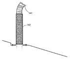
取付部材142が筐体1の面に接合される角度は、垂直方向あるいは略垂直方向であることが好ましい。すなわち、筐体1の面が水平面である場合には、取付部材142と筐体1の面とは直角あるいは略直角であることが好ましい。あるいは、図5に示すように、タッチペン取付部のある筐体1の面がディスプレイ13への操作が容易なように斜めに傾いている場合であっても、取付部材142と筐体1の面との角度は、取付部材142が筐体1の面に接合される角度が垂直方向あるいは略垂直方向であるような角度であることが好ましい。
【0054】
このような構造であるため、ケーブル141の重みが取付部材142とタッチペン14とに分散され、取付部材142がない場合にタッチペン14にかかっていたケーブル141の重みが軽減される。その結果、タッチペン14を用いてお絵描き操作を行なうユーザの手にかかる負担が大幅に軽減される。
【0055】
またこのような構造であるため、ケーブル141の根元が取付部材142の弾性によってディスプレイ13を備える面から持上げられ、ケーブル141の長さのうちの取付部材142の長さや角度に応じた長さ分だけしかディスプレイ13を備える面に載荷されない。その結果、ユーザがタッチペン14を用いてお絵描き操作を行なう際のケーブル141の取り回しがよくなるため、ケーブル141が邪魔にならず、入力操作が行ないやすくなる。
【0056】
また、取付部材142は、その弾性限界となる強度以上の強度がかかると、その強度に応じて強度のかかった方向に撓む。そして、その弾性限界となる強度以上の強度が取除かれると、取付部材142は、その弾性力によって、筐体1の面と所定の角度を保つような元の状態に戻る。すなわち、そのままの状態でタッチできない範囲をタッチするときなどには、ユーザがタッチペン14を引張ることでケーブル141が取付部材142に弾性限界となる強度以上の強度を伝え、取付部材142は引張られた方向に撓んで倒れる。
【0057】
このような構造であるため、タッチペン取付部からタッチペン14の位置までの距離が取付部材142の長さに応じてその方向に延長され、取付部材142が撓まない元の状態ではタッチできない範囲にタッチすることが可能になる。
【0058】
また、図6を用いて、取付部材142の長さL1と、当該タッチペン取付部からディスプレイ13までの距離L2との関係について説明する。
【0059】
上述のように、ケーブル141の長さのうちの取付部材142の長さや角度に応じた長さ分が取付部材142の弾性によってディスプレイ13を備える面から持上げられるため、取付部材142の長さL1は長い方がユーザがタッチペン14を用いてお絵描き操作を行なう際のケーブル141の取り回しが容易になるが、取付部材142は弾性限界となる強度以上の強度で引張られた方向に撓んで倒れるため、取付部材142の材質によっては取付部材142の長さL1が長すぎるとディスプレイ13に取付部材142が接触してディスプレイ13を傷つける可能性もある。そのため、取付部材142の長さL1は、タッチペン取付部からディスプレイ13までの距離L2以下であることが好ましい。すなわち、L1<L2であることが好ましい。このようにすることで、取付部材142が最大限倒れた場合であっても、取付部材142がディスプレイ13に接触することは回避され、倒れた取付部材142がディスプレイ13を傷つけることがない。
【0060】
さらに図6を用いて、取付部材142の構造の特徴について説明する。
上述のように、ユーザがタッチペン14を引張ることでケーブル141が取付部材142にその引張強度を伝えるため、ケーブル141の取付部材142の上端と接する部分には応力が集中する。また、ユーザがタッチペン14を操作することで、付随するケーブル141が取付部材142の上端に擦り付けられることがあり得る。そこで、取付部材142の上端に、保護部材143が備えられることが好ましい。保護部材143は、ケーブル141が押付けられても、あるいはケーブル141が擦り付けられても、ケーブル141を傷つけない柔らかい部材であって、樹脂やラバーなどが好ましい。あるいは、保護部材143に替えて、取付部材142の上端の構造が保護構造となっていてもよい。具体的には、取付部材142の上端が丸みを帯びた形状などであることが好ましい。言うまでもなく、取付部材142の上端の構造はこのような構造に限定されず、ケーブル141を傷つけ難い構造であれば他の構造であってもよい。このような構造にすることで、取付部材142の上端、すなわち、取付部材142の筐体1に接合されている側と反対の端部がケーブル141を傷つけ難くすることができる。
【0061】
なお、本発明において、タッチペン14に付随するケーブル141の接合される筐体1の面、つまりタッチペン取付部の含まれる面は、ディスプレイ13が備えられる面に限定されない。すなわち、変形例として、タッチペン14に付随するケーブル141は、筐体1のお絵描き操作側の面であって、ディスプレイ13が備えられる面以外の面、たとえば図7に示されるように、お絵描き操作側のユーザに相対する面の、ディスプレイ13より高い位置に接合されていてもよい。またたとえば、お絵描き操作側のユーザの左右のパネル、あるいは上部(天井部分)のパネルで構成される面の、ディスプレイ13より高い位置に接合されていてもよい。
【0062】
このように、お絵描き操作を行なうディスプレイ13が備えられる面以外の面にタッチペン14に付随するケーブル141が接合されることでも、ケーブル141の長さのうちの接合位置に応じた長さ分だけしかディスプレイ13を備える面に載荷されないため、ユーザがタッチペン14を用いてお絵描き操作を行なう際のケーブル141の取り回しがよくなる。
【0063】
さらに、変形例において、ケーブル141の素材を伸縮性のある素材(たとえばバネやラバーや樹脂)などにして、タッチペン14を用いるときにユーザが手元に引き寄せることが可能であるようにすることで、取り回しをよりよくすることができる。あるいは、ケーブル141の形状を伸縮性のある形状(バネ形状など)にすることでも同様に取り回しをよりよくすることができる。
【0064】
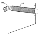
また、図7に丸で示される部分であって、変形例におけるケーブル141の取付け部分であるタッチペン取付部もまた、上述と同様の構造とすることができる。すなわち、図8に示されるように、変形例におけるタッチペン取付部もまた、ケーブル141と筐体1との接合部分に上述の取付部材142を含む構造とすることで、上述と同様の効果を得ることができる。さらに、タッチペン14に付随するケーブル141がお絵描き操作側のユーザに相対する面(図7)や左右のパネルなど側面に備えられる場合には、図9に示されるように、取付部材142が水平よりやや上を向く角度に接合されることでその効果はより大きくなる。
【0065】
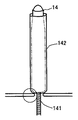
さらに、取付部材142の構造の他の変形例として、図10に示されるように、タッチペン14を格納できる構造とすることができる。すなわち、取付部材142はケーブル141に接合されておらず、タッチペン14を用いていない際には内部にタッチペン14を格納し、ユーザがタッチペン14を用いてお絵描き操作を行なう際にその中から引出すような構造とすることができる。このようにすることで、お絵描き操作に用いていないときのタッチペン14の破損や汚れを効果的に防止することができる。また、お絵描き操作にタッチペン14を用いていないときにディスプレイ13にケーブル141がかかることがなく、操作性が向上する。
【0066】
なお、この場合、タッチペン14に付随するケーブル141は、タッチペン14の格納あるいは引出しに伴なって筐体1に設けられた孔を通るので、筐体1の孔の周囲部分(図10で丸で示される部分)の構造は、ケーブル141を傷つけない構造であることが好ましい。具体的には、ケーブル141を傷つけない柔らかい素材を用いた保護部材を備える、あるいは、図10に示されるように、丸みを帯びた形状とする、などであることが好ましい。
【0067】
さらに、タッチペン14が筐体1の内部に落ち込まないように、筐体1に設けられる孔の直径は、ケーブル141の直径より大きく、タッチペン14のケース1410(図13参照)の直径より小さいことが好ましい。
【0068】
次に、図11のフローチャートを用いて、本実施の形態における写真自動販売機での処理について説明する。図11のフローチャートに示される処理は、PC101のCPUが、記憶装置に記憶されるプログラムをメモリに読出して実行することによって実現される。
【0069】
まず、当該写真自動販売機に備わる電源スイッチ29が投入されると、各種装置の電源が投入される。すると、PC101の記憶装置に格納された動作プログラムが起動する。PC101は動作プログラムを実行することで、始めに各種装置が正常に接続されているかチェックし、初期化が必要な装置に対しては初期化を実行する。その後、当該写真自動販売機の利用を促すタイトルデモをモニタ22に表示し、ディスプレイ13には撮影を先に行なう旨の待機画面を表示する。同時に音声をスピーカ23から出力する(S101)。
【0070】
タイトルデモが表示されている状態で、サービスパネル105において、テストボタンが押下されたことを検出すると(S103でYES)、当該写真自動販売機のメンテナンスを行なうためのテストモードを起動し、種々の設定を受付ける(S105)。
【0071】
テストモードは、写真自動販売機の設置者が写真自動販売機を操作するためのモードであり、このモードにおいては当該写真自動販売機の利用状況(たとえばコイン投入数など)の確認や、カメラ21、プリンタ12など周辺機器の調整ができる。ここで写真自動販売機の設置者とは、当該写真自動販売機を設置し営業を行なっている店舗などの経営者、管理者、および従業員であり、営業中に、利用者に対応できるものである。
【0072】
一方、コイン制御部107において当該写真自動販売機を利用するためのコインがコイン投入口26から投入されたことなど、対価の受付を検出すると(S103でNO、かつS107でYES)、PC101は、以降のプレイを開始する。
【0073】
始めに、PC101のCPUは、コース選択画面をモニタ22に表示し、以降のプレイの方法であるコースの選択を受付ける(S109)。動作プログラムには、各々のコースに対応する処理が用意されており、PC101のCPUは、ステップS109での選択結果に応じた処理に分岐して実行する。
【0074】
次に、PC101のCPUは、ステップS109で選択されたコースに応じた処理を実行し、カメラ21が取得する撮影画像を、モニタ22にリアルタイムに表示する(S111)。ステップS111で撮影画像がモニタ22にリアルタイムに表示されることで、ユーザは、モニタ22に表示される画像を見ながら、好みの表情やポーズをとることができる。なお、ここではカメラ21が取得した画像をそのままモニタ22に表示してもよいし、左右に反転処理して表示してもよい。左右に反転処理して表示した場合、ユーザの姿を鏡に写す方向と同じ方向でモニタ22に表示することができる。そのため、ユーザは、モニタ22を見ながら好みの表情やポーズをとることが容易になる。
【0075】
さらにユーザは、モニタ22に表示される操作画面(図示せず)およびスピーカ23から流れる音声に従って、背景カーテンの選択をしたり、カメラ21を好みの位置に移動させたり、カメラ21を回転、または向きを調整したりすることができる。これらの指示は、操作ボタン51などで受付ける。さらに、カメラ21の近傍などにカメラ21の向きやズーム等の指示を行なうボタンなどが備えられる場合には、それによってカメラ21の向きやズーム等の指示を受付ける。
【0076】
PC101はカメラ21に撮影信号を送信しカメラ21がその撮影信号に応じてシャッタを切ることで、カメラ21からPC101の記憶装置に静止画像が取込まれる。撮影のタイミングは、PC101が動作プログラムにしたがって所定のタイミングで自動的に撮影信号をカメラ21に送信し、時間経過と共に「3、2、1」などのカウントダウンをモニタ22あるいはスピーカ23に出力してユーザに通知してもよい。あるいは、撮影画面を見ながら任意のタイミングでユーザが操作ボタン51を押すことで、PC101が制御部102を介して操作ボタン51からの指示信号を受信し、指示信号を受信したタイミングで撮影信号をカメラ21に送信してもよい。ステップS111では、このような撮影を所定回数繰返し行なう。
【0077】
なお、ステップS111において、フレームや背景の選択も同時に受付けてもよい。あるいは、ステップS111以前に編集用画像である背景画像やフレーム画像(前景画像)の選択を受付けている場合、PC101はモニタ22に撮影画像と共に表示してもよい。これは、CPUが記憶装置から所定の編集用画像を読出し、モニタ22に表示するためのメモリ上の画層であって、撮影画像を表示するための画層とは異なる画層に編集用画像を置くことで実現される。また、PC101において、撮影画像と編集用画像との合成処理を実行して表示してもよい。
【0078】
ステップS111において所定枚数、あるいは所定時間の撮影が終了すると、PC101は、制御部102を介して撮影された複数の撮影画像の中から以降の処理に用いる画像の選択を受付ける(S113)。
【0079】
次に、PC101は、ステップS113で選択された各撮影画像に対して明るさ調整を実行する(S115)。
【0080】
次に、PC101は、ステップS113で選択された撮影画像であって、以降の編集処理を行なった後に印刷するためのシールレイアウトを決定する(S117)。
【0081】
次に、PC101は、ステップS113で選択された各撮影画像に対する編集入力を受付ける(S119)。編集入力を終了すると、PC101は撮影された画像と編集入力された画像とを合成し、ステップS117で選択されたシールレイアウトにしたがって印刷画像データを生成してプリンタ12に出力させる(S121)。なお、その際、ユーザから、シール等の印刷媒体に印刷する画像の選択を受付けてもよい。また、編集入力に失敗した画像などを印刷しないような選択を受付けてもよい。
【0082】
以上の処理が、1組のユーザが本実施の形態の写真自動販売機で行なう一連のプレイである。そして、上述の処理を終了すると、次に対価の受付が検出されるまで、再度タイトルデモをスピーカ23、モニタ22、およびディスプレイ13から出力し、対価の受付が検出されると再び上述の処理を繰返す。
【0083】
なお、上述のプレイ順においてはステップS119の編集入力以前にステップS117のシールレイアウトの選択を行なうものとしているが、プレイ順はこの順に限定されるものではなく、編集入力終了後にシールレイアウトの選択を行なってもよい。
【0084】
上述の一連のプレイのうち、ステップS119での編集入力を含むいくつかの操作、たとえばステップS113での写真選択やステップS115での明るさ調整やステップS117でのシールレイアウト選択などが、お絵描き操作側でタッチペン14とディスプレイ13とからなる入力装置100を用いて行なわれる。上の処理のうち、ステップS119での編集入力について、表示画面の具体例を挙げながら詳細に説明する。
【0085】
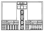
すなわち、ステップS119での編集入力では、PC101は、図12に示されるような編集画面をディスプレイ13に表示し、ユーザから、編集入力に用いる編集の種類(ツール)の選択や、編集用画像の選択や、編集用画像を入力する位置の指定などをタッチペン14で受付ける。
【0086】
図12に示される編集画面においては、ステップS113で選択された撮影画像のうちの2つの撮影画像が編集可能に表示され、その撮影画像と共に、当該編集入力のツールである「ペン」および「スタンプ」で用いられる編集用画像や線種が表示される。また、入力した画像を消すための「ケシゴム」、すでに選択されている背景画像を消すための「背景ケシゴム」、入力操作を1つ前の状態に戻すための「ひとつもどる」、画像入力を最初からやり直すための「はじめから」などのボタンが表示される。なお、編集画面は図12に示される画面に限定されるものではなく、たとえば、さらに編集入力のツールとして「フレーム」や「ライン」などが表示されていてもよい。
【0087】
ユーザは、これらのボタンをタッチペン14でタッチすることで使用するツールを選択する。なお、当該写真自動販売機が複数のタッチペン14を備える場合には、図12に示される編集画面の左右の両方の編集が各々のタッチペン14で同時になされてもよい。
【0088】
PC101は、撮影された画像と、ユーザに選択された編集用の画像とを、メモリ上のそれぞれ別の画層に展開させ、ディスプレイ13上にそれら画層を重ねて表示する。それぞれの画層のどちらを上に表示するかは、用途により設定されている。たとえば、編集入力された画像を撮影された画像の前景画像とする場合には、編集入力された画像が上の画層となる。さらに編集入力された画像は、スタンプ画像の層、フレーム画像の層など、それぞれ複数の画層で構成されていてもよい。
【0089】
編集を行なうための編集入力時間は、予め設定されている。そして、ディスプレイ13上に残り時間を表示し、カウントダウンを行なう。残り時間が0になると編集入力が終了する。または、画面に用意された「おしまい」ボタンにタッチすることで強制的に終了させることもできる。
【0090】
ステップS119などにおいて、タッチペン14とディスプレイ13とを含む入力装置100で情報を入力する際には、タッチペン14でタッチされた位置を示す座標の情報がディスプレイ13側で検出され、ディスプレイ13側で指示信号に変換されてPC101に入力される。
【0091】
次に、電磁誘導方式あるいは静電結合方式を採用した入力装置100を構成するタッチペン14の構成の具体例を図13に示す。
【0092】
図13を参照して、タッチペン14は、全体が筒状のケース1410に格納されており、その先端(ディスプレイ13にタッチする側)に、ディスプレイ13にタッチして位置を指示するペンスイッチである検出軸1420を備える。検出軸1420は、バネ1440あるいはゴムなどの弾性のある素材で、フォトインタラプタ1480に接続される。
【0093】
検出軸1420は伸縮方向(タッチペン14の長手方向)に可動であって、ディスプレイ13などで押される(ディスプレイ13などにタッチする)ことで検出軸1420が縮む方向に動いてケース1410内に所定長さ押込まれる。また、検出軸1420がディスプレイ13などから離れることで、バネ1440の反発力により元の位置に戻る。
【0094】
光遮蔽センサであるフォトインタラプタ1480は、LEDなどの投光部1450とフォトトランジスタなどの受光部1460とを一体的に備えた光透過型のフォトカプラの一種である。検出軸1420の逆側(ケース1410の内部側)には遮蔽部1430が備えられ、検出軸1420の伸縮に連動して投光部1450と受光部1460とで構成される空間をタッチペン14の長手方向に移動して投光部1450から投光された光の一部あるいはすべてを遮蔽する。フォトインタラプタ1480は、投光部1450から受光部1460に投光された光の、遮蔽部1430での遮蔽度合いに応じた電位の変化を検出する。
【0095】
基盤1470は、フォトインタラプタ1480でのペンスイッチのON/OFFの検出を制御する。すなわち、フォトインタラプタ1480は、基盤1470から制御信号を受信して、検出した電位がしきい値以下である場合にはペンスイッチONと認識し、しきい値以上である場合にはペンスイッチOFFと認識する。そして、フォトインタラプタ1480は、認識したペンスイッチのON/OFFを示す信号を基盤1470に入力する。
【0096】
基盤1470は、フォトインタラプタ1480から入力された信号に基づいて、ペンスイッチのON/OFFを示すペンスイッチ信号を、ケーブル141を介して入力装置100の図示しない出力部に対して出力する。そして、入力装置100の出力部は、入力装置100において検出された情報を示す検出信号をPC101に出力する。
【0097】
さらに、上述の検出軸1420は、入力装置100が採用している方式(電磁誘導方式あるいは静電結合方式)に応じた機能を備えるものとする。これらの方式を用いた入力装置は広く一般的に用いられており、検出軸1420が備える機能は公知の技術を用いたものであるため、ここでの詳細な説明は行なわない。
【0098】
ディスプレイ13側は、検出軸1420の備える機能によってタッチペン14の検出軸1420の位置に応じたディスプレイ13上の座標を検出する。具体的には、入力装置100が電磁誘導方式を採用したものである場合、ディスプレイ13側は検出軸1420が備える磁界発生機能によって発生した磁界を検出することでタッチペン14の検出軸1420の位置に応じたディスプレイ13上の座標を検出する。これは、入力装置100がディスプレイ13の面に沿って図示しない磁界検出装置などの座標検出装置を備えることで実現される。入力装置100が静電結合方式を採用したものであっても同様である。
【0099】
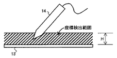
ディスプレイ13側に備えられる磁界検出装置などの座標検出装置は、ディスプレイ13から所定範囲にあるときのディスプレイ13に投影した検出軸1420の座標を検出できる。すなわち、ディスプレイ13側に備えられる座標検出装置は、図14に示すように、ディスプレイ13から距離Hにある所定範囲(座標検出範囲)に検出軸1420が存在するときに、その座標を検出することができる。
【0100】
ディスプレイ13側に備えられる座標検出装置は、入力装置100の図示しない出力部に、タッチペン14の座標が検出された場合には検出された座標を示し、タッチペン14の座標が検出されない場合にはその旨(座標不特定)を示す座標信号を出力する。そして、入力装置100は、タッチペン14から入力されたペンスイッチのON/OFFを示すペンスイッチ信号と共に、ディスプレイ13側に備えられる座標検出装置から入力された座標信号をPC101に対して出力する。
【0101】
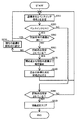
入力装置100でのPC101への検出信号の出力処理について図15のフローチャートに示す。すなわち、図15を参照して、タッチペン14の検出軸1420が図14に示される座標検出範囲内に存在してディスプレイ13側に備えられる座標検出装置においてタッチペン14の座標が検出された場合には(S200でYES)、座標検出装置は座標信号に検出した座標情報を保持して、入力装置100の図示しない出力部に座標信号を出力する(S205)。また、タッチペン14の検出軸1420が図14に示される座標検出範囲内に存在せずディスプレイ13側に備えられる座標検出装置においてタッチペン14の座標が検出されない場合には(S200でNO)、座標検出装置は座標信号に座標が検出されない旨を示す座標不特定情報を保持して、入力装置100の図示しない出力部に座標信号を出力する(S210)。
【0102】
また、そのときに、タッチペン14の基盤1470がフォトインタラプタ1480から入力された信号に基づいてペンスイッチのONを検出すると(S215でYES)、ペンスイッチONを示すペンスイッチ信号を入力装置100の図示しない出力部に座標信号を出力する。そして、入力装置100の出力部は、座標検出装置から入力された座標信号とペンスイッチONを示すペンスイッチ信号とを含む検出信号をPC101に対して出力する(S220)。また、タッチペン14の基盤1470がフォトインタラプタ1480から入力された信号に基づいてペンスイッチのOFFを検出すると(S215でNO)、ペンスイッチOFFを示すペンスイッチ信号を入力装置100の図示しない出力部に座標信号を出力する。そして、入力装置100の出力部は、座標検出装置から入力された座標信号とペンスイッチOFFを示すペンスイッチ信号とを含む検出信号をPC101に対して出力する(S225)。
【0103】
なお、上述の座標の検出(S200〜S210)と、ペンスイッチON/OFFの検出(S215)との順は、上に示される順に限定されず、先にペンスイッチON/OFFの検出が行なわれてもよい。また、上述の出力処理は、予め設定されているタイミング(所定間隔等)で実行されてもよいし、PC101から実行を指示する指示信号が入力されたタイミングで実行されてもよい。
【0104】
PC101は、入力装置100から検出信号を受付けると、その信号に基づいて各種処理を実行する。その1つの具体例として、上述の図12に示される編集画面において当該編集入力のツールである「ペン」が選択され、PC101において撮影画像に対して編集用の画像である線画を入力する場合の処理について、図16のフローチャートを用いて説明する。先述のように、編集入力処理においては、編集用の画像である線画は撮影画像とは異なる編集用の画層に展開される。したがって、以下の処理は、編集用の画層上で展開される処理である。
【0105】
図16を参照して、始めに、PC101は、所定間隔で、入力装置100から座標信号とペンスイッチ信号とを含む検出信号を受信する(S250)。そして、CPUにおいて解析した結果、ペンスイッチ信号がペンスイッチONを示す信号である場合(S255でYES)、さらに、ステップS250で受信した座標信号に含まれる座標(以下、現在の座標と言う)が、この処理の1つ前に実行した処理の際に取得した座標(以下、前回の座標と言う)と同じであるか否か判定する(S260)。判定の結果、現在の座標が前回の座標と異なっている場合(S260でNO)、さらに、開始点が設定されているか否かを判定する(S265)。開始点とは、描画する線画の一方の端点であって、線画の描画を開始する点を指す。
【0106】
ステップS265での判定の結果、開始点が設定されていない場合には(S265でNO)、現在の座標を開始点に設定し(S270)、処理を始めに戻して次の検出信号の受信を待つ。ここでの処理は、新たに現在の座標から次の線画を描画する線画を描き始める場合の処理が該当する。
【0107】
また、ステップS260での判定の結果、現在の座標が前回の座標と同じである場合にも(S260でYES)、処理を始めに戻して次の検出信号の受信を待つ。ここでの処理は、タッチペン14を用いて操作しているユーザが、前回タッチした位置からタッチペン14を移動させていない場合の処理が該当する。
【0108】
一方、ステップS265での判定の結果、開始点が設定されている場合には(S265でYES)、その開始点から現在の座標まで、線画を描画する(S275)。そして、線画の終点である現在の座標を、次の開始点として設定し(S280)、処理を始めに戻して次の検出信号の受信を待つ。この、ステップS250〜S280の処理を繰返すことで、連続的に線を引いていくことができる。
【0109】
また、ステップS250で受信したペンスイッチ信号がペンスイッチOFFを示す信号である場合(S255でNO)、開始点が設定されていないときには(S285でNO)、処理を始めに戻して次の検出信号の受信を待つ。ここでの処理は、タッチペン14を用いて操作しているユーザが、たとえばタッチペン14をディスプレイ13から上げたままにしているなど、操作を中断している場合の処理などが該当する。
【0110】
一方、ステップS250で受信したペンスイッチ信号がペンスイッチOFFを示す信号である場合であって(S255でNO)、開始点が設定されているときには(S285でYES)、次回の処理のために現在設定されている開始点をクリアして(S290)、線画の入力処理を終了する。ここでの処理は、タッチペン14を用いて操作しているユーザが、タッチペン14をディスプレイ13から離してその線画の描画を終了した場合の処理が該当する。
【0111】
なお、上述のステップS250での検出信号の受信は、上述の処理とは別に上述の処理と並行して動作する並列処理(たとえばスレッド処理)の中で行なわれてもよい。この場合、前記並列処理内では、一定の間隔(たとえば約6ms間隔)で検出信号を受信し、受信した信号をPC101内のメモリに保持する。そして、上述のステップS250の処理を、メモリに保持された信号を参照する処理に置換えて、以降の処理を行なう。
【0112】
ところで、本発明にかかる画像入力装置で用いる入力装置100は、上述のように、タッチペン14の座標が検出できない場合でも、ペンスイッチ信号を出力することを特徴とする。そこで、入力装置100からペンスイッチ信号と座標信号とを含む検出信号を受信したPC101では、図17のフローチャートに示す判定処理を実行して、タッチペン14の状態を判定することを特徴とする。なお、図17に示される判定処理は、写真自動販売機でプレイ中に、プレイと並行して実行されてもよいし、プレイを進行させる処理中の必要に応じて随所で実行されてもよい。
【0113】
図17を参照して、PC101は、入力装置100から受信した検出信号を解析し、ペンスイッチ信号がペンスイッチONを示す信号であるか否かを判定する(S300)。ペンスイッチ信号がペンスイッチONを示す信号であって(S300でYES)、かつ、座標信号が有効なものである場合(S305でYES)、処理を始めに戻して次の検出信号の監視を続ける。この場合は、正常にタッチペン14でディスプレイ13を操作しているものと想定される。
【0114】
一方、ペンスイッチ信号がペンスイッチONを示す信号であって(S300でYES)、かつ、座標信号が座標不特定情報を示す信号である場合(S305でNO)、タッチペン14の状態がONのままの状態であると判定する(S310)。これは、タッチペン14が図14に示される座標検出範囲にない(座標信号が座標不特定情報を示す信号である)にも関わらずペンスイッチがONであるような状態であって、タッチペン14の検出軸1420がディスプレイ13にタッチしていないのにペンスイッチがONと検出されるという不具合がタッチペン14に発生していることを示している。
【0115】
さらに、PC101は、上述の判定処理の結果を、たとえばディスプレイ13に図18に示されるような通知画面を表示して、利用者や設置者に通知することが好ましい。あるいは、完全な不具合でない場合もあり得るので、図19に示されるような通知画面を表示して、一旦不具合であるか否かを確認させるような通知を行なうことも好ましい。その場合、図19に示される通知したがってタッチペン14でディスプレイ13をタッチしてタッチペン14が正常に復帰したときには、当該通知画面を表示する直前のプレイ中の画面に処理を戻し、プレイを続行することがより好ましい。なお、このように確認を行なう場合には、タッチペン14で1回タッチして判定を行なってもよいし、複数回タッチして判定を行なってもよい。
【0116】
また、このような通知は、上述の判定処理を複数回行なって、その判定結果が規定回数不具合であるという判定結果であった場合、あるいは規定時間内に規定回数不具合であるという判定結果であった場合に行なうことも好ましい。タッチペン14に不具合が発生しているという判定結果は、実際にはタッチペン14に不具合が発生しておらず、たとえばノイズなどの影響を受けて誤検出されるような場合もあり得るからである。
【0117】
さらに、このような通知を行なう際には、写真自動販売機での操作を待機した状態とすることが好ましい。また、プレイの制限時間(たとえば、前述の編集入力時間など)のカウントを中断することがより好ましい。ユーザによっては、プレイ中にこのような通知が行なわれることで、プレイが止まってしまい、不満を感じる場合もあるからである。
【0118】
またさらに、当該通知をプレイ中に行なうのではなく、プレイ終了後の、ユーザの利用を待機している状態(ステップS101のタイトルデモ表示中)に行なうことがより好ましい。これは、プレイ中に不具合の判定が行なわれた場合に、通知画面を一旦PC101のメモリに格納し、プレイ終了後にメモリから通知画面を読出して表示することで実現される。
【0119】
また、判定されたタッチペン14の状態(判定日時、判定回数、不具合発生の有無など)をPC101の記憶装置に記憶し、ステップS105のテストモード起動中にタッチペン14の状態の履歴を表示するようにしてもよい。そのようにすることで、設置者は、タッチペン14の状態をさらに詳細に知ることができる。たとえば、不具合の発生する回数が日を追うごとに増してくるような場合、そろそろタッチペン14が消耗して交換時期であることを予想でき、予めタッチペン14の替えを準備しておくことができて便利である。
【0120】
なお、判定結果の通知方法は、図18や図19に示されるような通知画面の表示に限定されるものではない。ディスプレイは外部から見えにくい構造であるため、利用者がいない待機中に案内が表示されても異常に気づきにくく、装置の稼動が停止した状態で放置され稼動率が低下することになる。そこで、ディスプレイの表示と同時にスピーカ23から通知音を出力して、判定処理の結果の案内を通知するようにすれば、異常を発見しやすくなる。また、当該写真自動販売機の上部など、写真自動販売機の外部であって、写真自動販売機外から見える位置に図示されない通知装置(LED、ランプ、ディスプレイなどの照明装置等)を備え、それらを用いて判定結果を通知してもよい。さらに、他の出力手段を備える場合には、他の出力を行なって通知してもよい。
【0121】
より具体的には、判定処理の結果、タッチペン14に不具合が発生している場合に、スピーカ23から短いビープ音を出力する、ディスプレイ13上であって操作に影響ない範囲に不具合の発生を知らせるマークなどを表示する、LEDなどの照明装置を発光させる、などの通知を行なってもよい。
【0122】
PC101においてこのような処理が実行されることによって入力装置100における不具合の発生が自動的に検出され通知されるので、当該写真自動販売機の設置者は、タッチペン14に不具合が発生していることを素早く把握することができ、当該不具合に対して的確に対処することができる。そのため、不具合のあるタッチペンのまま稼動し続けることが減り、利用者に操作性の悪い装置という印象を抱かせることなく、操作性の高い状態を維持することができる。
【0123】
なお、変形例として、PC101は上述の図17に示される判定処理に替えて、タッチペン14の状態を通知する処理を行なってもよい。すなわち、変形例におけるPC101は、入力装置100から検出信号を受信すると、検出信号に含まれるペンスイッチ信号を解析して、ペンスイッチのON/OFFを通知する処理を行なう。
【0124】
変形例における通知方法も、上述の判定結果の通知方法と同様に、ディスプレイ13にタッチペン14の状態を通知する通知画面を表示する方法が挙げられる。また、その他の方法として、たとえば、ペンスイッチがONまたはOFFになったときに、スピーカ23から短いビープ音を出力する、ディスプレイ13上であって操作に影響ない範囲にペンスイッチのON/OFFが認識できる表示をする、LEDなどの当該写真自動販売機外部に設置された照明装置である通知装置をペンスイッチがONの時点灯しペンスイッチがOFFの時消灯するように制御する、などの方法が挙げられる。
【0125】
変形例においてPC101でこのような通知処理が実行されることで、店舗巡回中に設置者はタッチペン14の状態や使用状態を監視できる。すなわち、タッチペン14の故障を早期に発見できるだけでなく、ディスプレイ13以外の部分をタッチペン14でつつく、タッチペン14のスイッチ部を指で触るなど、入力操作以外の目的でタッチペン14を使用するなどの悪戯も早期に発見することができ、適切に対応することでタッチペン14の劣化を防止することができる。
【0126】
また、当該装置がタッチペン14からの入力を求めない場面、たとえばプレイ中の待機を要する場面(画像準備中など)において、規定回数以上(たとえば、10回以上)タッチペン14のペンスイッチがONになったときに、スピーカ23bより「ペンで遊ばないで下さい」などの注意を促がす案内を流してもよい。
【0127】
さらに他の変形例として、PC101が入力装置100から受信した検出信号に基づいて他の判定処理を実行してもよい。他の変形例において、PC101は、入力装置100から随時送出される検出信号のうち、ペンスイッチ信号をタイマ25を用いて監視して、タッチペン14の状態を判定する。図20のフローチャートを用いて、他の変形例における判定処理について説明する。
【0128】
図20を参照して、PC101は、入力装置100から受信した検出信号を解析し、ペンスイッチ信号がペンスイッチONを示す信号であるか否かを判定する(S400)。ペンスイッチ信号がペンスイッチOFFを示す信号である場合には(S400でNO)、タイマ25を用いてペンスイッチのOFFを監視し、ONになった状態からOFFになるまでの時間を計時しているオフ監視タイマをクリアする(S405)。また、ペンスイッチ信号がペンスイッチONを示す信号である場合には(S400でYES)、タイマ25を用いてペンスイッチのONを監視し、OFFになった状態からONになるまでの時間を計時しているオン監視タイマをクリアする(S410)。
【0129】
次に、ペンスイッチOFFである場合(S400でNO)、そのときにすでにオン監視タイマがセットされているか否かをチェックし(S415)、オン監視タイマがセットされていない場合には(S415でNO)、規定の監視時間(たとえば30秒など)をオン監視タイマにセットする(S420)。この処理は、ペンスイッチがONからOFFに切替わった1回目に行なわれる処理である。そして、処理をステップS400に戻し、次に受信した検出信号についての判定を繰返す。
【0130】
一方、ペンスイッチOFFであって(S400でNO)オン監視タイマがセットされている場合には(S415でYES)、セットされているオン監視タイマを1デクリメントする(S425)。ペンスイッチOFFが継続する間は、オン監視タイマが0になるまで上述のステップS405,S415,S425の処理を繰返す(S430でNO)。そして、オン監視タイマが0になると(S430でYES)、つまり、ペンスイッチがOFFのままで規定時間を経過した場合、PC101は、ペンスイッチがONにならない状態(不具合が発生している)と判定する(S435)。
【0131】
ペンスイッチがONである場合(S400でYES)も同様にして、そのときにすでにオフ監視タイマがセットされているか否かをチェックし(S440)、オフ監視タイマがセットされていない場合には(S440でNO)、規定の監視時間(たとえば30秒など)をオフ監視タイマにセットする(S445)。この処理は、ペンスイッチがOFFからONに切替わった1回目に行なわれる処理である。そして、処理をステップS400に戻し、次に受信した検出信号についての判定を繰返す。
【0132】
一方、ペンスイッチONであって(S400でYES)オフ監視タイマがセットされている場合には(S440でYES)、セットされているオフ監視タイマを1デクリメントする(S450)。ペンスイッチONが継続する間は、オフ監視タイマが0になるまで上述のステップS410,S440,S450の処理を繰返す(S455でNO)。そして、オフ監視タイマが0になると(S455でYES)、つまり、ペンスイッチがONのままで規定時間を経過した場合、PC101は、ペンスイッチがOFFにならない状態(不具合が発生している)と判定する(S460)。
【0133】
上述の処理は、写真自動販売機などの本発明の画像入力装置の利用においては、タッチペン14で操作する回数が多く、予め設定した規定時間内に、1回もペンスイッチがONまたはOFFにならないことはあり得ないことを想定して行なう判定処理である。つまり、予め設定した規定時間内に1度もペンスイッチがONにならなかったならばペンスイッチがONにならない故障が発生していると判定し、1度でもOFFになれば故障ではないと判定する。また逆に、予め設定した規定時間内に1度もペンスイッチがOFFにならなかったならばペンスイッチがOFFにならない故障が発生していると判定し、1度でもONになれば故障ではないと判定する。
【0134】
なお、上述の判定処理においては、タイマ25での計時方法が減算カウンタを用いる場合を説明しているが、本発明においてタイマ25における計時方法は限定されず、同様に時間経過を監視できるものであれは、加算タイマなど他の計時方法であってもよい。また、上述の判定処理においては、PC101がタッチペン14の状態としてペンスイッチがONにならない状態とOFFにならない状態との両方を判定するものとしているが、いずれか一方の状態のみを判定してもよい。また、タイマを用いた上述の判定方法を、一定時間入力を要しない場面(画像準備中など)においては行なわないようにすることが好ましい。この判定方法は、タッチペンを用いた入力操作が最も頻繁に行なわれる編集中(図11のステップS119)において用いられることが最も好適である。
【0135】
さらに、このような入力装置100を含む画像入力装置において行なわれる画像入力方法を、プログラムとして提供することもできる。このようなプログラムは、コンピュータに付属するフレキシブルディスク、CD−ROM(Compact Disc−Read Only Memory)、ROM(Read Only Memory)、RAM(Random Access Memory)およびメモリカードなどのコンピュータ読取り可能な記録媒体にて記録させて、プログラム製品として提供することもできる。あるいは、コンピュータに内蔵するハードディスクなどの記録媒体にて記録させて、プログラムを提供することもできる。また、ネットワークを介したダウンロードによって、プログラムを提供することもできる。
【0136】
提供されるプログラム製品は、ハードディスクなどのプログラム格納部にインストールされて実行される。なお、プログラム製品は、プログラム自体と、プログラムが記録された記録媒体とを含む。
【0137】
今回開示された実施の形態はすべての点で例示であって制限的なものではないと考えられるべきである。本発明の範囲は上記した説明ではなくて特許請求の範囲によって示され、特許請求の範囲と均等の意味および範囲内でのすべての変更が含まれることが意図される。
【図面の簡単な説明】
【図1】写真自動販売機を筐体1の正面(撮影操作を行なう面)から見たときの外観の具体例を示す図である。
【図2】写真自動販売機を筐体1の背面(お絵描き操作を行なう面)から見たときの外観の具体例を示す図である。
【図3】写真自動販売機の機能ブロック図である。
【図4】タッチペン取付部の具体例を示す図である。
【図5】タッチペン取付部の具体例を示す図である。
【図6】取付部材142の長さL1と、タッチペン取付部からディスプレイ13までの距離L2との関係を説明するための図である。
【図7】タッチペン取付部が、ディスプレイ13が備えられる面以外の面に含まれる場合の具体例を示す図である。
【図8】変形例でのタッチペン取付部の具体例を示す図である。
【図9】変形例でのタッチペン取付部の他の具体例を示す図である。
【図10】他の変形例でのタッチペン取付部の具体例を示す図である。
【図11】写真自動販売機での処理を示すフローチャートである。
【図12】編集画面の具体例を示す図である。
【図13】タッチペン14の構成の具体例を示す図である。
【図14】座標検出範囲の具体例を示す図である。
【図15】入力装置100でのPC101への検出信号の出力処理を示すフローチャートである。
【図16】PC101において撮影画像に対して線画を入力する場合の処理を示すフローチャートである。
【図17】PC101でタッチペン14の状態を判定する判定処理を示すフローチャートである。
【図18】通知画面の具体例を示す図である。
【図19】通知画面の他の具体例を示す図である。
【図20】他の変形例におけるPC101でタッチペン14の状態を判定する判定処理を示すフローチャートである。
【図21】従来のタッチペン取付部の具体例を示す図である。
【符号の説明】
1 筐体、4 撮影ブース、9 プリント取出口、10 印刷中LED、11印刷エラーLED、12 プリンタ、13 ディスプレイ、14 タッチペン、18a,18b,18c 照明ボックス、21 カメラ、22 モニタ、23,23a,23b スピーカ、25 タイマ、26 コイン投入口、28 フロントドア、29 電源スイッチ、30 照明装置、51 操作ボタン、100 入力装置、101 PC、102 制御部、103 電源制御部、104 UPS、105 サービスパネル、107 コイン制御部、141 ケーブル、142 取付部材、143 保護部材、1410 ケース、1420 検出軸、1430 遮蔽部、1440 バネ、1450 投光部、1460 受光部、1470 基盤、1480 フォトインタラプタ。[0001]
TECHNICAL FIELD OF THE INVENTION
The present invention relates to an image input device and an image input method, and more particularly to an image input device and an image input method capable of performing an input operation with good operability.
[0002]
[Prior art]
A touch pen is widely known as an input device for inputting information by touching a display. An input device including such a touch pen is, for example, disclosed in
[0003]
The touch pen is paired with a display to constitute an input device, and is connected to a device of the main body by a cable. As shown in FIG. 21, the base of the cable is fixedly attached to a main body device such as an image input device so as not to be pulled out by a user's touch pen operation.
[0004]
[Patent Document 1]
JP-A-2002-10249
[0005]
[Problems to be solved by the invention]
However, as is conventionally done, simply attaching the base of the cable connected to the touch pen to the main body device causes the weight of the cable to be applied to the touch pen when performing an input operation with the touch pen in hand. The user's hands are burdened, and the input operation becomes tired and unpleasant. This problem occurs particularly when the cable is attached at a position higher than the position of the hand of a user who performs an input operation while holding the touch pen, and this problem also occurs in a general image input device. are doing.
[0006]
In addition, when performing an input operation using the touch pen, there is a problem in that the cable connecting the touch pen and the main unit may hinder the input operation in some cases.
[0007]
The present invention has been made in view of such a problem, and an object of the present invention is to provide an image input device and an image input method capable of performing an input operation with good operability.
[0008]
[Means for Solving the Problems]
In order to achieve the above object, according to an aspect of the present invention, an image input device is an image input device including an input device including a touch pen for touching a display and inputting information, the image input device being associated with the touch pen. The touch pen mounting portion, which is a portion that joins the cable to a predetermined surface of the image input device, has a structure that supports the cable such that the cable and the above-described predetermined surface have a predetermined angle.
[0009]
Further, it is preferable that the structure of the touch pen mounting portion is a structure in which when a strength equal to or more than a predetermined strength is applied, the cable is supported by an elastic member which bends in a direction in which the strength is applied.
[0010]
Further, it is desirable that the structure of the touch pen mounting portion be a structure in which the cable is supported by a member having a length equal to or less than the distance between the touch pen mounting portion and the display.
[0011]
Furthermore, it is desirable that the end of the above-mentioned member opposite to the side joined to the predetermined surface of the image input device has a structure that does not easily damage the cable.
[0012]
Further, the predetermined surface including the touch pen mounting portion is a surface including the display, and the predetermined surface is desirably at a predetermined angle from a horizontal plane.
[0013]
Further, it is desirable that the touch pen mounting portion is located at a position above the horizontal center line of the display.
[0014]
Alternatively, it is desirable that the predetermined surface including the touch pen mounting portion is different from the surface including the display.
[0015]
According to another aspect of the present invention, an image input device is an image input device including an input device including a touch pen for touching a display and inputting information, wherein a cable attached to the touch pen is provided on a surface including the display. It is characterized in that it is joined to a different surface.
[0016]
According to still another aspect of the present invention, an image input method is a method for inputting an image in the above-mentioned image input device, wherein the first image obtaining step of obtaining a first image and the input including the above-mentioned touch pen are provided. A second image specifying step of specifying a second image using the device, an instruction input step of inputting an instruction regarding processing on the first image and the second image using the input device, and And an image processing step of performing image processing on the first image and the second image.
[0017]
BEST MODE FOR CARRYING OUT THE INVENTION
Hereinafter, embodiments of the present invention will be described with reference to the drawings. In the following description, the same parts and components are denoted by the same reference numerals. Their names and functions are the same. Therefore, detailed description thereof will not be repeated.
[0018]
In the present embodiment, the description will be made assuming that the image input device according to the present invention is a photo vending machine. However, the image input device is not limited to the photo vending machine. Other devices that perform processing such as image processing and print processing on an input image in response to an instruction from the device may be used.
[0019]
FIG. 1 is a diagram illustrating a specific example of the appearance of a photo vending machine according to the present embodiment. Photo vending machines are roughly divided into a side that performs a shooting operation and a side that performs a drawing operation that is an input of an image or text, which is called a so-called drawing on an image after shooting. FIG. 1 is a diagram showing a specific example of the appearance when a photo vending machine is viewed from the side of performing a shooting operation.
[0020]
The photo vending machine according to the present embodiment includes a
[0021]
In such a vending machine, a user who is a subject enters a photographing booth 4 which is a photographing space constituted by a
[0022]
Referring to FIG. 1, a monitor for displaying a
[0023]
In addition, around the
[0024]
The
[0025]
The image captured by the
[0026]
As the
[0027]
Furthermore, a fan is inserted into the upper surface of the
[0028]
When a panel (not shown) constituting the photographing booth 4 is made of wood, the panel is largely divided into a left side surface, a right side surface, a back surface, a ceiling surface, and the like. Furthermore, since the rear panel is large, it may be divided into two panels vertically or horizontally. The inner surface of the panel inside the photographing booth 4 is white for the purpose of obtaining indirect light due to the reflection of illumination, black for absorbing the light, and black for the purpose of performing chroma key synthesis. Colors such as blue are given. That is, the color of the inner surface of the panel is appropriately selected at the time of design and development depending on what kind of photographing is performed in the photo vending machine. Further, the panel can be replaced with cloth, vinyl material, or the like. In this case, the panel is fixed to the frame material without slack.
[0029]
A background curtain (not shown) is provided in the photographing booth 4 and used as a background at the time of photographing. A plurality of curtains of various colors and patterns are prepared because the manner in which the subject is captured, particularly the color tone, changes depending on the background color. Also, the background curtain need not be provided. Further, the background curtain may be set by a user's manual operation such as a winding type or a drawer type, or may be automatically set by operating the
[0030]
The side of the photo vending machine is opened so that the user can enter and exit the shooting booth 4, but in order to take into account the user's feelings such as not wanting other people to see the shooting scene. A side curtain (not shown) is provided on the side surface for the purpose of blocking external light. When the entrance to the photography booth is on only one side, a side curtain is provided only on that side. In addition, when it is possible to enter and exit from both sides, side curtains may be provided on both sides. The user opens the side curtain to enter the shooting booth 4 when taking a picture, and closes the side curtain when taking a picture. The color of the back surface of the side curtain (the inside of the photographing booth 4) and the like are appropriately selected for the same reason as the background curtain and the inner surface of the panel.
[0031]
Next, FIG. 2 shows a specific example of the appearance when the photo vending machine is viewed from the back of the housing 1 (the surface on which the drawing operation is performed).
[0032]
Referring to FIG. 2, on the back of
[0033]
The
[0034]
The
[0035]
Further, referring to FIG. 2, a box-shaped print outlet 9 is provided on the side surface of the
[0036]
The shape of the print outlet 9 is not limited as long as the photograph dropped there has such an effect that the photograph does not fall to the ground until the user picks it up. For example, it may be formed of a box-shaped space depressed in the interior direction of the
[0037]
The
[0038]
Next, FIG. 3 shows a functional block diagram of the photo vending machine in the present embodiment, and the functions of the photo vending machine will be described.
[0039]
Referring to FIG. 3, the photo vending machine receives an instruction from
[0040]
The
[0041]
The photo vending machine also includes a power
[0042]
The control unit 102 receives a control signal from the
[0043]
The control unit 102 receives signals from the
[0044]
The
[0045]
The
[0046]
The
[0047]
Further, the
[0048]
Needless to say, the form of the photo vending machine is not limited to the specific examples shown in FIGS. That is, other functions not shown in FIGS. 1 to 3 may be provided, or all of the functions shown in FIGS. 1 to 3 may not necessarily be provided. For example, the
[0049]
As described above, the
[0050]
Further, FIG. 4 shows a specific example of a touch pen mounting portion which is a portion indicated by a circle in FIG. 2 and which is joined to the
[0051]
The
[0052]
The mounting
[0053]
The angle at which the
[0054]
With such a structure, the weight of the
[0055]
Further, with such a structure, the base of the
[0056]
Further, when a strength equal to or more than the strength at which the elastic member is limited is applied, the mounting
[0057]
Due to such a structure, the distance from the touch pen mounting portion to the position of the
[0058]
The relationship between the length L1 of the mounting
[0059]
As described above, the length corresponding to the length and angle of the mounting
[0060]
Further, the features of the structure of the mounting
As described above, since the
[0061]
In the present invention, the surface of the
[0062]
In this manner, even when the
[0063]
Further, in a modified example, the material of the
[0064]
Further, the touch pen mounting portion, which is a portion indicated by a circle in FIG. 7 and is a mounting portion of the
[0065]
Further, as another modified example of the structure of the mounting
[0066]
In this case, since the
[0067]
Furthermore, the diameter of the hole provided in the
[0068]
Next, the processing in the photo vending machine according to the present embodiment will be described with reference to the flowchart in FIG. The processing shown in the flowchart of FIG. 11 is realized by the CPU of the
[0069]
First, when the
[0070]
When the
[0071]
The test mode is a mode in which the installer of the photo vending machine operates the photo vending machine. In this mode, the usage status of the photo vending machine (for example, the number of coins inserted) and the
[0072]
On the other hand, when the
[0073]
First, the CPU of the
[0074]
Next, the CPU of the
[0075]
Further, the user selects a background curtain, moves the
[0076]
The
[0077]
In step S111, selection of a frame or a background may be received at the same time. Alternatively, if the selection of a background image or a frame image (foreground image), which is an editing image, has been received before step S111, the
[0078]
When the predetermined number of images or the predetermined time has been captured in step S111, the
[0079]
Next, the
[0080]
Next, the
[0081]
Next, the
[0082]
The above process is a series of plays performed by one set of users at the photo vending machine of the present embodiment. Then, when the above processing is completed, the title demo is output again from the
[0083]
In the above-mentioned play order, the selection of the seal layout in step S117 is performed before the edit input in step S119. However, the play order is not limited to this order. You may do it.
[0084]
In the series of plays described above, some operations including editing input in step S119, such as selecting a photo in step S113, adjusting brightness in step S115, and selecting a seal layout in step S117, are drawing operations. This is performed using the
[0085]
That is, in the editing input in step S119, the
[0086]
In the editing screen shown in FIG. 12, two captured images of the captured images selected in step S113 are displayed in an editable manner, and together with the captured images, "pen" and "stamp" as editing input tools are provided. Are displayed for editing. Also, "poppy rubber" to delete the input image, "background poppy rubber" to delete the already selected background image, "return one" to return the input operation to the previous state, A button such as "From the beginning" to start over is displayed. Note that the editing screen is not limited to the screen shown in FIG. 12, and for example, a "frame", a "line", or the like may be further displayed as an editing input tool.
[0087]
The user selects a tool to be used by touching these buttons with the
[0088]
The
[0089]
The editing input time for performing the editing is set in advance. Then, the remaining time is displayed on the
[0090]
In step S119 and the like, when information is input with the
[0091]
Next, a specific example of the configuration of the
[0092]
Referring to FIG. 13,
[0093]
The
[0094]
A photo-
[0095]
The
[0096]
The
[0097]
Further, the above-described
[0098]
The
[0099]
A coordinate detection device such as a magnetic field detection device provided on the
[0100]
The coordinate detecting device provided on the
[0101]
The process of outputting the detection signal to the
[0102]
Also, at this time, when the
[0103]
The order of the above-described coordinate detection (S200 to S210) and pen switch ON / OFF detection (S215) is not limited to the order shown above, and the pen switch ON / OFF detection is performed first. You may. The above-described output processing may be executed at a preset timing (a predetermined interval or the like), or may be executed at a timing when an instruction signal for instructing execution is input from the
[0104]
When receiving the detection signal from the
[0105]
Referring to FIG. 16, first,
[0106]
If the result of determination in step S265 is that the start point has not been set (NO in S265), the current coordinates are set as the start point (S270), and the process returns to the beginning to receive the next detection signal. wait. The processing here corresponds to the processing when the user starts to draw a new line drawing from the current coordinates.
[0107]
Also, if the result of determination in step S260 is that the current coordinates are the same as the previous coordinates (YES in S260), the process returns to the beginning and waits for reception of the next detection signal. The processing here corresponds to the processing when the user operating with the
[0108]
On the other hand, if the result of determination in step S265 is that a start point has been set (YES in S265), a line drawing is drawn from the start point to the current coordinates (S275). Then, the current coordinates, which is the end point of the line drawing, are set as the next start point (S280), and the process returns to the beginning to wait for reception of the next detection signal. By repeating the processing of steps S250 to S280, a line can be continuously drawn.
[0109]
If the pen switch signal received in step S250 is a signal indicating pen switch OFF (NO in S255), and if the start point is not set (NO in S285), the process returns to the beginning and the next detection signal is output. Wait for reception. The process here corresponds to a process in a case where the user operating with the
[0110]
On the other hand, if the pen switch signal received in step S250 is a signal indicating that the pen switch is OFF (NO in S255), and the start point is set (YES in S285), the current time is set for the next process. The set start point is cleared (S290), and the line drawing input processing ends. The processing here corresponds to the processing when the user operating with the
[0111]
Note that the reception of the detection signal in step S250 may be performed in a parallel process (for example, a thread process) that operates in parallel with the above-described process separately from the above-described process. In this case, in the parallel processing, the detection signal is received at regular intervals (for example, at intervals of about 6 ms), and the received signal is stored in a memory in the
[0112]
By the way, as described above, the
[0113]
Referring to FIG. 17,
[0114]
On the other hand, when the pen switch signal is a signal indicating that the pen switch is ON (YES in S300) and the coordinate signal is a signal indicating the coordinate unspecified information (NO in S305), the state of the
[0115]
Furthermore, it is preferable that the
[0116]
Such a notification may be a result of performing the above-described determination process a plurality of times and determining that the determination result is a failure of a specified number of times, or a determination result of a failure of a specified number of times within a specified time. It is also preferable to carry out this method. This is because the result of the determination that the
[0117]
Further, when such a notification is made, it is preferable to be in a state of waiting for an operation at the photo vending machine. In addition, it is more preferable to stop counting the time limit of play (for example, the above-described editing input time). This is because, depending on the user, such a notification is given during the play, the play is stopped, and the user may feel dissatisfied.
[0118]
Further, it is more preferable that the notification be performed not during the play but during the end of the play and in a state of waiting for use by the user (during display of the title demo in step S101). This is realized by temporarily storing the notification screen in the memory of the
[0119]
In addition, the determined state of the touch pen 14 (determination date and time, number of determinations, presence / absence of failure, etc.) is stored in the storage device of the
[0120]
Note that the notification method of the determination result is not limited to the display of the notification screen as shown in FIGS. Since the display has a structure that is hard to be seen from the outside, it is difficult for the user to notice an abnormality even when the guidance is displayed during standby without a user. Therefore, if a notification sound is output from the
[0121]
More specifically, as a result of the determination processing, when a malfunction occurs in the
[0122]
When such a process is executed in the
[0123]
As a modification, the
[0124]
As the notification method in the modification, a method of displaying a notification screen for notifying the state of the
[0125]
By executing such notification processing in the
[0126]
Further, in a scene in which the device does not request an input from the
[0127]
As another modification, the
[0128]
Referring to FIG. 20,
[0129]
Next, if the pen switch is OFF (NO in S400), it is checked whether the ON monitoring timer has already been set at that time (S415). If the ON monitoring timer has not been set (S415), NO), a specified monitoring time (for example, 30 seconds) is set in the ON monitoring timer (S420). This process is the first process performed when the pen switch is switched from ON to OFF. Then, the process returns to step S400, and the determination on the next received detection signal is repeated.
[0130]
On the other hand, when the pen switch is OFF (NO in S400) and the ON monitoring timer is set (YES in S415), the set ON monitoring timer is decremented by 1 (S425). While the pen switch is kept OFF, the processes in steps S405, S415, and S425 described above are repeated until the ON monitoring timer becomes 0 (NO in S430). When the ON monitoring timer becomes 0 (YES in S430), that is, when the specified time has elapsed while the pen switch remains OFF, the
[0131]
Similarly, when the pen switch is ON (YES in S400), it is checked whether the OFF monitoring timer has already been set at that time (S440), and if the OFF monitoring timer has not been set (S440), (NO in S440), a specified monitoring time (for example, 30 seconds) is set in the off monitoring timer (S445). This processing is the first processing performed when the pen switch is switched from OFF to ON. Then, the process returns to step S400, and the determination on the next received detection signal is repeated.
[0132]
On the other hand, if the pen switch is ON (YES in S400) and the off monitoring timer is set (YES in S440), the set off monitoring timer is decremented by 1 (S450). While the pen switch is kept ON, the processes in steps S410, S440, and S450 are repeated until the OFF monitoring timer becomes 0 (NO in S455). When the OFF monitoring timer becomes 0 (YES in S455), that is, when the specified time has elapsed while the pen switch is ON, the
[0133]
In the above-described processing, in the use of the image input device of the present invention such as a photo vending machine, the number of operations with the
[0134]
Note that, in the above-described determination processing, the case where the counting method of the
[0135]
Further, an image input method performed in an image input device including such an
[0136]
The provided program product is installed and executed in a program storage unit such as a hard disk. Note that the program product includes the program itself and a recording medium on which the program is recorded.
[0137]
The embodiments disclosed this time are to be considered in all respects as illustrative and not restrictive. The scope of the present invention is defined by the terms of the claims, rather than the description above, and is intended to include any modifications within the scope and meaning equivalent to the terms of the claims.
[Brief description of the drawings]
FIG. 1 is a diagram showing a specific example of the appearance when a photo vending machine is viewed from the front of a housing 1 (a surface on which a shooting operation is performed).
FIG. 2 is a diagram showing a specific example of the appearance when the photo vending machine is viewed from the back of the housing 1 (the surface on which a drawing operation is performed).
FIG. 3 is a functional block diagram of the photo vending machine.
FIG. 4 is a diagram illustrating a specific example of a touch pen attachment unit.
FIG. 5 is a diagram illustrating a specific example of a touch pen attachment unit.
FIG. 6 is a diagram for explaining the relationship between the length L1 of the mounting
FIG. 7 is a diagram illustrating a specific example in a case where the touch pen attachment unit is included on a surface other than the surface on which the
FIG. 8 is a diagram showing a specific example of a touch pen attachment unit according to a modification.
FIG. 9 is a diagram showing another specific example of a touch pen attachment unit according to a modification.
FIG. 10 is a diagram showing a specific example of a touch pen attachment unit according to another modification.
FIG. 11 is a flowchart showing processing in the photo vending machine.
FIG. 12 is a diagram showing a specific example of an editing screen.
FIG. 13 is a diagram showing a specific example of a configuration of the
FIG. 14 is a diagram illustrating a specific example of a coordinate detection range.
FIG. 15 is a flowchart showing a process of outputting a detection signal to the
FIG. 16 is a flowchart illustrating processing when a line image is input to a captured image in the
FIG. 17 is a flowchart illustrating a determination process for determining the state of the touch pen by the PC;
FIG. 18 is a diagram showing a specific example of a notification screen.
FIG. 19 is a diagram showing another specific example of the notification screen.
FIG. 20 is a flowchart illustrating a determination process for determining the state of the
FIG. 21 is a diagram showing a specific example of a conventional touch pen attachment unit.
[Explanation of symbols]
1 housing, 4 photography booth, 9 print outlet, 10 printing LED, 11 printing error LED, 12 printer, 13 display, 14 touch pen, 18a, 18b, 18c lighting box, 21 camera, 22 monitor, 23, 23a, 23b speaker, 25 timer, 26 coin slot, 28 front door, 29 power switch, 30 lighting device, 51 operation button, 100 input device, 101 PC, 102 control unit, 103 power control unit, 104 UPS, 105 service panel, 107 coin control unit, 141 cable, 142 mounting member, 143 protection member, 1410 case, 1420 detection axis, 1430 shielding unit, 1440 spring, 1450 light emitting unit, 1460 light receiving unit, 1470 base, 1480 photo interrupter.
Claims (9)
前記タッチペンに付随するケーブルを当該画像入力装置の所定の面に接合する部分であるタッチペン取付部が、前記ケーブルと前記所定の面とが所定の角度となるように前記ケーブルを支持する構造であることを特徴とする、画像入力装置。An image input device including an input device including a touch pen for inputting information by touching a display,
A touch pen mounting portion, which is a portion that joins a cable attached to the touch pen to a predetermined surface of the image input device, supports the cable such that the cable and the predetermined surface have a predetermined angle. An image input device, characterized in that:
前記タッチペンに付随するケーブルが、前記ディスプレイを含む面とは異なる面に接合されることを特徴とする、画像入力装置。An image input device including an input device including a touch pen for inputting information by touching a display,
An image input device, wherein a cable attached to the touch pen is bonded to a surface different from a surface including the display.
第1の画像を取得する第1画像取得ステップと、
前記タッチペンを含む入力装置を用いて、第2の画像を指定する第2画像指定ステップと、
前記入力装置を用いて、前記第1の画像と前記第2の画像とに対する処理に関する指示を入力する指示入力ステップと、
前記指示に基づいて、前記第1の画像と前記第2の画像とを画像処理する画像処理ステップとを備える、画像入力方法。A method for performing image input in the image input device according to any one of claims 1 to 8,
A first image acquisition step of acquiring a first image;
A second image designation step of designating a second image using an input device including the touch pen;
An instruction inputting step of inputting an instruction relating to processing on the first image and the second image using the input device;
An image input method, comprising: an image processing step of performing image processing on the first image and the second image based on the instruction.
Priority Applications (1)
| Application Number | Priority Date | Filing Date | Title |
|---|---|---|---|
| JP2003128971A JP2004334487A (en) | 2003-05-07 | 2003-05-07 | Image input device and image input method |
Applications Claiming Priority (1)
| Application Number | Priority Date | Filing Date | Title |
|---|---|---|---|
| JP2003128971A JP2004334487A (en) | 2003-05-07 | 2003-05-07 | Image input device and image input method |
Publications (1)
| Publication Number | Publication Date |
|---|---|
| JP2004334487A true JP2004334487A (en) | 2004-11-25 |
Family
ID=33504951
Family Applications (1)
| Application Number | Title | Priority Date | Filing Date |
|---|---|---|---|
| JP2003128971A Pending JP2004334487A (en) | 2003-05-07 | 2003-05-07 | Image input device and image input method |
Country Status (1)
| Country | Link |
|---|---|
| JP (1) | JP2004334487A (en) |
Cited By (1)
| Publication number | Priority date | Publication date | Assignee | Title |
|---|---|---|---|---|
| JP2012234552A (en) * | 2005-07-11 | 2012-11-29 | Longhand Data Ltd | Apparatus and methods relating to voting systems and the like |
Citations (4)
| Publication number | Priority date | Publication date | Assignee | Title |
|---|---|---|---|---|
| JPS5012631U (en) * | 1973-05-31 | 1975-02-08 | ||
| JPS6076438U (en) * | 1983-10-31 | 1985-05-28 | ぺんてる株式会社 | tablet input device |
| JP2000166055A (en) * | 1998-11-28 | 2000-06-16 | Toshiba Plant Kensetsu Co Ltd | Longitudinally split electric wire pipe and method for laying/withdrawing cable or electric wire |
| JP2002010249A (en) * | 2000-06-27 | 2002-01-11 | Funai Electric Co Ltd | Printing play machine |
-
2003
- 2003-05-07 JP JP2003128971A patent/JP2004334487A/en active Pending
Patent Citations (4)
| Publication number | Priority date | Publication date | Assignee | Title |
|---|---|---|---|---|
| JPS5012631U (en) * | 1973-05-31 | 1975-02-08 | ||
| JPS6076438U (en) * | 1983-10-31 | 1985-05-28 | ぺんてる株式会社 | tablet input device |
| JP2000166055A (en) * | 1998-11-28 | 2000-06-16 | Toshiba Plant Kensetsu Co Ltd | Longitudinally split electric wire pipe and method for laying/withdrawing cable or electric wire |
| JP2002010249A (en) * | 2000-06-27 | 2002-01-11 | Funai Electric Co Ltd | Printing play machine |
Cited By (1)
| Publication number | Priority date | Publication date | Assignee | Title |
|---|---|---|---|---|
| JP2012234552A (en) * | 2005-07-11 | 2012-11-29 | Longhand Data Ltd | Apparatus and methods relating to voting systems and the like |
Similar Documents
| Publication | Publication Date | Title |
|---|---|---|
| JP2005079662A (en) | Image editing method in photograph vending machine, photograph vending machine, and image editing program | |
| JP2006106523A (en) | Photograph vending machine | |
| JP2005025027A (en) | Photograph vending machine and pose guiding method therefor | |
| JP4516768B2 (en) | Photography method in photo vending machine, photo vending machine, and control program for photo vending machine | |
| JP2004334488A (en) | Image input device and image input method | |
| JP2004334487A (en) | Image input device and image input method | |
| JP2007079929A (en) | Photo sticker preparation device, control method of photo sticker preparation device and control program of photo sticker preparation device | |
| JP2004214897A (en) | Image selecting method and program in automatic photograph vending machine, and automatic photograph vending machine | |
| JP2004147174A (en) | Photograph vending machine, image input method, and image input program | |
| JP2003241296A (en) | Automatic vending method for photograph seal, equipment for the same, seal paper unit, and photographic seal sheet | |
| JP4301966B2 (en) | Photo vending machine, photo vending machine control method, and photo vending machine control program | |
| JP2005038090A (en) | Pen switch state detecting member, pen switch state detection method, photograph vending machine, automatic photograph sales method and pen switch state notification device | |
| JP6083022B2 (en) | Photo shooting system | |
| JP4279026B2 (en) | Photo vending machine, control method of photo vending machine, and program for controlling photo vending machine | |
| JP2004178308A (en) | Image editing device, method and program | |
| JP2006227722A (en) | Photographing device, and photograph vending machine | |
| JP4272549B2 (en) | Automatic photo creation device and automatic photo creation method | |
| JP4318565B2 (en) | Photo vending machine, photo vending machine control method, and photo vending machine control program | |
| JP2005070955A (en) | Picture vending machine and picture photographing method in picture vending machine | |
| JP2005261561A (en) | Game device, control method therefor and its control program | |
| JP2004153613A (en) | Automatic photograph vending machine, its image presentation method for editing, and its image presentation program for editing | |
| JP4208669B2 (en) | Image printing device | |
| JP3524088B1 (en) | Image input method, image input program, and photo vending machine | |
| JP2007025108A (en) | Photographing device | |
| JP2005070270A (en) | Photograph vending machine, photographing method for the machine, photographing program and photographic printing medium |
Legal Events
| Date | Code | Title | Description |
|---|---|---|---|
| A621 | Written request for application examination |
Free format text: JAPANESE INTERMEDIATE CODE: A621 Effective date: 20060417 |
|
| A977 | Report on retrieval |
Free format text: JAPANESE INTERMEDIATE CODE: A971007 Effective date: 20081007 |
|
| A131 | Notification of reasons for refusal |
Free format text: JAPANESE INTERMEDIATE CODE: A131 Effective date: 20081014 |
|
| A02 | Decision of refusal |
Free format text: JAPANESE INTERMEDIATE CODE: A02 Effective date: 20090224 |