JP2004333460A - Oscillating gyroscope - Google Patents
Oscillating gyroscope Download PDFInfo
- Publication number
- JP2004333460A JP2004333460A JP2003165768A JP2003165768A JP2004333460A JP 2004333460 A JP2004333460 A JP 2004333460A JP 2003165768 A JP2003165768 A JP 2003165768A JP 2003165768 A JP2003165768 A JP 2003165768A JP 2004333460 A JP2004333460 A JP 2004333460A
- Authority
- JP
- Japan
- Prior art keywords
- mode
- axis
- circuit means
- vibration
- displaced
- Prior art date
- Legal status (The legal status is an assumption and is not a legal conclusion. Google has not performed a legal analysis and makes no representation as to the accuracy of the status listed.)
- Pending
Links
Images


Abstract
Description
【0001】
【発明の属する技術分野】
本発明は振動ジャイロスコープに関する。更に詳しくは、三脚型の音叉を用いた多軸の振動ジャイロスコープに関する。なお、三脚型の音叉とは、共通の基部からほぼ平行に同方向に突出した3本の片持ちの振動体を備え、前記基部を利用して支持を行うように構成した振動体を指すものとする。
【0002】
【従来の技術】
三脚音叉の材質や形状は本発明と従来技術とに実質的に共通であり図1の平面図に示すような概形を持つ。(但し電極膜の形状は目的に応じて様々である。)同図において1は三脚音叉で、水晶あるいは圧電性磁器等の平板状の材料から切り出されている。2は基部で、これに3本の平行な振動脚が形成される。3、4はそれぞれ外脚で対称形状に成型され、図示のように先端部に突起部(質量が軸線より偏心した屈曲部)を有することがある。
【0003】
5は中脚で、その長さは、外脚3、4が突起部を持ちかつ脚断面が中脚5の断面と等しいとき、振動質量のバランスをとるためやや長くなる。また音叉に対する方向を定義するため、図示した如くX、Y、Zの直交座標軸を設定する。Z軸は板面に垂直、Y軸は平行な各脚の軸方向に、X軸は各脚の幅方向にとる。三脚音叉1の材料に水晶のZカット板に近い板(特性調節のため数度傾けることがある)を用いるとき、X、Y、Zの各軸は水晶材の所謂電気軸、機械軸、光軸にほぼ対応する。
【0004】
次に三脚音叉に生起しうる基本的な(最低次数の)振動モードについて述べる。それらは4種類あって、(1)両外脚3、4が(通常の2脚の音叉と同様に)X方向に同時に開閉し、中脚5は動かないHSモード、(2)両外脚3、4がZ方向に互いに反対向きに変位するTモード、(3)両外脚3、4がZ方向に同じ向きに変位し中脚5がその反対向きに変位するVモード、(4)両外脚3、4がX方向に同じ向きに変位し中脚5がその反対向きに変位するHAモードである。なお従来例に関係するのはHSモード、Vモード、HAモードの3つ、本発明に特に関係するのはHSモード、Tモード、HAモードの3つである。
【0005】
三脚型の音叉を用いた振動ジャイロスコープの作用を簡単に述べる。三脚音叉が上記いずれかの振動モードで定常的に振動しているとき、ある回転軸の回りにある角速度で振動系全体が回転させられると、コリオリ加速度により振動質量に見かけの力であるコリオリ力が生ずる。コリオリ力の大きさおよび方向は角速度と振動する質量の運動量のベクトル積の2倍である。コリオリ力は振動する各脚にそれぞれ生じ、位相は振動速度と一致するので、振動変位とは90°ずれる。従って各脚の振動を適宜に組み合わせて圧電的に検出し、位相を考慮して検出出力を同期検波手段により整流すれば、コリオリ力、すなわち角速度の振動体座標軸方向の成分ωx、ωy、ωzに比例する直流が得られる。
【0006】
【発明が解決しようとする課題】
従来の振動ジャイロスコープ(例えば棒状振動体や二脚の音叉を用いたもの)では一個の振動体で検出できる角速度は1方向(1軸)であったが、三脚音叉をうまく用いると、一個の振動体で2軸または3軸の角速度成分を検出できる。これは、振動ジャイロスコープ自体およびそれが組み込まれる機器の多機能化、小型化、低コスト化に極めて効果があるので望ましい。
【0007】
多軸の角速度成分を検出するには、角速度を作用させる振動モードを1個でなく複数個励振し、それぞれに発生するコリオリ力による振動の歪みを検出する。各振動モードによる歪み効果を分離して検出できるように、励振する複数の振動モードの位相をずらしておく。提案された従来例では、HSモードとVモードを90°位相をずらして励振する。(HS+Vモードと称する。)その結果、両外脚の先端は円運動または楕円運動を行う。Vモードにωxが作用するとコリオリ力FcxによりHSモードの振幅が変化し、Vモードにωyが作用するとコリオリ力FcyによりHAモードが発生して中脚が振動する。またHSモードにωzが作用するとコリオリ力FczによりやはりHAモードが発生して中脚が振動する。後者の2つのHAモードにおける中脚の信号は、基礎となるV、HSモードの位相差を利用して中脚の検出信号に対し、位相をずらせた2系統の同期検波を行うことで分離する。
【0008】
しかしその後、上記従来例には難点があることがわかった。一般に2つのモードの励振をずれた位相で行うためには、両モードの固有振動数に適度の差を設けておき、その一方あるいは中間のある周波数で励振することが考えられる。図14は三脚音叉の一例(水晶製で各部の基本寸法はmm単位で、板厚z=0.3、基部はx=2.1、y−4.0、両外脚およびスリットの幅x=0.3、スリット底から外脚先端まで4.2、屈曲部のスリット面から先端までx=0.8、屈曲部の幅y=0.3)について、中脚の長さを変えてシミュレーションを行った結果であり、一方の外脚の振動変位(先端振幅)ux(HSモード)、uy(Vモード)、両者の位相差を周波数変化に対してプロットしたものである。
【0009】
図15より、両モードの位相差が90°となる周波数ではHSモードの振動変位がTモードに対して極めて小さくなる(ほぼ1/10)ことがわかった。(他のパラメータを変えて周波数差を与えた場合でも、結果はほぼ同様であった。)なお両モードの周波数を近づけると振幅差も減少するが、周波数差ほぼ50Hzまでが限界であった。これは両モードが結合モードであるためで、外脚の円運動または円に近い楕円運動は得られず、両モードにおける角速度の感度の差が大きく、高感度の多軸ジャイロスコープは、単一の周波数でHS、V両モードを自励発振させる方法では実現困難であることを示している。
【0010】
本発明の目的は、振動体として三脚音叉を用いたジャイロスコープにおいて、改良された振動モードを組合わせて、感度の高い多軸の振動ジャイロスコープを提供することである。また更なる目的は、その振動モードの励振技術を提供することである。
【0011】
【課題を解決するための手段】
上記目的を達成するため本発明の振動ジャイロスコープは次の特徴を備える。
(1)ほぼ平行な3本の振動脚を有する三脚型音叉の概形をなし、三脚面に垂直な方向にZ軸を、音叉軸に平行な方向にY軸を、Z軸とY軸とに直交する方向にX軸をとったとき、両外脚がX方向に同時に開閉するHSモードと、両外脚がZ方向に逆向きに変位するTモードと、両外脚がX方向に同じ向きに変位し中脚がその反対向きに変位するHAモードを可能な振動モードとして有する振動体と、前記両モードを振動させる駆動回路手段と、更に前記振動体に作用する回転運動によって生起されるコリオリ力により各振動脚に発生する歪みを検出するコリオリ力検出手段を備えたこと。
【0012】
本発明の振動ジャイロスコープは更に以下の特徴を備えることがある。
(2)前記HSモードと前記Tモードを同じ周波数で駆動する1個の発振回路手段を備えたこと。
【0013】
上記目的を達成するため本発明の振動ジャイロスコープは次の特徴を備える。
(3)ほぼ平行な3本の振動脚を有する三脚型音叉の概形をなし、三脚面に垂直な方向にZ軸を、音叉軸に平行な方向にY軸を、Z軸とY軸とに直交する方向にX軸をとったとき、両外脚がX方向に同時に開閉するHSモードと、両外脚がZ方向に逆向きに変位するTモードと、両外脚がX方向に同じ向きに変位し中脚がその反対向きに変位するHAモードを可能な振動モードとして有し、HSモードとTモードの両モードは互いに近い所定の固有振動数を与えられた振動体と、前記両モードを互いにほぼ90°の位相差を保って振動させる駆動回路手段と、更に前記振動体に作用する回転運動によって生起されるコリオリ力による前記3本の振動脚に発生する歪みを検出するコリオリ力検出手段を含み、前記コリオリ力検出手段はTモードに作用するωxにより生起するHAモードの振動を検出する第1の検出回路手段と、HSモードに作用するωyによって生起するTモードの変化分を検出する第2の検出回路手段、およびHSモードに作用するωzによって生起するHAモードの振動を検出する第3の検出回路手段のうち少なくとも2つの検出回路手段を含むこと。
【0014】
本発明の振動ジャイロスコープは更に以下の特徴の少なくとも一つを備えることがある。
(4)前記励振回路手段は前記HSモードを励振する回路構成を有し、前記Tモードは前記HSモードと僅かに異なる固有振動数を与えたことによって自動的にほぼ90°の位相差をもって自動的に駆動されること。
【0015】
(5)前記励振回路手段は前記Tモード(あるいはHSモード)を励振する発振回路および前記Tモード(あるいはHSモード)の励振出力とほぼ90°位相の異なる励振出力を発生する回路手段を有し、後者の励振出力をもって前記HSモード(あるいはTモード)を駆動すること。
【0016】
(6)前記検出回路手段は、異なる角速度ωxおよびωzによって生起されるHAモードを利用する前記第1の検出回路手段と前記第2の検出回路手段を備え、前記第1の検出回路手段と前記第2の検出回路手段とは互いに90°位相のずれた同期検波を行うことによりωxおよびωzを分離して検出すること。
【0017】
(7)前記振動体の圧電材料は水晶であること。
【0018】
【発明の実施の形態】
まず、本発明の原理的な作用とその長所について包括的な説明をしておく。
本発明では三脚音叉の駆動にHSモードとTモードを組合わせて用いる。(HS+Tモードと称する。)図16はHSおよびTモードにおける外脚の振動変位と振動の位相差を駆動周波数に対して示した強制振動の応答シミュレーションによるグラフである。本例においては、両外脚の幅をx=0.275mm(中脚の長さをy=4.3mm、その他の基本寸法は従来例と共通)とした。
【0019】
図16に示す通り、本例では両モードの周波数を極めて接近させることができた。これは両モードが結合モードではないためである。また90°の位相差において、振動変位uxとuzとがほぼ等しくなる駆動周波数が(Tモードの共振点付近に)存在することがわかった。またその点での振動変位の大きさも、HSモードのuxは従来の約35倍、Tモードのuzは従来のVモードのほぼ5.5倍にも大きくなり、外脚の振動軌跡も円運動により近づき、検出感度向上のために極めて有利になった。
【0020】
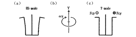
図11は本発明で利用する2つの振動モードを示す線画であって、(b)はTモード、(c)はHSモード、(a)はこれら両モードを90°位相差つきで同時に駆動した結果得られるドライブモード(T+HSモード)であり、両外脚先端が合成された円運動を行っている状態を示している。
【0021】
次に図12〜図14を用いて角速度の検出作用を説明する。各図の(a)は定常的に駆動されている基本的振動モードを互いの位相差には無関係に示し、各図(b)はそのモードに作用することが想定された角速度ωx、ωy、ωzを示し、各図(c)はそれによって生起するコリオリ力Fcx、Fcy、Fcz(各脚の振動の瞬時速度に比例し、速度と角速度とに直交する向きに現れる)と、それによって発生する、検出すべき振動モードを示している。
【0022】
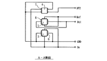
図1〜図3は本発明の振動ジャイロスコープの第1の実施の形態に関するもので、図1は振動体の電極膜を含めた平面図、図2はその電極配置と接続を示すA−A断面図、図3は励振および検出回路の構成を示すブロック図である。なお、既に述べた従来例と共通する事項については、重複する説明を以下省略する。
【0023】
図1および図2において、外脚3の電極膜6は脚の周囲4面に、外脚4の電極膜7は脚の上下2面のみにそれぞれ分割された形で、また中脚5の電極膜8は脚の周囲4面に設けられている。水晶材のZカット板においては、一般に外脚の上下面のみに脚の名が手方向に平行に分割して設けた電極膜はTモードの駆動・検出に適し、外脚の周囲4面に設けた電極膜はHSモードまたはHAモードの駆動・検出に適する。なお各電極膜の接続あるいは引出線のために振動体の表面に設けられる導体パターンは図示を省略する。
【0024】
図2、図3において、GndおよびRefは信号の基準電位を与える端子(Refの電位はGndと電源電位の中間とすることもあるが、本例ではGndと等しいとし、図3の回路図にはRef端子を示していない)、Drは駆動(励振)信号を回路側とやりとりする駆動端子、Dt1およびDt2はそれぞれコリオリ力による信号を含んだ検出端子である。また図3では基本的な回路ブロックのみを図示しており補正的に作用する回路は図示していない。また結線の矢印は信号の流れる方向を示している。回路動作は、2端子の発振回路11に接続された駆動端子DrとGndにより外脚3がHSモードで励振される。
【0025】
Tモードも両モードの僅かな周波数差によりほぼ90°位相差で同時に生起される。なおTモードはその共振周波数で生起されること、あるいは両モードにおいて振幅が同程度に得られることが望ましい。そのためには発振回路11から得られるHSモードの駆動出力を、同モードの振動位相に対してずらすような回路手段あるいは素子を発振回路周辺に適宜追加したり、両モードの共振周波数差を三脚音叉の設計によって調節したりすることが可能である。
【0026】
AGC回路12は発振回路11の駆動出力を制御し、基本振動の振幅を安定化させる。同期検波回路13xは中脚5の検出信号をDt1端子から得てこれに、AGC回路12から得た信号(必要に応じて位相をずらす)にて同期検波をかけ、図8の作用により角速度ωxに比例する出力ωxoutを得る。
また中脚5のDt1端子から得た検出信号は図10のように角速度ωzに関する振動成分を、ωxとは90°位相が異なる形で含んでいるので、この信号を同期検波回路13zによって、AGC回路12の信号を位相シフト回路15により90°ずれた同期検波信号を作成し、同期検波回路13zに与えて角速度ωzに比例する出力ωzoutを得る。
【0027】
また検出端子Dt2から得られる信号は、図9のωyに比例するTモード信号と駆動信号とを含んでいるので、まず差動増幅器14により両者の差をとった上でωxoutを得た場合と同様に同期検波回路13yを用いてωyoutを得ることができる。
【0028】
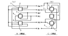
図4〜6は本発明の第2の実施の形態の電極配置、結線、および駆動・検出回路を示している。図4において三脚音叉1の表面(a)のみならず、軸Pに関して三脚音叉1を反転した裏面(b)を示している。また三脚音叉の対称軸(図示せず)に関して、両外脚の電極は、2面(上下のZ面)と周囲4面との2段の異なる配置を持っているので、それぞれ断面B−B、C−Cをとり、図5に結線を含めて図示した。断面B−Bの電極と断面C−Cの電極は一部で連続してつながっており、引回し用の電極パターンの簡素化が図られている。
【0029】
第2の実施の形態の特徴は、両外脚双方をTモードを駆動および検出できる電極を持つことであり、それ以外は第1の形態とほぼ同じ作用をする。従って図6の発振・検出回路の構成および作用は、その大部分は図3の回路と共通である。相違点は、Dt2、Dt3検出端子から得られた2脚の検出信号を加算回路16によって加算してから利用することである。
【0030】
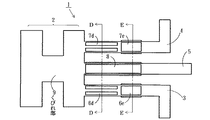
図7〜9は本発明の第3の実施の形態の電極配置、結線、および駆動・検出回路を示している。本実施の形態の特徴は、Tモード用の電極6d、7d(断面D−D部分)とHSモード用の電極6e、7e(断面E−E部分)を両外脚3、4の上で長手方向に分離して設けたことである。電極が多くなり引回しパターンが複雑化するが、例えば脚の先端側の電極6e、7eからの引出し線は脚の根元側の並列電極6d、7dの隙間を通すとか外脚の側面を利用して基部2側へ導くようにする。また脚の周囲に鉢巻き型の電極を設けて反対面の電極を接続したり、HS用電極とT用電極のGndラインを共通化して引出し線を減らすことができる。なお基部2内に設けたくびれ部9はTモード振動の生起を容易にするために設けたものである。
【0031】
そして駆動・検出回路(図9)では、Tモード用の電極6d、7d(GndおよびDr1端子)を直接発振回路11に接続してTモードの共振周波数(固有振動数)で励振させ、Tモードの駆動出力を駆動位相シフト回路17によってほぼ90°シフトしてHSモード用の電極6e、7e(Dr2端子)に供給し、HSモードもTモードの共振周波数で駆動するようにし、両モードで同等の振幅を得ようとしていることが特徴である。角速度の検出作用は他の実施の形態と同様であるが、図9の発振回路11はTモードを励振し、他の実施の形態の図3、図6における発振回路11はHSモードを励振していることから、それぞれの実施の形態においてAGC回路12より得られる駆動信号と、ある角速度成分を検出するに必要な同期検波信号との位相関係が90°異なる。それを考慮して位相シフト回路15の挿入位置が異なっている。
【0032】
上記各実施の形態では、単一の発振回路でHS、T両モードの基本振動を生起させたが、2つのモードの基本振動を別個の異なる周波数で駆動することも考えられる。図10は第4の実施の形態における駆動・検出回路のブロック図である。この実施の形態における振動体としては第3の実施の形態の振動体と同様に、HS、T両モードの駆動、検出電極がモード毎に設けられたものを用いる。図10においては各モードに対して異なる周波数で駆動する専用の発振回路を設けてあり、発振回路11aはDt1端子に接続されTモードを駆動する。また発振回路11bはDt2端子に接続されHSモードを駆動する。角速度の検出回路の構成は第3の実施の形態の回路部分と類似するが、同期検波用の信号をその角速度成分が利用する基本モードの駆動信号から得ている点が異なっている。
【0033】
本発明の実施の形態は既述の例に限られない。三脚音叉の形状寸法、振動体の材質(例えば他の圧電性結晶、圧電性磁器、金属に圧電素子を貼ったもの)を用いることができる。また電極膜や引出線の配置構造(例えばTモード用電極を脚の上下面〔Z面〕ではなく脚の左右面〔X面〕に設ける等)、更に駆動回路や検出回路の構成等に種々変更あるいは改善を図ることが許される。例えば任意の場所に小範囲の位相調節のための論理回路やL、C、R等のアナログ要素を挿入する、信号の適宜増幅を行う、フィルターを設ける。あるいはDt1、Dt2等の検出信号の一部をコリオリ力検出だけでなく、発振を助けるためのフィードバック信号として用いる(発振回路は3端子化する)等が考えられる。
【0034】
【発明の効果】
本発明においては、HSモードとTモードを組み合わせて用いたので2軸または3軸の角速度成分の検出が可能になった。また単一の周波数で駆動しても両モードについて十分大きな振幅が得られ、単純な構成で各軸の角速度に対して感度の高い多軸ジャイロスコープが得られる効果がある。また両モードにおいては中脚は原理的に不動なので、中脚を検出専用に用いることができ、回路構成を簡素化できる効果がある。
【図面の簡単な説明】
【図1】本発明の振動ジャイロスコープの第1の実施の形態における振動体の、電極膜を含めた平面図である。
【図2】本発明の第1の実施の形態における振動体の電極配置と接続を示す、図1におけるA−A断面図である。
【図3】本発明の第1の実施の形態における、励振および検出回路の構成を示すブロック図である。
【図4】本発明の振動ジャイロスコープの第2の実施の形態における振動体の、電極膜の配置を含めて示す平面図である。
【図5】本発明の第2の実施の形態における振動体の電極配置と接続を示す、図1におけるB−B断面図(a)およびC−C断面図(b)である。
【図6】本発明の第2の実施の形態における、励振および検出回路の構成を示すブロック図である。
【図7】本発明の振動ジャイロスコープの第3の実施の形態における振動体の、電極膜の配置を含めて示す平面図である。
【図8】本発明の第3の実施の形態における振動体の電極配置と接続を示す、図1におけるD−D断面図(a)およびE−E断面図(b)である。
【図9】本発明の第3の実施の形態における、励振および検出回路の構成を示すブロック図である。
【図10】本発明の第4の実施の形態における、励振および検出回路の構成を示すブロック図である。
【図11】本発明で用いる、三脚音叉の2種の振動モードを説明するための平面図的な模式図である。
【図12】駆動と検出の作用の関連を説明するための模式図であり、(a)はT駆動モード、(b)はそれに作用する角速度ωx、(c)はコリオリ力Fcxによって生起されるHA振動モードである。
【図13】駆動と検出の作用の関連を説明するための模式図であり、(a)はHS駆動モード、(b)はそれに作用する角速度ωy、(c)はコリオリ力Fcyによって生起されるT振動モードである。
【図14】駆動と検出の作用の関連を説明するための模式図であり、(a)はHS駆動モード、(b)はそれに作用する角速度ωz、(c)はコリオリ力Fczによって生起されるHA振動モードである。
【図15】従来例において、HSおよびVモードにおける外脚の振動変位と振動の位相差を駆動周波数に対して示したグラフである。
【図16】本発明において、HSおよびTモードにおける外脚の振動変位と振動の位相差を駆動周波数に対して示したグラフである。
【符号の説明】
1 三脚音叉
2 基部
3、4 外脚
5 中脚
6、7、7d、7e、8、8d、8e 電極膜
9 くびれ部
11、11a、11b 発振回路
12 AGC回路
13x、13y、13z 同期検波回路
14 差動増幅器
15 位相シフト回路
16 加算回路
17 駆動位相シフト回路
Dr、Dr1、Dr2 駆動端子
Dt1、Dt2 検出端子
Gnd、Ref 基準端子
E 電界
Fcx、Fcy、Fcz コリオリ力
u3、u4、u5 脚の速度成分
X、Y、Z 座標軸[0001]
TECHNICAL FIELD OF THE INVENTION
The present invention relates to a vibratory gyroscope. More specifically, the present invention relates to a multi-axis vibratory gyroscope using a tripod type tuning fork. Note that a tripod-type tuning fork refers to a vibrating body that includes three cantilevered vibrating bodies protruding in the same direction substantially in parallel from a common base and configured to support using the base. And
[0002]
[Prior art]
The material and shape of the tripod tuning fork are substantially common to the present invention and the prior art, and have a general shape as shown in the plan view of FIG. (However, the shape of the electrode film varies depending on the purpose.) In the figure,
[0003]
[0004]
Next, a basic (lowest order) vibration mode that can occur in a tripod tuning fork will be described. There are four types: (1) HS mode in which both
[0005]
The operation of the vibratory gyroscope using a tripod type tuning fork will be briefly described. When the tripod tuning fork is vibrating constantly in any of the above vibration modes and the entire vibration system is rotated around a certain rotation axis at a certain angular velocity, the Coriolis acceleration causes an apparent force on the vibrating mass. Occurs. The magnitude and direction of the Coriolis force is twice the vector product of the angular velocity and the momentum of the oscillating mass. The Coriolis force is generated in each of the vibrating legs, and the phase thereof coincides with the vibration speed, so that the vibration displacement is shifted by 90 °. Therefore, if the vibrations of each leg are detected in a piezoelectric manner by appropriately combining them and the detection output is rectified by the synchronous detection means in consideration of the phase, the Coriolis force, that is, the components ωx, ωy, ωz of the angular velocity in the direction of the vibration body coordinate axis are obtained. A proportional direct current is obtained.
[0006]
[Problems to be solved by the invention]
In a conventional vibrating gyroscope (for example, using a bar-shaped vibrating body or a two-legged tuning fork), the angular velocity that can be detected by one vibrating body is one direction (one axis). The vibrator can detect two- or three-axis angular velocity components. This is desirable because it is extremely effective in increasing the number of functions, miniaturization, and cost reduction of the vibration gyroscope itself and the device in which it is incorporated.
[0007]
In order to detect a multi-axis angular velocity component, not one vibration mode for applying the angular velocity is excited but a plurality of vibration modes, and the distortion of the vibration due to the Coriolis force generated in each vibration mode is detected. The phases of a plurality of vibration modes to be excited are shifted so that the distortion effect due to each vibration mode can be detected separately. In the proposed conventional example, the HS mode and the V mode are excited with a phase shift of 90 °. As a result, the tips of the outer legs perform a circular motion or an elliptical motion. When ωx acts on the V mode, the amplitude of the HS mode changes due to the Coriolis force Fcx, and when ωy acts on the V mode, the HA mode is generated by the Coriolis force Fcy and the middle leg vibrates. When ωz acts on the HS mode, the Coriolis force Fcz also generates the HA mode, and the middle leg vibrates. The signals of the middle legs in the latter two HA modes are separated by performing synchronous detection of two systems with shifted phases with respect to the detection signals of the middle legs using the phase difference between the basic V and HS modes. .
[0008]
However, it was later found that the above-mentioned conventional example had a drawback. In general, in order to excite the two modes with phases shifted from each other, it is conceivable to provide an appropriate difference between the natural frequencies of the two modes and to excite them at one or an intermediate frequency. FIG. 14 shows an example of a tripod tuning fork (made of quartz, the basic dimensions of each part are in mm, the plate thickness z = 0.3, the base x = 2.1, y-4.0, the width x of both outer legs and slits) = 0.3, 4.2 from the slit bottom to the tip of the outer leg, x = 0.8 from the slit surface of the bent portion to the tip, and the width of the bent portion y = 0.3). This is a result of a simulation, in which vibration displacement (tip amplitude) ux (HS mode) and ui (V mode) of one outer leg, and a phase difference between the two are plotted with respect to a frequency change.
[0009]
From FIG. 15, it was found that the vibration displacement in the HS mode was extremely smaller than that in the T mode (almost 1/10) at the frequency at which the phase difference between the two modes was 90 °. (Even when the frequency difference was given by changing the other parameters, the result was almost the same.) When the frequencies of both modes were made closer, the amplitude difference was reduced, but the frequency difference was limited to almost 50 Hz. This is because both modes are coupled modes, so circular motion of the outer leg or elliptical motion close to a circle cannot be obtained, the difference in angular velocity sensitivity between both modes is large, and a high-sensitivity multi-axis gyroscope is It is shown that it is difficult to realize by a method of self-oscillating both the HS mode and the V mode at the frequency of.
[0010]
An object of the present invention is to provide a multi-axis vibratory gyroscope with high sensitivity by combining an improved vibration mode in a gyroscope using a tripod tuning fork as a vibrator. Yet another object is to provide an excitation technique for the vibration mode.
[0011]
[Means for Solving the Problems]
In order to achieve the above object, a vibration gyroscope of the present invention has the following features.
(1) An outline of a tripod-type tuning fork having three substantially parallel vibrating legs is provided. The Z-axis extends in a direction perpendicular to the tripod surface, the Y-axis extends in a direction parallel to the tuning-fork axis, and the Z-axis and the Y-axis. When the X-axis is taken in a direction perpendicular to the direction, the HS mode in which both outer legs are simultaneously opened and closed in the X direction, the T mode in which both outer legs are displaced in the opposite direction in the Z direction, and the outer legs in the X direction are the same. A vibrating body having an HA mode in which the center leg is displaced in the opposite direction and the center leg is displaced in the opposite direction, a driving circuit means for vibrating the two modes, and a rotational motion acting on the vibrating body. Coriolis force detecting means for detecting distortion generated in each of the vibrating legs due to Coriolis force.
[0012]
The vibration gyroscope of the present invention may further have the following features.
(2) One oscillation circuit is provided for driving the HS mode and the T mode at the same frequency.
[0013]
In order to achieve the above object, a vibration gyroscope of the present invention has the following features.
(3) A tripod-type tuning fork having three substantially parallel vibrating legs is formed. The Z-axis extends in a direction perpendicular to the tripod surface, the Y-axis extends in a direction parallel to the tuning-fork axis, and the Z-axis and the Y-axis. When the X-axis is taken in a direction perpendicular to the direction, the HS mode in which both outer legs are simultaneously opened and closed in the X direction, the T mode in which both outer legs are displaced in the opposite direction in the Z direction, and the outer legs in the X direction are the same. And the middle leg is displaced in the opposite direction as a possible vibration mode. The HS mode and the T mode both have a vibrating body given a predetermined natural frequency close to each other. Drive circuit means for oscillating the modes while maintaining a phase difference of about 90 ° from each other, and Coriolis force for detecting distortion generated in the three vibrating legs due to Coriolis force generated by rotational movement acting on the vibrating body Detecting means, wherein the Coriolis force detecting means is a T mode First detection circuit means for detecting the vibration of the HA mode caused by ωx acting, second detection circuit means for detecting a change in the T mode caused by ωy acting on the HS mode, and action on the HS mode And at least two of the third detection circuit means for detecting the HA mode vibration caused by ωz.
[0014]
The vibration gyroscope of the present invention may further include at least one of the following features.
(4) The excitation circuit means has a circuit configuration for exciting the HS mode, and the T mode is automatically given a natural frequency slightly different from that of the HS mode, so that the T mode automatically has a phase difference of about 90 °. Be driven
[0015]
(5) The excitation circuit means includes an oscillation circuit for exciting the T mode (or HS mode) and a circuit means for generating an excitation output having a phase substantially 90 ° different from the excitation output of the T mode (or HS mode). Driving the HS mode (or T mode) with the latter excitation output.
[0016]
(6) The detection circuit means includes the first detection circuit means and the second detection circuit means using an HA mode generated by different angular velocities ωx and ωz, and the first detection circuit means and the second detection circuit means The second detection circuit means separates and detects ωx and ωz by performing synchronous detection with a phase shift of 90 ° from each other.
[0017]
(7) The piezoelectric material of the vibrator is quartz.
[0018]
BEST MODE FOR CARRYING OUT THE INVENTION
First, the principle operation of the present invention and its advantages will be comprehensively described.
In the present invention, the HS mode and the T mode are used in combination for driving a tripod tuning fork. (Referred to as HS + T mode) FIG. 16 is a graph of a forced vibration response simulation showing the phase difference between the vibration displacement and vibration of the outer leg in the HS and T modes with respect to the drive frequency. In this example, the width of both outer legs was x = 0.275 mm (the length of the middle leg was y = 4.3 mm, and the other basic dimensions were the same as the conventional example).
[0019]
As shown in FIG. 16, in this example, the frequencies of both modes could be made very close. This is because both modes are not combined modes. In addition, it was found that a driving frequency at which the vibration displacements ux and uz are substantially equal exists near the T-mode resonance point at a phase difference of 90 °. In addition, the magnitude of the vibration displacement at that point is about 35 times larger than that of the conventional HS mode and about 5.5 times larger than the conventional V mode of the T mode, and the vibration trajectory of the outer leg is also a circular motion. And became extremely advantageous for improving the detection sensitivity.
[0020]
FIG. 11 is a line drawing showing two vibration modes used in the present invention. FIG. 11 (b) shows a T mode, FIG. 11 (c) shows an HS mode, and FIG. The resulting drive mode (T + HS mode) shows a state in which the ends of both outer legs are performing a combined circular motion.
[0021]
Next, the detection operation of the angular velocity will be described with reference to FIGS. (A) of each figure shows a fundamental vibration mode that is driven steadily irrespective of the phase difference, and (b) of each figure shows angular velocities ωx, ωy, supposed to act on that mode. ωz, and each figure (c) shows the resulting Coriolis forces Fcx, Fcy, Fcz (proportional to the instantaneous speed of the vibration of each leg and appears in a direction orthogonal to the speed and the angular speed) and generated by them. , A vibration mode to be detected.
[0022]
1 to 3 relate to a first embodiment of the vibrating gyroscope of the present invention. FIG. 1 is a plan view including an electrode film of a vibrating body, and FIG. 2 is an AA showing its electrode arrangement and connection. FIG. 3 is a block diagram showing a configuration of the excitation and detection circuit. Note that, for items common to the above-described conventional example, redundant description will be omitted below.
[0023]
1 and 2, the
[0024]
In FIG. 2 and FIG. 3, Gnd and Ref are terminals for applying a signal reference potential (the potential of Ref may be intermediate between Gnd and the power supply potential, but in this example, it is assumed to be equal to Gnd, and in the circuit diagram of FIG. Denotes a Ref terminal), Dr denotes a drive terminal for exchanging a drive (excitation) signal with the circuit side, and Dt1 and Dt2 denote detection terminals each containing a signal due to Coriolis force. FIG. 3 shows only basic circuit blocks, and does not show circuits that act as corrections. The connection arrows indicate the direction in which the signal flows. In the circuit operation, the
[0025]
The T mode is also generated simultaneously with a phase difference of approximately 90 ° due to a slight frequency difference between the two modes. Note that it is desirable that the T mode be generated at the resonance frequency or that the amplitude be obtained in both modes at the same level. For this purpose, a circuit means or an element for shifting the HS mode drive output obtained from the
[0026]
The
Since the detection signal obtained from the Dt1 terminal of the
[0027]
Since the signal obtained from the detection terminal Dt2 includes a T-mode signal and a drive signal proportional to ωy in FIG. 9, first, the difference between the two is obtained by the
[0028]
4 to 6 show an electrode arrangement, connection, and a drive / detection circuit according to a second embodiment of the present invention. FIG. 4 shows not only the front surface (a) of the
[0029]
The feature of the second embodiment resides in that both outer legs have electrodes capable of driving and detecting the T mode, and otherwise operates substantially the same as the first embodiment. Therefore, the configuration and operation of the oscillation / detection circuit of FIG. 6 are substantially the same as those of the circuit of FIG. The difference is that the detection signals of the two legs obtained from the Dt2 and Dt3 detection terminals are added by the
[0030]
FIGS. 7 to 9 show an electrode arrangement, connection, and a drive / detection circuit according to a third embodiment of the present invention. The feature of the present embodiment is that the
[0031]
In the drive / detection circuit (FIG. 9), the T-
[0032]
In each of the above embodiments, the single oscillation circuit generates the fundamental vibration in both the HS mode and the T mode. However, the fundamental vibration in the two modes may be driven at different frequencies. FIG. 10 is a block diagram of a drive / detection circuit according to the fourth embodiment. As the vibrating body in this embodiment, similarly to the vibrating body of the third embodiment, a vibrating body provided with driving and detecting electrodes in both the HS and T modes for each mode is used. In FIG. 10, a dedicated oscillation circuit for driving each mode at a different frequency is provided, and the oscillation circuit 11a is connected to the Dt1 terminal and drives the T mode. The oscillation circuit 11b is connected to the Dt2 terminal and drives the HS mode. The configuration of the angular velocity detection circuit is similar to that of the circuit part of the third embodiment, except that a signal for synchronous detection is obtained from the fundamental mode drive signal used by the angular velocity component.
[0033]
Embodiments of the present invention are not limited to the examples described above. The shape and dimensions of the tripod tuning fork and the material of the vibrating body (for example, another piezoelectric crystal, piezoelectric porcelain, or metal with a piezoelectric element attached thereto) can be used. Also, various arrangement structures of the electrode film and the lead lines (for example, the T-mode electrodes are provided on the left and right sides (X plane) of the leg instead of the upper and lower surfaces [Z plane]), and further the configuration of the drive circuit and the detection circuit are various. Changes or improvements are allowed. For example, a filter for inserting a logic circuit for phase adjustment in a small range or an analog element such as L, C, or R at an arbitrary position and appropriately amplifying a signal is provided. Alternatively, not only detection of Coriolis force but also use of a part of the detection signals such as Dt1 and Dt2 as a feedback signal for assisting oscillation (the oscillation circuit may have three terminals) may be considered.
[0034]
【The invention's effect】
In the present invention, since the HS mode and the T mode are used in combination, it is possible to detect angular velocity components of two or three axes. Further, even when driven at a single frequency, a sufficiently large amplitude is obtained in both modes, and there is an effect that a multi-axis gyroscope having a simple configuration and high sensitivity to the angular velocity of each axis can be obtained. In addition, since the middle leg is not moved in principle in both modes, the middle leg can be used exclusively for detection, and the circuit configuration can be simplified.
[Brief description of the drawings]
FIG. 1 is a plan view including an electrode film of a vibrating body according to a first embodiment of a vibration gyroscope of the present invention.
FIG. 2 is a sectional view taken along the line AA in FIG. 1, showing electrode arrangement and connection of the vibrating body according to the first embodiment of the present invention.
FIG. 3 is a block diagram illustrating a configuration of an excitation and detection circuit according to the first embodiment of the present invention.
FIG. 4 is a plan view showing the vibrating body according to a second embodiment of the vibrating gyroscope of the present invention, including the arrangement of electrode films.
FIGS. 5A and 5B are a sectional view taken along the line BB and a sectional view taken along the line CC in FIG. 1, showing electrode arrangement and connection of the vibrating body according to the second embodiment of the present invention.
FIG. 6 is a block diagram illustrating a configuration of an excitation and detection circuit according to a second embodiment of the present invention.
FIG. 7 is a plan view showing a vibrating body according to a third embodiment of the vibration gyroscope of the present invention, including an arrangement of electrode films.
8A and 8B are a sectional view taken along the line DD and a sectional view taken along the line EE in FIG. 1, showing the arrangement and connection of electrodes of the vibrating body according to the third embodiment of the present invention.
FIG. 9 is a block diagram illustrating a configuration of an excitation and detection circuit according to a third embodiment of the present invention.
FIG. 10 is a block diagram illustrating a configuration of an excitation and detection circuit according to a fourth embodiment of the present invention.
FIG. 11 is a schematic plan view for explaining two vibration modes of a tripod tuning fork used in the present invention.
FIGS. 12A and 12B are schematic diagrams for explaining the relationship between the driving and the detecting operation, wherein FIG. 12A is a T driving mode, FIG. 12B is an angular velocity ωx acting on the driving mode, and FIG. 12C is generated by a Coriolis force Fcx. This is the HA vibration mode.
FIGS. 13A and 13B are schematic diagrams for explaining the relationship between the driving and the detecting operation. FIG. 13A shows the HS driving mode, FIG. 13B shows the angular velocity ωy acting on the driving mode, and FIG. 13C shows the angular velocity ωy generated by the Coriolis force Fcy. This is the T vibration mode.
FIGS. 14A and 14B are schematic diagrams for explaining the relationship between the drive and the detection operation, wherein FIG. 14A is an HS drive mode, FIG. 14B is an angular velocity ωz acting on the drive mode, and FIG. 14C is generated by a Coriolis force Fcz. This is the HA vibration mode.
FIG. 15 is a graph showing the phase difference between the vibration displacement and the vibration of the outer leg in the HS and V modes with respect to the driving frequency in the conventional example.
FIG. 16 is a graph showing the phase difference between the vibration displacement and the vibration of the outer leg in the HS and T modes with respect to the drive frequency in the present invention.
[Explanation of symbols]
DESCRIPTION OF
Claims (7)
Priority Applications (1)
| Application Number | Priority Date | Filing Date | Title |
|---|---|---|---|
| JP2003165768A JP2004333460A (en) | 2003-05-08 | 2003-05-08 | Oscillating gyroscope |
Applications Claiming Priority (1)
| Application Number | Priority Date | Filing Date | Title |
|---|---|---|---|
| JP2003165768A JP2004333460A (en) | 2003-05-08 | 2003-05-08 | Oscillating gyroscope |
Publications (1)
| Publication Number | Publication Date |
|---|---|
| JP2004333460A true JP2004333460A (en) | 2004-11-25 |
Family
ID=33508866
Family Applications (1)
| Application Number | Title | Priority Date | Filing Date |
|---|---|---|---|
| JP2003165768A Pending JP2004333460A (en) | 2003-05-08 | 2003-05-08 | Oscillating gyroscope |
Country Status (1)
| Country | Link |
|---|---|
| JP (1) | JP2004333460A (en) |
Cited By (5)
| Publication number | Priority date | Publication date | Assignee | Title |
|---|---|---|---|---|
| JP2008224628A (en) * | 2007-03-15 | 2008-09-25 | Sony Corp | Angular velocity sensor and electronic device |
| JP2008249489A (en) * | 2007-03-30 | 2008-10-16 | Tdk Corp | Angular velocity sensor element and angular velocity sensor device |
| US7714486B2 (en) | 2007-03-30 | 2010-05-11 | Tdk Corporation | Angular velocity sensor and angular velocity sensing device |
| US7934422B2 (en) | 2007-03-30 | 2011-05-03 | Tdk Corporation | Angular velocity sensor and angular velocity sensing device |
| US7975546B2 (en) | 2006-12-25 | 2011-07-12 | Tdk Corporation | Angular velocity sensor and angular velocity sensing device |
-
2003
- 2003-05-08 JP JP2003165768A patent/JP2004333460A/en active Pending
Cited By (6)
| Publication number | Priority date | Publication date | Assignee | Title |
|---|---|---|---|---|
| US7975546B2 (en) | 2006-12-25 | 2011-07-12 | Tdk Corporation | Angular velocity sensor and angular velocity sensing device |
| JP2008224628A (en) * | 2007-03-15 | 2008-09-25 | Sony Corp | Angular velocity sensor and electronic device |
| JP2008249489A (en) * | 2007-03-30 | 2008-10-16 | Tdk Corp | Angular velocity sensor element and angular velocity sensor device |
| US7714486B2 (en) | 2007-03-30 | 2010-05-11 | Tdk Corporation | Angular velocity sensor and angular velocity sensing device |
| US7934422B2 (en) | 2007-03-30 | 2011-05-03 | Tdk Corporation | Angular velocity sensor and angular velocity sensing device |
| US8056414B2 (en) | 2007-03-30 | 2011-11-15 | Tdk Corporation | Angular velocity sensor and angular velocity sensing device |
Similar Documents
| Publication | Publication Date | Title |
|---|---|---|
| JP2006201118A (en) | Piezoelectric vibrating gyroscope element and gyro sensor | |
| JP2005249646A (en) | Tuning fork type oscillator for angular velocity sensor, angular velocity sensor using the oscillator, and automobile using the angular velocity sensor | |
| JP2006170860A (en) | Piezoelectric gyro element, and piezoelectric gyroscope | |
| JP4911690B2 (en) | Vibrating gyro vibrator | |
| JP2000074673A (en) | Compound movement sensor | |
| JP2004333460A (en) | Oscillating gyroscope | |
| JPH1194557A (en) | Oscillation gyro | |
| JPH08278146A (en) | Vibrating gyro | |
| JPH02218914A (en) | Vibrating gyroscope | |
| JP4514115B2 (en) | Angular velocity sensor | |
| JP2006267094A (en) | Inertial sensor element | |
| JP2004101392A (en) | Dual tuning fork type vibration gyroscopic sensor | |
| JP2006010408A (en) | Vibratory gyro | |
| JP2006145420A (en) | Angular speed detection system | |
| JP2006266969A (en) | Tuning fork type piezo-electric oscillating gyroscope | |
| JP4163031B2 (en) | Tuning fork type angular velocity sensor | |
| JP2002213963A (en) | Vibration gyroscope | |
| JP3323361B2 (en) | Vibratory gyroscope | |
| JP2008145325A (en) | Vibration gyro | |
| JP2010096695A (en) | Vibration gyroscope | |
| JP2008175679A (en) | Vibration gyro | |
| JP2006029901A (en) | Driver circuity of oscillating gyroscope | |
| JP4183272B2 (en) | Angular velocity sensor and measuring method of angular velocity | |
| JP4345130B2 (en) | Vibrating gyro | |
| JP2009192403A (en) | Angular velocity and acceleration detector |
Legal Events
| Date | Code | Title | Description |
|---|---|---|---|
| A621 | Written request for application examination |
Free format text: JAPANESE INTERMEDIATE CODE: A621 Effective date: 20060501 |
|
| A977 | Report on retrieval |
Free format text: JAPANESE INTERMEDIATE CODE: A971007 Effective date: 20080530 |
|
| A131 | Notification of reasons for refusal |
Free format text: JAPANESE INTERMEDIATE CODE: A131 Effective date: 20080610 |
|
| A02 | Decision of refusal |
Free format text: JAPANESE INTERMEDIATE CODE: A02 Effective date: 20081021 |