JP2004332878A - Control device of continuously variable transmission - Google Patents
Control device of continuously variable transmission Download PDFInfo
- Publication number
- JP2004332878A JP2004332878A JP2003132222A JP2003132222A JP2004332878A JP 2004332878 A JP2004332878 A JP 2004332878A JP 2003132222 A JP2003132222 A JP 2003132222A JP 2003132222 A JP2003132222 A JP 2003132222A JP 2004332878 A JP2004332878 A JP 2004332878A
- Authority
- JP
- Japan
- Prior art keywords
- change rate
- speed ratio
- continuously variable
- theoretical
- variable transmission
- Prior art date
- Legal status (The legal status is an assumption and is not a legal conclusion. Google has not performed a legal analysis and makes no representation as to the accuracy of the status listed.)
- Pending
Links
Images

Abstract
Description
【0001】
【発明の属する技術分野】
この発明は、変速比を連続的に変化させることのできる無段変速機を対象とする制御装置に関し、特に無段変速機の滑りを検出する装置に関するものである。
【0002】
【従来の技術】
ベルト式無段変速機やトラクション式無段変速機は、ベルトとプーリとの間の摩擦力や、ディスクとローラとの間のトラクションオイルのせん断力を利用してトルクを伝達している。したがってそのトルク容量を超えるトルクが作用した場合には、ベルトとプーリとの間、あるいはディスクとローラとの間で滑りが生じる。無段変速機に滑りが生じた場合には、その滑りを解消するための操作をおこなう必要があり、またトルク容量を設定する挟圧力を可及的に低下させるために、入力トルクに対して滑りの生じるいわゆる限界挟圧力を検出する際に滑りを生じさせる場合がある。
【0003】
このように無段変速機における滑りの検出は、無段変速機の制御上、必ず検出する必要がある。無段変速機における滑りは、いずれかの部材の回転速度の変化として現れるから、変速比や変速速度の変化によって滑りを検出することができる。すなわち、滑りの生じていない状態を表すいわゆる基準となる値を定めておき、常時検出している値とそのいわゆる基準値と比較することにより、無段変速機の滑りを検出することができる。
【0004】
そのいわゆる基準となる値として、従来、理論変速比変化率を設定し、入力回転速度と出力回転速度とに基づいて求められる実変速比変化率をその理論変速比変化率と比較し、その比較結果に基づいて滑りを検出することが特許文献1に記載されている。そして、この特許文献1に記載された装置では、滑りを検出することに基づいてライン圧を学習するように構成されている。さらに従来、ベルト式無段変速機におけるベルトの圧着力の変化によってスリップ限界を決定し、スリップを生じさせなようにするために、検出されたスリップ限界を超えないように圧着力を調整する装置が、特許文献2に記載されている。
【0005】
【特許文献1】
特開平6−11022号公報(段落(0126)〜(0131))
【特許文献2】
特開2001−12593号公報(要約、請求項1,2、段落(0013)、図4)
【0006】
【発明が解決しようとする課題】
上記の特許文献1に記載されている発明では、変速比が変速比制御弁流量で制御され、かつベルトの周長が一定であることを利用して、単位時間あたりの変速比の変化率を求めている。より具体的には、駆動プーリ側の油圧アクチュエータにおける容積によって変速比を微分し(すなわち、変速比の微小変化量と容積の微小変化量との比を求め)、これに変速比制御弁での流量を掛けて、単位時間あたりの理論変速比変化率を算出している。したがって所定時間の間での理論変速比変化率は、その単位時間あたりの値を積分して算出している。
【0007】
そのため、従来では、特許文献1に記載されているように、理論変速比変化率を求める演算が複雑であり、そのために、滑り検出制御に遅れや誤差が生じる可能性があった。また、理論変速比変化率を求めるために積分操作をおこなうので、その演算を継続し、あるいは繰り返しおこなった場合に、その積分操作に不可避的に介在する誤差が蓄積して、滑りの検出精度が低下する可能性がある。さらに、変速比制御弁での流量を用いて理論変速比変化率を演算するので、変速比制御弁での流量の誤差が、理論変速比変化率の演算精度、ひいては滑りの検出精度に影響し、その検出精度が低下する可能性がある。
【0008】
この発明は上記の技術的課題に着目してなされたものであり、理論変速比変化率を用いて、容易かつ高精度に滑りを検出することのできる制御装置を提供することを目的とするものである。
【0009】
【課題を解決するための手段およびその作用】
上記の目的を達成するために、請求項1の発明は、駆動プーリと従動プーリとに巻き掛けたベルトを各プーリに軸線方向の推力を付与して挟み付け、そのベルトのいずれかのプーリに対する滑りを、理論変速比変化率と入力回転速度および出力回転速度から求まる実変速比変化率とに基づいて検出する無段変速機の制御装置において、理論変速比変化率が前記推力の変化量に比例する計算モデルに基づいて前記理論変速比変化率を算出する理論変速比変化率算出手段を備えていることを特徴とする制御装置である。
【0010】
したがって請求項1の発明では、変速比を設定するいずれか一方のプーリにおける推力の変化に理論変速比変化率が比例する計算モデルに基づいて、理論変速比変化率が求められる。そして、入力回転速度と出力回転速度とから求められる実変速比変化率と上記の理論変速比変化率とが比較されて、無段変速機での滑りが検出される。そのため、理論変速比変化率の算出が容易になり、無段変速機での滑りが迅速に、また精度良く検出される。
【0011】
また、請求項2の発明は、理論変速比変化率と入力回転速度および出力回転速度から求まる実変速比変化率との比較結果に基づいて滑りを検出する無段変速機の制御装置において、変速比を制御する変速比制御弁の動作特性を学習する学習手段と、前記理論変速比変化率と実変速比変化率との比較結果に基づいて滑りを判断する判断基準を、前記学習手段による学習の前後で変更する滑り判断基準設定手段とを備えていることを特徴とする制御装置である。
【0012】
したがって請求項2の発明では、変速比制御弁の動作特性が学習され、その学習の前後で、前記滑り判断基準が変更される。そのため、変速比制御弁の動作特性が、理論変速比変化率と実変速比変化率との比較による滑りの判断に反映される。すなわち、変速比制御弁の動作特性に影響を受ける理論変速比変化率が滑りの判断に使用されているのに対して、その変速比制御弁の動作特性が滑り判断基準に反映させられるので、滑りの判断あるいは検出の精度が向上する。
【0013】
さらに、請求項3の発明は、挟圧力によってトルク容量が変化する無段変速機の理論変速比変化率と入力回転速度および出力回転速度から求まる実変速比変化率とを比較して滑りを検出する無段変速機の制御装置において、変速比を制御する変速比制御弁の動作特性を学習する学習手段と、その学習手段による学習が終了した後に、前記挟圧力を低下させ、かつ挟圧力の低下に伴う滑りを検出する滑り検出手段とを備えていることを特徴とする制御装置である。
【0014】
したがって請求項3の発明では、変速比制御弁の動作特性が学習された後、すなわち変速比制御弁の動作特性が制御データとして取り込むことが可能になっ後に、挟圧力を低下させるとともに、挟圧力の低下に伴う滑りを検出する制御が実行される。そのため、変速比制御弁の動作特性を反映させることにより、変速比制御弁の動作特性が要因となる誤差を排除した状態での制御が可能になり、その結果、無段変速機での滑りの検出が迅速かつ精度良くおこなわれる。
【0015】
そして、請求項4の発明は、積分操作を含む演算で求められる理論変速比変化率と入力回転速度および出力回転速度から求まる実変速比変化率との比較結果に基づいて滑りを検出する無段変速機の制御装置において、前記無段変速機に作用するトルクが安定している予め定めた所定の状態で、前記理論変速比変化率の演算の初期値を更新する初期化手段を備えていることを特徴とする制御装置である。
【0016】
したがって請求項4の発明では、理論変速比変化率の演算のための初期値が、トルクの安定している所定の状態で更新されるので、積分操作をおこなうとしても、誤差の累積などの誤差要因が抑制され、その結果、理論変速比変化率を使用した滑りの検出精度が向上する。
【0017】
【発明の実施の形態】
つぎにこの発明を具体例に基づいて説明する。先ず、この発明で対象とする無段変速機を含む駆動系統の一例を説明すると、図5は、ベルト式無段変速機1を含む駆動機構を模式的に示しており、その無段変速機1は、前後進切換機構2およびロックアップクラッチ3付きの流体伝動機構4を介して動力源5に連結されている。
【0018】
その動力源5は、内燃機関、あるいは内燃機関と電動機、もしくは電動機などによって構成されている。なお、以下の説明では、動力源5をエンジン5と記す。また、流体伝動機構4は、例えば従来のトルクコンバータと同様の構成であって、エンジン5によって回転させられるポンプインペラとこれに対向させて配置したタービンランナーと、これらの間に配置したステータとを有し、ポンプインペラで発生させたフルードの螺旋流をタービンランナーに供給することよりタービンランナーを回転させ、トルクを伝達するように構成されている。
【0019】
このような流体を介したトルクの伝達では、ポンプインペラとタービンランナーとの間に不可避的な滑りが生じ、これが動力伝達効率の低下要因となるので、ポンプインペラなどの入力側の部材とタービンランナーなどの出力側の部材とを直接連結するロックアップクラッチ3が設けられている。このロックアップクラッチ3は、油圧によって制御するように構成され、完全係合状態および完全解放状態、ならびにこれらの中間の状態であるスリップ状態に制御され、さらにそのスリップ回転数を適宜に制御できるようになっている。
【0020】
前後進切換機構2は、エンジン5の回転方向が一方向に限られていることに伴って採用されている機構であって、入力されたトルクをそのまま出力し、また反転して出力するように構成されている。図5に示す例では、前後進切換機構2としてダブルピニオン型の遊星歯車機構が採用されている。すなわち、サンギヤ6と同心円上にリングギヤ7が配置され、これらのサンギヤ6とリングギヤ7との間に、サンギヤ6に噛合したピニオンギヤ8とそのピニオンギヤ8およびリングギヤ7に噛合した他のピニオンギヤ9とが配置され、これらのピニオンギヤ8,9がキャリヤ10によって自転かつ公転自在に保持されている。そして、二つの回転要素(具体的にはサンギヤ6とキャリヤ10と)を一体的に連結する前進用クラッチ11が設けられ、またリングギヤ7を選択的に固定することにより、出力されるトルクの方向を反転する後進用ブレーキ12が設けられている。
【0021】
無段変速機1は、従来知られているベルト式無段変速機と同じ構成であって、互いに平行に配置された駆動プーリ13と従動プーリ14とのそれぞれが、固定シーブと、油圧式のアクチュエータ15,16によって軸線方向に前後動させられる可動シーブとによって構成されている。したがって各プーリ13,14の溝幅が、可動シーブを軸線方向に移動させることにより変化し、それに伴って各プーリ13,14に巻掛けたベルト17の巻掛け半径(プーリ13,14の有効径)が連続的に変化し、変速比が無段階に変化するようになっている。そして、上記の駆動プーリ13が前後進切換機構2における出力要素であるキャリヤ10に連結されている。
【0022】
なお、従動プーリ14における油圧アクチュエータ16には、無段変速機1に入力されるトルクに応じた油圧(ライン圧もしくはその補正圧)が、図示しない油圧ポンプおよび油圧制御装置を介して供給されている。したがって、従動プーリ14における各シーブがベルト17を挟み付けることにより、ベルト17に張力が付与され、各プーリ13,14とベルト17との挟圧力(接触圧力)が確保されるようになっている。
【0023】
これに対して駆動プーリ13における油圧アクチュエータ15には、アップシフト用の変速比制御弁とダウンシフト用の変速比制御弁(それぞれ図示せず)とが接続されている。そして、入力回転数を目標回転数に一致させるフィードバック制御によっていずれかの変速比制御弁をデューティ制御することにより、油圧アクチュエータ15に圧油が給排され、所定の変速比に応じた溝幅(有効径もしくは巻掛け径)に設定するようになっている。これら各プーリ13,14における可動シーブを軸線方向に押圧する力が推力であり、したがってその推力は、各油圧アクチュエータ15,16に供給されている圧油や遠心力、さらにはリターンスプリングなどの弾性力によって生じる。
【0024】
上記の従動プーリ14が、ギヤ対18を介してディファレンシャル19に連結され、このディファレンシャル19から駆動輪20にトルクを出力するようになっている。したがって上記の駆動機構では、エンジン5と駆動輪20との間に、ロックアップクラッチ3と無段変速機1とが直列に配列されている。
【0025】
上記の無段変速機1およびエンジン5を搭載した車両の動作状態(走行状態)を検出するために各種のセンサーが設けられている。すなわち、無段変速機1に対する入力回転数(前記タービンランナーの回転数)を検出して信号を出力するタービン回転数センサー21、駆動プーリ13の回転数を検出して信号を出力する入力回転数センサー22、従動プーリ14の回転数を検出して信号を出力する出力回転数センサー23、ベルト挟圧力を設定するための従動プーリ14側の油圧アクチュエータ16の圧力を検出する油圧センサー24が設けられている。また、特には図示しないが、アクセルペダルの踏み込み量を検出して信号を出力するアクセル開度センサー、スロットルバルブの開度を検出して信号を出力するスロットル開度センサー、ブレーキペダルが踏み込まれた場合に信号を出力するブレーキセンサーなどが設けられている。
【0026】
上記の前進用クラッチ11および後進用ブレーキ12の係合・解放の制御、および前記ベルト17の挟圧力の制御、ならびに変速比の制御、さらにはロックアップクラッチ3の制御をおこなうために、変速機用電子制御装置(CVT−ECU)25が設けられている。この電子制御装置25は、一例としてマイクロコンピュータを主体として構成され、入力されたデータおよび予め記憶しているデータに基づいて所定のプログラムに従って演算をおこない、前進や後進あるいはニュートラルなどの各種の状態、および要求される挟圧力の設定、ならびに変速比の設定、ロックアップクラッチ3の係合・解放ならびにスリップ回転数などの制御を実行するように構成されている。
【0027】
ここで、変速機用電子制御装置25に入力されているデータ(信号)の例を示すと、無段変速機1の入力回転数(入力回転速度)Ninの信号、無段変速機1の出力回転数(出力回転速度)No の信号が、それぞれに対応するセンサから入力されている。また、エンジン5を制御するエンジン用電子制御装置(E/G−ECU)26からは、エンジン回転数Ne の信号、エンジン(E/G)負荷の信号、アクセルペダル(図示せず)の踏み込み量であるアクセル開度信号などが入力されている。
【0028】
無段変速機1によれば、入力回転数であるエンジン回転数を無段階に(言い換えれば、連続的に)制御できるので、これを搭載した車両の燃費を向上できる。例えば、アクセル開度などによって表される要求駆動量と車速とに基づいて目標駆動力が求められ、その目標駆動力を得るために必要な目標出力が目標駆動力と車速とに基づいて求められ、その目標出力を最適燃費で得るためのエンジン回転数が予め用意したマップに基づいて求められ、そして、そのエンジン回転数となるように変速比が制御される。
【0029】
上記の無段変速機1では、動力の伝達効率を可及的に良好な状態に維持するために、入力トルクや車両の走行状態などに応じた挟圧力が設定される。しかしながら、実際に設定されている挟圧力によるトルク容量を超えるトルクが無段変速機1に作用して無段変速機1に滑りが生じる可能性があるので、この発明に係る制御装置では、以下に述べるようにして滑りを検出する。
【0030】
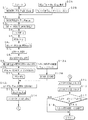
図1はその制御例を説明するためのフローチャートであって、先ず、出力側の従動プーリ14における推力WOUT が算出される(ステップS1)。具体的には、
WOUT =(Pd +Psch )*Aout
の式で算出される。すなわち、従動プーリ14側の油圧アクチュエータ16に作用している油圧Pd と、その油圧アクチュエータ16で生じている遠心油圧およびリターンスプリングなどによる弾性力の和Psch とを加えた圧力に、その油圧アクチュエータ16の受圧面積Aout を掛けて出力側の推力WOUT が算出される。この推力は、実際に作用している油圧に基づくものであるから、実推力と言い得るものである。
【0031】
一方、入力トルクに対応した従動プーリ14での推力(以下、仮に必要推力という)WOUTSLPが算出される(ステップS2)。すなわち滑りを生じることなく入力トルクを伝達できる最低の挟圧力を生じさせる推力であり、安全率SF が“1”の状態に相当する推力である。これは、例えば
WOUTSLP=Tt *cosα/(2*μ*Rin)
で算出される。ここで、Tt は入力トルク、αはプーリ13,14におけるベルト17の侠角、μはプーリ13,14とベルト17との間の摩擦係数、Rinは駆動プーリ13におけるベルト17の巻き掛け半径である。
【0032】
なお、入力トルクTt は、エンジン回転数Ne とエンジン負荷(例えばスロットル開度)とに基づいて推定トルクTe を求め(ステップS2A)、その推定トルクTe とイナーシャトルクとに基づいて求める(ステップS2B)ことができる。
【0033】
実推力WOUT は、無段変速機1に滑りが生じずに運転されている状態では必要推力WOUTSLPより高くなっているのが一般的であり、その超過分(あるいは余裕分)が安全率SF に相当している。そこで、その安全率SF が算出される(ステップS3)。具体的には、実推力WOUT と必要推力WOUTSLPとの比(WOUT /WOUTSLP)として安全率SF が算出される。
【0034】
こうして求められた安全率SF とその時点の変速比γとから推力比τが求められる(ステップS4)。具体的には、安全率SF と変速比γとによる予め用意したマップから推力比τが求められる。
【0035】
一方、駆動プーリ13における可動シーブの位置(軸線方向での位置)WDxが求められる(ステップS5)。変速比γはベルト17の各プーリ13,14に対する巻き掛け半径の比と等しいから、ステップS5においては変速比γによるマップに基づいて、前記可動シーブの位置WDxが求められる。
【0036】
図1にフローチャートで示すルーチンは、所定時間毎に繰り返し実行されており、したがって前記可動シーブの位置WDxも所定時間毎に求められている。そこでステップS6では、各ルーチン毎の位置変化量dx が求められる。これは、今回求められた前記可動シーブの位置WDx(i) と前回の値WDx(i−1) との差として求めることができる。
【0037】
ここで説明している具体例における前記ベルト17は、薄い金属片からなる多数のブロックを互いに密着させて環状に配列し、それらのブロックを金属製のフープ(それぞれ図示せず)によって結束した構造である。各プーリ13,14はそのブロックを挟み付けて円周方向に押して移動させることによりトルクを伝達する。駆動プーリ13に対して巻き掛かるそのブロックの数dN が算出される(ステップS7)。これは、変速比γと無段変速機1の入力回転数すなわち駆動プーリ13の回転数NINとによるマップに基づいて求められる。
【0038】
ついで、ブロック1個当たりの前記可動シーブの軸線方向移動量dx /dN が算出される(ステップS8)。無段変速機1における変速は、駆動プーリ13側の油圧アクチュエータ15に圧油を供給し、もしくは圧油を排出し、それに伴ってベルト17が引っ張られ、もしくは弛められ、その結果、従動プーリ14における固定シーブと可動シーブとの間隔(すなわち溝幅)が拡大もしくは縮小することにより生じる。このような変化は、いずれかのプーリ13,14における推力の変化によって生じるので、上記のステップS8で求められた軸線方向移動量dx /dN に基づいて駆動プーリ13での推力変化量VKVALDXが求められる(ステップS9)。具体的には、その推力変化量VKVALDXは、前記ブロック1個当たりの前記可動シーブの軸線方向移動量dx /dN によるマップに基づいて求められる。そのマップは、アップシフトとダウンシフトとでは別に設定される。
【0039】
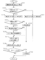
その推力変化量VKVALDXを利用して駆動プーリ13側の油圧アクチュエータ15の圧力Pinが算出される(ステップS10)。これは、
Pin=(VKVALDX+WOUT /τ−機械的推力分)/Ain
の式によって算出することができる。ここで、機械的推力分とは、遠心油圧に基づく推力やリータンスプリングなどの機械要素に基づく推力相当分などの総和であり、またAinは駆動プーリ13側の油圧アクチュエータ15における受圧面積である。なお、この式を変形すると、
Pin*Ain+機械的推力分−WOUT /τ=VKVALDX
となる。この式の左辺第1項と第2項とは、駆動プーリ13側の油圧アクチュエータ15で生じる推力WINであるから、上記の式は、
WIN−WOUT /τ=VKVALDX
に変形できる。
【0040】
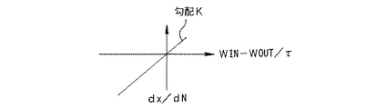
これが前述したブロック1個当たりの可動シーブの軸線方向移動量dx /dN に比例するとして
dx /dN =K*(WIN−WOUT /τ)
の式が成り立つ。この関係を図2に線図によって模式的に示してある。この比例定数Kは無段変速機1の運転状態で定まり、したがって運転状態をパラメータとしてマップとして予め定めておくことができる。なお、変速の生じない定常走行状態の場合には比例定数Kは“0”である。また、そのマップは、アップシフトとダウンシフトとでは別に設定される。
【0041】
また一方、駆動プーリ13側の油圧アクチュエータ15に供給される圧油の元圧であるライン圧PL が算出される(ステップS11)。挟圧力を設定する従動プーリ14側の油圧アクチュエータ16における油圧Pd が、ライン圧PL を元圧として設定されているので、これを利用することができ、したがって例えば
PL =Pd *A+B (A、Bは定数)
として算出することができる。
【0042】
こうして算出されたライン圧PL を使用して変速比制御弁流量qが算出される(ステップS12)。すなわち、変速比制御弁(図示せず)がデューティソレノイド弁によって構成されている場合、その入力側の圧力と出力側の圧力との差、およびデューティ比に基づいて流量が定まる。その入力側の圧力は、圧油を供給するアップシフトの場合はライン圧となり、また出力側の圧力は、駆動プーリ13側の油圧アクチュエータ15における油圧Pinとなる。したがってアップシフトの場合、その差圧(PL −Pin)と変速指令デューティ比DDS1 とからマップに基づいて流量qを求めることができる。これに対して圧油を排出するダウンシフトの場合には、入力側の圧力が油圧アクチュエータ15の圧力Pinとなり、出力側の圧力が大気圧すなわち“0”となるから、その差圧(PL −0)とダウンシフト指令デューティ比DDS2 とからマップに基づいて流量qを求めることができる。
【0043】
なお、変速比γは、入力回転数NINとその目標回転数NINT との差をフィードバック偏差としてフィードバック制御(ステップS12A)されるから、その変速の際のデューティ比DDS1 ,DDS2 を読み込んで(ステップS12B)、これをステップS12で利用すればはよい。
【0044】
変速比制御弁流量qは、要は、駆動プーリ13側の油圧アクチュエータ15に給排される圧油の量であるから、これを、その油圧アクチュエータ15におけるピストンの断面積(前記受圧面積Ain)でわり算することにより、駆動プーリ13での可動シーブの軸線方向移動量dx1が求められる(ステップS13)。駆動プーリ13での可動シーブが軸線方向に移動することにより、駆動プーリ13の溝幅すなわちベルト17の巻き掛け半径が変化して変速が生じるから、その可動シーブの軸線方向移動量dx1と変速比γとに基づいて理論変速比γ1 が求められる(ステップS14)。例えば、現時点の理論変速比γ1(i)と前記可動シーブの軸線方向移動量dx1とのマップから次の時点(1ルーチン先の時点)の理論変速比γ1(i+1)が求められる。
【0045】
こうして算出される理論変速比γ1 の単位時間当たりの変化量が理論変速比変化率Δγ1 である。これは、例えば図1に示すフローチャートの1ルーチンの時間Δtの間における理論変速比γ1 の変化量(γ1(i)−γ1(i−1))をその時間Δtでわり算({γ1(i)−γ1(i−1)}/Δt)することにより求められる。
【0046】
これと同様に、実変速比変化率Δγ(i) が算出される(ステップS16)。その実変速比γ(i) は、無段変速機1の入力回転速度NINと出力回転速度NOUT との比として算出される値であり、したがって実変速比変化率Δγ(i) は、その単位時間当たりの変化量である。すなわち
Δγ(i) ={γ(i) −γ(i−1) }/Δt
として算出することができる。
【0047】
したがって理論変速比変化率Δγ1 は、駆動プーリ13側の油圧アクチュエータ15に給排される圧油の量qに基づいて理論的に算出されたものであるから、ベルト17といずれかのプーリ13,14との間の滑りを含まない値である。これに対して実変速比変化率Δγは、各プーリ13,14の実際の回転速度に基づいて算出されたものであるから、無段変速機1に滑りが生じた場合には、その滑りに起因する変速比の変化を含んだものとなる。
【0048】
したがって理論変速比変化率Δγ1 と実変速比変化率Δγとを比較することにより、無段変速機1の滑りが検出される(ステップS17)。具体的には、実変速比変化率Δγと理論変速比変化率Δγ1 との差の絶対値が算出され、その絶対値が予め定めたしきい値Δγh 以上か否かが判断される。
【0049】
このステップS17で否定的に判断された場合には、実変速比変化率Δγが理論変速比変化率Δγ1 に近似していて無段変速機1に滑りが生じていないことになる。これとは反対にステップS17で肯定的に判断された場合には、実変速比変化率Δγが理論変速比変化率Δγ1 に対して大きく乖離しており、これは無段変速機1でのベルト17の滑りに起因していることが明らかであるから、ベルト滑りの判定が成立し、かつその滑り抑制もしくは収束のための対応処理が実行される(ステップS18)。なお、その対応処理は、例えば挟圧力を増大させる制御やエンジントルクを低下させる制御である。
【0050】
したがって上記の図1に示す制御を実行するように構成されたこの発明の装置では、変速を設定する駆動プーリ13での推力変化量と理論変速比変化率Δγ1 とが比例する関係を利用して理論変速比変化率Δγ1 を算出する。言い換えれば、推力変化量と理論変速比変化率Δγ1 とが比例する計算モデルに基づいて理論変速比変化率Δγ1 を算出するので、その算出を容易かつ迅速に、また精度良くおこなうことができる。したがってこの発明制御装置によれば、理論変速比変化率Δγ1 と実変速比変化率Δγとの比較結果に基づいて滑りを検出する場合に、その検出制御を容易かつ迅速に、また精度良くおこなうことができる。
【0051】
この発明に係る制御装置は、変速比制御弁の流量qを使用して理論変速比変化率Δγ1 を算出し、またその変速比制御弁流量qは、変速比制御弁に対するデューティ指令値に基づいて求めている。この変速比制御弁流量qとデューティ比との関係は、各変速比制御弁ごとに一定しているものの、個体差によって各変速比制御弁ごとにバラツキがある。そのために、上述した図1におけるステップS12で算出される流量と実際に流量とには誤差が生じることがある。前者の演算による流量は理論変速比変化率Δγ1 の算出に使用され、また後者の実際の流量は実変速比変化率Δγに反映される。したがって変速比制御弁流量の演算値と実際値との誤差は、理論変速比変化率Δγ1 と実変速比変化率Δγとの差あるいは理論変速比γ1 と実際の変速比γとの差として現れる。
【0052】
前述した滑り判定のためのしきい値Δγh を全ての変速比制御弁もしくは無段変速機1に対して同一とした場合には、上述した誤差をも含んで滑りを判断することになるので、滑り判定の精度が低下する可能性がある。そこで、この発明の制御装置では、滑り判定の精度を良好にするために、変速比制御弁の特性を考慮した制御をおこなうように構成されている。その一例を図3にフローチャートで示してある。
【0053】
図3において、先ず、弁特性に合わせた指令値の学習補正が終了しているか否かが判断される(ステップS21)。その弁特性とは、上述した図5に示す駆動プーリ13側の油圧アクチュエータ15に圧油を給排する変速比制御弁(図示せず)の特性であって、アップシフト用の変速比制御弁とダウンシフト用の変速比制御弁とのデューティ指令値と流量との関係である。また、その指令値の学習補正とは、変速比制御弁に対する所定のデューティ指令値で得られる流量を、変速比制御弁で実際に生じる流量に一致させるようにデューティ指令値を学習によって補正することである。
【0054】
前述したように、デューティ指令値から演算によって求められる流量が理論変速比γ1 として現れ、また実際の流量が実変速比γとして現れるので、これらの変速比γ1 ,γを比較することにより、変速比制御弁での流量の理論値と実際値との誤差を求めることができる。その誤差がゼロになるように、デューティ指令値を変更し、あるいはデューティ指令値についての補正係数を、実際に所定の変速比を設定することにより求めることにより、変速比制御弁の指令値についての学習をおこなうことができる。
【0055】
上記のステップS21ではこのような学習補正が完了しているか否かが判断され、肯定的に判断された場合には、滑り判定のためのしきい値Δγh (すなわち滑りの判断基準)として補正後の値が採用される(ステップS22)。これとは反対にステップS21で否定的に判断された場合には、変速比制御弁の指令値についての学習補正が完了する前の状態に対応させてある値が設定される(ステップS23)。
【0056】
これら変速比制御弁の指令値についての学習補正の有無に応じて設定されるしきい値Δγh は、予め定めた一定値であってよく、あるいは補正量に応じた変数であってもよい。また、変速比制御弁の指令値についての学習補正が完了する前に使用されるしきい値Δγh は、前記学習補正が完了した後に使用されるしきい値Δγh より大きい値に設定される。変速比制御弁の指令値についての学習補正が完了していない状態での滑り判定には、相対的に大きい誤差が含まれている可能性があり、これとは反対に前記学習補正が終了していれば、しきい値Δγh を小さくしても誤判定をおこなう可能性が少なく、精度の良い判定をおこない得るからである。
【0057】
こうして滑り判定のためのしきい値を設定した後に、理論変速比変化率Δγ1 が算出(ステップS24)されるとともに、実変速比変化率Δγが算出され(ステップS25)、さらにこれらの変化率Δγ1 ,Δγとの差の絶対値が、しきい値Δγh 以上か否かが判断される(ステップS26)。そして、このステップS26で否定的に判断された場合には、特に制御をおこなうことなく図3のルーチンを一旦終了し、これとは反対にステップS26で肯定的に判断された場合には、滑りの判定が成立するとともに、所定の対応処理が実行される(ステップS27)。このステップS24からステップS27までの各制御は、図1に示すステップS1からステップS18に示すとおりである。
【0058】
したがって図3に示す制御を実行するように構成した場合には、変速比制御弁の特性の個体差あるいは無段変速機1の個体差を、滑り判定に反映させることができるので、滑りの判定を容易かつ迅速におこなうことができることに加え、その判定精度を向上させることができる。
【0059】
図1を参照して説明したように、ベルト17を構成しているブロック1個当たりの可動シーブの軸線方向移動量を求め、その可動シーブの軸線方向移動量を使用して理論変速比γ1 やその変化率Δγ1 を算出し、かつ滑りの判定をおこなっている。そして、図1にフローチャートで示されるルーチンは、所定の短時間ごとに繰り返し実行される。したがって滑り判定のために実際に使用される理論変速比変化率Δγ1 や実変速比変化率Δγは、図1のルーチンを繰り返すごとに積算(積分)された値となる。すなわち、理論変速比変化率Δγ1 を求める演算は、積分操作を含んでいる。そのため、各積算処理ごとに僅かであっても誤差を含んでいると、その誤差も積算され、これが滑り判定の精度に影響を及ぼす。この発明の制御装置は、このような積分操作に伴う影響を可及的に抑制するために、以下のように制御をおこなう。
【0060】
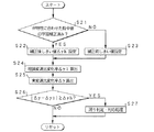
図4はその制御例を示すフローチャートであって、先ず、理論変速比変化率Δγ1 が算出される(ステップS31)。その算出の方法あるいは手順は図1を参集して説明したとおりである。次に、弁特性に合わせた指令値の学習補正が済んでいるか否かが判断される(ステップS32)。これは、前述した図3に示すステップS21と同様の判断である。このステップS32で肯定的に判断された場合には、滑り判定のためのしきい値Δγh として上記の学習補正が既に完了していることに対応した値が設定される(ステップS33)。これは、図3に示すステップS22と同様の制御である。
【0061】
必要挟圧力の検出条件が成立しているか否かが判断される(ステップS34)。ここで、必要挟圧力とは、エンジン5側からの入力トルクに釣り合ういわゆるトルク容量を設定する限界挟圧力に、路面入力対応分などの所定の安全を見込んだ圧力を加えた挟圧力である。この必要挟圧力を検出する場合、無段変速機1に作用する入力トルクなどのトルクが安定していることや制御が正常に実行されることなどの条件が必要であり、ステップS34ではその条件が成立しているか否かが判断される。具体的には、無段変速機1を搭載している車両の走行状態が定常状態もしくは準定常状態にあること、その時点の入力トルクに対する必要挟圧力が既に設定もしくは補正されていないことなどが必要挟圧力の検出条件であり、ステップS34ではこれが成立しているか否かが判断される。
【0062】
このステップS34で肯定的に判断された場合には、検出操作の開始前か否か、すなわち検出操作が既に開始されているか否かが判断される(ステップS35)。このステップS35で肯定的に判断された場合には、理論変速比変化率Δγ1 の算出の初期値が更新される(ステップS36)。すなわち車両が定常走行状態あるいは準定常走行状態などの安定した走行状態にあって、無段変速機1に作用するトルクが安定しており、理論変速比γ1 やその変化率Δγ1 などを算出する際に外乱となる要因が少なくなっているので、その状態での値(例えば入出力回転数から求められた変速比)を初期値として採用し、誤差を少なくするようにしたのである。
【0063】
その後、必要挟圧力の検出操作が実行される(ステップS37)。具体的には、挟圧力をオーバーシュートしないように徐々に低下させる。その過程で理論変速比γ1 やその変化率Δγ1 が逐次算出される。また同時に、実変速比変化率Δγが算出される(ステップS38)。なお、既に検出操作が開始されていてステップS35で否定的に判断された場合には、直ちにステップS37に進んで、必要挟圧力の検出制御を継続する。
【0064】
一方、必要挟圧力の検出条件が成立していないことによりステップS34で否定的に判断された場合には、挟圧力をその時点の入力トルクに対応した圧力もしくはライン圧(あるいはその補正圧)に設定するなどの対応処理Iを実行(ステップS39)した後、ステップS38に進む。また、弁特性に合わせた指令値の学習補正が完了していないことによりステップS32で否定的に判断された場合には、しきい値Δγh として補正前の値が設定され(ステップS40)、その後、ステップS38に進む。このステップS40の制御は、図3に示すステップS23と同様の制御である。
【0065】
ステップS31で理論変速比変化率Δγ1 が算出され、ステップS38で実変速比変化率Δγが算出されていることにより、これらの差の絶対値がしきい値Δγh 以上か否かが判断される(ステップS41)。このステップS41で否定的に判断された場合には、滑りが生じていないので、特に制御をおこなうことなくリターンする。これとは反対にステップS41で肯定的に判断された場合には、滑り判定の成立など、前述した図1のステップS18あるいは図3のステップS27と同様の対応処理IIが実行される(ステップS42)。
【0066】
したがって図4に示す制御を実行するように構成されたこの発明に係る制御装置によれば、必要挟圧力の検出制御の開始前で、その検出制御の開始条件が成立する定常状態あるいは準定常状態で、積分操作を含む理論変速比変化率Δγ1 の算出の初期値が更新されるので、理論変速比変化率Δγ1 についての誤差を抑制することができ、ひいては無段変速機1の滑りの判定およびそれに伴う必要挟圧力や限界挟圧力の検出を精度良くおこなうことができる。
【0067】
ここで上記の各具体例とこの発明との関係を簡単に説明すると、上述したステップS1からステップS15の機能的手段が、この発明の理論変速比変化率算出手段に相当し、ステップS21およびステップS32の機能的手段が、この発明の学習手段に相当し、さらにステップS22、ステップS23、ステップS33、ステップS40の各機能的手段が、この発明の滑り判断基準設定手段に相当する。さらに、ステップS34からステップS438およびステップS41の機能的手段が、この発明の滑り検出手段に相当し、ステップS36の機能的手段が、この発明の初期化手段に相当する。
【0068】
なお、この発明は上述した具体例に限定されないのであって、理論変速比変化率を求める手順あるいは演算式は、上述した具体例で述べたもの以外に適宜採用することができ、要は、推力変化量に比例する計算モデルに基づくものであればよい。また、変速比制御弁はいわゆるデューティ制御弁以外に、電流もしくは電圧に比例して動作するリニアーソレノイド弁であってもよい。
【0069】
【発明の効果】
以上説明したように、請求項1の発明によれば、変速比を設定するいずれか一方のプーリにおける推力の変化に理論変速比変化率が比例する計算モデルに基づいて、理論変速比変化率が求められ、その理論変速比変化率と、入力回転速度と出力回転速度とから求められる実変速比変化率とが比較されて、無段変速機での滑りが検出されるため、理論変速比変化率の算出が容易になり、無段変速機での滑りを迅速に、また精度良く検出することができる。
【0070】
また、請求項2の発明によれば、変速比制御弁の動作特性が学習され、その学習の前後で、前記滑り判断基準が変更されるため、変速比制御弁の動作特性を、理論変速比変化率と実変速比変化率との比較による滑りの判断に反映させることができ、その結果、変速比制御弁の動作特性に影響を受ける理論変速比変化率が滑りの判断に使用されているのに対して、その変速比制御弁の動作特性が滑り判断基準に反映させられるので、滑りの判断あるいは検出の精度を向上させることができる。
【0071】
さらに、請求項3の発明によれば、変速比制御弁の動作特性が学習された後、すなわち変速比制御弁の動作特性が制御データとして取り込むことが可能になっ後に、挟圧力を低下させるとともに、挟圧力の低下に伴う滑りを検出する制御を実行するため、変速比制御弁の動作特性を反映させることにより、変速比制御弁の動作特性が要因となる誤差を排除した状態での制御が可能になり、その結果、無段変速機での滑りの検出を迅速かつ精度良くおこなうことができる。
【0072】
そして、請求項4の発明によれば、理論変速比変化率の演算のための初期値が、トルクの安定している所定の状態で更新されるので、積分操作をおこなうとしても、誤差の累積などの誤差要因を抑制して、理論変速比変化率を使用した滑りの検出精度を向上させることができる。
【図面の簡単な説明】
【図1】この発明の制御装置による制御の一例を説明するためのフローチャートである。
【図2】推力変化量と可動シーブの軸線方向移動量との比例関係を模式的に示す線図である。
【図3】この発明の制御装置による他の制御例を説明するためのフローチャートである。
【図4】この発明の制御装置による更に他の制御例を説明するためのフローチャートである。
【図5】この発明で対象とする無段変速機を含む駆動機構の一例を模式的に示す図である。
【符号の説明】
1…無段変速機、 5…エンジン(動力源)、 13…駆動プーリ、 14…従動プーリ、 17…ベルト、 25…変速機用電子制御装置(CVT−ECU)、 26…エンジン用電子制御装置(E/G−ECU)。[0001]
TECHNICAL FIELD OF THE INVENTION
The present invention relates to a control device for a continuously variable transmission capable of continuously changing a gear ratio, and more particularly to a device for detecting slippage of a continuously variable transmission.
[0002]
[Prior art]
Belt-type continuously variable transmissions and traction-type continuously variable transmissions transmit torque using a frictional force between a belt and a pulley and a shearing force of traction oil between a disk and a roller. Therefore, when a torque exceeding the torque capacity acts, slippage occurs between the belt and the pulley or between the disk and the roller. If slippage occurs in the continuously variable transmission, it is necessary to perform an operation to eliminate the slippage, and to reduce the clamping force for setting the torque capacity as much as possible with respect to the input torque. When detecting the so-called limit clamping pressure at which slippage occurs, slippage may occur.
[0003]
As described above, slip detection in the continuously variable transmission must be always detected in controlling the continuously variable transmission. Since the slip in the continuously variable transmission appears as a change in the rotational speed of any member, the slip can be detected by a change in the gear ratio or the shift speed. That is, a value that is a so-called reference representing a state in which no slip occurs is determined, and the slip of the continuously variable transmission can be detected by comparing the value that is constantly detected with the so-called reference value.
[0004]
Conventionally, a theoretical gear ratio change rate is set as a so-called reference value, and the actual gear ratio change rate obtained based on the input rotational speed and the output rotational speed is compared with the theoretical gear ratio change rate.
[0005]
[Patent Document 1]
JP-A-6-11022 (paragraphs (0126) to (0131))
[Patent Document 2]
JP 2001-12593 A (Abstract,
[0006]
[Problems to be solved by the invention]
In the invention described in
[0007]
Therefore, conventionally, as described in
[0008]
The present invention has been made in view of the above technical problem, and has as its object to provide a control device that can easily and accurately detect slippage by using a theoretical gear ratio change rate. It is.
[0009]
Means for Solving the Problems and Their Functions
In order to achieve the above object, the invention of
[0010]
Therefore, in the first aspect of the present invention, the theoretical speed ratio change rate is determined based on a calculation model in which the theoretical speed ratio change rate is proportional to the change in the thrust in one of the pulleys that sets the speed ratio. Then, the actual speed ratio change rate obtained from the input rotation speed and the output rotation speed is compared with the above-described theoretical speed ratio change rate, and slippage in the continuously variable transmission is detected. Therefore, the calculation of the theoretical gear ratio change rate becomes easy, and slippage in the continuously variable transmission is quickly and accurately detected.
[0011]
According to a second aspect of the present invention, there is provided a control device for a continuously variable transmission which detects slip based on a comparison result between a theoretical speed ratio change rate and an actual speed ratio change rate obtained from an input rotation speed and an output rotation speed. Learning means for learning the operating characteristics of the speed ratio control valve for controlling the ratio, and a criterion for judging slippage based on a comparison result between the theoretical speed ratio change rate and the actual speed ratio change rate. And a slip determination criterion setting unit that changes before and after the control.
[0012]
Therefore, according to the second aspect of the present invention, the operating characteristics of the speed ratio control valve are learned, and before and after the learning, the slip determination criterion is changed. Therefore, the operating characteristics of the speed ratio control valve are reflected in the determination of slippage by comparing the theoretical speed ratio change rate and the actual speed ratio change rate. That is, while the theoretical gear ratio change rate, which is affected by the operating characteristics of the gear ratio control valve, is used for determining slip, the operating characteristics of the gear ratio control valve are reflected in the slip determination criterion. The accuracy of slip determination or detection is improved.
[0013]
Further, according to the third aspect of the invention, slip is detected by comparing the theoretical speed ratio change rate of the continuously variable transmission whose torque capacity changes due to the pinching force with the actual speed ratio change rate obtained from the input rotation speed and the output rotation speed. In the control device for a continuously variable transmission, learning means for learning the operating characteristics of the speed ratio control valve for controlling the speed ratio, and after the learning by the learning means is completed, the clamping pressure is reduced, and the clamping pressure is reduced. And a slip detecting means for detecting slip caused by the decrease.
[0014]
Therefore, according to the third aspect of the invention, after the operating characteristics of the speed ratio control valve are learned, that is, after the operating characteristics of the speed ratio control valve can be taken in as control data, the squeezing pressure is reduced and the squeezing pressure is reduced. Is executed to detect slippage due to the decrease in the vehicle speed. Therefore, by reflecting the operating characteristics of the speed ratio control valve, it is possible to perform control in a state in which an error caused by the operating characteristics of the speed ratio control valve is eliminated, and as a result, slippage in the continuously variable transmission is reduced. Detection is performed quickly and accurately.
[0015]
According to a fourth aspect of the present invention, there is provided a stepless continuously detecting slip based on a comparison result between a theoretical speed ratio change rate obtained by an operation including an integration operation and an actual speed ratio change rate obtained from an input rotation speed and an output rotation speed. The transmission control device includes an initialization unit that updates an initial value of the calculation of the theoretical gear ratio change rate in a predetermined state where the torque acting on the continuously variable transmission is stable. A control device characterized in that:
[0016]
Therefore, according to the fourth aspect of the present invention, the initial value for calculating the theoretical gear ratio change rate is updated in a predetermined state in which the torque is stable. Factors are suppressed, and as a result, slip detection accuracy using the theoretical speed ratio change rate is improved.
[0017]
BEST MODE FOR CARRYING OUT THE INVENTION
Next, the present invention will be described based on specific examples. First, an example of a drive system including a continuously variable transmission according to the present invention will be described. FIG. 5 schematically illustrates a drive mechanism including a belt-type continuously
[0018]
The power source 5 includes an internal combustion engine, an internal combustion engine and an electric motor, or an electric motor. In the following description, the power source 5 is referred to as an engine 5. The
[0019]
In the transmission of torque through such a fluid, inevitable slippage occurs between the pump impeller and the turbine runner, which causes a reduction in power transmission efficiency. And a lock-up clutch 3 for directly connecting to an output-side member such as The lock-up clutch 3 is configured to be controlled by hydraulic pressure, is controlled to a fully engaged state, a completely released state, and a slip state that is an intermediate state between these states, and can appropriately control the slip rotation speed. It has become.
[0020]
The forward /
[0021]
The continuously
[0022]
A hydraulic pressure (line pressure or its correction pressure) corresponding to the torque input to the continuously
[0023]
On the other hand, the
[0024]
The driven
[0025]
Various sensors are provided to detect the operation state (running state) of the vehicle equipped with the above-described continuously
[0026]
In order to control the engagement / disengagement of the
[0027]
Here, as an example of data (signal) input to the transmission
[0028]
According to the continuously
[0029]
In the above-described continuously
[0030]
FIG. 1 is a flowchart for explaining an example of the control. First, the thrust WOUT of the output driven
WOUT = (Pd + Psch) * Aout
Is calculated by the following equation. That is, the
[0031]
On the other hand, the thrust (hereinafter, tentatively required thrust) WOUTSLP at the driven
WOUTSLP = Tt * cosα / (2 * μ * Rin)
Is calculated. Here, Tt is an input torque, α is a skew angle of the
[0032]
The input torque Tt is determined based on the engine speed Ne and the engine load (eg, throttle opening) (step S2A), and is determined based on the estimated torque Te and the inertia torque (step S2B). be able to.
[0033]
The actual thrust WOUT is generally higher than the required thrust WOUTSLP in a state where the continuously
[0034]
The thrust ratio τ is obtained from the safety factor SF thus obtained and the gear ratio γ at that time (step S4). Specifically, the thrust ratio τ is obtained from a previously prepared map based on the safety factor SF and the gear ratio γ.
[0035]
On the other hand, the position (position in the axial direction) WDx of the movable sheave on the
[0036]
The routine shown in the flowchart of FIG. 1 is repeatedly executed at predetermined intervals, and therefore, the position WDx of the movable sheave is also determined at predetermined intervals. Therefore, in step S6, the position change amount dx for each routine is obtained. This can be obtained as the difference between the position WDx (i) of the movable sheave obtained this time and the previous value WDx (i-1).
[0037]
The
[0038]
Next, the axial movement amount dx / dN of the movable sheave per block is calculated (step S8). In the speed change in the continuously
[0039]
The pressure Pin of the
Pin = (VKVALDX + WOUT / τ-mechanical thrust) / Ain
Can be calculated by the following equation. Here, the mechanical thrust is a total sum of a thrust based on centrifugal hydraulic pressure and a thrust corresponding to a mechanical element such as a return spring, and Ain is a pressure receiving area of the
Pin * Ain + Mechanical thrust-WOUT / τ = VKVALDX
It becomes. The first and second terms on the left side of this equation are the thrust WIN generated by the
WIN−WOUT / τ = VKVALDX
Can be transformed into
[0040]
It is assumed that this is proportional to the above-described axial movement amount dx / dN of the movable sheave per block.
dx / dN = K * (WIN−WOUT / τ)
Holds. This relationship is schematically shown in FIG. 2 by a diagram. The proportionality constant K is determined depending on the operating state of the continuously
[0041]
On the other hand, the line pressure PL, which is the original pressure of the pressure oil supplied to the
PL = Pd * A + B (A and B are constants)
Can be calculated as
[0042]
The transmission ratio control valve flow rate q is calculated using the line pressure PL thus calculated (step S12). That is, when the speed ratio control valve (not shown) is constituted by a duty solenoid valve, the flow rate is determined based on the difference between the pressure on the input side and the pressure on the output side and the duty ratio. The pressure on the input side becomes the line pressure in the case of an upshift for supplying the pressure oil, and the pressure on the output side becomes the hydraulic pressure Pin in the
[0043]
Since the gear ratio γ is subjected to feedback control (step S12A) using the difference between the input rotational speed NIN and its target rotational speed NINT as a feedback deviation, the duty ratios DDS1 and DDS2 for the gear change are read (step S12B). ), This may be used in step S12.
[0044]
Since the gear ratio control valve flow rate q is essentially the amount of pressure oil supplied to and discharged from the
[0045]
The amount of change in the theoretical speed ratio γ1 thus calculated per unit time is the theoretical speed ratio change rate Δγ1. For example, the change amount (γ1 (i) −γ1 (i−1)) of the theoretical speed ratio γ1 during the time Δt of one routine of the flowchart shown in FIG. 1 is divided by the time Δt ({γ1 (i)). −γ1 (i−1)} / Δt).
[0046]
Similarly, the actual speed ratio change rate Δγ (i) is calculated (step S16). The actual speed ratio γ (i) is a value calculated as a ratio between the input rotation speed NIN and the output rotation speed NOUT of the continuously
Δγ (i) = {γ (i) −γ (i−1)} / Δt
Can be calculated as
[0047]
Therefore, the theoretical speed ratio change rate Δγ1 is theoretically calculated based on the amount q of the pressure oil supplied / discharged to / from the
[0048]
Therefore, the slip of the continuously
[0049]
If a negative determination is made in step S17, it means that the actual speed ratio change rate Δγ is close to the theoretical speed ratio change rate Δγ1, and no slippage has occurred in the continuously
[0050]
Therefore, in the device of the present invention configured to execute the control shown in FIG. 1 described above, utilizing the relationship in which the thrust change amount at the
[0051]
The control device according to the present invention calculates the theoretical speed ratio change rate Δγ1 using the flow rate q of the speed ratio control valve, and the speed ratio control valve flow rate q is based on a duty command value for the speed ratio control valve. I'm asking. Although the relationship between the flow rate control valve flow rate q and the duty ratio is constant for each speed ratio control valve, there is variation among the speed ratio control valves due to individual differences. Therefore, an error may occur between the flow rate calculated in step S12 in FIG. 1 described above and the actual flow rate. The flow rate obtained by the former calculation is used to calculate the theoretical speed ratio change rate Δγ1, and the actual flow rate of the latter is reflected in the actual speed ratio change rate Δγ. Therefore, an error between the calculated value of the speed ratio control valve flow rate and the actual value appears as a difference between the theoretical speed ratio change rate Δγ1 and the actual speed ratio change rate Δγ or a difference between the theoretical speed ratio γ1 and the actual speed ratio γ.
[0052]
If the threshold value Δγh for the slip determination described above is the same for all the speed ratio control valves or the continuously
[0053]
In FIG. 3, first, it is determined whether learning correction of a command value according to valve characteristics has been completed (step S21). The valve characteristics are characteristics of a speed ratio control valve (not shown) for supplying and discharging pressure oil to and from the
[0054]
As described above, the flow rate obtained by calculation from the duty command value appears as the theoretical gear ratio γ1, and the actual flow rate appears as the actual gear ratio γ. By comparing these gear ratios γ1, γ, the gear ratio is calculated. An error between the theoretical value and the actual value of the flow rate at the control valve can be obtained. The duty command value is changed so that the error becomes zero, or a correction coefficient for the duty command value is obtained by actually setting a predetermined gear ratio, thereby obtaining a command value for the gear ratio control valve. Can learn.
[0055]
In the above step S21, it is determined whether or not such learning correction has been completed. If the determination is affirmative, the threshold value Δγh for slip determination (that is, the slip determination criterion) is used. Is adopted (step S22). Conversely, if the determination in step S21 is negative, a value corresponding to the state before the learning correction of the command value of the speed ratio control valve is completed is set (step S23).
[0056]
The threshold value Δγh set in accordance with the presence or absence of the learning correction for the command value of the speed ratio control valve may be a predetermined constant value or may be a variable corresponding to the correction amount. The threshold value Δγh used before the learning correction for the command value of the gear ratio control valve is completed is set to a value larger than the threshold value Δγh used after the learning correction is completed. The slip determination in a state where the learning correction for the command value of the speed ratio control valve has not been completed may include a relatively large error, and conversely, the learning correction is terminated. In this case, the possibility of making an erroneous determination is small even if the threshold value Δγh is reduced, and accurate determination can be made.
[0057]
After setting the threshold value for slip determination in this way, the theoretical gear ratio change rate Δγ1 is calculated (step S24), the actual gear ratio change rate Δγ is calculated (step S25), and these change rates Δγ1 are further calculated. , Δγ are determined to be greater than or equal to a threshold value Δγh (step S26). If a negative determination is made in step S26, the routine of FIG. 3 is terminated once without performing any particular control. Conversely, if a positive determination is made in step S26, the slippage is stopped. Is established, and a predetermined corresponding process is executed (step S27). Each control from step S24 to step S27 is as shown from step S1 to step S18 shown in FIG.
[0058]
Accordingly, when the control shown in FIG. 3 is configured to execute, the individual difference in the characteristics of the speed ratio control valve or the individual difference of the continuously
[0059]
As described with reference to FIG. 1, the axial movement amount of the movable sheave per block constituting the
[0060]
FIG. 4 is a flowchart showing an example of the control. First, the theoretical speed ratio change rate Δγ1 is calculated (step S31). The calculation method or procedure is as described with reference to FIG. Next, it is determined whether learning correction of the command value according to the valve characteristics has been completed (step S32). This is the same determination as in step S21 shown in FIG. If an affirmative determination is made in step S32, a value corresponding to the completion of the learning correction has been set as the threshold Δγh for slip determination (step S33). This is the same control as in step S22 shown in FIG.
[0061]
It is determined whether the condition for detecting the necessary clamping pressure is satisfied (step S34). Here, the required squeezing pressure is a squeezing pressure obtained by adding a pressure that allows for a predetermined safety such as a portion corresponding to a road surface input to a limit squeezing pressure for setting a so-called torque capacity that is balanced with the input torque from the engine 5 side. In order to detect the required pinching pressure, conditions such as a stable torque such as an input torque acting on the continuously
[0062]
If the determination in step S34 is affirmative, it is determined whether or not the detection operation has been started, that is, whether or not the detection operation has already been started (step S35). If the determination in step S35 is affirmative, the initial value of the calculation of the theoretical speed ratio change rate Δγ1 is updated (step S36). That is, when the vehicle is in a stable running state such as a steady running state or a quasi-steady running state, the torque acting on the continuously
[0063]
Thereafter, the operation of detecting the required clamping pressure is executed (step S37). Specifically, the clamping pressure is gradually reduced so as not to overshoot. In the process, the theoretical speed ratio γ1 and its change rate Δγ1 are sequentially calculated. At the same time, the actual speed ratio change rate Δγ is calculated (step S38). If the detection operation has already been started and a negative determination is made in step S35, the process immediately proceeds to step S37 to continue the detection control of the necessary clamping pressure.
[0064]
On the other hand, if a negative determination is made in step S34 because the detection condition of the necessary clamping pressure is not satisfied, the clamping pressure is changed to the pressure or the line pressure (or its correction pressure) corresponding to the input torque at that time. After executing the corresponding process I such as setting (step S39), the process proceeds to step S38. If a negative determination is made in step S32 because the learning correction of the command value in accordance with the valve characteristics has not been completed, the value before correction is set as the threshold value Δγh (step S40), and thereafter The process proceeds to step S38. The control in step S40 is similar to the control in step S23 shown in FIG.
[0065]
Since the theoretical speed ratio change rate Δγ1 is calculated in step S31 and the actual speed ratio change rate Δγ is calculated in step S38, it is determined whether or not the absolute value of these differences is equal to or larger than the threshold value Δγh ( Step S41). If a negative determination is made in step S41, since no slippage has occurred, the routine returns without performing any particular control. Conversely, if the determination is affirmative in step S41, the corresponding processing II similar to step S18 in FIG. 1 or step S27 in FIG. 3 described above, such as the establishment of a slip determination, is executed (step S42). ).
[0066]
Therefore, according to the control device according to the present invention configured to execute the control shown in FIG. 4, before the start of the detection control of the necessary clamping pressure, the steady state or the quasi-stationary state in which the start condition of the detection control is satisfied Then, the initial value of the calculation of the theoretical speed ratio change rate Δγ1 including the integration operation is updated, so that the error with respect to the theoretical speed ratio change rate Δγ1 can be suppressed. Accordingly, it is possible to accurately detect the required clamping pressure and the limit clamping pressure.
[0067]
Here, the relationship between each of the above specific examples and the present invention will be briefly described. The functional means of the above-described steps S1 to S15 correspond to the theoretical gear ratio change rate calculating means of the present invention, The functional means of S32 corresponds to the learning means of the present invention, and the functional means of steps S22, S23, S33, and S40 correspond to the slip determination criterion setting means of the present invention. Further, the functional means of steps S34 to S438 and S41 correspond to the slip detecting means of the present invention, and the functional means of step S36 corresponds to the initializing means of the present invention.
[0068]
It should be noted that the present invention is not limited to the specific example described above, and the procedure or arithmetic expression for calculating the theoretical speed change ratio can be appropriately adopted other than that described in the above specific example. What is necessary is just to be based on the calculation model proportional to the amount of change. The speed ratio control valve may be a linear solenoid valve that operates in proportion to current or voltage, other than the so-called duty control valve.
[0069]
【The invention's effect】
As described above, according to the first aspect of the invention, the theoretical gear ratio change rate is calculated based on the calculation model in which the theoretical gear ratio change rate is proportional to the change in thrust in one of the pulleys for setting the gear ratio. The slip ratio of the continuously variable transmission is detected by comparing the theoretical speed ratio change rate and the actual speed ratio change rate obtained from the input rotation speed and the output rotation speed. The ratio can be easily calculated, and slippage in the continuously variable transmission can be quickly and accurately detected.
[0070]
According to the second aspect of the present invention, the operating characteristics of the speed ratio control valve are learned, and before and after the learning, the slip determination criterion is changed. The change rate and the actual gear ratio change rate can be reflected in the determination of slip, and as a result, the theoretical gear ratio change rate, which is affected by the operation characteristics of the gear ratio control valve, is used for slip determination. On the other hand, since the operating characteristics of the speed ratio control valve are reflected in the slip determination criteria, the accuracy of slip determination or detection can be improved.
[0071]
Further, according to the invention of claim 3, after the operating characteristics of the speed ratio control valve are learned, that is, after the operating characteristics of the speed ratio control valve can be taken in as control data, the clamping pressure is reduced and In order to execute control to detect slippage due to a decrease in clamping pressure, by reflecting the operation characteristics of the speed ratio control valve, control in a state in which an error caused by the operation characteristics of the speed ratio control valve is eliminated is performed. As a result, it is possible to quickly and accurately detect slippage in the continuously variable transmission.
[0072]
According to the fourth aspect of the present invention, the initial value for calculating the rate of change of the theoretical gear ratio is updated in a predetermined state where the torque is stable. Error factors such as the above can be suppressed, and the accuracy of slip detection using the theoretical gear ratio change rate can be improved.
[Brief description of the drawings]
FIG. 1 is a flowchart illustrating an example of control by a control device according to the present invention.
FIG. 2 is a diagram schematically illustrating a proportional relationship between a thrust change amount and an axial movement amount of a movable sheave.
FIG. 3 is a flowchart for explaining another control example by the control device of the present invention.
FIG. 4 is a flowchart for explaining still another control example by the control device of the present invention.
FIG. 5 is a diagram schematically illustrating an example of a drive mechanism including a continuously variable transmission targeted by the present invention.
[Explanation of symbols]
DESCRIPTION OF
Claims (4)
理論変速比変化率が前記推力の変化量に比例する計算モデルに基づいて前記理論変速比変化率を算出する理論変速比変化率算出手段を備えていることを特徴とする無段変速機の制御装置。A belt wound around a driving pulley and a driven pulley is pinched by applying an axial thrust to each pulley, and the slip of any of the belts on one of the pulleys is calculated based on a theoretical speed ratio change rate, an input rotation speed, and an output rotation speed. In the control device of the continuously variable transmission that detects based on the actual speed ratio change rate obtained from
Control of a continuously variable transmission, comprising: theoretical speed ratio change rate calculating means for calculating the theoretical speed ratio change rate based on a calculation model in which the theoretical speed ratio change rate is proportional to the thrust change amount. apparatus.
変速比を制御する変速比制御弁の動作特性を学習する学習手段と、
前記理論変速比変化率と実変速比変化率との比較結果に基づいて滑りを判断する判断基準を、前記学習手段による学習の前後で変更する滑り判断基準設定手段と
を備えていることを特徴とする無段変速機の制御装置。In the control device of the continuously variable transmission that detects slip based on a comparison result between the theoretical speed ratio change rate and the actual speed ratio change rate obtained from the input rotation speed and the output rotation speed,
Learning means for learning operating characteristics of a speed ratio control valve for controlling a speed ratio;
And a slip criterion setting means for changing a criterion for judging slippage based on a comparison result between the theoretical gear ratio change rate and the actual gear ratio change rate before and after learning by the learning means. Control device for a continuously variable transmission.
変速比を制御する変速比制御弁の動作特性を学習する学習手段と、
その学習手段による学習が終了した後に、前記挟圧力を低下させ、かつ挟圧力の低下に伴う滑りを検出する滑り検出手段と
を備えていることを特徴とする無段変速機の制御装置。A control device for a continuously variable transmission that detects slippage by comparing the theoretical gear ratio change rate of a continuously variable transmission whose torque capacity changes due to pinching pressure with the actual gear ratio change rate obtained from an input rotation speed and an output rotation speed. ,
Learning means for learning operating characteristics of a speed ratio control valve for controlling a speed ratio;
A control device for a continuously variable transmission, comprising: a slip detecting means for reducing the clamping force after the learning by the learning means is completed and detecting a slip caused by the decrease in the clamping force.
前記無段変速機に作用するトルクが安定している予め定めた所定の状態で、前記理論変速比変化率の演算の初期値を更新する初期化手段を備えていることを特徴とする無段変速機の制御装置。A control device for a continuously variable transmission that detects slip based on a comparison result between a theoretical speed ratio change rate obtained by an operation including an integration operation and an actual speed ratio change rate obtained from an input rotation speed and an output rotation speed,
And a step of updating the initial value of the calculation of the rate of change of the theoretical transmission ratio in a predetermined state in which the torque acting on the continuously variable transmission is stable. Transmission control device.
Priority Applications (1)
| Application Number | Priority Date | Filing Date | Title |
|---|---|---|---|
| JP2003132222A JP2004332878A (en) | 2003-05-09 | 2003-05-09 | Control device of continuously variable transmission |
Applications Claiming Priority (1)
| Application Number | Priority Date | Filing Date | Title |
|---|---|---|---|
| JP2003132222A JP2004332878A (en) | 2003-05-09 | 2003-05-09 | Control device of continuously variable transmission |
Publications (1)
| Publication Number | Publication Date |
|---|---|
| JP2004332878A true JP2004332878A (en) | 2004-11-25 |
Family
ID=33507168
Family Applications (1)
| Application Number | Title | Priority Date | Filing Date |
|---|---|---|---|
| JP2003132222A Pending JP2004332878A (en) | 2003-05-09 | 2003-05-09 | Control device of continuously variable transmission |
Country Status (1)
| Country | Link |
|---|---|
| JP (1) | JP2004332878A (en) |
Cited By (4)
| Publication number | Priority date | Publication date | Assignee | Title |
|---|---|---|---|---|
| JP2010180995A (en) * | 2009-02-07 | 2010-08-19 | Nissan Motor Co Ltd | Belt slip state determination device of v-belt type continuously variable transmission |
| KR20110021684A (en) * | 2009-08-26 | 2011-03-04 | 쟈트코 가부시키가이샤 | Continuously variable transmission and control method for the same |
| KR20180066756A (en) * | 2016-12-09 | 2018-06-19 | 현대오트론 주식회사 | Kick down Gear ratio studying device and method of Continuously Variable Transmission vehicle |
| KR20210149278A (en) * | 2020-06-01 | 2021-12-09 | 주식회사 현대케피코 | Pulley controlling hydraulic pressure calibration method and device of CVT |
-
2003
- 2003-05-09 JP JP2003132222A patent/JP2004332878A/en active Pending
Cited By (9)
| Publication number | Priority date | Publication date | Assignee | Title |
|---|---|---|---|---|
| JP2010180995A (en) * | 2009-02-07 | 2010-08-19 | Nissan Motor Co Ltd | Belt slip state determination device of v-belt type continuously variable transmission |
| KR20110021684A (en) * | 2009-08-26 | 2011-03-04 | 쟈트코 가부시키가이샤 | Continuously variable transmission and control method for the same |
| JP2011047459A (en) * | 2009-08-26 | 2011-03-10 | Jatco Ltd | Continuously variable transmission and method for controlling the same |
| US8414453B2 (en) | 2009-08-26 | 2013-04-09 | Jatco Ltd | Continuously variable transmission and control method thereof |
| KR101691664B1 (en) | 2009-08-26 | 2016-12-30 | 쟈트코 가부시키가이샤 | Continuously variable transmission and control method for the same |
| KR20180066756A (en) * | 2016-12-09 | 2018-06-19 | 현대오트론 주식회사 | Kick down Gear ratio studying device and method of Continuously Variable Transmission vehicle |
| KR101917376B1 (en) | 2016-12-09 | 2018-11-09 | 현대오트론 주식회사 | Kick down Gear ratio studying device and method of Continuously Variable Transmission vehicle |
| KR20210149278A (en) * | 2020-06-01 | 2021-12-09 | 주식회사 현대케피코 | Pulley controlling hydraulic pressure calibration method and device of CVT |
| KR102371746B1 (en) * | 2020-06-01 | 2022-03-08 | 주식회사 현대케피코 | Pulley controlling hydraulic pressure calibration method and device of CVT |
Similar Documents
| Publication | Publication Date | Title |
|---|---|---|
| JP4687096B2 (en) | Control device for belt type continuously variable transmission | |
| JP2004092669A (en) | Belt type continuously variable transmission | |
| JP4126152B2 (en) | Shift control device for continuously variable transmission | |
| JP4395137B2 (en) | Vehicle torque control device | |
| CN110118249B (en) | Control device for vehicle power transmission device | |
| JP2003120804A (en) | Controller for driving mechanism including continuously variable transmission | |
| JP4072200B2 (en) | Control device for belt type continuously variable transmission | |
| JP2004332878A (en) | Control device of continuously variable transmission | |
| JP4106992B2 (en) | Rotational speed estimation device | |
| JP2004316860A (en) | Controller of stepless speed change gear | |
| JP2004100920A (en) | Control device for continuously variable transmission | |
| JP7040011B2 (en) | Control device for vehicle power transmission device | |
| JP4396203B2 (en) | Control device for continuously variable transmission | |
| JP4474832B2 (en) | Control device for continuously variable transmission | |
| JP4158665B2 (en) | Control device for power transmission mechanism | |
| JP2004293654A (en) | Control device for power transmission mechanism | |
| JP4380170B2 (en) | Control device for continuously variable transmission | |
| JP6907949B2 (en) | Control device for continuously variable transmission | |
| JP7273709B2 (en) | VEHICLE CONTROL DEVICE AND VEHICLE CONTROL METHOD | |
| JP2004332851A (en) | Control device for continuously variable transmission | |
| JP2004316861A (en) | Controller for continuously variable transmission | |
| JP4349099B2 (en) | Control device for continuously variable transmission | |
| JP2004301230A (en) | Slip detecting device for continuously variable transmission | |
| JP2004293653A (en) | Clutch control device | |
| JP2004360848A (en) | Speed change control device of continuously variable transmission |