JP2004310103A - Reflective illuminating optical system - Google Patents
Reflective illuminating optical system Download PDFInfo
- Publication number
- JP2004310103A JP2004310103A JP2004111278A JP2004111278A JP2004310103A JP 2004310103 A JP2004310103 A JP 2004310103A JP 2004111278 A JP2004111278 A JP 2004111278A JP 2004111278 A JP2004111278 A JP 2004111278A JP 2004310103 A JP2004310103 A JP 2004310103A
- Authority
- JP
- Japan
- Prior art keywords
- light
- pbs
- type
- flat
- reflected
- Prior art date
- Legal status (The legal status is an assumption and is not a legal conclusion. Google has not performed a legal analysis and makes no representation as to the accuracy of the status listed.)
- Pending
Links
Images


Classifications
-
- H—ELECTRICITY
- H04—ELECTRIC COMMUNICATION TECHNIQUE
- H04N—PICTORIAL COMMUNICATION, e.g. TELEVISION
- H04N5/00—Details of television systems
- H04N5/74—Projection arrangements for image reproduction, e.g. using eidophor
-
- H—ELECTRICITY
- H04—ELECTRIC COMMUNICATION TECHNIQUE
- H04N—PICTORIAL COMMUNICATION, e.g. TELEVISION
- H04N9/00—Details of colour television systems
- H04N9/12—Picture reproducers
- H04N9/31—Projection devices for colour picture display, e.g. using electronic spatial light modulators [ESLM]
- H04N9/3102—Projection devices for colour picture display, e.g. using electronic spatial light modulators [ESLM] using two-dimensional electronic spatial light modulators
- H04N9/3105—Projection devices for colour picture display, e.g. using electronic spatial light modulators [ESLM] using two-dimensional electronic spatial light modulators for displaying all colours simultaneously, e.g. by using two or more electronic spatial light modulators
Landscapes
- Engineering & Computer Science (AREA)
- Multimedia (AREA)
- Signal Processing (AREA)
- Projection Apparatus (AREA)
- Liquid Crystal (AREA)
Abstract
Description
本発明は反射型照明光学系に係り、特に赤色光R、緑色光G、及び青色光Bの各信号がフィルムタイプの平板型PBS(Wire Grid Type Polarized Beam Splitter)に反射され、投射レンズに入射されるようにすることによって、非点収差の発生を抑制して照明効率を高めた反射型照明光学系に関する。 The present invention relates to a reflection-type illumination optical system, and in particular, signals of red light R, green light G, and blue light B are reflected by a film-type flat PBS (Wire Grid Type Polarized Beam Splitter) and incident on a projection lens. The present invention relates to a reflection-type illumination optical system in which the generation of astigmatism is suppressed to improve the illumination efficiency.
最近ディスプレィ装置は軽量化、薄型化、および大画面化になっている。特に、大画面ディスプレィ装置は、ディスプレィの分野において重要な課題になっている。このような大画面ディスプレィ装置の代表的な例として、プロジェクション・テレビがある。 Recently, display devices have become lighter, thinner, and larger in size. In particular, large-screen display devices have become an important issue in the field of displays. A typical example of such a large-screen display device is a projection television.
プロジェクション・テレビは、CRTプロジェクション・テレビと、LCDプロジェクション・テレビの2種の形態に分けることができるが、LCDを利用したプロジェクション・テレビは、さらに、透過型LCDを利用するシステムと、反射型LCD(Liquid Crystal on Silicon;LCoS)を利用するシステムに分けられる。
反射型LCDを利用するシステムは、透過型LCDよりパネルの価格を低廉に製作できる長所がある。
Projection televisions can be divided into two types, CRT projection televisions and LCD projection televisions. Projection televisions using LCDs are further divided into systems using transmissive LCDs and reflective LCDs. (Liquid Crystal on Silicon; LCoS).
A system using a reflective LCD has an advantage that a panel can be manufactured at a lower price than a transmissive LCD.
以下、添付した図面を参照しながら従来のプロジェクションシステム及び照明系に関して説明すると、次の通りである。
図1ないし図4は、従来の3板式反射型LCD照明系の構成図である。
従来の反射型LCDを利用したプロジェクション・テレビの照明系の一つで、図1の3PBS( Polarized Beam Splitter偏光ビームスプリッタ)システムの反射型照明系は、ランプ1から照射された光が、集光レンズを経て第1ダイクロイックミラー2を透過するが、そこでは、赤色光R、緑色光Gの光は反射され、青色光Bは透過する。
Hereinafter, a conventional projection system and illumination system will be described with reference to the accompanying drawings.
1 to 4 are configuration diagrams of a conventional three-panel reflective LCD illumination system.
One of the illumination systems of a projection television using a conventional reflective LCD, the reflective illumination system of the 3PBS (Polarized Beam Splitter) system shown in FIG. The light passes through the first dichroic mirror 2 via the lens, where the red light R and the green light G are reflected, and the blue light B is transmitted.
そして、反射した赤色光(R)、緑色光(G)は、第2ダイクロイックミラー3を透過し、その時、緑色光は反射されて、赤色光は透過し、その後、R、G、BLCoSパネル5a、5b、5cの前にある、第1、第2、第3のPBS4a、4b、4cに入射する。
Then, the reflected red light (R) and green light (G) pass through the second dichroic mirror 3, at which time the green light is reflected and the red light is transmitted, and thereafter, the R, G,
第1、第2、第3のPBS4a、4b、4cに入射した赤色光、緑色光、及び青色光は、反射して第1、第2、第3のLCoSパネル5a、5b、5cに入射し、入射したそれぞれの赤色光、緑色光、及び青色光は、第1、第2、第3のLCoSパネル5a、5b、5cにより位相が変えられて反射され、それぞれ第1、第2、第3のPBS4a、4b、4cを透過する。
The red light, green light, and blue light incident on the first, second, and
透過した赤色光、緑色光、及び青色光は、X−プリズム6で合成されて、投射レンズに入射する。
このような構造の3PBSシステムの反射型照明系では、ランプ1及び第1ダイクロイックミラー2による1段と、第2ダイクロイックミラー3と第2LCoSパネル5b及び第2PBS4bによる2段、そして第1、第3のLCoSパネル5a、5c、X−プリズム6、第1及び第3のPBS4a、4cによる3段の構成からなるために、システム(装置)の奥行き(Depth)が大きくなる。
The transmitted red light, green light, and blue light are combined by the X-prism 6 and enter the projection lens.
In the reflection type illumination system of the 3PBS system having such a structure, one stage by the lamp 1 and the first dichroic mirror 2, two stages by the second dichroic mirror 3, the
また、システムを構成する部品の個数がダイクロイックミラー2枚、ミラー1枚そして赤色光、緑色光、青色光の経路差を補正するための、リレーレンズ、PBS3個、X−プリズムなどの多くの部品を必要とする。 In addition, the number of components constituting the system includes two dichroic mirrors, one mirror, and many components such as a relay lens, three PBSs, and an X-prism for correcting a path difference between red light, green light, and blue light. Need.
図2に示される、カラークオード(Color Quad)システムの従来の3板式反射型LCD照明系の例では、リレーシステムの代りにカラーセレクター(color selector)を用いている。
図2の照明系は、カラーセレクターを用いて赤色光、緑色光、及び青色光の光経路の差をなくしたものであって、ランプ7から出た光が、第1カラーセレクター8aを透過しながら青色光BだけS波(Secondary wave)に変わって、赤色光R、緑色光GはP波(Primary wave)で出力される。
In the example of the conventional three-plate reflective LCD illumination system of the Color Quad system shown in FIG. 2, a color selector is used instead of the relay system.
The illumination system shown in FIG. 2 uses a color selector to eliminate the difference between the light paths of red light, green light, and blue light. Light emitted from the lamp 7 passes through the first color selector 8a. However, only blue light B is changed to S wave (Secondary wave), and red light R and green light G are output as P wave (Primary wave).
この光が第1PBS9aにより、S波は反射されてP波は透過し、青色光BはLCoSパネルの前にある第2PBS9bに到達する。
この青色光は、再び第2PBS9bで反射されて第3LCoSパネル10cに入射し、反射されながら位相が変わって第2PBS9bを透過し、第4カラーセレクター8dを経て第4PBS9dに入射する。
そして赤色光、緑色光は、第2カラーセレクター8bにより緑色光はS波で、赤色光はP波で第3PBS9cに入射する。第3PBS9cで緑色光は反射して赤色光は透過し、それぞれ第1、2LCoSパネル10a、10bに入射する。
The light is reflected by the
The blue light is reflected again by the second PBS 9b and enters the
The red light and the green light are incident on the
第1、2LCoSパネル10a、10bに入射された緑色光、赤色光は、位相が変わって反射され、再び第3PBS9cに入射して合成され、第3カラーセレクター8cによって偏光状態が等しくなり、第4PBS9dに入射する。
The green light and the red light incident on the first and
このような過程で第4PBS9dに到達した赤色光R、緑色光G、及び青色光Bは、PBSのP/S分離及び合成の特性により合成されて投射レンズに入射される。
このようなカラークオードシステムの3板式反射型LCD照明系は2段構成で形成されており、リレーシステムが要らなくて構成が単純化はされたが、4個のカラーセレクターとPBSを含むために価格面で有利でない。
The red light R, the green light G, and the blue light B that have reached the
The three-plate reflective LCD illumination system of such a color quad system is formed in a two-stage configuration, and the configuration is simplified without the need for a relay system. However, since the configuration includes four color selectors and a PBS, the configuration is simplified. It is not advantageous in terms of price.
そしてPBSでP/S分離及び合成をする過程で、入力された波が出力される時、他の成分の偏光を有するようになる光弾性問題がありうる。
以上、説明した従来技術の光学系の価格面での問題、PBSによる光弾性問題を解決して、広角の照明光を用いて照明効率を高めるために、図5に示す平板型PBS(Wire Grid Type PBS)を用いる照明系が提示された。
In the process of P / S separation and combining in the PBS, when an input wave is output, there may be a photoelastic problem that the component has polarization of another component.
As described above, in order to solve the problem of the price of the conventional optical system and the photoelasticity problem of the PBS, and to improve the illumination efficiency by using the wide-angle illumination light, a flat-type PBS (Wire Grid) shown in FIG. An illumination system using Type PBS) was presented.
図3の構造を有する平板型PBSを用いる照明系は、ランプ11から照射された光が集光レンズを経て第1ダイクロイックミラー12aにより、赤色光R、緑色光Gの光は透過し、青色光Bの光は反射される。
そして透過した赤色光、緑色光は、カラーセレクター14を透過して、緑色光はS波で、赤色光はP波で、第2平板型PBS13bに入射する。第2平板型PBS13bで赤色光は透過し、緑色光は反射して、それぞれ第1、第2のLCoSパネル15a、15bに入射する。
In the illumination system using the flat-type PBS having the structure shown in FIG. 3, the light emitted from the
The transmitted red light and green light pass through the
第1、第2のLCoSパネル15a、15bに入射した緑色光、赤色光は、位相が変わって反射され、再び第2平板型PBS13bを経て第2ダイクロイックミラー12bを透過し、投射レンズに入射する。
そして青色光は、第1ダイクロイックミラー12aで反射され、第1平板型PBS13aに反射して第3LCoSパネル15cに入射し、位相が変わって反射されて再び第1平板型PBS13aを経て、第2ダイクロイックミラー12bにより反射して投射レンズに入射する。
The green light and red light incident on the first and
Then, the blue light is reflected by the first
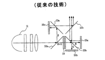
図4の構造を有する平板型PBSを用いる照明系は、ランプ16から照射された光は、集光レンズを経て第1ダイクロイックミラー17により赤色光R、緑色光Gは反射し、青色光Bは透過する。
透過した青色光は、第2リレーレンズ18b、反射ミラー、第3リレーレンズ18cを経て、第3平板型PBS20cにより反射して第3LCoSパネル21cに入射する。
In the illumination system using the flat type PBS having the structure shown in FIG. 4, the light emitted from the
The transmitted blue light passes through the
第3LCoSパネル21cに入射した青色光は、位相が変わって反射し、再び第3平板型PBS20cを経てX−プリズム22に入射する。
そして、第1ダイクロイックミラー17により、反射した赤色光R、緑色光Gは、第1リレーレンズ18aを経て第2ダイクロイックミラー19で赤色光は透過し、緑色光は反射される。
反射した緑色光は、第2平板型PBS20bにより反射され、第2LCoSパネル21bに入射して位相が変わり、第2平板型PBS20bを透過してX−プリズム22に入射する。
The blue light incident on the third LCoS panel 21c is changed in phase and reflected, and is incident on the
The red light R and the green light G reflected by the first
The reflected green light is reflected by the second plate-
そして、第2ダイクロイックミラー19を透過した赤色光は、第1平板型PBS20aにより反射し、第1LCoSパネル21aに入射し、位相が変わって第1平板型PBS20aを透過してX−プリズム22に入射する。
The red light transmitted through the second dichroic mirror 19 is reflected by the first flat-
このようにX−プリズム22に入射した赤色光R、緑色光G、及び青色光Bは、X−プリズム22で合成されて投射レンズ23に入射される。
このような照明系において、平板型PBSは、ガラス板上に一定形態が形成されているものであって図5のような構造を有する。
ここで、平板型PBSのガラス板上の構造は、数10ナノの大きさを有している。
このような平板型PBSを用いて照明系を構成する場合、光弾性問題と価格的な問題、低い照明効率などの問題は解決されるが、非点収差問題が発生するようになる。
The red light R, the green light G, and the blue light B that have entered the
In such an illumination system, the flat-type PBS has a certain shape formed on a glass plate and has a structure as shown in FIG.
Here, the structure of the flat PBS on the glass plate has a size of several tens of nanometers.
When an illumination system is formed using such a flat PBS, problems such as photoelasticity, cost, and low illumination efficiency are solved, but astigmatism occurs.
ガラス板を結像レンズ系に斜角で挿入する場合、非点収差(Astigmatism)が発生する。この収差は、水平方向の焦点距離と垂直方向の焦点距離が違っているので、一つの側ではデフォーカシング(defocusing)される現象である。
特に、光がLCoSパネルに反射した後、平板型PBSを透過する場合に非点収差が大きく発生する。
When a glass plate is inserted into an imaging lens system at an oblique angle, astigmatism occurs. This aberration is a phenomenon in which the focal length in the horizontal direction is different from the focal length in the vertical direction, so that one side is defocused.
In particular, when light is reflected by the LCoS panel and then transmitted through the flat-plate PBS, astigmatism is greatly generated.
図3のように、第2LCoSパネル15bで反射された緑色光は、第2平板型PBS13bを透過し、第3LCoSパネル15cで反射された青色光は、第1平板型PBS13aを透過するようになる。
そして、図4のように、第1、第2、第3のLCoSパネル21a、21b、21cで反射された光は、第1、第2、第3の平板型PBS20a、20b、20cを透過する。
As shown in FIG. 3, the green light reflected by the
Then, as shown in FIG. 4, the light reflected by the first, second, and
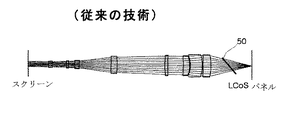
このように、LCoSパネルで反射された光が、平板型PBSを透過するとき、非点収差が大きく発生する。この現象について、図6ないし図8を参照しながら説明する。
図6は、光が平板型PBSを透過する場合の投射レンズのレイアウト構成図であって、図7と図8は図6の場合における断面図である。
シミュレーターを利用して斜角で挿入された平板型PBS50が、スクリーンとLCoSパネル間にある場合を説明すれば次の通りである。
As described above, when the light reflected by the LCoS panel is transmitted through the flat PBS, astigmatism is greatly generated. This phenomenon will be described with reference to FIGS.
FIG. 6 is a layout configuration diagram of a projection lens when light passes through a flat-plate PBS, and FIGS. 7 and 8 are cross-sectional views in the case of FIG.
The case where the
図6のように、光が投射レンズとLCoSパネル間に斜角で挿入された平板型PBS50を透過する場合の収差特性は、図7と図8のようである。
すなわち、図面に示すように、光が投射レンズとLCoSパネル間に斜角で挿入された平板型PBS50を透過する場合には、非点収差が発生する問題点がある。
このように、従来の反射型照明系はいろいろ問題点を有する。
As shown in FIG. 6, the aberration characteristics when light passes through the
That is, as shown in the drawing, when light passes through the flat-
As described above, the conventional reflective illumination system has various problems.
図1で説明した3PBSシステムの反射型照明系は、全体の光経路が3段構成を有するものであってシステムの大きさが大きくなって、システムを構成するのに多くの部品を必要とする。
図2で説明したカラークオード(Color Quad)システムの反射型照明系は、2段構成で全体構造が単純化されたが、4個のカラーセレクターとPBSを含むために価格面で有利でない。
また、PBSでP/S分離及び合成をする過程で、入力された波が出力される時、他の成分の偏光を有するようになる光弾性問題がありうる。
The reflection type illumination system of the 3PBS system described with reference to FIG. 1 has a three-stage overall light path, which increases the size of the system and requires many parts to configure the system. .
Although the overall structure of the reflection type illumination system of the color quad system described in FIG. 2 is simplified by a two-stage configuration, it is not advantageous in terms of cost because it includes four color selectors and a PBS.
Also, in the process of P / S separation and synthesis in the PBS, when an input wave is output, there may be a photoelastic problem in that the input wave has polarization of another component.
図3と図4で説明した平板型PBSを用いる反射型照明系は、光弾性問題と価格的な問題、低い照明効率などの問題は解決されるが、光が平板型PBSを透過することによって収差問題が発生するようになる。
非点収差を減らす方法として、挿入された平板型PBSの厚さを薄くしたり、二個の平板型PBSを相異なる方向に配置する方法を用いる場合にも、次のような問題がある。すなわち、挿入された板の厚さが薄くなれば板自体が曲がる問題が発生して、板の配置を相異なるようにすることは非点収差を相殺させることでなく、単にスポット(Spot)の形態を円形に作ったことに過ぎなく、スポットの大きさを増加させる。また、両板の角度は非常に異なる角度を持っていて一平面上に照明系を構成できなくなる。
The reflection-type illumination system using the flat PBS described with reference to FIGS. 3 and 4 can solve the problems of photoelasticity, cost, and low illumination efficiency. An aberration problem occurs.
As a method of reducing astigmatism, the following problems are also encountered when using a method of reducing the thickness of an inserted flat PBS or arranging two flat PBSs in different directions. In other words, if the thickness of the inserted plate becomes thinner, the problem that the plate itself bends occurs. Making the arrangement of the plates different does not cancel out the astigmatism, but simply creates the spot. It is just a circular shape and increases the spot size. Also, the angles of the two plates are very different, making it impossible to form an illumination system on one plane.
本発明は、前記のような従来技術の照明光学系の問題を解決するためのものであって、プロジェクションシステムのLCoSパネルで反射された赤色光R、緑色光G、及び青色光Bの信号が、平板型PBSを透過せず反射し、投射レンズに入射されるようにして非点収差の発生を抑制し、照明効率を高めた反射型照明光学系を提供することを目的とする。 The present invention is to solve the above-described problems of the conventional illumination optical system, and the signals of the red light R, the green light G, and the blue light B reflected by the LCoS panel of the projection system are used. It is another object of the present invention to provide a reflection-type illumination optical system in which the light is reflected without being transmitted through a flat-type PBS and is incident on a projection lens to suppress the generation of astigmatism and improve the illumination efficiency.
本発明による反射型照明光学系は、ランプから照射されて偏光成分が整列された光を受けて青色光Bの光を透過し、緑色光G及び赤色光Rの光を反射する二つの経路に分離する第1ダイクロイックミラーと;前記経路が分離された光を受けて、赤の光は透過して緑の光は反射する第2ダイクロイックミラーと;前記経路がそれぞれ分離された赤色光R、緑色光G、青色光Bの光をそれぞれ透過する第1、第2、第3の平板(平板)型PBSと;前記第1、第2、第3の平板型PBSを透過したそれぞれの光を、位相を変えて反射する第1、2、3LCoSパネルと;前記第1、第2、第3のLCoSパネルで反射し再び第1、第2、第3の平板型PBSにより反射した赤色光R、緑色光G、及び青色光Bの光を合成して、投射レンズに入射させるX−プリズムが含まれることを特徴とする。 The reflection-type illumination optical system according to the present invention includes two paths that receive light of which polarization components are aligned by being irradiated from a lamp, transmit blue light B, and reflect green light G and red light R. A first dichroic mirror that separates the light; a second dichroic mirror that receives the separated light and transmits the red light and reflects the green light; red light R and green light whose paths are separated from each other; A first, a second, and a third flat-plate (flat) PBS that respectively transmit light G and a blue light B; and a light that transmits through the first, second, and third flat-type PBS, respectively. First, second, and third LCoS panels that change the phase and reflect light; red light R that is reflected by the first, second, and third LCoS panels and reflected again by the first, second, and third plate-type PBSs; The light of the green light G and the light of the blue light B are combined and incident on the projection lens. Characterized to include that X- prism.
本発明による反射型照明光学系は、光を放出するランプと、前記ランプから放出されて偏光成分が整列された赤色光、緑色光、及び青色光をそれぞれの経路に分離するダイクロイックミラーと、前記赤色光、緑色光、及び青色光を、位相を変えて反射する第1、第2、第3のLCoSパネルと、前記ダイクロイックミラーによりそれぞれの経路に分離された光が透過し、前記第1、第2、第3のLCoSパネルで位相が変わって反射した光が反射される平板型PBSと、前記平板型PBSで反射されたそれぞれの光を合成して投射レンズに入射するようにするX−プリズムが含まれることを特徴とする。 A reflective illumination optical system according to the present invention includes a lamp that emits light, a dichroic mirror that separates red light, green light, and blue light emitted from the lamp and whose polarized components are aligned into respective paths, First, second, and third LCoS panels that change the phase of red light, green light, and blue light and reflect the light separated into respective paths by the dichroic mirror; An X- plate for combining light reflected by the flat-type PBS with light reflected by the flat-type PBS and light incident on the projection lens by combining the respective light reflected by the flat-type PBS with the second and third LCoS panels. It is characterized by including a prism.
本発明による反射型照明光学系は、次のような効果がある。
反射型3板式光学系の構成時に、平板型PBSを用いて光弾性問題を解決する効果がある。
また、X−プリズムと平板型PBSの間に、偏光板を挿入した構造であるために、小さいF/#においても、P/S分離及び合成をすることができて投射レンズに入射する光のコントラストを向上させることができる。
また、投射レンズに入射する光は、平板型PBSで反射されて投射レンズに入射されるので、非点収差が発生しないようにする効果を有する。
The reflective illumination optical system according to the present invention has the following effects.
In the configuration of the reflection type three-plate optical system, there is an effect of solving the photoelasticity problem by using the flat plate type PBS.
In addition, since a polarizing plate is inserted between the X-prism and the flat-type PBS, P / S separation and synthesis can be performed even in a small F / #, so that light incident on the projection lens can be reduced. The contrast can be improved.
In addition, since the light incident on the projection lens is reflected by the flat PBS and is incident on the projection lens, it has an effect of preventing astigmatism from occurring.
また、光の経路を3段または2段で構成する場合、システムの大きさが大きくなって、システムを構成するのに多くの部品を必要とする従来の技術に比べて、全体構造が単純化されて価格面で有利である。 Also, when the light path is configured in three or two stages, the size of the system becomes large, and the overall structure is simplified as compared with the conventional technology that requires many components to configure the system. Being price advantageous.
本発明による反射型照明光学系の望ましい実施例に関して、添付した図面を参照しながら詳細に説明すると次の通りである。
図9は、本発明による反射型照明光学系の構成図である。
本発明は、反射型パネルであるLCoSを利用したプロジェクションディスプレィ装置の照明系に係り、平板型PBSを利用して優秀な性能を有して、価格が低廉な新しい形態の3板式反射型照明系を提供する。
A preferred embodiment of the reflective illumination optical system according to the present invention will be described in detail with reference to the accompanying drawings.
FIG. 9 is a configuration diagram of a reflective illumination optical system according to the present invention.
BACKGROUND OF THE INVENTION 1. Field of the Invention The present invention relates to an illumination system of a projection display apparatus using LCoS, which is a reflection type panel, and a new type of three-panel reflection illumination system which has excellent performance using a flat type PBS and is inexpensive. I will provide a.
本発明はフィルムタイプの平板型PBSを用いるが、非点収差が発生しないようにするために、LCoSパネルで反射して投射レンズに入射される赤色光R、緑色光G、青色光Bの光は、すべて平板型PBSを透過せずに反射されて入射する。
すなわち、従来のPBSの光弾性問題によるコントラスト低下及び光量低下問題を解決するために、PBSと同一機能(P/S分離及び合成)を遂行する偏光フィルムである平板型PBSを用いる。
In the present invention, a film-type flat PBS is used. In order to prevent astigmatism from occurring, light of red light R, green light G, and blue light B reflected by the LCoS panel and incident on the projection lens is used. Are incident without being transmitted through the flat-plate type PBS.
That is, in order to solve the problem of the decrease in contrast and the amount of light due to the photoelastic problem of the conventional PBS, a flat-type PBS, which is a polarizing film performing the same function (P / S separation and synthesis) as the PBS, is used.
本発明はこのような平板型PBSにより、従来のPBSより小さいF/#においてもP/S分離及び合成をすることができ、さらに明るい照明系を実現し、フィルムタイプの平板型PBSに反射されて投射レンズに入射する光のコントラストを向上させるために、X−プリズムと平板型PBSの間に偏光板を挿入した構造を有する。 According to the present invention, P / S separation and synthesis can be performed even with F / # smaller than the conventional PBS by using such a flat-type PBS, a brighter illumination system is realized, and the light is reflected by the film-type flat-type PBS. In order to improve the contrast of light incident on the projection lens, a polarizing plate is inserted between the X-prism and the flat PBS.
ここで、「F/#」は照明光の角度を示すものである。そのため、F/#が小さいほど照明光の角度が大きくなる。このように、照明角度が大きくなる場合に多くの光を受けることができる。
このような本発明による反射型照明光学系の一実施例は、図9に示される。
まず、赤色光R、緑色光G、青色光Bを照射するランプ31と、ランプ31から照射されてPCS(Polarization Converting System)を介して一方向に偏光成分が整列された光を受けて、青Bの光を透過して緑G、赤Rの光を反射する二つの経路に分離する第1ダイクロイックミラー32aと、第1リレーレンズ33aを通して反射された黄色(G+R)の光を受光し、赤色光を透過して緑色光を反射する第2ダイクロイックミラー32bと、第2ダイクロイックミラー32bにより反射された緑色光を、第2LCoSパネル35bに透過させる第2平板型PBS34bと、第2ダイクロイックミラー32bを透過した赤色光を、第1LCoSパネル35aに透過する第1平板型PBS34aと、第1ダイクロイックミラー32aを介して、第2リレーレンズ33b、ミラー、第3リレーレンズ33cを経て入射する青色光を、第3LCoSパネル35cに透過する第3平板型PBS34cと、第1、第2、第3のLCoSパネル35a、35b、35cにより反射され、それぞれ第1、第2、第3の平板型PBS34a、34b、34cにより反射される赤色光R、緑色光G、青色光Bを合成して、投射レンズ38に入射させるX−プリズム36と、X−プリズム36に入射する前にコントラストを高めるために、赤色光R、緑色光G、青色光Bそれぞれの光を偏光する第1、第2、第3の偏光板37a、37b、37cから構成される。
Here, “F / #” indicates the angle of the illumination light. Therefore, the smaller the F / #, the larger the angle of the illumination light. As described above, a large amount of light can be received when the illumination angle increases.
One embodiment of such a reflective illumination optical system according to the present invention is shown in FIG.
First, a
このような本発明による反射型照明光学系は、第1ダイクロイックミラー32aにより、一番目に反射された黄色(緑+赤)の光は、第2ダイクロイックミラー(Green Dicroic Mirror)に入射して反射した緑色光が、第2平板型PBS34bを透過して第2LCoSパネル35bに入射されて、透過した赤色光は、第1平板型PBS34aを透過して第1LCoSパネル35aに入射される。
In such a reflective illumination optical system according to the present invention, the yellow (green + red) light first reflected by the first
そして、第1ダイクロイックミラー32aを透過した青色光は、リレーレンズ33b、33cを経て、第3平板型PBS34cを透過して第3LCoSパネル35cに入射される。
このように第1、第2、第3のLCoSパネル35a、35b、35cに入射した赤色光R、緑色光G、青色光Bは、第1、第2、第3のLCoSパネル35a、35b、35cによって反射され、反射された光は、第1、第2、第3の各LCoSパネル35a、35b、35cの前にある第1、第2、第3の平板型PBS34a、34b、34cによって反射されてX−プリズム36に入射される。
Then, the blue light transmitted through the first
The red light R, the green light G, and the blue light B incident on the first, second, and
ここで、第1、第2、第3の平板型PBS34a、34b、34cによって反射された赤色光R、緑色光G、青色光Bの光は、コントラストを高めるためにX−プリズム36に入射する前に、それぞれ第1、第2、第3の偏光板37a、37b、37cを経てX−プリズム36に入射する。
このような本発明による反射型照明系は、光学的性能に異常を起こさず、平板型PBSのような板形状の光学部品を照明系に用いることができる構造を有し、反射型照明系に使われるPBSの光弾性問題によるコントラスト低下及び光量低下問題を解決する。
Here, the red light R, green light G, and blue light B reflected by the first, second, and third plate-
Such a reflective illumination system according to the present invention has a structure in which a plate-shaped optical component such as a flat-type PBS can be used for the illumination system without causing any abnormality in optical performance. It solves the problem of the decrease in contrast and the amount of light due to the photoelasticity of the PBS used.
以下に、本発明による反射型照明光学系の非点収差特性を説明する。
図10は、LCoSパネルで反射された光が、平板型PBSを透過せず、反射する場合の投射レンズのレイアウト構成図であって、図11と図12は図10の場合における断面図である。
図6ないし図8と比較すると、LCoSパネルで反射された光が平板型PBSを透過せずに反射する場合の収差特性は、図11と図12のように非点収差が発生しないことがわかる。
Hereinafter, the astigmatism characteristics of the reflective illumination optical system according to the present invention will be described.
FIG. 10 is a layout configuration diagram of a projection lens in a case where light reflected by the LCoS panel does not transmit through the flat PBS and reflects the light. FIG. 11 and FIG. 12 are cross-sectional views in the case of FIG. .
Compared with FIGS. 6 to 8, it can be seen that the aberration characteristics when the light reflected by the LCoS panel is reflected without passing through the flat PBS does not cause astigmatism as shown in FIGS. .
光が平板型PBSによって反射されて、投射レンズに入射される構造を有する本発明による光学系では、LCoSパネルで反射された光が平板型PBSを透過しないので、非点収差が発生しない。
また、平板型PBSの厚さを厚くして構造物に取付ける場合、曲がる問題を除去することができて、光学性能に影響を与えない。
In the optical system according to the present invention having a structure in which light is reflected by the flat PBS and is incident on the projection lens, astigmatism does not occur because the light reflected by the LCoS panel does not pass through the flat PBS.
In addition, when the plate-type PBS is mounted on a structure with a large thickness, the bending problem can be eliminated, and the optical performance is not affected.
以上説明した内容を通じて、当業者ならば本発明の技術思想を逸脱しない範囲で、多様な変更及び修正が可能なことがわかることである。
したがって、本発明の技術的範囲は、実施例に記載された内容に限定されることでなく特許請求の範囲によって決まらなければならない。
From the above description, those skilled in the art will appreciate that various changes and modifications can be made without departing from the spirit of the present invention.
Therefore, the technical scope of the present invention is not limited to the contents described in the embodiments, but must be determined by the appended claims.
本発明は、反射型3板式光学系の構成時に平板型PBSを用いて光弾性問題を解決することができ、X−プリズムと平板型PBSの間に偏光板を挿入した構造であるために、小さいF/#でもP/S分離及び合成をすることができ、投射レンズに入射する光のコントラストを向上させることができる。
また、投射レンズに入射する光は、平板型PBSで反射されて投射レンズに入射するので、非点収差が発生しないようにする効果を有する。
The present invention can solve the photoelasticity problem by using a flat-type PBS when configuring a reflective three-plate optical system, and has a structure in which a polarizing plate is inserted between the X-prism and the flat-type PBS. Even with a small F / #, P / S separation and synthesis can be performed, and the contrast of light incident on the projection lens can be improved.
Further, since the light incident on the projection lens is reflected by the flat PBS and is incident on the projection lens, it has an effect of preventing astigmatism from occurring.
また、光の経路が3段または2段で構成する場合、システムの大きさが大きくなって、システムを構成するのに多くの部品を必要とする従来の技術に比べて、全体構造が単純化されて価格面で有利である。 Also, when the light path is configured in three or two stages, the size of the system becomes large, and the overall structure is simplified as compared with the conventional technology that requires many components to configure the system. Being price advantageous.
1;ランプ
2;第1ダイクロイックミラー
3;第2ダイクロイックミラー
4a、4b、4c;第1、第2、第3のPBS
5a、5b、5c;第1、第2、第3のLCoSパネル
6;X−プリズム
7;ランプ
8a、8b、8c、8d;第1、第2、第3、第4のカラーセレクター
9a、9b、9c、9d;第1、第2、第3、第4のPBS
10a、10b、10c;第1、第2、第3のLCoSパネル
11;ランプ
12a、12b;第1、第2のダイクロイックミラー
13a、13b;第1、第2の平板型PBS
14;カラーセレクター
15a、15b、15c;第1、第2、第3のLCoSパネル
16;ランプ
17;第1ダイクロイックミラー
18a、18b、18c;第1、第2、第3のリレーレンズ
19;第2ダイクロイックミラー
20a、20b、20c;第1、第2、第3の平板型PBS
21a、21b、21c;第1、第2、第3のLCoSパネル
22;X−プリズム
23;投射レンズ
31;ランプ
32a、32b;第1、第2のダイクロイックミラー
33a、33b、33c;第1、第2、第3のリレーレンズ
34a、34b、34c;第1、第2、第3の平板型PBS
35a、35b、35c;第1、第2、第3のLCoSパネル
36;X−プリズム
37a、37b、37c;第1、第2、第3の偏光板
50;平板型PBS
1; lamp 2; first dichroic mirror 3; second
5a, 5b, 5c; first, second, and third LCoS panels 6; X-prism 7;
10a, 10b, 10c; first, second and
14;
21a, 21b, 21c; first, second,
35a, 35b, 35c; first, second, and third LCoS panels 36; X-prisms 37a, 37b, 37c; first, second, and third
Claims (7)
前記経路が分離された光を受光して、赤色光は透過し、緑色光は反射する第2ダイクロイックミラーと、
前記経路が分離された赤色光、緑色光、青色光を、それぞれ透過する第1、第2、第3の平板型PBSと、
前記第1、第2、第3の平板型PBSを透過したそれぞれの光を、位相を変えて反射する第1、2、3のLCoSパネルと、
前記第1、第2、第3のLCoSパネルで反射され、再び前記第1、第2、第3の平板型PBSにより反射した赤色光、緑色光、及び青色光を合成して、投射レンズに入射させるX−プリズムを含むことを特徴とする反射型照明光学系。 A first dichroic mirror that receives light radiated from the lamp and whose polarization components are aligned, transmits blue light, and separates the light into two paths that reflect green light and red light;
A second dichroic mirror that receives the light separated by the path, transmits red light, and reflects green light;
A first, a second, and a third plate-type PBS that respectively transmit the red light, the green light, and the blue light whose paths are separated;
First, second and third LCoS panels for changing the phases of the respective lights transmitted through the first, second and third plate-type PBSs, and
The red, green, and blue lights reflected by the first, second, and third LCoS panels and reflected again by the first, second, and third plate-type PBSs are combined to form a projection lens. A reflective illumination optical system comprising an X-prism for incidence.
前記ランプから放出され、偏光成分が整列された青色光、緑色光、及び赤色光を、それぞれの経路に分離するダイクロイックミラーと、
前記青色光、緑色光、及び赤色光のそれぞれの位相を変えて反射する第1、第2、第3のLCoSパネルと、
前記ダイクロイックミラーにより、それぞれの経路に分離された前記光を透過し、前記第1、第2、第3のLCoSパネルで位相が変えられた光を反射する平板型PBSと、
前記平板型PBSで反射されたそれぞれの光を合成し、投射レンズに入射されるようにするX−プリズムとを含むことを特徴とする反射型照明光学系。 A lamp that emits light,
A dichroic mirror that separates blue light, green light, and red light emitted from the lamp and whose polarization components are aligned into respective paths;
First, second, and third LCoS panels that reflect while changing the phases of the blue light, the green light, and the red light,
A flat PBS that transmits the light separated into respective paths by the dichroic mirror and reflects the light whose phase has been changed by the first, second, and third LCoS panels;
A reflection type illumination optical system, comprising: an X-prism that combines respective lights reflected by the flat-type PBS so as to be incident on a projection lens.
前記緑色光、赤色光のうち、赤色光を透過し、緑色光を反射する第2ダイクロイックミラーで形成されていることを特徴とする請求項3に記載の反射型照明光学系。 A first dichroic mirror that transmits blue light and reflects green light and red light,
4. The reflection-type illumination optical system according to claim 3, wherein a second dichroic mirror that transmits red light out of the green light and the red light and reflects the green light is formed.
The reflective illumination optical system according to claim 3, wherein the flat PBS is a film type.
Applications Claiming Priority (1)
| Application Number | Priority Date | Filing Date | Title |
|---|---|---|---|
| KR1020030021271A KR100546644B1 (en) | 2003-04-04 | 2003-04-04 | Reflective type lighting optical system |
Publications (1)
| Publication Number | Publication Date |
|---|---|
| JP2004310103A true JP2004310103A (en) | 2004-11-04 |
Family
ID=33095632
Family Applications (1)
| Application Number | Title | Priority Date | Filing Date |
|---|---|---|---|
| JP2004111278A Pending JP2004310103A (en) | 2003-04-04 | 2004-04-05 | Reflective illuminating optical system |
Country Status (4)
| Country | Link |
|---|---|
| US (1) | US7172287B2 (en) |
| JP (1) | JP2004310103A (en) |
| KR (1) | KR100546644B1 (en) |
| CN (1) | CN100394250C (en) |
Cited By (1)
| Publication number | Priority date | Publication date | Assignee | Title |
|---|---|---|---|---|
| CN115484443A (en) * | 2021-05-31 | 2022-12-16 | 立景光电股份有限公司 | Projection device |
Families Citing this family (5)
| Publication number | Priority date | Publication date | Assignee | Title |
|---|---|---|---|---|
| US7347561B2 (en) * | 2001-08-06 | 2008-03-25 | Jds Uniphase Corporation | Image display device |
| US7963658B2 (en) * | 2005-06-09 | 2011-06-21 | Hewlett-Packard Development Company, L. P. | Light modulator assembly |
| JP2009047819A (en) * | 2007-08-17 | 2009-03-05 | Sony Corp | Polarizing beam splitter, projection type optical equipment, and projection type display device |
| WO2009101236A1 (en) * | 2008-02-13 | 2009-08-20 | Nokia Corporation | Display device and a method for illuminating a light modulator array of a display device |
| KR101033602B1 (en) * | 2009-06-09 | 2011-05-11 | 엘지전자 주식회사 | Projector |
Citations (6)
| Publication number | Priority date | Publication date | Assignee | Title |
|---|---|---|---|---|
| JPH1115074A (en) * | 1997-06-20 | 1999-01-22 | Sharp Corp | Projection type picture display device |
| JPH11119161A (en) * | 1997-10-15 | 1999-04-30 | Nikon Corp | Polarizing device and projection type display device |
| JPH11160654A (en) * | 1997-11-25 | 1999-06-18 | Sharp Corp | Reflection projector |
| JPH11202432A (en) * | 1998-01-16 | 1999-07-30 | Sharp Corp | Projection type image display device |
| JP2000180815A (en) * | 1998-12-16 | 2000-06-30 | Victor Co Of Japan Ltd | Reflection type projector device |
| JP2004126496A (en) * | 2002-08-05 | 2004-04-22 | Hitachi Ltd | Optical unit and projection type video display device using optical unit |
Family Cites Families (12)
| Publication number | Priority date | Publication date | Assignee | Title |
|---|---|---|---|---|
| US6497485B1 (en) * | 2000-01-20 | 2002-12-24 | Seiko Epson Corporation | Image projection system having uniform brightness |
| KR100601608B1 (en) * | 1999-06-03 | 2006-07-14 | 삼성전자주식회사 | Color projector |
| US6191893B1 (en) * | 1999-06-04 | 2001-02-20 | Philips Electronics North America Corporation | Color projection display system with improved hue variation |
| WO2002037175A1 (en) * | 2000-11-02 | 2002-05-10 | 3M Innovative Properties Company | Optical systems for reflective lcds |
| KR100534575B1 (en) * | 2001-04-24 | 2005-12-07 | 삼성에스디아이 주식회사 | Light Converting Apparatus of Projection System |
| JP2003029331A (en) * | 2001-07-13 | 2003-01-29 | Sano Fuji Koki Co Ltd | Reflection type liquid-crystal projector |
| CN2513131Y (en) * | 2001-08-10 | 2002-09-25 | 浙江大学 | Liquid crystal projector polarizing dividing and synthesizing device using reflective liquid crystal plate image source |
| US6714350B2 (en) * | 2001-10-15 | 2004-03-30 | Eastman Kodak Company | Double sided wire grid polarizer |
| CN2510883Y (en) * | 2001-12-28 | 2002-09-11 | 北京澳柯玛视美乐信息技术有限公司 | Reflection-type silicon-base liquid-crystal projector optical mechanism |
| WO2003063509A1 (en) * | 2002-01-07 | 2003-07-31 | 3M Innovative Properties Company | Color component aperture stops in projection display system |
| JP2005519326A (en) * | 2002-02-28 | 2005-06-30 | スリーエム イノベイティブ プロパティズ カンパニー | Compound polarization beam splitter |
| US6758565B1 (en) * | 2003-03-20 | 2004-07-06 | Eastman Kodak Company | Projection apparatus using telecentric optics |
-
2003
- 2003-04-04 KR KR1020030021271A patent/KR100546644B1/en not_active IP Right Cessation
-
2004
- 2004-04-02 US US10/816,998 patent/US7172287B2/en not_active Expired - Fee Related
- 2004-04-05 CN CNB2004100310201A patent/CN100394250C/en not_active Expired - Fee Related
- 2004-04-05 JP JP2004111278A patent/JP2004310103A/en active Pending
Patent Citations (6)
| Publication number | Priority date | Publication date | Assignee | Title |
|---|---|---|---|---|
| JPH1115074A (en) * | 1997-06-20 | 1999-01-22 | Sharp Corp | Projection type picture display device |
| JPH11119161A (en) * | 1997-10-15 | 1999-04-30 | Nikon Corp | Polarizing device and projection type display device |
| JPH11160654A (en) * | 1997-11-25 | 1999-06-18 | Sharp Corp | Reflection projector |
| JPH11202432A (en) * | 1998-01-16 | 1999-07-30 | Sharp Corp | Projection type image display device |
| JP2000180815A (en) * | 1998-12-16 | 2000-06-30 | Victor Co Of Japan Ltd | Reflection type projector device |
| JP2004126496A (en) * | 2002-08-05 | 2004-04-22 | Hitachi Ltd | Optical unit and projection type video display device using optical unit |
Cited By (3)
| Publication number | Priority date | Publication date | Assignee | Title |
|---|---|---|---|---|
| CN115484443A (en) * | 2021-05-31 | 2022-12-16 | 立景光电股份有限公司 | Projection device |
| CN115484443B (en) * | 2021-05-31 | 2024-02-20 | 立景光电股份有限公司 | Projection device |
| US11962945B2 (en) | 2021-05-31 | 2024-04-16 | Himax Display, Inc. | Projection apparatus |
Also Published As
| Publication number | Publication date |
|---|---|
| US20040196437A1 (en) | 2004-10-07 |
| US7172287B2 (en) | 2007-02-06 |
| CN100394250C (en) | 2008-06-11 |
| KR100546644B1 (en) | 2006-01-26 |
| CN1542493A (en) | 2004-11-03 |
| KR20040087034A (en) | 2004-10-13 |
Similar Documents
| Publication | Publication Date | Title |
|---|---|---|
| JP2004020621A (en) | Reflection type image projection apparatus, projection type image display using the same, and light source apparatus to be used therefor | |
| WO2001025838A1 (en) | Reflection type liquid crystal projector | |
| US20030218724A1 (en) | Optical unit and projection type projector apparatus using the same | |
| KR20020043666A (en) | Optical System Of Liquid Crystal Projector | |
| KR100546644B1 (en) | Reflective type lighting optical system | |
| JP2002207193A (en) | Color separating/synthesizing apparatus | |
| US7717567B2 (en) | Lighting optical system | |
| JP4154718B2 (en) | Reflective illumination optical system | |
| JP2002365591A (en) | Optical unit and video display device using the same | |
| KR100763396B1 (en) | Optical Lighting System | |
| JP5538796B2 (en) | Image projection device | |
| JP2011095404A (en) | Image display device | |
| US6831788B2 (en) | Polarization beam splitter and projection display apparatus using the same | |
| JP3000993B2 (en) | LCD projector | |
| KR100252982B1 (en) | Polarized light conversion device for liquid crystal projector | |
| US20050041288A1 (en) | Polarization conversion module and polarization conversion method thereof | |
| KR100421859B1 (en) | optical system of projection-type video display appliance | |
| TW594367B (en) | Reflective LCD projector | |
| KR100755859B1 (en) | Reflection-type optical system | |
| JP5104338B2 (en) | projector | |
| JP2005106901A (en) | Image projection device | |
| KR100232183B1 (en) | Liquid crystal projector | |
| JP2000035612A (en) | Color picture projection device | |
| KR20040020333A (en) | Projection system | |
| KR20080010132A (en) | Reflective type projection system |
Legal Events
| Date | Code | Title | Description |
|---|---|---|---|
| A621 | Written request for application examination |
Free format text: JAPANESE INTERMEDIATE CODE: A621 Effective date: 20070323 |
|
| A977 | Report on retrieval |
Free format text: JAPANESE INTERMEDIATE CODE: A971007 Effective date: 20090520 |
|
| A131 | Notification of reasons for refusal |
Free format text: JAPANESE INTERMEDIATE CODE: A131 Effective date: 20090527 |
|
| A521 | Written amendment |
Free format text: JAPANESE INTERMEDIATE CODE: A523 Effective date: 20090826 |
|
| A02 | Decision of refusal |
Free format text: JAPANESE INTERMEDIATE CODE: A02 Effective date: 20091021 |