JP2004309629A - Light guide structure for status indicator - Google Patents
Light guide structure for status indicator Download PDFInfo
- Publication number
- JP2004309629A JP2004309629A JP2003100281A JP2003100281A JP2004309629A JP 2004309629 A JP2004309629 A JP 2004309629A JP 2003100281 A JP2003100281 A JP 2003100281A JP 2003100281 A JP2003100281 A JP 2003100281A JP 2004309629 A JP2004309629 A JP 2004309629A
- Authority
- JP
- Japan
- Prior art keywords
- light
- status indicator
- housing
- shaped groove
- light guide
- Prior art date
- Legal status (The legal status is an assumption and is not a legal conclusion. Google has not performed a legal analysis and makes no representation as to the accuracy of the status listed.)
- Pending
Links
Images


Abstract
Description
【0001】
【発明の属する技術分野】
本発明は、殆どの携帯端末機に設けられている待受け、送信、受信等の機器の状態を表示する状態表示器において、携帯端末機を手に持って使用したり、腰、肩、車載等様々な使用状態にあっても、どの方向からでも状態の確認ができるように、視認性の向上を図った状態表示器の導光構造に関するものである。
【0002】
【従来の技術】
従来の携帯端末機の状態表示器は、以下のようなものがある。すなわち、少なくとも一面を表示面とする透明多面体と透明多面体の他の一面に対向配設して光を入射する発光素子とからなり、透明多面体は表示面に向けて発光素子の入射光を反射する反射面と光導波路とを備え構成されている(例えば、特許文献1参照)。
【0003】
また、直角透光窓の内表面に、発光ダイオードの発光面へ対向する状態で、多面体状の透明凸部を形成し、発光ダイオードからの光線の一部は透明凸部を形成し、透明凸部内に入射して屈折し、さらに透明凸部表面で全反射して、発光ダイオードの発光面へ対向していない側における透明面側からも射出されるように構成されているものもある(例えば、特許文献2参照)。
【0004】
また、断面が長方形に形成された導光装置の下面(内)側に断面が三角形の切り込みを設け、この切り込みの下側に発光手段を設け、発光手段からの光線が切り込みに向かって照射されることによって平面に形成される反射面で反射されて導光装置の正面が発光されると共に、この照射された光線が反射面を透過して導光装置の上面も発光され、これにより外側の2面がそれぞれ発光されるように構成されているものもある(例えば、特許文献3参照)。
【0005】
また、外装ケースの凸面部に表示窓を設け、表示窓から先端レンズ部を外部に露出させて外装ケースの内部に導光体を配設し、導光体の入光面に対向させて外装ケースの内部に収容した回路基板上に発光素子を設け、発光素子からの光を導光体を介して先端レンズ部に導いて外部に放射させる電子機器の機能表示ランプ構造において、導光体に、発光素子から入射された光を、先端レンズ部を通して外装ケースの正面に向けて出射させる第1反射面と、先端レンズ部を通し外装ケースの側方に向けて発光素子からの光を出射させる第2反射面とを設けたものもある(例えば、特許文献4参照)。
【0006】
また、光源から放射された光が、導光発光部の係合部から入射され、導光発光部内にて光拡散され、拡散された光が、窪み部の底面部と側面部の表面で反射し、その反射した光が窪み部の表面近傍の導光発光部材によりさらに光拡散されて発光し、窪み部近傍の導光発光部の輝度を高めることができるように構成されているものもある(例えば、特許文献5参照)。
【0007】
また、透明樹脂からなる導光板の端部上面に光源部を設け、光源部には、光の出射方向が導光板の光出射面と垂直になるようにして発光素子をインサート形成し、導光板の端部においては発光素子の下方を斜めにカットして反射面を形成するようにしたものもある(例えば、特許文献6参照)。
【0008】
【特許文献1】
特開平08−184713号公報
【特許文献2】
特開平11−023817号公報
【特許文献3】
特開平10−199314号公報
【特許文献4】
特開2002−168981号公報
【特許文献5】
特開2002−271456号公報
【特許文献6】
特開平09−160032号公報
【0009】
【発明が解決しようとする課題】
しかしながら、前記特許文献2、3、4に示されているものは、実用化はされているが、いずれも防水構造での実用化が難しいという課題がある。すなわち、防水構造では、防水用接合面を確保する必要があるが、接合面が正面と天面の2面にまたがっており、2面の防水構造はコスト及び信頼性に劣る。また1面で処理しようとするとスペースが必要であり、現実的ではない。
【0010】
さらには、各特許文献に示されているものは、それぞれ、光を反射させて、状態表示器の視認性を向上させるようにしているが、状態表示器は携帯端末機の操作性を考え、携帯端末機の表面から突出していないため、特許文献2、3、4に示されるものは、状態表示器の正面及び天面方向からの視認性は良いが、下面方向からの視認性は劣り、他の文献のものは、状態表示器の正面方向からの視認性は良いが、他方向からの視認性が劣るという問題がある。
【0011】
本発明は、上述した事情に鑑みてなされたものであり、携帯端末機の状態表示器を正面、上下面のどの方向からでも視認性が高く、防水構造が容易に実現できる状態表示器の導光構造を提供することを目的とする。
【0012】
【課題を解決するための手段】
上述した課題を解決するため、本発明は、発光体からの光を透過させることにより状態を表示可能な状態表示器の導光構造において、前記状態表示器には、外部へ光が出射される出射面側が開口部となる断面略V字状のV字溝が、前記発光体と互いに対向する位置に形成されており、V字溝の斜面は発光体からの光を前記出射面端部方向へ屈曲させるように構成されていることを特徴としたものである。
【0013】
また、本発明において、前記状態表示器の前記出射面は細長形状を有しており、前記出射面の長手方向中央位置に短手方向全長に渡って前記V字溝が形成されていることを特徴とするものである。
【0014】
【発明の実施の形態】
以下、本発明の実施の形態を図面を用いて説明する。
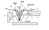
図1は、本発明の実施の形態を示す正面図、図2は図1のA−A線断面図、図3は筐体内側を示す外観図、図4は筐体外側を示す外観図である。
【0015】
本発明の実施の形態における状態表示器10は、光の出射面10aを有する楕円形状の表示部10bと、表示部10bよりも大径の楕円形状を有し、状態表示器10の筐体12への接合部となるフランジ部10cと発光体14と対面配置される入射部10eとにより構成されている。表示部10bの大径方向中央位置には、小径方向全長に渡って、出射面10a側が開口部となるV字溝10fが形成されており、V字の斜面が光を反射する反射面10g及び10hを構成している。各反射面10g及び10hの角度C及びDは、それぞれ略45°である。
【0016】
筐体12には、状態表示器10の表示部10bを収納可能な楕円形状の収納穴12aが形成されており、収納穴12aの周囲には、状態表示器10のフランジ部10cを接合可能な平滑度の高い面である筐体受け面12bが形成されている。
【0017】
状態表示器10は、出射面10aが筐体12の外面12cから外方に、図2に示す距離A及び距離Bだけ突出するように表示部10bが収納穴12a内に収納されるとともに、フランジ部10cが筐体受け面12bと接合するように筐体10の内側から配設される。この際、入射部10eは筐体12内部に配設される発光体14と対面し、V字溝10fは発光体14の垂直上方に位置する。
【0018】
フランジ部10cと筐体受け面12bとは、超音波溶着や両面テープなどにより防水構造となるように取り付けられており、筐体受け面12bが鋭角部の無い円弧状の断面形状を有し、平滑度の高い面に形成されているため、互いに接合し易く、超音波溶着や両面テープなどにより容易に防水構造とすることができる。
【0019】
次に、作用について説明する。
発光体14からの光は、入射部10eを通過して表示部10bへ至るが、V字溝10fの底部及びV字溝10fが形成されていない部分を通過する光は光路16のように直進して出射面10aから状態表示器10の正面方向へ放射される。
【0020】
一方、V字溝10fの反射面10g方向へ通過する光は、光路18のように反射面10gで反射して出射面10aの上面側端部方向へ屈曲し、上面側端部から筐体12の外部上方へ放射される。また、反射面10hを通過する光は、光路20のように反射面10hで反射して出射面10aの下面側端部方向へ屈曲し、下面側端部から筐体12の外部下方へ放射される。
これにより、正面方向、上下面方向のどの方向からでも視認性の高い表示器を実現することができる。
【0021】
なお、前記実施の形態においては、V字溝10fの反射面10g及び10hの角度C及びDを45度としたが、これに限定されるものではなく、出射面10aが筐体12の外面12cから外方に突出する距離(図2の距離A及びBの大きさ)に応じて、光路18及び20がそれぞれ出射面10aの端部を通過するように、適宜角度を変化させることができる。
【0022】
【発明の効果】
以上説明したように、本発明は、V字溝の斜面により発光体からの光が出射面端部方向へ屈曲させられるため、状態表示器の正面方向だけではなく、上端部及び下端部方向からも上方及び下方方向へ光が放射されることになる。これにより、正面、上下面方向どの方向からでも視認性の高い状態表示器とすることができる。また、全方向からの視認性が向上しており、出射面を2面にする必要が無いため、防水構造を容易に実現することが可能となる。
【0023】
また、本発明は、細長形状を有する出射面の長手方向中央位置に短手方向全長に渡ってV字溝を形成することにより、発光体からの光をV字溝で反射させて細長形状の出射面の長手方向両端部から下部に放射されるようにすることができるので、正面、上下面方向どの方向からでも視認性の高い状態表示器とすることができる。
【図面の簡単な説明】
【図1】本発明の実施の形態を示す正面図である。
【図2】図1のA−A線断面面である。
【図3】筐体内側の外観図である。
【図4】筐体外側の外観図である。
【符号の説明】
10 状態表示器、10a 出射面、10b 表示部、10f V字溝、10g、10h 反射面、12b 筐体受け面、14 発光体。[0001]
TECHNICAL FIELD OF THE INVENTION
The present invention relates to a status display provided on most mobile terminals for displaying the status of devices such as standby, transmission, reception, and the like. The present invention relates to a light guide structure of a state indicator with improved visibility so that the state can be checked from any direction even in various use states.
[0002]
[Prior art]
Conventional status indicators of portable terminals include the following. In other words, the transparent polyhedron includes a transparent polyhedron having at least one surface as a display surface and a light emitting element which is disposed opposite to another surface of the transparent polyhedron and receives light, and the transparent polyhedron reflects incident light of the light emitting element toward the display surface. It is configured to include a reflection surface and an optical waveguide (for example, see Patent Document 1).
[0003]
Also, on the inner surface of the right angle light-transmitting window, a polyhedral transparent convex portion is formed in a state facing the light emitting surface of the light emitting diode, and a part of the light beam from the light emitting diode forms a transparent convex portion. There is also a configuration in which the light is refracted by being incident on the inside of the unit, further totally reflected on the surface of the transparent convex portion, and emitted from the transparent surface side on the side not facing the light emitting surface of the light emitting diode (for example, , Patent Document 2).
[0004]
Further, a notch having a triangular cross section is provided on the lower surface (inner side) of the light guide device having a rectangular cross section, and a light emitting means is provided below the notch. Light from the light emitting means is irradiated toward the notch. As a result, the reflected light is reflected by the reflecting surface formed in a plane and the front of the light guide device emits light, and the irradiated light beam passes through the reflective surface and also emits light on the upper surface of the light guide device, whereby the outer light is emitted. Some are configured to emit light from two surfaces, respectively (for example, see Patent Document 3).
[0005]
In addition, a display window is provided on the convex surface of the outer case, the front lens portion is exposed to the outside from the display window, a light guide is provided inside the outer case, and the light guide is opposed to the light incident surface of the light guide. In a function display lamp structure of an electronic device in which a light emitting element is provided on a circuit board housed in a case and light from the light emitting element is guided to a tip lens portion through a light guide and emitted to the outside, A first reflection surface for emitting the light incident from the light emitting element toward the front of the exterior case through the front lens portion, and emitting the light from the light emitting element toward the side of the exterior case through the front lens portion. There is also one provided with a second reflection surface (for example, see Patent Document 4).
[0006]
In addition, light emitted from the light source is incident from the engaging portion of the light guide light emitting portion, is diffused in the light guide light emitting portion, and the diffused light is reflected on the bottom surface and the side surface of the concave portion. There is also a configuration in which the reflected light is further diffused and emitted by the light-guiding member near the surface of the depression, thereby increasing the brightness of the light-guiding unit near the depression. (For example, see Patent Document 5).
[0007]
In addition, a light source unit is provided on an upper surface of an end portion of a light guide plate made of a transparent resin, and a light emitting element is insert-formed on the light source unit such that a light emission direction is perpendicular to a light emission surface of the light guide plate. In some cases, the lower part of the light-emitting element is cut obliquely to form a reflective surface (for example, see Patent Document 6).
[0008]
[Patent Document 1]
JP 08-184713 A [Patent Document 2]
JP-A-11-023817 [Patent Document 3]
JP-A-10-199314 [Patent Document 4]
JP-A-2002-168981 [Patent Document 5]
Japanese Patent Application Laid-Open No. 2002-271456 [Patent Document 6]
JP 09-160032 A
[Problems to be solved by the invention]
However, although those disclosed in Patent Documents 2, 3, and 4 have been put to practical use, they all have a problem that it is difficult to put them into practical use with a waterproof structure. That is, in the waterproof structure, it is necessary to secure a waterproof joint surface, but the joint surface extends over two surfaces, the front surface and the top surface, and the two-surface waterproof structure is inferior in cost and reliability. Also, processing on one surface requires space, which is not practical.
[0010]
Furthermore, although what is shown in each patent document reflects light, and improves the visibility of a status indicator, the status indicator considers the operability of a portable terminal, Since it does not protrude from the surface of the mobile terminal, those shown in Patent Documents 2, 3, and 4 have good visibility from the front and top directions of the status indicator, but have poor visibility from the bottom direction, Other documents have good visibility from the front of the status indicator, but have a problem that visibility from other directions is inferior.
[0011]
SUMMARY OF THE INVENTION The present invention has been made in view of the above circumstances, and has been developed to provide a status indicator for a portable terminal that has high visibility from any of the front and top and bottom surfaces and can easily realize a waterproof structure. It is intended to provide an optical structure.
[0012]
[Means for Solving the Problems]
In order to solve the above-described problems, the present invention provides a light guide structure of a status indicator capable of displaying a status by transmitting light from a light emitter, wherein the status indicator emits light to the outside. A V-shaped groove having a substantially V-shaped cross section having an opening on the emission surface side is formed at a position facing the light-emitting body, and a slope of the V-shaped groove allows light from the light-emitting body to be directed toward the end of the emission surface. It is characterized in that it is configured to bend.
[0013]
Further, in the present invention, the emission surface of the status indicator has an elongated shape, and the V-shaped groove is formed at a central position in the longitudinal direction of the emission surface over the entire length in the transverse direction. It is a feature.
[0014]
BEST MODE FOR CARRYING OUT THE INVENTION
Hereinafter, embodiments of the present invention will be described with reference to the drawings.
1 is a front view showing an embodiment of the present invention, FIG. 2 is a sectional view taken along line AA of FIG. 1, FIG. 3 is an external view showing the inside of the housing, and FIG. 4 is an external view showing the outside of the housing. is there.
[0015]
The
[0016]
The
[0017]
The
[0018]
The
[0019]
Next, the operation will be described.
Light from the light emitter 14 passes through the incident portion 10e and reaches the
[0020]
On the other hand, the light passing through the V-shaped
Thereby, a display device with high visibility from any of the front direction and the upper and lower surface directions can be realized.
[0021]
In the above-described embodiment, the angles C and D of the reflecting
[0022]
【The invention's effect】
As described above, according to the present invention, since the light from the illuminant is bent toward the end of the emission surface by the slope of the V-shaped groove, not only from the front of the status indicator, but also from the upper and lower ends. Light will also be emitted upward and downward. This makes it possible to provide a state indicator with high visibility from any direction of the front, upper and lower surfaces. In addition, visibility from all directions is improved, and there is no need to provide two emission surfaces, so that a waterproof structure can be easily realized.
[0023]
In addition, the present invention forms a V-shaped groove at the center in the longitudinal direction of the emission surface having an elongated shape over the entire length in the transverse direction, so that light from the illuminant is reflected by the V-shaped groove to form the elongated shape. Since the light can be radiated downward from both ends in the longitudinal direction of the emission surface, a state indicator with high visibility can be obtained from any direction of the front, upper and lower surfaces.
[Brief description of the drawings]
FIG. 1 is a front view showing an embodiment of the present invention.
FIG. 2 is a sectional view taken along line AA of FIG.
FIG. 3 is an external view of the inside of a housing.
FIG. 4 is an external view of the outside of the housing.
[Explanation of symbols]
Claims (2)
前記状態表示器には、外部へ光が出射される出射面側が開口部となる断面略V字状のV字溝が、前記発光体と互いに対向する位置に形成されており、V字溝の斜面は前記発光体からの光を前記出射面端部方向へ屈曲させるように構成されていることを特徴とする状態表示器の導光構造。In a light guide structure of a state indicator capable of displaying a state by transmitting light from a light emitter,
In the status indicator, a V-shaped groove having a substantially V-shaped cross section having an opening on an emission surface side from which light is emitted to the outside is formed at a position facing the luminous body. The light guide structure of a status indicator, wherein the slope is configured to bend light from the light emitter toward an end of the emission surface.
Priority Applications (1)
| Application Number | Priority Date | Filing Date | Title |
|---|---|---|---|
| JP2003100281A JP2004309629A (en) | 2003-04-03 | 2003-04-03 | Light guide structure for status indicator |
Applications Claiming Priority (1)
| Application Number | Priority Date | Filing Date | Title |
|---|---|---|---|
| JP2003100281A JP2004309629A (en) | 2003-04-03 | 2003-04-03 | Light guide structure for status indicator |
Publications (1)
| Publication Number | Publication Date |
|---|---|
| JP2004309629A true JP2004309629A (en) | 2004-11-04 |
Family
ID=33464467
Family Applications (1)
| Application Number | Title | Priority Date | Filing Date |
|---|---|---|---|
| JP2003100281A Pending JP2004309629A (en) | 2003-04-03 | 2003-04-03 | Light guide structure for status indicator |
Country Status (1)
| Country | Link |
|---|---|
| JP (1) | JP2004309629A (en) |
Cited By (3)
| Publication number | Priority date | Publication date | Assignee | Title |
|---|---|---|---|---|
| JP2007328114A (en) * | 2006-06-07 | 2007-12-20 | Toshiba Corp | Light emitting element display structure of outdoor device |
| JP2012103296A (en) * | 2010-11-05 | 2012-05-31 | Skg:Kk | Display device |
| JP2016072657A (en) * | 2014-09-26 | 2016-05-09 | シャープ株式会社 | Electronic apparatus |
-
2003
- 2003-04-03 JP JP2003100281A patent/JP2004309629A/en active Pending
Cited By (4)
| Publication number | Priority date | Publication date | Assignee | Title |
|---|---|---|---|---|
| JP2007328114A (en) * | 2006-06-07 | 2007-12-20 | Toshiba Corp | Light emitting element display structure of outdoor device |
| JP4714082B2 (en) * | 2006-06-07 | 2011-06-29 | 株式会社東芝 | Light emitting device display structure of outdoor equipment |
| JP2012103296A (en) * | 2010-11-05 | 2012-05-31 | Skg:Kk | Display device |
| JP2016072657A (en) * | 2014-09-26 | 2016-05-09 | シャープ株式会社 | Electronic apparatus |
Similar Documents
| Publication | Publication Date | Title |
|---|---|---|
| US9983345B2 (en) | Luminaire with luminaire module | |
| JP5825408B2 (en) | Floodlight device and sensor | |
| JP4633589B2 (en) | Surface lighting device | |
| KR20010107934A (en) | Surface light-emitting device and light-emitting guide device | |
| US20020080614A1 (en) | Illumination device | |
| JP2010169819A (en) | Optical module | |
| JP2001237463A (en) | Led module | |
| JP2009099604A (en) | Light control member, luminous flux control member, light-emitting device, and lighting device | |
| JP2004273185A (en) | Planar lighting device and liquid crystal display device having the same | |
| JP3186405U (en) | Light emitting device | |
| JP2004309629A (en) | Light guide structure for status indicator | |
| JP5515001B2 (en) | Surface illumination light source device and surface illumination device using the surface illumination light source device | |
| JPH08184713A (en) | Light guide for display | |
| JP2004271871A (en) | Light guide plate, surface light source device and liquid crystal display device | |
| JP2020161415A (en) | Illuminating device | |
| WO2013154038A1 (en) | Illumination device and display device provided with same | |
| JP2000030517A (en) | Photoconductive body and lighting display device | |
| JP2003036715A (en) | Surface light source device and liquid crystal display device | |
| JP4573264B2 (en) | Light guiding lens | |
| JP5198324B2 (en) | Surface lighting device | |
| CN213524980U (en) | Face lid subassembly and cleaning robot | |
| TWI313336B (en) | Light emitting diode lamp | |
| US20070279942A1 (en) | Illuminating assembly having refractive member | |
| JP2019020821A (en) | Display lamp device | |
| JP4379786B2 (en) | Surface light source device |
Legal Events
| Date | Code | Title | Description |
|---|---|---|---|
| A621 | Written request for application examination |
Free format text: JAPANESE INTERMEDIATE CODE: A621 Effective date: 20060302 |
|
| A521 | Written amendment |
Free format text: JAPANESE INTERMEDIATE CODE: A523 Effective date: 20061023 |
|
| A977 | Report on retrieval |
Effective date: 20081029 Free format text: JAPANESE INTERMEDIATE CODE: A971007 |
|
| A131 | Notification of reasons for refusal |
Effective date: 20081111 Free format text: JAPANESE INTERMEDIATE CODE: A131 |
|
| A02 | Decision of refusal |
Free format text: JAPANESE INTERMEDIATE CODE: A02 Effective date: 20090310 |