JP2004309014A - Built-in cooker - Google Patents
Built-in cooker Download PDFInfo
- Publication number
- JP2004309014A JP2004309014A JP2003102992A JP2003102992A JP2004309014A JP 2004309014 A JP2004309014 A JP 2004309014A JP 2003102992 A JP2003102992 A JP 2003102992A JP 2003102992 A JP2003102992 A JP 2003102992A JP 2004309014 A JP2004309014 A JP 2004309014A
- Authority
- JP
- Japan
- Prior art keywords
- body case
- top plate
- main body
- built
- counter
- Prior art date
- Legal status (The legal status is an assumption and is not a legal conclusion. Google has not performed a legal analysis and makes no representation as to the accuracy of the status listed.)
- Granted
Links
Images


Abstract
Description
【0001】
【発明の属する技術分野】
本発明は、システムキッチンのカウンタトップに開設されたカウンタ孔に落とし込み状態に装着する形式の加熱調理器、即ち、ビルトイン型加熱調理器に関するものである。
【0002】
【従来の技術】
ビルトイン型加熱調理器の本体ケースの側壁と、該本体ケースが落とし込み状態に装着される上記カウンタ孔の内周面とは、施工作業性の観点から若干の間隙が設けられており、本体ケースに対して水平方向に外力が作用すると、加熱調理器本体がカウンタトップに対して若干遊動する問題がある。その遊動を阻止するために、本体ケースとカウンタトップとを固定金具で連結固定するものが知られている(例えば、特許文献1参照)。
【0003】
また、図6に示すように、本体ケースの側壁とカウンタ孔とを固定ねじで固定するものもある。
図6は、本体ケースの側壁とカウンタ孔とを固定ねじで固定する従来のビルトイン型加熱調理器の一部切欠の平面図である。
【0004】
システムキッチンのカウンタトップ10に開設されたカウンタ孔11に、加熱調理器2を構成する本体ケース21が落とし込み状態に装着されており、該本体ケース21の上端のケース開口部20から張り出したフランジ22が前記カウンタ孔11の周縁に載置されている。
【0005】
また、前記フランジ22の上部には天板24が固定されており、前記ケース開口部20を覆っている。
本体ケース21の底部には、グリル32と、加熱調理器2の動作を制御する制御回路(図示しない)を収容する制御回路ケース34が収容されており、それらの上方には、電磁誘導式の加熱器(以下、「加熱コイル」という)30,30と、加熱ヒータ31とが配設されている。
【0006】
さらに、制御回路ケース34の上面には、電源から高電圧の電気が供給され、前記加熱コイル30,30や加熱ヒータ31等に電気を供給する電源回路35が配設されている。
【0007】
本体ケース21の側壁210,210には、本体ケース21をカウンタ孔11に固定する固定ねじ36,36が貫設されている。該固定ねじ36,36は、側壁210,210の内側からその壁面に水平に螺合されるとともに、その先端が本体ケース21の外側方向へ突出した状態でカウンタ孔11の内周面110に当接されている。即ち、本体ケース21は、その両側面部でカウンタ孔11の内周面110に位置決めされた状態に固定される。
これにより、本体ケース21に対して水平方向に外力が作用した場合も、加熱調理器2がカウンタトップ10に対して遊動するのを防止することができる。
【0008】
【特許文献1】
特開平7−269883号公報(第1−8頁、第1図)
【0009】
【発明が解決しようとする課題】
しかしながら、上記従来のビルトイン型加熱調理器では、天板24を取り外した状態で、本体ケース21の内側から固定ねじ36,36の締め付け作業を行わなければならず、天板24の着脱作業が必要な分だけ手間がかかるから、施工作業性が悪い。
【0010】
また、本体ケース21の内側から水平方向に固定ねじ36,36を締め付ける作業は、施工作業中に作業者が高電圧の電源回路35に接触するおそれや、電源回路35を構成する電子部品を破損させるおそれもあり、施工作業性および作業者の安全性が悪い。
【0011】
本発明は係る点に鑑みてなされたもので、
『システムキッチンのカウンタトップに開設されたカウンタ孔に落とし込み状態に装着される本体ケースと、前記本体ケースの上端のケース開口部を覆う天板とを具備し、前記天板には前記本体ケース内を外部と連通させるための天板開口部が開設されているビルトイン型加熱調理器』において、本体ケースをカウンタトップに固定する際の施工作業性および作業者の安全性を向上させたビルトイン型加熱調理器を提供することをその課題とする。
【0012】
【課題を解決するための手段】
[1項]
上記課題を解決するための本発明の技術的手段は、
『前記天板開口部を介して上方から回動が可能な操作部を上端に有する回動操作部材と、前記本体ケースの側壁を貫通し且つ前記カウンタ孔の内周面に対して当接および離反する動作が可能な位置決め部材と、前記回動操作部材と前記位置決め部材とを連動させる伝動機構とを備え、
前記伝動機構は、前記回動操作部材の前記回動の動作を前記位置決め部材の前記当接および離反する動作に変換する機能を具備する』ことである。
上記技術手段によれば、天板に開設された天板開口部を介して上方から回動操作部材を回動させれば、前記伝動機構によって連動する位置決め部材がカウンタ孔の内周面に対して当接されるから、本体ケースのケース開口部を天板で覆った状態のままで、本体ケースをカウンタ孔に固定することができる。
【0013】
[2項]
前記1項において、
『前記位置決め部材は、固定のアーム支持部に上下揺動自在に支持され且つ先端が前記カウンタ孔の内周面に対向する揺動アームであり、
前記回動操作部材は、前記天板開口部の下方に鉛直姿勢で配設された回動軸であり、
前記伝動機構は、前記回動軸の外周に刻設された雄ねじ部と、前記雄ねじ部に螺合され且つ前記回動軸の回動に伴って前記揺動アームの後端を上下に移動させるナット部材とを備えた』ものとすることができる。
このものでは、天板開口部の上方から操作部を回動させれば、揺動アームの後端部分が、回動軸の雄ねじ部に螺合されたナット部材の上下動に伴なって上下に移動されるから、揺動アームがアーム支持部を支点に上下に揺動しながらカウンタ孔の内周面に向けて迫り出しおよび後退する動作を行う。即ち、揺動アームの先端がカウンタ孔の内周面に当接および離反する方向に揺動される。これにより、本体ケースをカウンタ孔に固定することができる。
【0014】
[3項]
前記2項において、
『前記操作部は、作業用工具を係合させるための工具係合部である』ものとすれば、天板開口部から回動軸の上端の工具係合部に作業用工具を係合させて、回動軸を回動させることができるから、回動軸の上端に形成されたつまみ部を手で直接回動させるものに比べて作業性が良い。
【0015】
【発明の効果】
本発明は、上記構成であるから次の特有の効果を有する。
本体ケースのケース開口部を天板で覆った状態のままで、本体ケースをカウンタ孔に固定する位置決め作業を行うことができるから、加熱調理器全体の施工作業工程が簡略化され、加熱調理器をカウンタトップに位置決め固定する際の施工作業性が向上する。
【0016】
また、天板を取り付けた状態で上方から施工作業を行うことによって、施工作業中に作業者が電源回路に接触するおそれがないから、作業者の安全性が向上するとともに、本体ケースの内部の電子回路を破損させるおそれもない。
【0017】
2項のものでは、天板開口部の上方から操作部を回動させれば、揺動アームがアーム支持部を支点に上下に揺動しながらカウンタ孔の内周面に向けて迫り出しおよび後退する動作を行うから、揺動アームの迫り出しおよび後退する範囲を長く設定することができる。即ち、少ない回動量で揺動アームの先端をカウンタ孔の内周面に当接させることができるから、施工作業性が良い。
【0018】
3項のものでは、天板開口部の上方から作業用工具によって回動軸を回動させれば、本体ケースをカウンタトップに容易に固定することができるから、施工作業性が一層向上する。
【0019】
【発明の実施の形態】
次に、上記した本発明の実施の形態を図面に従って詳述する。
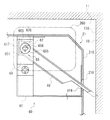
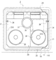
図1は、本発明の実施の形態に係る加熱調理器の一部分解の斜視図であり、図2は一部切欠の平面図である。
【0020】
この加熱調理器2は、上方に開口する矩形箱状の本体ケース21と、該本体ケース21の上端のケース開口部20を覆う天板24と、内部に加熱ヒータ(図示しない)を収容する矩形箱状のグリル32と、加熱調理器2の運転動作を制御する制御回路(図示しない)を収容する制御回路ケース34と、電磁誘導によって調理鍋やフライパン等を加熱させる加熱コイル30,30と、輻射熱によって調理鍋やフライパン等を加熱させる加熱ヒータ31とを備えている。
【0021】
以下、各部の詳細を説明する。
[本体ケース21について]
前記本体ケース21は、システムキッチンのカウンタトップ10に開設されたカウンタ孔11に落とし込み状態に装着されており、本体ケース21の上端のケース開口部20から張り出したフランジ22がカウンタ孔11の周縁に載置されている。
【0022】
尚、カウンタ孔11の内周は、本体ケース21の外周より若干大きく形成されており、本体ケース21の側壁210とカウンタ孔11の内周面110との間には、若干の間隙が形成される。
【0023】
本体ケース21の底部には、前記グリル32と前記制御回路ケース34とが並設されており、グリル32の上方および制御回路ケース34の上方には、前記加熱コイル30,30がそれぞれ配設されている。また、ケース開口部20の後部中央で且つグリル32の上方には、前記加熱ヒータ31が配設されている。
【0024】
さらに、制御回路ケース34の後部上面には、電源から高電圧が供給され、加熱コイル30,30や加熱ヒータ31等に電気を供給する電源回路35が配設されている。
【0025】
グリル32の後部には、天板24の裏面まで延びる排気ダクト320が連結されており、グリル32の内部の燃焼排気が該排気ダクト320を介して加熱調理器2の外部へ排出される。
【0026】
制御回路ケース34の後部には、天板24の裏面まで延びる吸気ダクト340が連結されており、制御回路を冷却するための外気が該吸気ダクト340を介して制御回路ケース34の内部へ吸入される。
また、ケース開口部20の後部両コーナーには、後述する位置決めユニット60が配設されている。
【0027】
[天板24について]
前記天板24は、天板24の周縁部がフランジ22の周縁部に嵌合した状態で、前記フランジ22の上部に載置されている。
天板24の後部中央には、前記排気ダクト320の先端の開口部が臨む排気ダクト用の天板開口部220と、前記吸気ダクト340の先端の開口部が臨む吸気ダクト用の天板開口部240とが並設されており、天板24の後部両コーナーには、本体ケース21の内部の空気を排出する換気用の天板開口部260,260が開設されている。
また、天板24の上面には、前記天板開口部220,240,260,260を覆う排気ガード29が載置されている。
【0028】
[位置決めユニット60について]
図3および図4に示すように、位置決めユニット60は、本体ケース21の内壁に固着される略L字状の支持フレーム61と、該支持フレーム61に鉛直姿勢で且つ回動自在に設けられる回動軸65と、該回動軸65に接続されるナット部材67と、先端が支持フレーム61に形成されたアーム支持部たる貫通孔616に支持され、後端が前記ナット部材67の上面に支持される揺動アーム66とを備えている。
【0029】
前記回動軸65は、支持フレーム61の上面と下面に形成された軸受け孔615,615に遊挿されており、回動軸65の上端に形成される操作部655が支持フレーム61の上面に当接した状態で保持されている。回動軸65の外周には、ナット部材67の内周に刻設される雌ねじ部671と螺合する雄ねじ部651が刻設されている。前記操作部655は、その上面にドライバー等の作業用工具を係合させる工具係合部656が形成されているとともに、回動軸65を抜け止め状態に保持するヘッドカバー69で覆われている。
【0030】
前記ナット部材67は、その一側面の平面部が支持フレーム61のガイド壁617に当接されている。即ち、回動軸65の回動に伴なって上下に摺動が可能な状態で回動軸65に螺合している。
【0031】
前記揺動アーム66は、金属板を断面コの字状に形成した細長板状体であり、その先端は尖っている。揺動アーム66の後端は、回動軸65が遊挿されるガイド孔665を備えており、回動軸65に沿って上下に移動が可能な状態でナット部材67の上面に支持されている。揺動アーム66の先端は、前記貫通孔616を介して側壁210に形成された側壁開口216に挿通されている。
【0032】
また、支持フレーム61に形成された前記貫通孔616は、カウンタ孔11の内周面110に対向し且つ回動軸65の上端寄りの高さ位置に設けられている。即ち、ナット部材67が回動軸65の下端側に位置するときには、揺動アーム66は、その後端が下がった傾斜姿勢で且つ先端が本体ケース21の内部にほぼ埋没した状態となり、ナット部材67が回動軸65の上端側に位置するときには、ほぼ水平姿勢で且つ先端が側壁開口部216から内周面110の方向へ突出した状態になるように設定されている。
【0033】
[本体ケース21の固定手順について]
次に、本体ケース21をカウンタ孔11に固定する際の作業手順を説明する(図4参照)。
まず、ナット部材67が回動軸65の下端側に位置する状態で、本体ケース21をカウンタ孔11に装着する。このとき、揺動アーム66は、その後端が下がった傾斜姿勢で保持され、その先端は本体ケース21の内部に埋没しているから、本体ケース21をカウンタ孔11に落とし込む際に、揺動アーム66の先端が邪魔にならない。
【0034】
そして、天板24に開設された天板開口部260から、操作部655に形成された工具係合部656に作業用工具を係合させ、操作部655を回動させる。このとき、ガイド壁617によって回動阻止状態で回動軸65に螺合されているナット部材67は、回動軸65に沿って上方へ移動し、揺動アーム66の後端を回動軸65に沿って上方へ押し上げる。
【0035】
ナット部材67が上方へ移動するに伴なって、揺動アーム66の後端は上方に押し上げられ、その先端が側壁210から外側へ突出してカウンタ孔11の内周面110に当接される。
【0036】
これにより、本体ケース21は、その左右の側壁210,210から突出する揺動アーム66,66によってカウンタ孔11の内周面110に位置決め固定され、加熱調理器2に対して水平方向に外力が作用した場合に、該加熱調理器2がカウンタトップ10に対して遊動するのを防止することができる。
【0037】
以上のように、上記加熱調理器2によれば、天板24を取り付けた状態のままで本体ケース21をカウンタ孔11に装着し、天板24に開設された天板開口部260,260から作業用工具で回動軸65を回動させれば、揺動アーム66が本体ケース21の側壁210,210から突出され、本体ケース21をカウンタトップ10に容易に位置決め固定することができるから、加熱調理器全体の施工作業工程が簡略化され、加熱調理器2をカウンタトップ10に固定する際の施工作業性が向上する。
【0038】
また、施工作業中に作業者が電源回路35に接触するおそれもないから、作業者の安全性が向上するとともに、本体ケース21の内部の電子回路を破損させるおそれもない。
【0039】
[第2実施形態]
次に、上記した本発明の第2実施形態を詳述する。
図5は、本発明の第2実施形態に係るビルトイン型加熱調理器に組み込まれる位置決めユニット80近傍の縦断面図である。
【0040】
位置決めユニット80は、本体ケース21の内壁に固着される支持フレーム81と、該支持フレーム81に鉛直姿勢で且つ回動自在に設けられる回動軸65と、該回動軸65の下端に固定状態で連結されるアーム受け87と、先端が支持フレーム81に形成された貫通孔816に支持され、後端が前記アーム受け87の上面に支持される揺動アーム66とを備えている。
【0041】
前記回動軸65は、支持フレーム81に接合された軸ナット部88に螺合されており、その上端には操作部655が形成されている。前記操作部655は、その上面に工具係合部656が形成されている。回動軸65の外周には、支持フレーム81に設けられた軸ナット部88の内周に刻設される雌ねじ部881と螺合する雄ねじ部651が刻設されている。即ち、回動軸65は、その回動に伴なって上下に移動が可能な状態で軸ナット部88に係合されている。尚、前記回動軸65が既述回動操作部材に対応する。
【0042】
前記揺動アーム66は、上記第1実施形態と同様の形状をしており、後端のガイド孔665に回動軸65が挿通されている。従って、揺動アーム66の後端は、回動軸65の上下への移動に伴なって上下に移動が可能な状態でアーム受け87の上面に支持されている。揺動アーム66の先端は、前記貫通孔816を介して側壁210に形成された側壁開口216に挿通されている。尚、前記揺動アーム66が既述位置決め部材に対応する。
【0043】
また、支持フレーム81に形成された前記貫通孔816は、カウンタ孔11の内周面110に対向し且つ軸ナット部88と略同一の高さに設けられている。即ち、回動軸65がその移動可能な範囲において下側に位置するときには、揺動アーム66は、その後端が下がった傾斜姿勢で且つ先端が本体ケース21の内部にほぼ埋没した状態となり、回動軸65がその移動可能な範囲において上側に位置するときには、ほぼ水平姿勢で且つ先端が側壁開口部216から内周面110の方向へ突出した状態になるように設定されている。
【0044】
尚、回動軸65の外周に刻設された雄ねじ部651と、回動軸65を上下に摺動が可能な状態でその雄ねじ部651と螺合する軸ナット部88と、揺動アーム66の後端を上下に移動させるアーム支持部87とを備えた機構部が、既述伝動機構に対応する。
【0045】
次に、本体ケース21をカウンタ孔11に固定する際の作業手順を説明する。
まず、回動軸65がその移動可能な範囲において下側に位置する状態で、本体ケース21をカウンタ孔11に装着する。このとき、揺動アーム66の先端は、上記第1実施形態と同様に、本体ケース21の内部に埋没しているから、本体ケース21をカウンタ孔11に落とし込む際に、揺動アーム66の先端が邪魔にならない。
【0046】
そして、天板24に開設された天板開口部260から作業用工具によって操作部655を回動させると、回動軸65がその上方へ移動し、アーム受け87に当接される揺動アーム66の後端を回動軸65に沿って上方へ押し上げる。
このとき、揺動アーム66の先端は、上記第1実施形態と同様に、側壁210から外側へ突出してカウンタ孔11の内周面110に当接される。
【0047】
これにより、本体ケース21は揺動アーム66,66によってカウンタ孔11の内周面110に位置決め固定され、加熱調理器2に対して水平方向に外力が作用した場合に、該加熱調理器2がカウンタトップ10に対して遊動するのを防止することができる。
【0048】
[その他]
▲1▼.前記回動軸65は、支持フレーム61(第2実施形態においては「支持フレーム81」)に鉛直姿勢で支持されているが、天板開口部260から操作部655を回動させることが可能であれば、支持フレーム61(第2実施形態においては「支持フレーム81」)に傾斜姿勢で支持されたものであっても良い。
【0049】
▲2▼.前記操作部655は、工具係合部656を有し、ドライバー等の作業用工具によって回動させるものであるが、作業者が操作部655を直接回動させることが可能なつまみ部を形成したものであっても良い。
【0050】
▲3▼.前記揺動アーム66は、その後端に形成されるガイド孔665に回動軸65を挿通させることによって上下方向への揺動が可能な構成になっているが、ナット部材67(第2実施形態においては「アーム受け87」)に揺動アーム66の後端を上下方向への揺動が可能な状態で連結したものであっても良い。
【0051】
▲4▼.揺動アーム66の先端は、ナット部材67が回動軸65の下端側に位置するとき(第2実施形態においては「回動軸65がその移動可能な範囲において下側に位置するとき」)には、本体ケース21の内部にほぼ埋没した状態になるように設定されているが、本体ケース21をカウンタ孔11に落とし込む際に邪魔にならなければ、側壁210から若干突出してても良い。
【0052】
▲5▼.揺動アーム66の先端は、支持フレーム61(第2実施形態においては「支持フレーム81」)に形成された貫通孔616(第2実施形態においては「貫通孔816」)に支持されているが、側壁開口216に支持されるものであっても良い。この場合、第1実施形態において、側壁開口216が既述のアーム支持部に対応する。
【0053】
▲6▼.既述の位置決め部材は、ウォームを備え且つ軸線方向への摺動が可能な摺動軸であり、既述の回動操作部材は、前記ウォームと連結する歯車を備え且つ鉛直姿勢に軸支される回動軸であり、既述の伝動機構は、前記ウォームと前記歯車とを備えたものであっても良い。
【図面の簡単な説明】
【図1】本発明の実施の形態に係るビルトイン型加熱調理器の一部分解の斜視図
【図2】本発明の実施の形態に係るビルトイン型加熱調理器の一部切欠の平面図
【図3】本発明の実施の形態に係るビルトイン型加熱調理器に組み込まれる位置決めユニット近傍の平面図
【図4】本発明の実施の形態に係るビルトイン型加熱調理器に組み込まれる位置決めユニット近傍の縦断面図
【図5】第2実施形態に係るビルトイン型加熱調理器に組み込まれる位置決めユニット近傍の説明図
【図6】従来例の説明図
【符号の説明】
2・・・加熱調理器
10・・・カウンタトップ
11・・・カウンタ孔
20・・・ケース開口部
21・・・本体ケース
24・・・天板
65・・・回動軸
66・・・揺動アーム
67・・・ナット部材
110・・・内周面
210・・・側壁
260・・・天板開口部
616・・・貫通孔
655・・・操作部[0001]
TECHNICAL FIELD OF THE INVENTION
TECHNICAL FIELD The present invention relates to a heating cooker of a type that is mounted in a counter hole formed in a countertop of a system kitchen while being dropped, that is, a built-in heating cooker.
[0002]
[Prior art]
The side wall of the main body case of the built-in type cooking device and the inner peripheral surface of the counter hole in which the main body case is mounted in a dropped state are provided with a slight gap from the viewpoint of construction workability. On the other hand, when an external force acts in the horizontal direction, there is a problem that the heating cooker body slightly moves with respect to the counter top. In order to prevent the play, there is known a device in which a main body case and a countertop are connected and fixed by a fixing bracket (for example, see Patent Document 1).
[0003]
Further, as shown in FIG. 6, there is a type in which the side wall of the main body case and the counter hole are fixed with fixing screws.
FIG. 6 is a partially cutaway plan view of a conventional built-in heating cooker in which a side wall of a main body case and a counter hole are fixed with fixing screws.
[0004]
A
[0005]
A
A
[0006]
Further, on the upper surface of the
[0007]
Fixing
Thereby, even when an external force acts on the
[0008]
[Patent Document 1]
JP-A-7-269883 (pages 1-8, FIG. 1)
[0009]
[Problems to be solved by the invention]
However, in the above-mentioned conventional built-in type cooking device, the fastening work of the
[0010]
In addition, the work of tightening the
[0011]
The present invention has been made in view of the above points,
"The system kitchen includes a main body case which is mounted in a counter hole formed in a counter top of the counter top, and a top plate which covers a case opening at an upper end of the main body case. Built-in type heating cooker with a top plate opening for communicating the outside with the outside of the product, '' improves the workability and safety of the operator when fixing the main body case to the countertop. It is an object to provide a cooker.
[0012]
[Means for Solving the Problems]
[1]
Technical means of the present invention for solving the above problems,
"A rotation operation member having an operation portion rotatable from above through the top plate opening at an upper end, and a rotation operation member penetrating a side wall of the main body case and abutting against an inner peripheral surface of the counter hole. A positioning member capable of moving away from each other, and a transmission mechanism for interlocking the rotation operation member and the positioning member,
The transmission mechanism has a function of converting the turning operation of the turning operation member into the abutting and separating operations of the positioning member. "
According to the above technical means, if the rotating operation member is rotated from above through the top plate opening formed in the top plate, the positioning member interlocked by the transmission mechanism is moved relative to the inner peripheral surface of the counter hole. The main body case can be fixed to the counter hole while the case opening of the main body case is covered with the top plate.
[0013]
[2]
In the
"The positioning member is a swing arm which is supported by a fixed arm support portion so as to be vertically swingable and whose tip faces the inner peripheral surface of the counter hole,
The rotating operation member is a rotating shaft disposed in a vertical posture below the top plate opening,
The transmission mechanism includes a male screw portion engraved on the outer periphery of the rotation shaft, and a screw screwed to the male screw portion, and moves the rear end of the swing arm up and down with rotation of the rotation shaft. And a nut member ”.
In this device, if the operation unit is rotated from above the top plate opening, the rear end portion of the swing arm moves up and down with the vertical movement of the nut member screwed into the male screw portion of the rotation shaft. , The swinging arm moves up and down toward the inner peripheral surface of the counter hole while swinging up and down about the arm support portion. That is, the tip of the swing arm swings in a direction in which it comes into contact with and separates from the inner peripheral surface of the counter hole. Thereby, the main body case can be fixed to the counter hole.
[0014]
[3]
In the
If the "operation portion is a tool engagement portion for engaging a work tool", the work tool is engaged with the tool engagement portion at the upper end of the rotating shaft from the top plate opening. Therefore, since the rotating shaft can be rotated, workability is better than that in which the knob formed at the upper end of the rotating shaft is directly rotated by hand.
[0015]
【The invention's effect】
The present invention has the following specific effects because of the above configuration.
Since the positioning operation of fixing the main body case to the counter hole can be performed while the case opening of the main body case is covered with the top plate, the construction work process of the entire cooking device is simplified, The workability when positioning and fixing the countertop to the countertop is improved.
[0016]
In addition, by performing the construction work from above with the top plate attached, there is no risk of the worker coming into contact with the power circuit during the construction work. There is no risk of damaging the electronic circuit.
[0017]
In the item (2), if the operation unit is rotated from above the top plate opening, the swinging arm swings up and down around the arm support portion and projects toward the inner peripheral surface of the counter hole and Since the retracting operation is performed, the range in which the swing arm protrudes and retracts can be set long. That is, the tip of the swing arm can be brought into contact with the inner peripheral surface of the counter hole with a small amount of rotation, so that the workability is good.
[0018]
In the case of item 3, if the rotating shaft is rotated by the work tool from above the top plate opening, the main body case can be easily fixed to the countertop, so that the workability in construction is further improved.
[0019]
BEST MODE FOR CARRYING OUT THE INVENTION
Next, the above-described embodiment of the present invention will be described in detail with reference to the drawings.
FIG. 1 is a partially exploded perspective view of a cooking device according to an embodiment of the present invention, and FIG. 2 is a partially cutaway plan view.
[0020]
The
[0021]
Hereinafter, details of each unit will be described.
[About body case 21]
The
[0022]
Note that the inner periphery of the
[0023]
The
[0024]
Further, on the rear upper surface of the
[0025]
An
[0026]
An
Further, a
[0027]
[About top plate 24]
The
At the rear center of the
An
[0028]
[About positioning unit 60]
As shown in FIG. 3 and FIG. 4, the
[0029]
The
[0030]
One side surface of the
[0031]
The
[0032]
Further, the through
[0033]
[Procedure for fixing body case 21]
Next, an operation procedure for fixing the
First, the
[0034]
Then, the work tool is engaged with the
[0035]
As the
[0036]
Thereby, the
[0037]
As described above, according to the
[0038]
In addition, since there is no possibility that the worker comes into contact with the
[0039]
[Second embodiment]
Next, the above-described second embodiment of the present invention will be described in detail.
FIG. 5 is a longitudinal sectional view near the
[0040]
The
[0041]
The
[0042]
The
[0043]
In addition, the through
[0044]
Note that a
[0045]
Next, an operation procedure for fixing the
First, the
[0046]
When the
At this time, the tip of the
[0047]
Thereby, the
[0048]
[Others]
▲ 1 ▼. The
[0049]
▲ 2 ▼. The
[0050]
(3). The
[0051]
▲ 4 ▼. The tip of the
[0052]
▲ 5 ▼. The tip of the
[0053]
▲ 6 ▼. The above-mentioned positioning member is a sliding shaft having a worm and capable of sliding in the axial direction, and the above-mentioned turning operation member is provided with a gear connected to the worm and is pivotally supported in a vertical posture. The transmission mechanism described above may include the worm and the gear.
[Brief description of the drawings]
1 is a partially exploded perspective view of a built-in heating cooker according to an embodiment of the present invention; FIG. 2 is a plan view of a partially cutaway of a built-in heating cooker according to an embodiment of the present invention; FIG. 4 is a plan view showing the vicinity of a positioning unit incorporated in the built-in type cooking device according to the embodiment of the present invention; FIG. FIG. 5 is an explanatory view showing the vicinity of a positioning unit incorporated in a built-in heating cooker according to a second embodiment. FIG. 6 is an explanatory view of a conventional example.
2 ...
Claims (3)
前記天板開口部を介して上方から回動が可能な操作部を上端に有する回動操作部材と、前記本体ケースの側壁を貫通し且つ前記カウンタ孔の内周面に対して当接および離反する動作が可能な位置決め部材と、前記回動操作部材と前記位置決め部材とを連動させる伝動機構とを備え、
前記伝動機構は、前記回動操作部材の前記回動の動作を前記位置決め部材の前記当接および離反する動作に変換する機能を具備する、ビルトイン型加熱調理器。The system kitchen includes a main body case which is mounted in a counter hole formed in a counter top opened in a counter top, and a top plate which covers a case opening at an upper end of the main body case. In the built-in type heating cooker where the top plate opening for communicating with the outside is opened,
A rotation operation member having an operation portion rotatable from above through the top plate opening at an upper end thereof, and a rotation operation member which penetrates a side wall of the main body case and abuts on and separates from an inner peripheral surface of the counter hole. A positioning member capable of performing an operation, and a transmission mechanism for interlocking the rotation operation member and the positioning member,
A built-in heating cooker, wherein the transmission mechanism has a function of converting the turning operation of the turning operation member into the abutting and separating operations of the positioning member.
前記位置決め部材は、固定のアーム支持部に上下揺動自在に支持され且つ先端が前記カウンタ孔の内周面に対向する揺動アームであり、
前記回動操作部材は、前記天板開口部の下方に鉛直姿勢で配設された回動軸であり、
前記伝動機構は、前記回動軸の外周に刻設された雄ねじ部と、前記雄ねじ部に螺合され且つ前記回動軸の回動に伴って前記揺動アームの後端を上下に移動させるナット部材とを備えた、ビルトイン型加熱調理器。The built-in type cooking device according to claim 1,
The positioning member is a swing arm that is supported by a fixed arm support portion so as to be able to swing up and down and whose tip faces the inner peripheral surface of the counter hole.
The rotating operation member is a rotating shaft disposed in a vertical posture below the top plate opening,
The transmission mechanism includes a male screw portion engraved on the outer periphery of the rotation shaft, and a screw screwed to the male screw portion, and moves the rear end of the swing arm up and down with rotation of the rotation shaft. A built-in heating cooker comprising a nut member.
前記操作部は、作業用工具を係合させるための工具係合部である、ビルトイン型加熱調理器。The built-in heating cooker according to claim 2,
The operating unit is a built-in type heating cooker, which is a tool engaging unit for engaging a work tool.
Priority Applications (1)
| Application Number | Priority Date | Filing Date | Title |
|---|---|---|---|
| JP2003102992A JP4188742B2 (en) | 2003-04-07 | 2003-04-07 | Built-in cooker |
Applications Claiming Priority (1)
| Application Number | Priority Date | Filing Date | Title |
|---|---|---|---|
| JP2003102992A JP4188742B2 (en) | 2003-04-07 | 2003-04-07 | Built-in cooker |
Publications (2)
| Publication Number | Publication Date |
|---|---|
| JP2004309014A true JP2004309014A (en) | 2004-11-04 |
| JP4188742B2 JP4188742B2 (en) | 2008-11-26 |
Family
ID=33466273
Family Applications (1)
| Application Number | Title | Priority Date | Filing Date |
|---|---|---|---|
| JP2003102992A Expired - Fee Related JP4188742B2 (en) | 2003-04-07 | 2003-04-07 | Built-in cooker |
Country Status (1)
| Country | Link |
|---|---|
| JP (1) | JP4188742B2 (en) |
Cited By (6)
| Publication number | Priority date | Publication date | Assignee | Title |
|---|---|---|---|---|
| JP2008298304A (en) * | 2007-05-29 | 2008-12-11 | Panasonic Corp | Heating cooker |
| JP2009036383A (en) * | 2007-07-31 | 2009-02-19 | Mitsubishi Electric Corp | Build-in type heating cooker |
| JP2011094860A (en) * | 2009-10-29 | 2011-05-12 | Mitsubishi Electric Corp | Built-in type cooker |
| JP2012097973A (en) * | 2010-11-02 | 2012-05-24 | Osaka Gas Co Ltd | Built-in gas stove |
| JP2016118324A (en) * | 2014-12-19 | 2016-06-30 | 三菱電機株式会社 | Heating cooker |
| JP2019074257A (en) * | 2017-10-17 | 2019-05-16 | リンナイ株式会社 | Cooking unit |
-
2003
- 2003-04-07 JP JP2003102992A patent/JP4188742B2/en not_active Expired - Fee Related
Cited By (7)
| Publication number | Priority date | Publication date | Assignee | Title |
|---|---|---|---|---|
| JP2008298304A (en) * | 2007-05-29 | 2008-12-11 | Panasonic Corp | Heating cooker |
| JP2009036383A (en) * | 2007-07-31 | 2009-02-19 | Mitsubishi Electric Corp | Build-in type heating cooker |
| JP2011094860A (en) * | 2009-10-29 | 2011-05-12 | Mitsubishi Electric Corp | Built-in type cooker |
| JP2012097973A (en) * | 2010-11-02 | 2012-05-24 | Osaka Gas Co Ltd | Built-in gas stove |
| JP2016118324A (en) * | 2014-12-19 | 2016-06-30 | 三菱電機株式会社 | Heating cooker |
| JP2019074257A (en) * | 2017-10-17 | 2019-05-16 | リンナイ株式会社 | Cooking unit |
| JP6995558B2 (en) | 2017-10-17 | 2022-01-14 | リンナイ株式会社 | Cooking equipment |
Also Published As
| Publication number | Publication date |
|---|---|
| JP4188742B2 (en) | 2008-11-26 |
Similar Documents
| Publication | Publication Date | Title |
|---|---|---|
| EP1927811A1 (en) | An equipped kitchen element having a hood and tiltable cooking range | |
| JP4189237B2 (en) | kitchenware | |
| JP2004309014A (en) | Built-in cooker | |
| JP4522903B2 (en) | Built-in cooking device | |
| JPH0335584B2 (en) | ||
| US6843245B2 (en) | High-level built-in oven unit | |
| CN105485735A (en) | Combined cooking range | |
| JP2007078248A (en) | Floor placement type cooker | |
| JP7051428B2 (en) | Cooker | |
| JP2003257289A (en) | Switch device of heating cooker | |
| JPH1057260A (en) | Exhauster | |
| JP5490747B2 (en) | Induction heating cooker | |
| JP2009036383A (en) | Build-in type heating cooker | |
| JP3079731U (en) | Cover device for gas range | |
| JP2003083548A (en) | Heating cooking apparatus | |
| JPH0737853B2 (en) | Range food | |
| KR20060104278A (en) | Oven range with sliding type backgard | |
| JP2009055854A (en) | Roasting apparatus | |
| JP2000161679A (en) | Heating cooker | |
| JP6917733B2 (en) | Cooker | |
| JPH0968315A (en) | Electronic oven range | |
| JPH089531Y2 (en) | Cooking equipment | |
| JP2565895Y2 (en) | Cooker | |
| JP2594256Y2 (en) | Okonomiyaki machine | |
| JP2548913Y2 (en) | Range food |
Legal Events
| Date | Code | Title | Description |
|---|---|---|---|
| A621 | Written request for application examination |
Free format text: JAPANESE INTERMEDIATE CODE: A621 Effective date: 20060323 |
|
| A131 | Notification of reasons for refusal |
Free format text: JAPANESE INTERMEDIATE CODE: A131 Effective date: 20071127 |
|
| A521 | Request for written amendment filed |
Free format text: JAPANESE INTERMEDIATE CODE: A523 Effective date: 20080121 |
|
| A131 | Notification of reasons for refusal |
Free format text: JAPANESE INTERMEDIATE CODE: A131 Effective date: 20080311 |
|
| A521 | Request for written amendment filed |
Free format text: JAPANESE INTERMEDIATE CODE: A523 Effective date: 20080512 |
|
| TRDD | Decision of grant or rejection written | ||
| A01 | Written decision to grant a patent or to grant a registration (utility model) |
Free format text: JAPANESE INTERMEDIATE CODE: A01 Effective date: 20080909 |
|
| A01 | Written decision to grant a patent or to grant a registration (utility model) |
Free format text: JAPANESE INTERMEDIATE CODE: A01 |
|
| A61 | First payment of annual fees (during grant procedure) |
Free format text: JAPANESE INTERMEDIATE CODE: A61 Effective date: 20080911 |
|
| R150 | Certificate of patent or registration of utility model |
Ref document number: 4188742 Country of ref document: JP Free format text: JAPANESE INTERMEDIATE CODE: R150 Free format text: JAPANESE INTERMEDIATE CODE: R150 |
|
| FPAY | Renewal fee payment (event date is renewal date of database) |
Free format text: PAYMENT UNTIL: 20110919 Year of fee payment: 3 |
|
| FPAY | Renewal fee payment (event date is renewal date of database) |
Free format text: PAYMENT UNTIL: 20120919 Year of fee payment: 4 |
|
| R250 | Receipt of annual fees |
Free format text: JAPANESE INTERMEDIATE CODE: R250 |
|
| FPAY | Renewal fee payment (event date is renewal date of database) |
Free format text: PAYMENT UNTIL: 20120919 Year of fee payment: 4 |
|
| FPAY | Renewal fee payment (event date is renewal date of database) |
Free format text: PAYMENT UNTIL: 20130919 Year of fee payment: 5 |
|
| R250 | Receipt of annual fees |
Free format text: JAPANESE INTERMEDIATE CODE: R250 |
|
| R250 | Receipt of annual fees |
Free format text: JAPANESE INTERMEDIATE CODE: R250 |
|
| R250 | Receipt of annual fees |
Free format text: JAPANESE INTERMEDIATE CODE: R250 |
|
| R250 | Receipt of annual fees |
Free format text: JAPANESE INTERMEDIATE CODE: R250 |
|
| R250 | Receipt of annual fees |
Free format text: JAPANESE INTERMEDIATE CODE: R250 |
|
| R250 | Receipt of annual fees |
Free format text: JAPANESE INTERMEDIATE CODE: R250 |
|
| R250 | Receipt of annual fees |
Free format text: JAPANESE INTERMEDIATE CODE: R250 |
|
| R250 | Receipt of annual fees |
Free format text: JAPANESE INTERMEDIATE CODE: R250 |
|
| R250 | Receipt of annual fees |
Free format text: JAPANESE INTERMEDIATE CODE: R250 |
|
| R250 | Receipt of annual fees |
Free format text: JAPANESE INTERMEDIATE CODE: R250 |
|
| LAPS | Cancellation because of no payment of annual fees |