JP2004308574A - Abnormality detection device of exhaust gas sensor - Google Patents
Abnormality detection device of exhaust gas sensor Download PDFInfo
- Publication number
- JP2004308574A JP2004308574A JP2003104011A JP2003104011A JP2004308574A JP 2004308574 A JP2004308574 A JP 2004308574A JP 2003104011 A JP2003104011 A JP 2003104011A JP 2003104011 A JP2003104011 A JP 2003104011A JP 2004308574 A JP2004308574 A JP 2004308574A
- Authority
- JP
- Japan
- Prior art keywords
- fuel ratio
- exhaust gas
- air
- storage capacity
- oxygen storage
- Prior art date
- Legal status (The legal status is an assumption and is not a legal conclusion. Google has not performed a legal analysis and makes no representation as to the accuracy of the status listed.)
- Granted
Links
Images


Abstract
Description
【0001】
【発明の属する技術分野】
本発明は、排気ガスセンサの異常検出装置に係り、特に、内燃機関の排気通路に配置される触媒の下流に位置する排気ガスセンサの異常を検出するうえで好適な異常検出装置に関する。
【0002】
【従来の技術】
従来、例えば特開平9−4496号公報に開示されるように、内燃機関の排気通路に配置された触媒の下流に酸素センサ(以下、「下流酸素センサ」と称す)を備える構成が知られている。下流酸素センサは、触媒から流出してくる排気ガスがリッチであるかリーンであるかに応じた出力を発する。上記従来の装置は、そのセンサ出力を利用することで、高精度な空燃比制御を実現することができる。
【0003】
上記従来の装置において、所望の空燃比フィードバック制御を得るためには、下流酸素センサが排気ガスの空燃比変化に対して優れた応答性を示すことが必要である。このため、下流酸素センサの応答遅れは速やかに検出できることが望ましい。上記従来の装置は、このような要求に応えるべく、下流酸素センサの出力信号の微分値を演算し、その微分値に基づいて下流酸素センサが適正な応答性を示しているか否かを診断することとしている。このような診断手法によれば、下流酸素センサの応答性悪化に伴ってセンサ出力の変化傾向(反転時における立ち上がり或いは立ち下がりの傾き)が変化する場合には、その応答性の悪化を迅速に検知することができる。
【0004】
【特許文献1】
特開平9−4496号公報
【特許文献2】
特開平5−125978号公報
【特許文献3】
特開平5−5447号公報
【0005】
【発明が解決しようとする課題】
しかしながら、下流酸素センサの応答性の悪化は、センサ出力の立ち上がりの開始点、或いは立ち下がりの開始点が遅れるような態様で生ずることがある。つまり、下流酸素センサの応答性の悪化時には、センサ出力の立ち上がり或いは立ち下がりの傾きより、むしろ、センサ出力の反転開始時期に顕著な遅れが生ずることがある。
【0006】
既述した通り、上記従来の装置は、センサ出力の微分値に基づいて下流酸素センサの異常を検知する。従って、センサ出力の反転開始時期に顕著な遅れが生じても、その立ち上がりの傾き、或いは立ち下がりの傾きに顕著な変化が表れない場合は、下流酸素センサの応答遅れを検知することができない。
【0007】
本発明は、上記のような課題を解決するためになされたもので、触媒の下流に配置される排気ガスセンサの応答遅れを、センサ出力の傾きの変化に頼ることなく検知することのできる排気ガスセンサの異常検出装置を提供することを目的とする。
【0008】
【課題を解決するための手段】
第1の発明は、上記の目的を達成するため、内燃機関の排気通路に配置される触媒の下流に位置する排気ガスセンサの異常を検出するための装置であって、
前記触媒上流における排気空燃比を制御する排気空燃比制御手段と、
前記排気ガスセンサの出力がリッチ出力からリーン出力に変化するのを受けて前記触媒上流の排気空燃比をリーン空燃比からリッチ空燃比に変化させ、また、前記排気ガスセンサの出力がリーン出力からリッチ出力に変化するのを受けて前記触媒上流の排気空燃比をリッチ空燃比からリーン空燃比に変化させるアクティブ空燃比制御を実行するアクティブ空燃比制御手段と、
前記アクティブ空燃比制御の実行中に、前記排気ガスセンサの出力がリッチ出力またはリーン出力に維持される期間中、前記触媒に流入する排気ガス中の酸素過不足量を積算することで、当該触媒の酸素吸蔵容量を算出する酸素吸蔵容量算出手段と、
前記酸素吸蔵容量と、その酸素吸蔵容量が算出された際の吸入空気量との関係に基づいて、前記排気ガスセンサの異常を検出する異常検出手段と、
を備えることを特徴とする。
【0009】
また、第2の発明は、第1の発明において、前記異常検出手段は、
吸入空気量の異なる2つの領域でそれぞれ算出された酸素吸蔵容量と、前記2つの領域における吸入空気量とに基づいて、吸入空気量の変化に対する酸素吸蔵容量の変化率を求める変化率算出手段と、
前記変化率が判定値を超えている場合に前記排気ガスセンサの異常を判定する異常判定手段と、
を備えることを特徴とする。
【0010】
また、第3の発明は、第1の発明において、前記異常検出手段は、
第1の吸入空気量下で算出された酸素吸蔵容量と、第2の吸入空気量下で算出された酸素吸蔵容量との差を求める容量差算出手段と、
前記酸素吸蔵容量の差が判定値を超えている場合に前記排気ガスセンサの異常を判定する異常判定手段と、
を備えることを特徴とする。
【0011】
【発明の実施の形態】
以下、図面を参照してこの発明の実施の形態について説明する。尚、各図において共通する要素には、同一の符号を付して重複する説明を省略する。
【0012】
実施の形態1.
[システム構成の説明]
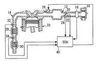
図1は、本発明の実施の形態1の構成を示す。図1に示す構成は、内燃機関10を備えている。内燃機関10には、吸気通路12および排気通路14が連通している。吸気通路12の端部にはエアフィルタ16が配置されている。エアフィルタ16の下流には、吸気通路12を流通する空気量、すなわち、吸入空気量Gaを検出するためのエアフロメータ18が配置されている。
【0013】
エアフロメータ18の下流には、スロットルバルブ20が設けられている。スロットルバルブ20の近傍には、スロットル開度TAを検出するスロットルセンサ22と、スロットルバルブ20が全閉となることでオンとなるアイドルスイッチ24とが配置されている。吸気通路12には、更に、内燃機関10の吸気ポートに燃料を噴射するための燃料噴射弁26が配置されている。
【0014】
排気通路14には、上流側触媒28と下流側触媒30とが直列に配置されている。これらの触媒は、内燃機関10が始動された後、所定の活性温度に達することにより排気ガスの浄化機能を発揮することができる。上流触媒28、および下流触媒30は、それぞれ酸素吸蔵容量(OSC:O2 Storage Capacitor)を有しており、その容量の範囲で酸素を吸蔵することができる。これらの触媒28,30は、排気ガス中にHCやCOなどの未燃成分が含まれている場合は、吸蔵している酸素を放出することでそれらの未燃成分を酸化し、また、排気ガス中に酸素やNOxなどが多く含まれている場合は、余剰酸素を吸蔵することで触媒内部の雰囲気を理論空燃比に保つことができる。上流触媒28および下流触媒30は、それぞれ上記の原理により排気ガスを浄化する。
【0015】
上流側触媒28の上流には、空燃比センサ32が配置されている。空燃比センサ32は、排気ガス中の酸素濃度に応じた出力を発するセンサである。排気ガス中の酸素濃度は、排気空燃比と相関を有している。このため、空燃比センサ32によれば、上流触媒28に流入する排気ガス、つまり、内燃機関10から排出されてきた直後の排気ガスの空燃比を検出することができる。
【0016】
上流触媒28の下流、つまり、下流触媒30の上流には、下流酸素センサ34が配置されている。下流酸素センサ34は、排気ガス中に酸素が存在するか否かに応じて出力を大きく変化させるセンサである。排気ガス中には、排気空燃比がリッチである場合には酸素は残留しない。一方、排気空燃比がリーンである場合は排気ガス中の酸素が残留する。このため、下流酸素センサ34によれば、上流触媒28から流出してくる排気ガスがリッチであるかリーンであるかを正確に検出することができる。
【0017】
図1に示すシステムは、ECU(Electronic Control Unit)40を備えている。ECU40には、上述した各種のセンサからセンサ出力が供給されている。また、ECU40は、それらのセンサ出力に基づいて内燃機関10に供給すべき燃料量を算出し、その燃料量が噴射されるように燃料噴射弁26を制御することができる。
【0018】
[酸素吸蔵容量OSCの算出手法]
本実施形態の装置は、上流触媒28の酸素吸蔵容量OSCを算出するため、および下流酸素センサ34の初動遅れ(応答遅れ)を検出するため、アクティブ空燃比制御を実行する。
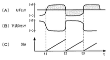
図2は、ECU40が実行するアクティブ空燃比制御の内容を説明するためのタイミングチャートである。より具体的には、図2(A)は、空燃比センサ32により検出される空燃比、つまり、上流触媒28に流入する排気ガスの空燃比(以下、「触媒前空燃比」と称す)の波形を示す。また、図2(B)は、下流酸素センサ34により検出される空燃比、つまり、下流酸素センサ34のセンサ出力波形を示す。更に、図2(C)は、アクティブ空燃比制御の実行中に算出される上流触媒28の酸素吸蔵量OSA(O2 Storage Amount)の変化を示す。
【0019】
アクティブ空燃比制御の実行中は、先ず、触媒前空燃比が所定のリッチ空燃比またはリーン空燃比に維持される。図2(A)は、時刻t1以後、時刻t2までの期間において、触媒前空燃比がリッチ空燃比に維持されている状態を示す。触媒前空燃比がリッチ空燃比に維持されると、上流触媒28は、吸蔵酸素を放出して排気ガス中の未燃成分(HC、CO)の酸化を図る。上流触媒28中に吸蔵酸素が残存している期間中は、その下流には理論空燃比に浄化された排気ガスが流出する。従って、その間、触媒後空燃比はほぼ理論空燃比に維持される。
【0020】
触媒前空燃比がリッチに維持された結果、上流触媒28中の吸蔵酸素が全て消費されると、その後、上流触媒28の下流には、未燃成分を含むリッチな排気ガスが流出し始める。上流触媒28の下流にリッチな排気ガスが流出し始めると、下流酸素センサ34のセンサ出力は、リーン出力からリッチ出力に変化する。図2(B)は、時刻t2において、上流触媒28中の吸蔵酸素が全て消費され、その後、下流酸素センサ34の出力がリーン出力からリッチ出力に反転した様子を示している。
【0021】
ECU40は、下流酸素センサ34の出力がリッチ出力に変化したと判断すると、その時点で、上流触媒28の吸蔵酸素が使い果たされたと判断する。そして、ECU40は、その後、触媒前空燃比がリーンに反転するように、吸入空気量Gaに対する燃料噴射量の割合を変化させる。その結果、時刻t2の後、図2(A)に示すように、触媒前空燃比はリッチからリーンに反転する。
【0022】
アクティブ空燃比制御の実行中は、以後、触媒前空燃比がリーンに維持される。触媒前空燃比がリーンに維持されている期間中、上流触媒28は、酸素吸蔵能力一杯に酸素を吸蔵するまで、酸素を吸蔵し続ける。そして、上流触媒28が排気ガス中の余剰酸素を吸蔵している間は、上流触媒28の下流に浄化された排気ガスが排出され、その後上流触媒28に酸素吸蔵能力一杯の酸素が吸蔵されると、その下流に酸素を含むリーンな排気ガスが流出し始める。
【0023】
図2に示す時刻t3は、上流触媒28の下流にリーンな排気ガスが流出し始めた時刻を示す。この時刻t3において、下流酸素センサ34の出力はリッチ出力からリーン出力に反転する。アクティブ空燃比制御の実行中において、ECU40は、このような下流酸素センサ34の出力反転を受けて、再び触媒前空燃比をリッチに反転させる。以後、アクティブ空燃比制御の実行が継続される限り、上述した処理、つまり、下流酸素センサ34の出力反転を受けて触媒前空燃比を強制的に反転させる処理が繰り返し実行される。
【0024】
アクティブ空燃比制御の実行中、下流酸素センサ34のセンサ出力は、既述した通り、上流触媒28内の酸素が全て消費された時点でリーン出力からリッチ出力に反転する。また、そのセンサ出力は、上流触媒28が酸素吸蔵容量OSC一杯に酸素を吸蔵した時点でリッチ出力からリーン出力に反転する。従って、下流酸素センサ34のセンサ出力がリーン出力からリッチ出力に反転した後(この反転を受けて触媒前空燃比は以後リーン空燃比とされる)、そのセンサ出力がリッチ出力からリーン出力に反転するまでの間、上流触媒28に流入した排気ガス中の酸素過剰量を積算すれば、上流触媒28の酸素吸蔵容量OSCを求めることができる。同様に、下流酸素センサ34のセンサ出力がリッチ出力からリーン出力に反転した後(この反転を受けて触媒前空燃比は以後リッチ空燃比とされる)、そのセンサ出力がリーン出力からリッチ出力に反転するまでの間、上流触媒28に流入した排気ガス中の酸素不足量を積算すれば、上流触媒28の酸素吸蔵容量OSCを求めることができる。
【0025】
触媒前空燃比A/Fがリーンである場合に、上流触媒28に流入する排気ガス中の酸素過剰量ΔOSAは、次式により求めることができる。
ΔOSA=(A/F−A/Fstoichi)×燃料噴射量×0.22 ・・・(1)
但し、A/Fstoichiは、理論空燃比であり、0.22は空気中の酸素の比率である。
一方、触媒前空燃比A/Fがリッチである場合に、上流触媒28に流入する排気ガス中の酸素不足量ΔOSAは、次式により求めることができる。
ΔOSA=(A/Fstoichi−A/F)×燃料噴射量×0.22 ・・・(2)
【0026】
従って、│A/F−A/Fstoichi│=ΔA/Fとすれば、触媒前空燃比A/Fがリッチである場合、およびリーンである場合を区別することなく、上流触媒28に流入する排気ガス中の酸素の過不足量ΔOSAを次式の通り表すことができる。
ΔOSA=ΔA/F×燃料噴射量×0.22 ・・・(3)
【0027】
ECU40は、下流酸素センサ34の出力が反転する毎に、酸素吸蔵量OSAをクリアし、以後、次式に示すように酸素過不足量ΔOSAの積算値を酸素吸蔵量OSAとして算出する。

【0028】
下流酸素センサ34の出力が反転するのは、上流触媒28内の酸素が全て放出された時点、および上流触媒28内に酸素が一杯に吸蔵された時点の何れかである。前者の場合は、その後、上流触媒28に酸素が一杯に吸蔵されて下流酸素センサ34の出力が再び反転するまで、酸素過剰量ΔOSAを積算することで上流触媒34の酸素吸蔵容量OSCを求めることができる。また、後者の場合も、その後、上流触媒34内の酸素が全て放出されて下流酸素センサ34の出力が再び反転するまで酸素不足量ΔOSAを積算することで上流触媒28の酸素吸蔵容量OSCを求めることができる。つまり、何れの場合において、下流酸素センサ34の出力が反転した時点では、その時点で算出されている酸素吸蔵量OSAは、上流触媒28の酸素吸蔵容量OSCとして認識することができる。そこで、ECU40は、上記の手法で酸素吸蔵量OSAを算出しつつ、下流酸素センサ34の出力が反転した際に、その時点における酸素吸蔵量OSAをクリアするに先だって、その値を上流触媒28の酸素吸蔵容量OSCとして認識することとしている。
【0029】
[下流酸素センサの初動遅れの影響]
次に、図3を参照して、上記の手法で算出される酸素吸蔵容量OSCと、下流酸素センサ34の初動遅れ(応答遅れ)との関係を説明する。
図3(A)は、アクティブ空燃比制御の実行中における下流酸素センサ34のセンサ出力の波形を示す。この図において、一点鎖線で示す波形は、正常時における下流酸素センサ34のセンサ出力であり、一方、実線で示す波形は、初動遅れの生じた下流酸素センサ34のセンサ出力である。また、図3(B)は、図3(A)に示すセンサ出力を受けて算出される酸素吸蔵量OSAの波形を示す。
【0030】
既述した通り、ECU40は、下流酸素センサ34の出力が反転する毎に、その時点で算出されている酸素吸蔵量OSA=ΣΔOSAを上流触媒28の酸素吸蔵容量OSCとして確定する。下流酸素センサ34の真の酸素吸蔵容量OSCがOSCaである場合、上流触媒28の下流には、ECU40により算出される酸素吸蔵量OSAがOSCaとなった時点で未浄化の排気ガスが流出し始める。下流酸素センサ34が正常な初動特性を示す場合は、その流出が開始された後、即座にセンサ出力が反転するため、酸素吸蔵容量OSCはOSCaとして確定される。
【0031】
これに対して、例えばセンサカバーの目詰まりなどの影響で、下流酸素センサ34に初動遅れの異常が生じている場合は、上流触媒28の下流に未浄化の排気ガスが流出し始めた後、即座にはセンサ出力が反転しない。この場合、上流触媒28の下流に未浄化の排気ガスが流出し始めた後、下流酸素センサ34の出力が反転するまでの初動遅れ時間Δtの間も酸素吸蔵量OSAの積算処理が継続される。その結果、下流酸素センサ34に初動遅れが生じている場合は、センサ出力が反転した時点で、真の酸素吸蔵容量OSCaに比して大きなOSCbが、その時点における酸素吸蔵容量OSCとして確定される事態が生ずる。
【0032】
ところで、下流酸素センサ34に初動遅れが生じている場合に確定される酸素吸蔵容量OSCbと、真の酸素吸蔵容量OSCaとの差は、センサ出力の初動遅れ期間をΔtとすると、次式のように表すことができる。 但し、次式においてΔOSCは、単位時間当たりの酸素過不足量であるものとする。
OSCb−OSCa=ΔOSC×Δt ・・・(5)
【0033】
酸素過不足量ΔOSAは、上記(1)式および(2)式に示すように燃料噴射量の関数である。燃料噴射量は、基本的には、内燃機関に供給される混合気が理論空燃比となるように決定されるものであり、吸入空気量Gaに比例すべきものである。このため、単位時間当たりの酸素過不足量ΔOSAは、吸入空気量Gaが多量であるほど大きな値となる。酸素過不足量ΔOSAがこのような特性を有していることから、下流酸素センサ34の初動遅れに起因する酸素吸蔵容量の誤差OSCb−OSCaは、吸入空気量Gaが多量であるほど大きなものとして表れる。従って、ECU40により算出される酸素吸蔵容量OSCは、下流酸素センサ34に初動遅れが生じている場合は、吸入空気量Gaが少ない場合に比して、吸入空気量Gaが多量である場合に大きな値として算出される。
【0034】
図4は、ECU40により算出される酸素吸蔵容量OSCと吸入空気量Gaとの関係を整理して表した図を示す。図4において、符号▲1▼を付して示す直線は、下流酸素センサ34に初動遅れが生じていない場合の関係を示す。また、符号▲2▼を付して示す直線は、下流酸素センサ34に比較的小さな初動遅れが生じた場合の関係を示す。そして、符号▲3▼を付して示す直線は、下流酸素センサ34に比較的大きな初動遅れが生じた場合の関係を示す。
【0035】
下流酸素センサ34に初動遅れが生じていない場合は、吸入空気量Gaの多少に関わらず、ECU40は、精度良く現実の値と合致する酸素吸蔵容量OSCを算出することができる。このため、直線▲1▼に示す通り、この場合はGaの値によらずOSCはほぼ一定の値となる。これに対して、下流酸素センサ34に初動遅れが生じている場合は、既述した理由により、吸入空気量Gaが多量であるほど酸素吸蔵容量OSCの算出値は大きな値となる。そして、この場合、直線▲2▼および▲3▼に示す通り、吸入空気量Gaに対する酸素吸蔵容量OSCの依存性は、初動遅れが大きいほど顕著なものとなる。
【0036】
酸素吸蔵容量OSCの算出値と吸入空気量Gaとが図4に示すような関係を示す場合、両者の依存性が顕著であるか否かに基づいて、下流酸素センサ34に初動遅れが生じているか否かを判断することが可能である。そこで、本実施形態では、吸入空気量Gaの変化に対する酸素吸蔵容量OSCの変化の割合を求め、その割合(変化率)に基づいて下流酸素センサ34の初動遅れの有無を判断することとした。
【0037】
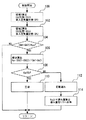
[具体的処理の説明]
図5は、上記の機能を実現するためにECU40が実行する制御ルーチンのフローチャートを示す。尚、図5に示すルーチンは、アクティブ空燃比制御の実行条件が成立していること(つまり、アクティブ空燃比制御が実行されていること)を条件に起動されるものとする。
【0038】
図5に示すルーチンでは、先ず、領域1での算出処理が実行される(ステップ100)。
本ステップ100では、具体的には、現在の状況下で酸素吸蔵容量OSCを算出し、その算出値を第1酸素吸蔵容量OSC1として記憶する処理、およびそのOSC1の算出時(下流酸素センサ34の出力反転時)における吸入空気量Gaを第1吸入空気量Ga1として記憶する処理が実行される。
【0039】
次に、領域2での算出処理が実行される(ステップ102)。
本ステップ102では、具体的には、現在の状況下で酸素吸蔵容量OSCを算出し、その算出値を第2酸素吸蔵容量OSC2として記憶する処理、およびそのOSC2の算出時(下流酸素センサ34の出力反転時)における吸入空気量Gaを第2吸入空気量Ga2として記憶する処理が実行される。
【0040】
図5に示すルーチンでは、次に、第1吸入空気量Ga1と第2吸入空気量Ga2との差│Ga1−Ga2│が所定の判定値Kgaより大きな値であるか否かが判別される(ステップ104)。
【0041】
その結果、│Ga1−Ga2│>Kgaが成立しないと判別された場合は、領域1における吸入空気量Ga1と領域2における吸入空気量Ga2との間に、酸素吸蔵容量OSCの吸入空気Ga依存性を判断するに足る十分な差が生じていなかったと判断される。この場合、以後、速やかに今回の処理サイクルが終了される。
【0042】
一方、上記ステップ104において、│Ga1−Ga2│>Kgaが成立すると判別された場合は、第1吸入空気量Ga1と第2吸入空気量Ga2との間に、OSCのGa依存性を判断するに足る差が生じていたと判断される。この場合、先ず、吸入空気量Gaの変化に対する酸素吸蔵容量OSCの変化の割合、つまり、Gaに対するOSCの変化率(変化の傾き)Kaが算出される(ステップ106)。
本ステップ106において、OSCの変化率Kaは、具体的には次式により算出される。
Ka=(OSC1−OSC2)/(Ga1−Ga2) ・・・(6)
【0043】
図5に示すルーチンでは、次に、上記ステップ106において算出された変化率Kaが、判定値Kbより小さいか否かが判別される(ステップ108)。
判定値Kbは、下流酸素センサ34に初動遅れが生じているか否かを判断するための判定値として予め定められた値である。従って、OSCの変化率Kaが判定値Kbを下回っていると判別された場合は、下流酸素センサ34に初動遅れは生じていないと判断することができる。一方、OSCの変化率Kaが判定値Kb以上であると判別された場合は、下流酸素センサ34に初動遅れが生じていると判断することができる。
【0044】
図5に示すルーチンでは、上記ステップ108において、Ka<Kbが成立すると判別された場合、以後、下流酸素センサ34が正常である旨の判断がなされた後(ステップ110)、今回の処理サイクルが終了される。
一方、Ka<Kbが成立しないと判別された場合は、先ず、下流酸素センサ34に初動遅れが生じているとの判断がなされる(ステップ112)。
そして、この場合は、判定値Kaより初動遅れの量が推定され、その遅れ量を空燃比フィードバック制御に反映させるための処理が実行された後(ステップ114)、今回の処理サイクルが終了される。
【0045】
上記ステップ114では、具体的には、初動遅れが大きいほど、下流酸素センサ34のセンサ出力を空燃比フィードバック制御に反映させる際の制御ゲインを小さくさせる等の処理が行われる。このような処理によれば、空燃比フィードバック制御に対する下流酸素センサ34の初動遅れの影響を小さくすることができ、初動遅れに起因する制御精度の悪化を抑制することができる。
【0046】
以上説明した通り、図5に示すルーチンによれば、吸入空気量Gaの変化に対して、ECU40により算出される酸素吸蔵容量OSCが判定値Kb以上の変化率Kaを示すか否かに基づいて、下流酸素センサ34の初動遅れの有無を判断することができる。このような手法によれば、下流酸素センサ34の初動遅れが、センサ出力の立ち上がりが緩やかになるような形態で表れる場合の他、その立ち上がりの時期のみが遅れるような形態で表れる場合にも、初動遅れの発生を検知することができる。このため、本実施形態の装置によれば、下流酸素センサ34の初動遅れを精度良く迅速に検知することができる。
【0047】
ところで、上述した実施の形態1においては、領域1や領域2において吸入空気量Gaがどのような値を採るかは成り行きに任せ、第1吸入空気量Ga1と第2吸入空気量Ga2との間に大きな差が存在する場合にのみ判定処理を進めることとしているが、その判定の手法はこれに限定されるものではない。すなわち、吸入空気量Gaが既定の第1吸入空気量Ga1となったときに領域1の算出処理を行い、また、吸入空気量Gaが既定の第2吸入空気量Ga2(Ga1とは大きく異なる値)となったときに領域2の算出処理を行うこととし、両者の算出後には常に判定処理を進めることとしてもよい。更に、この場合には、Ga1とGa2との差が一定となるため、酸素吸蔵容量OSCの変化率Kaに代えて、第1酸素吸蔵容量OSC1と第2酸素吸蔵容量OSC2との差│Ga1−Ga2│を、初動遅れの有無を判断するためのパラメータとして用いることとしてもよい。
【0048】
また、上述した実施の形態1においては、領域1および領域2において、第1または第2酸素吸蔵容量OSC1、OSC2の算出時における吸入空気量Gaが第1または第2吸入空気量Ga1、Ga2として記録されている。酸素吸蔵容量OSCの算出値に生ずる誤差の大きさは、既述した通り、初動遅れの間に発生した吸入空気量Gaの関数である。実施の形態1では、上記の第1または第2吸入空気量Ga1、Ga2を、初動遅れの間に発生した吸入空気量Gaの代表値として用いたものである。しかしながら、初動遅れの有無を判定するために用いるべき吸入空気量Gaは、そのような第1または第2吸入空気量Ga1、Ga2に限定されるものではなく、例えば、第1吸入空気量Ga1の算出期間における吸入空気量Gaの平均値、或いは、第2吸入空気量Ga2の算出期間における吸入空気量Gaの平均値などを第1または第2吸入空気量Ga1、Ga2として上記判定を行うこととしてもよい。
【0049】
尚、上述した実施の形態1においては、上流触媒28が前記第1の発明における「触媒」に相当している。また、ECU40が、上流触媒28の上流における排気空燃比を制御すべく燃料噴射量を制御することにより前記第1の発明における「排気空燃比制御手段」が、アクティブ空燃比制御を実行することにより前記第1の発明における「アクティブ空燃比制御手段」が、アクティブ空燃比制御の実行中に酸素吸蔵容量OSCを算出することにより前記第1の発明における「酸素吸蔵容量算出手段」が、上記ステップ106〜112の処理を実行することにより前記第1の発明における「異常検出手段」が、それぞれ実現されている。
【0050】
また、上述した実施の形態1においては、ECU40が、上記ステップ106の処理を実行することにより前記第2の発明における「変化率算出手段」が、上記ステップ108の処理を実行することにより前記第2の発明における「異常判定手段」が、それぞれ実現されている。
【0051】
また、上述した実施の形態1においては、ECU40に、既定の第1吸入空気量Ga1下で第1酸素吸蔵容量OSC1を算出させ、既定の第2吸入空気量Ga2下で第2酸素吸蔵容量OSC2を算出させ、それらの差を演算させることにより前記第3の発明における「容量差算出手段」を実現することができ、更に、その差が判定値を超えている場合に排気ガスセンサの初動遅れの発生を判定させることにより前記第3の発明における「異常判定手段」を実現することができる。
【0052】
【発明の効果】
この発明は以上説明したように構成されているので、以下に示すような効果を奏する。
第1の発明によれば、アクティブ空燃比制御の実行中に、触媒の酸素吸蔵容量を算出することができる。この酸素吸蔵容量は、吸入空気量が少ない場合には、排気ガスセンサの応答性が悪化しても、正常時の値と大きく異ならない一方、吸入空気量が多量である場合は、センサの応答性が悪化するに従い、正常時の値に比して顕著に大きな値となる。本発明によれば、酸素吸蔵容量と吸入空気量との関係が、排気ガスセンサの応答性の悪化を示唆しているかに基づいて、その応答性の悪化の有無を精度良く判断することができる。
【0053】
第2の発明によれば、吸入空気量の変化に対する酸素吸蔵容量の変化率が判定値を超えているか否かに基づいて、下流酸素センサの応答性が悪化しているか否かを精度良く判断することができる。
【0054】
第3の発明によれば、第1の吸入空気量下で算出された酸素吸蔵容量と、第2の吸入空気量下で算出された酸素吸蔵容量との差が判定値を超えているか否かに基づいて、下流酸素センサの応答性が悪化しているか否かを精度良く判断することができる。
【図面の簡単な説明】
【図1】本発明の実施の形態1の構成を説明するための図である。
【図2】本発明の実施の形態1の装置が実行するアクティブ空燃比制御の内容を説明するためのタイミングチャートである。
【図3】本発明の実施の形態1において算出される酸素吸蔵容量OSCと、下流酸素センサの初動遅れ(応答遅れ)との関係を説明するためのタイミングチャートである。
【図4】本実施形態の実施の形態1において算出される酸素吸蔵容量OSCと吸入空気量Gaとの関係を整理して表した図である。
【図5】本発明の実施の形態1において実行される制御ルーチンのフローチャートである。
【符号の説明】
10 内燃機関
12 吸気通路
14 排気通路
28 上流触媒
30 下流触媒
32 空燃比センサ
34 下流酸素センサ
Ga 吸入空気量
OSC 酸素吸蔵容量
OSA 酸素吸蔵量[0001]
TECHNICAL FIELD OF THE INVENTION
The present invention relates to an abnormality detection device for an exhaust gas sensor, and more particularly, to an abnormality detection device suitable for detecting an abnormality in an exhaust gas sensor located downstream of a catalyst disposed in an exhaust passage of an internal combustion engine.
[0002]
[Prior art]
Conventionally, as disclosed in, for example, Japanese Patent Application Laid-Open No. 9-4496, a configuration is known in which an oxygen sensor (hereinafter, referred to as “downstream oxygen sensor”) is provided downstream of a catalyst disposed in an exhaust passage of an internal combustion engine. I have. The downstream oxygen sensor outputs an output depending on whether the exhaust gas flowing out of the catalyst is rich or lean. The above-mentioned conventional device can realize highly accurate air-fuel ratio control by using the sensor output.
[0003]
In the above-described conventional apparatus, in order to obtain desired air-fuel ratio feedback control, it is necessary that the downstream oxygen sensor exhibit excellent responsiveness to changes in the air-fuel ratio of exhaust gas. Therefore, it is desirable that the response delay of the downstream oxygen sensor can be detected promptly. In order to respond to such a demand, the above-described conventional apparatus calculates a differential value of the output signal of the downstream oxygen sensor, and diagnoses whether or not the downstream oxygen sensor shows appropriate responsiveness based on the differential value. I'm supposed to. According to such a diagnostic method, when the tendency of the sensor output to change (the rising or falling slope at the time of inversion) changes with the deterioration of the response of the downstream oxygen sensor, the deterioration of the response is promptly reduced. Can be detected.
[0004]
[Patent Document 1]
JP-A-9-4496
[Patent Document 2]
JP-A-5-125978
[Patent Document 3]
JP-A-5-5447
[0005]
[Problems to be solved by the invention]
However, the deterioration of the response of the downstream oxygen sensor may occur in such a manner that the start point of the rise or the start point of the fall of the sensor output is delayed. That is, when the responsiveness of the downstream oxygen sensor is deteriorated, a remarkable delay may occur at the start time of the reversal of the sensor output, rather than the rising or falling slope of the sensor output.
[0006]
As described above, the conventional device detects an abnormality of the downstream oxygen sensor based on a differential value of the sensor output. Therefore, even if a remarkable delay occurs in the inversion start timing of the sensor output, if a remarkable change does not appear in the rising slope or the falling slope, the response delay of the downstream oxygen sensor cannot be detected.
[0007]
The present invention has been made in order to solve the above-described problems, and an exhaust gas sensor capable of detecting a response delay of an exhaust gas sensor disposed downstream of a catalyst without relying on a change in a sensor output gradient. An object of the present invention is to provide an abnormality detection device.
[0008]
[Means for Solving the Problems]
A first invention is a device for detecting an abnormality of an exhaust gas sensor located downstream of a catalyst disposed in an exhaust passage of an internal combustion engine, in order to achieve the above object,
Exhaust air-fuel ratio control means for controlling the exhaust air-fuel ratio upstream of the catalyst,
In response to the output of the exhaust gas sensor changing from the rich output to the lean output, the exhaust air-fuel ratio upstream of the catalyst is changed from the lean air-fuel ratio to the rich air-fuel ratio, and the output of the exhaust gas sensor is changed from the lean output to the rich output. Active air-fuel ratio control means for executing active air-fuel ratio control for changing the exhaust air-fuel ratio upstream of the catalyst from a rich air-fuel ratio to a lean air-fuel ratio in response to the change to
During the execution of the active air-fuel ratio control, during a period in which the output of the exhaust gas sensor is maintained at a rich output or a lean output, the amount of oxygen excess or deficiency in the exhaust gas flowing into the catalyst is integrated, so that the Oxygen storage capacity calculation means for calculating the oxygen storage capacity,
Abnormality detection means for detecting abnormality of the exhaust gas sensor based on a relationship between the oxygen storage capacity and the amount of intake air when the oxygen storage capacity is calculated;
It is characterized by having.
[0009]
In a second aspect based on the first aspect, the abnormality detecting means includes:
Change rate calculating means for calculating a change rate of the oxygen storage capacity with respect to a change in the intake air amount based on the oxygen storage capacity calculated in each of the two regions having different intake air amounts and the intake air amount in the two regions; ,
Abnormality determination means for determining abnormality of the exhaust gas sensor when the change rate exceeds a determination value,
It is characterized by having.
[0010]
In a third aspect based on the first aspect, the abnormality detecting means includes:
Capacity difference calculating means for calculating a difference between the oxygen storage capacity calculated under the first intake air amount and the oxygen storage capacity calculated under the second intake air amount;
Abnormality determination means for determining abnormality of the exhaust gas sensor when the difference in the oxygen storage capacity exceeds a determination value,
It is characterized by having.
[0011]
BEST MODE FOR CARRYING OUT THE INVENTION
Hereinafter, embodiments of the present invention will be described with reference to the drawings. Elements common to the drawings are denoted by the same reference numerals, and redundant description will be omitted.
[0012]
Embodiment 1 FIG.
[Description of system configuration]
FIG. 1 shows the configuration of the first embodiment of the present invention. The configuration shown in FIG. 1 includes an
[0013]
A
[0014]
In the
[0015]
An air-
[0016]
A
[0017]
The system shown in FIG. 1 includes an ECU (Electronic Control Unit) 40. The
[0018]
[Calculation method of oxygen storage capacity OSC]
The device according to the present embodiment executes active air-fuel ratio control in order to calculate the oxygen storage capacity OSC of the
FIG. 2 is a timing chart for explaining the contents of the active air-fuel ratio control executed by the
[0019]
During execution of the active air-fuel ratio control, first, the air-fuel ratio before the catalyst is maintained at a predetermined rich air-fuel ratio or lean air-fuel ratio. FIG. 2A shows a state where the pre-catalyst air-fuel ratio is maintained at the rich air-fuel ratio from time t1 to time t2. When the pre-catalyst air-fuel ratio is maintained at the rich air-fuel ratio, the
[0020]
As a result of maintaining the pre-catalyst air-fuel ratio to be rich, when all the stored oxygen in the
[0021]
When determining that the output of the
[0022]
During execution of the active air-fuel ratio control, the air-fuel ratio before the catalyst is maintained lean thereafter. During the period in which the pre-catalyst air-fuel ratio is maintained lean, the
[0023]
The time t3 shown in FIG. 2 indicates the time when the lean exhaust gas starts to flow downstream of the
[0024]
During execution of the active air-fuel ratio control, the sensor output of the
[0025]
When the air-fuel ratio A / F before the catalyst is lean, the excess oxygen amount ΔOSA in the exhaust gas flowing into the
ΔOSA = (A / FA−Fstoichi) × fuel injection amount × 0.22 (1)
Here, A / Fstoichi is the stoichiometric air-fuel ratio, and 0.22 is the ratio of oxygen in the air.
On the other hand, when the pre-catalyst air-fuel ratio A / F is rich, the oxygen deficiency ΔOSA in the exhaust gas flowing into the
ΔOSA = (A / Fstoichi-A / F) × fuel injection amount × 0.22 (2)
[0026]
Therefore, if | A / FA−F / stoichi | = ΔA / F, the exhaust gas flowing into the
ΔOSA = ΔA / F × fuel injection amount × 0.22 (3)
[0027]
The
[0028]
The output of the
[0029]
[Effect of delay in initial operation of downstream oxygen sensor]
Next, the relationship between the oxygen storage capacity OSC calculated by the above method and the initial operation delay (response delay) of the
FIG. 3A shows a waveform of a sensor output of the
[0030]
As described above, every time the output of the
[0031]
On the other hand, if the
[0032]
Incidentally, the difference between the oxygen storage capacity OSCb determined when the
OSCb−OSCa = ΔOSC × Δt (5)
[0033]
The oxygen excess / deficiency amount ΔOSA is a function of the fuel injection amount as shown in the above equations (1) and (2). The fuel injection amount is basically determined so that the air-fuel mixture supplied to the internal combustion engine has a stoichiometric air-fuel ratio, and should be proportional to the intake air amount Ga. For this reason, the oxygen excess / deficiency amount ΔOSA per unit time becomes larger as the intake air amount Ga increases. Since the oxygen excess / deficiency amount ΔOSA has such characteristics, the error OSCb−OSCa of the oxygen storage capacity caused by the delay of the initial operation of the
[0034]
FIG. 4 is a diagram illustrating a relationship between the oxygen storage capacity OSC calculated by the
[0035]
If the
[0036]
When the calculated value of the oxygen storage capacity OSC and the intake air amount Ga have the relationship shown in FIG. 4, the
[0037]
[Description of specific processing]
FIG. 5 shows a flowchart of a control routine executed by the
[0038]
In the routine shown in FIG. 5, first, a calculation process in region 1 is executed (step 100).
In this
[0039]
Next, a calculation process in region 2 is performed (step 102).
In this
[0040]
In the routine shown in FIG. 5, it is next determined whether or not the difference | Ga1-Ga2 | between the first intake air amount Ga1 and the second intake air amount Ga2 is larger than a predetermined determination value Kga ( Step 104).
[0041]
As a result, when it is determined that | Ga1−Ga2 |> Kga is not established, the dependence of the oxygen storage capacity OSC on the intake air Ga is set between the intake air amount Ga1 in the region 1 and the intake air amount Ga2 in the region 2. It is determined that there has not been a sufficient difference to determine. In this case, the current processing cycle is immediately terminated thereafter.
[0042]
On the other hand, if it is determined in
In this
Ka = (OSC1-OSC2) / (Ga1-Ga2) (6)
[0043]
In the routine shown in FIG. 5, next, it is determined whether or not the change rate Ka calculated in
The determination value Kb is a value determined in advance as a determination value for determining whether or not the initial movement delay has occurred in the
[0044]
In the routine shown in FIG. 5, if it is determined in
On the other hand, if it is determined that Ka <Kb is not established, it is first determined that the
In this case, the amount of the initial movement delay is estimated from the determination value Ka, and a process for reflecting the amount of delay in the air-fuel ratio feedback control is executed (step 114), and then the current processing cycle is ended. .
[0045]
In
[0046]
As described above, according to the routine shown in FIG. 5, based on whether or not the oxygen storage capacity OSC calculated by the
[0047]
In the first embodiment described above, what value the intake air amount Ga takes in the region 1 or the region 2 is left to the outcome, and the difference between the first intake air amount Ga1 and the second intake air amount Ga2 is determined. Is determined only when there is a large difference between the two, but the determination method is not limited to this. That is, when the intake air amount Ga becomes the predetermined first intake air amount Ga1, the calculation processing of the region 1 is performed, and the intake air amount Ga is set to a value that is significantly different from the predetermined second intake air amount Ga2 (Ga1). ), The calculation process of the area 2 may be performed, and the determination process may always be performed after the calculation of both. Further, in this case, since the difference between Ga1 and Ga2 is constant, the difference | Ga1− between the first oxygen storage capacity OSC1 and the second oxygen storage capacity OSC2 instead of the rate of change Ka of the oxygen storage capacity OSC. Ga2 | may be used as a parameter for judging the presence or absence of the initial movement delay.
[0048]
Further, in the above-described first embodiment, in region 1 and region 2, the intake air amount Ga at the time of calculating the first or second oxygen storage capacity OSC1, OSC2 is the first or second intake air amount Ga1, Ga2. Has been recorded. The magnitude of the error that occurs in the calculated value of the oxygen storage capacity OSC is a function of the intake air amount Ga generated during the initial operation delay, as described above. In the first embodiment, the above-mentioned first or second intake air amount Ga1, Ga2 is used as a representative value of the intake air amount Ga generated during the delay of the initial movement. However, the intake air amount Ga to be used to determine the presence or absence of the initial movement delay is not limited to such first or second intake air amounts Ga1 and Ga2. It is assumed that the above determination is made with the average value of the intake air amount Ga in the calculation period or the average value of the intake air amount Ga in the calculation period of the second intake air amount Ga2 as the first or second intake air amount Ga1, Ga2. Is also good.
[0049]
In the first embodiment, the
[0050]
In the first embodiment described above, the
[0051]
Further, in the above-described first embodiment, the
[0052]
【The invention's effect】
Since the present invention is configured as described above, it has the following effects.
According to the first aspect, the oxygen storage capacity of the catalyst can be calculated during execution of the active air-fuel ratio control. This oxygen storage capacity does not greatly differ from the normal value even if the response of the exhaust gas sensor is deteriorated when the intake air amount is small, while the response of the sensor is large when the intake air amount is large. As the value worsens, the value becomes significantly larger than the value in the normal state. According to the present invention, it is possible to accurately determine whether or not the responsiveness of the exhaust gas sensor has deteriorated based on whether the relationship between the oxygen storage capacity and the intake air amount indicates that the responsiveness of the exhaust gas sensor has deteriorated.
[0053]
According to the second aspect, it is accurately determined whether or not the responsiveness of the downstream oxygen sensor has deteriorated based on whether or not the rate of change of the oxygen storage capacity with respect to the change of the intake air amount exceeds the determination value. can do.
[0054]
According to the third invention, it is determined whether or not the difference between the oxygen storage capacity calculated under the first intake air amount and the oxygen storage capacity calculated under the second intake air amount exceeds the determination value. , It is possible to accurately determine whether or not the responsiveness of the downstream oxygen sensor has deteriorated.
[Brief description of the drawings]
FIG. 1 is a diagram for explaining a configuration of a first embodiment of the present invention.
FIG. 2 is a timing chart for explaining details of active air-fuel ratio control executed by the device according to the first embodiment of the present invention.
FIG. 3 is a timing chart for explaining a relationship between an oxygen storage capacity OSC calculated in the first embodiment of the present invention and an initial operation delay (response delay) of a downstream oxygen sensor.
FIG. 4 is a diagram summarizing the relationship between the oxygen storage capacity OSC calculated in the first embodiment of the present embodiment and the intake air amount Ga.
FIG. 5 is a flowchart of a control routine executed in the first embodiment of the present invention.
[Explanation of symbols]
10 Internal combustion engine
12 Intake passage
14 Exhaust passage
28 Upstream catalyst
30 Downstream catalyst
32 air-fuel ratio sensor
34 Downstream oxygen sensor
Ga intake air volume
OSC oxygen storage capacity
OSA Oxygen storage capacity
Claims (3)
前記触媒上流における排気空燃比を制御する排気空燃比制御手段と、
前記排気ガスセンサの出力がリッチ出力からリーン出力に変化するのを受けて前記触媒上流の排気空燃比をリーン空燃比からリッチ空燃比に変化させ、また、前記排気ガスセンサの出力がリーン出力からリッチ出力に変化するのを受けて前記触媒上流の排気空燃比をリッチ空燃比からリーン空燃比に変化させるアクティブ空燃比制御を実行するアクティブ空燃比制御手段と、
前記アクティブ空燃比制御の実行中に、前記排気ガスセンサの出力がリッチ出力またはリーン出力に維持される期間中、前記触媒に流入する排気ガス中の酸素過不足量を積算することで、当該触媒の酸素吸蔵容量を算出する酸素吸蔵容量算出手段と、
前記酸素吸蔵容量と、その酸素吸蔵容量が算出された際の吸入空気量との関係に基づいて、前記排気ガスセンサの異常を検出する異常検出手段と、
を備えることを特徴とする排気ガスセンサの異常検出装置。An apparatus for detecting an abnormality of an exhaust gas sensor located downstream of a catalyst disposed in an exhaust passage of an internal combustion engine,
Exhaust air-fuel ratio control means for controlling the exhaust air-fuel ratio upstream of the catalyst,
In response to the output of the exhaust gas sensor changing from the rich output to the lean output, the exhaust air-fuel ratio upstream of the catalyst is changed from the lean air-fuel ratio to the rich air-fuel ratio, and the output of the exhaust gas sensor is changed from the lean output to the rich output. Active air-fuel ratio control means for executing active air-fuel ratio control for changing the exhaust air-fuel ratio upstream of the catalyst from a rich air-fuel ratio to a lean air-fuel ratio in response to the change to
During the execution of the active air-fuel ratio control, during a period in which the output of the exhaust gas sensor is maintained at a rich output or a lean output, the amount of oxygen excess or deficiency in the exhaust gas flowing into the catalyst is integrated, so that the Oxygen storage capacity calculation means for calculating the oxygen storage capacity,
Abnormality detection means for detecting abnormality of the exhaust gas sensor based on a relationship between the oxygen storage capacity and the amount of intake air when the oxygen storage capacity is calculated;
An abnormality detection device for an exhaust gas sensor, comprising:
吸入空気量の異なる2つの領域でそれぞれ算出された酸素吸蔵容量と、前記2つの領域における吸入空気量とに基づいて、吸入空気量の変化に対する酸素吸蔵容量の変化率を求める変化率算出手段と、
前記変化率が判定値を超えている場合に前記排気ガスセンサの異常を判定する異常判定手段と、
を備えることを特徴とする請求項1記載の排気ガスセンサの異常検出装置。The abnormality detecting means includes:
Change rate calculating means for calculating a change rate of the oxygen storage capacity with respect to a change in the intake air amount based on the oxygen storage capacity calculated in each of the two regions having different intake air amounts and the intake air amount in the two regions; ,
Abnormality determination means for determining abnormality of the exhaust gas sensor when the change rate exceeds a determination value,
The exhaust gas sensor abnormality detection device according to claim 1, further comprising:
第1の吸入空気量下で算出された酸素吸蔵容量と、第2の吸入空気量下で算出された酸素吸蔵容量との差を求める容量差算出手段と、
前記酸素吸蔵容量の差が判定値を超えている場合に前記排気ガスセンサの異常を判定する異常判定手段と、
を備えることを特徴とする請求項1記載の排気ガスセンサの異常検出装置。The abnormality detecting means includes:
Capacity difference calculating means for calculating a difference between the oxygen storage capacity calculated under the first intake air amount and the oxygen storage capacity calculated under the second intake air amount;
Abnormality determination means for determining abnormality of the exhaust gas sensor when the difference in the oxygen storage capacity exceeds a determination value,
The exhaust gas sensor abnormality detection device according to claim 1, further comprising:
Priority Applications (1)
| Application Number | Priority Date | Filing Date | Title |
|---|---|---|---|
| JP2003104011A JP4366976B2 (en) | 2003-04-08 | 2003-04-08 | Exhaust gas sensor abnormality detection device |
Applications Claiming Priority (1)
| Application Number | Priority Date | Filing Date | Title |
|---|---|---|---|
| JP2003104011A JP4366976B2 (en) | 2003-04-08 | 2003-04-08 | Exhaust gas sensor abnormality detection device |
Publications (2)
| Publication Number | Publication Date |
|---|---|
| JP2004308574A true JP2004308574A (en) | 2004-11-04 |
| JP4366976B2 JP4366976B2 (en) | 2009-11-18 |
Family
ID=33466960
Family Applications (1)
| Application Number | Title | Priority Date | Filing Date |
|---|---|---|---|
| JP2003104011A Expired - Fee Related JP4366976B2 (en) | 2003-04-08 | 2003-04-08 | Exhaust gas sensor abnormality detection device |
Country Status (1)
| Country | Link |
|---|---|
| JP (1) | JP4366976B2 (en) |
Cited By (6)
| Publication number | Priority date | Publication date | Assignee | Title |
|---|---|---|---|---|
| JP2009063329A (en) * | 2007-09-04 | 2009-03-26 | Denso Corp | Deterioration simulator of gas sensor |
| JP2011001880A (en) * | 2009-06-18 | 2011-01-06 | Toyota Motor Corp | Abnormal condition detecting device for air-fuel ratio sensor |
| WO2015049726A1 (en) | 2013-10-01 | 2015-04-09 | トヨタ自動車株式会社 | Abnormality diagnosis system for air-fuel ratio sensor |
| JP2016223406A (en) * | 2015-06-03 | 2016-12-28 | 富士重工業株式会社 | Catalyst diagnosis device |
| US10156200B2 (en) | 2015-07-29 | 2018-12-18 | Toyota Jidosha Kabushiki Kaisha | Abnormality diagnosis system of downstream side air-fuel ratio sensor |
| US10316779B2 (en) | 2013-10-01 | 2019-06-11 | Toyota Jidosha Kabushiki Kaisha | Abnormality diagnosis system of air-fuel ratio sensor |
-
2003
- 2003-04-08 JP JP2003104011A patent/JP4366976B2/en not_active Expired - Fee Related
Cited By (9)
| Publication number | Priority date | Publication date | Assignee | Title |
|---|---|---|---|---|
| JP2009063329A (en) * | 2007-09-04 | 2009-03-26 | Denso Corp | Deterioration simulator of gas sensor |
| US7980121B2 (en) | 2007-09-04 | 2011-07-19 | Denso Corporation | Degradation simulator for gas sensor |
| JP2011001880A (en) * | 2009-06-18 | 2011-01-06 | Toyota Motor Corp | Abnormal condition detecting device for air-fuel ratio sensor |
| US8485167B2 (en) | 2009-06-18 | 2013-07-16 | Toyota Jidosha Kabushiki Kaisha | Abnormality detection apparatus and abnormality detection method for air/fuel ratio sensor |
| WO2015049726A1 (en) | 2013-10-01 | 2015-04-09 | トヨタ自動車株式会社 | Abnormality diagnosis system for air-fuel ratio sensor |
| US10316779B2 (en) | 2013-10-01 | 2019-06-11 | Toyota Jidosha Kabushiki Kaisha | Abnormality diagnosis system of air-fuel ratio sensor |
| US10365183B2 (en) | 2013-10-01 | 2019-07-30 | Toyota Jidosha Kabushiki Kaisha | Abnormality diagnosis system of air-fuel ratio sensor |
| JP2016223406A (en) * | 2015-06-03 | 2016-12-28 | 富士重工業株式会社 | Catalyst diagnosis device |
| US10156200B2 (en) | 2015-07-29 | 2018-12-18 | Toyota Jidosha Kabushiki Kaisha | Abnormality diagnosis system of downstream side air-fuel ratio sensor |
Also Published As
| Publication number | Publication date |
|---|---|
| JP4366976B2 (en) | 2009-11-18 |
Similar Documents
| Publication | Publication Date | Title |
|---|---|---|
| US8146346B2 (en) | NOx trapping catalytic converter diagnostic apparatus | |
| JP4042376B2 (en) | Catalyst deterioration detection device for internal combustion engine | |
| JP4497132B2 (en) | Catalyst degradation detector | |
| JP4305643B2 (en) | Exhaust gas purification device for internal combustion engine | |
| JP2004257324A (en) | Emission control device for internal combustion engine | |
| JP2008223611A (en) | Catalyst deterioration judging device | |
| US7513105B2 (en) | Exhaust gas purifying system and abnormality determining method therefor | |
| US10859018B1 (en) | Exhaust gas purification system using three-way catalyst and method of controlling the same | |
| JP3868693B2 (en) | Air-fuel ratio control device for internal combustion engine | |
| EP2052137B1 (en) | Catalyst monitoring system and method | |
| JP6611397B2 (en) | Catalyst diagnostic device | |
| JP2017025863A (en) | ABNORMALITY DIAGNOSIS DEVICE OF NOx OCCLUSION REDUCTION TYPE CATALYST | |
| US20040226282A1 (en) | Abnormality detecting system for oxygen sensor and abnormality detecting method | |
| US20060168943A1 (en) | Method for operating an internal combustion engine and device for implementing the method | |
| JP4237202B2 (en) | Air-fuel ratio feedback control device | |
| JP5515967B2 (en) | Diagnostic equipment | |
| WO2007138454A1 (en) | Exhaust purification device and method of internal combustion engine | |
| JP4366976B2 (en) | Exhaust gas sensor abnormality detection device | |
| KR100774718B1 (en) | Oxygen control method of catalytic converter for vehicle | |
| US10392986B2 (en) | Exhaust purification system, and control method for exhaust purification system | |
| US10677128B2 (en) | Exhaust purification system and catalyst regeneration method | |
| JP2008057486A (en) | Exhaust emission control device of internal combustion engine | |
| JP2006057461A (en) | Irregularity detection device | |
| JP2004232576A (en) | Exhaust emission control device for internal combustion engine | |
| JP2004285949A (en) | Failure detector for exhaust gas sensor |
Legal Events
| Date | Code | Title | Description |
|---|---|---|---|
| A621 | Written request for application examination |
Free format text: JAPANESE INTERMEDIATE CODE: A621 Effective date: 20060306 |
|
| A977 | Report on retrieval |
Effective date: 20080424 Free format text: JAPANESE INTERMEDIATE CODE: A971007 |
|
| A131 | Notification of reasons for refusal |
Free format text: JAPANESE INTERMEDIATE CODE: A131 Effective date: 20080507 |
|
| A521 | Written amendment |
Effective date: 20080704 Free format text: JAPANESE INTERMEDIATE CODE: A523 |
|
| A131 | Notification of reasons for refusal |
Effective date: 20081216 Free format text: JAPANESE INTERMEDIATE CODE: A131 |
|
| A521 | Written amendment |
Free format text: JAPANESE INTERMEDIATE CODE: A523 Effective date: 20090212 |
|
| TRDD | Decision of grant or rejection written | ||
| A01 | Written decision to grant a patent or to grant a registration (utility model) |
Free format text: JAPANESE INTERMEDIATE CODE: A01 Effective date: 20090804 |
|
| A01 | Written decision to grant a patent or to grant a registration (utility model) |
Free format text: JAPANESE INTERMEDIATE CODE: A01 |
|
| A61 | First payment of annual fees (during grant procedure) |
Effective date: 20090817 Free format text: JAPANESE INTERMEDIATE CODE: A61 |
|
| FPAY | Renewal fee payment (prs date is renewal date of database) |
Year of fee payment: 3 Free format text: PAYMENT UNTIL: 20120904 |
|
| FPAY | Renewal fee payment (prs date is renewal date of database) |
Year of fee payment: 4 Free format text: PAYMENT UNTIL: 20130904 |
|
| LAPS | Cancellation because of no payment of annual fees |