JP2004308452A - Computer device for engine control - Google Patents
Computer device for engine control Download PDFInfo
- Publication number
- JP2004308452A JP2004308452A JP2003099618A JP2003099618A JP2004308452A JP 2004308452 A JP2004308452 A JP 2004308452A JP 2003099618 A JP2003099618 A JP 2003099618A JP 2003099618 A JP2003099618 A JP 2003099618A JP 2004308452 A JP2004308452 A JP 2004308452A
- Authority
- JP
- Japan
- Prior art keywords
- control
- control unit
- engine
- control information
- sub
- Prior art date
- Legal status (The legal status is an assumption and is not a legal conclusion. Google has not performed a legal analysis and makes no representation as to the accuracy of the status listed.)
- Withdrawn
Links
Images
Classifications
-
- Y—GENERAL TAGGING OF NEW TECHNOLOGICAL DEVELOPMENTS; GENERAL TAGGING OF CROSS-SECTIONAL TECHNOLOGIES SPANNING OVER SEVERAL SECTIONS OF THE IPC; TECHNICAL SUBJECTS COVERED BY FORMER USPC CROSS-REFERENCE ART COLLECTIONS [XRACs] AND DIGESTS
- Y02—TECHNOLOGIES OR APPLICATIONS FOR MITIGATION OR ADAPTATION AGAINST CLIMATE CHANGE
- Y02T—CLIMATE CHANGE MITIGATION TECHNOLOGIES RELATED TO TRANSPORTATION
- Y02T10/00—Road transport of goods or passengers
- Y02T10/10—Internal combustion engine [ICE] based vehicles
- Y02T10/30—Use of alternative fuels, e.g. biofuels
Abstract
Description
【0001】
【発明の属する技術分野】
本発明は、自動車車両に搭載されて、エンジンの動作を制御するエンジン制御用コンピュータ装置に関する。
【0002】
【従来の技術】
従来から、自動車のエンジン、特にガソリンエンジンは、点火制御、アイドルスピードコントロール(以下、「ISC」と略称する)、および噴射制御などを、マイクロコンピュータを搭載するエンジン制御用コンピュータ装置によって行っている。エンジンの性能を充分に発揮させるためには、エンジン制御用コンピュータ装置も、制御対象となるエンジンに合わせて作成する必要がある。ただし、制御対象となる複数種類のエンジンが予め決っている場合は、プログラムの少なくとも一部や、制御データを複数種類用意して、エンジン制御用コンピュータ装置をその複数種類のエンジンで共通化することもある。
【0003】
自動車用のエンジンや、汎用エンジンには、アルコールを燃料として使用することも検討されている。内燃機関の点火時期の制御では、アルコール濃度毎に基本制御値を予め定めたマップを複数備えて、使用中のアルコール濃度に応じてマップの切換を行う(たとえば、特許文献1参照)。ガソリンとアルコールとを混合して燃料とするエンジンでは、複数のアルコール混合割合に対して最適なエンジン制御量をマップとして用意しておき、中間の混合割合に対しては重み付き補間計算を行って、エンジンの制御を行うようにしている(たとえば、特許文献2参照)。ガソリンとアルコール混合燃料とが選択的に使用される2サイクル機関では、ガソリンとアルコールとに適合する空燃比補正マップをそれぞれ記憶させておき、ガソリンに適合するマップを使用していて、燃焼圧力が基準燃焼圧力を超えると、アルコール混合燃料の使用と判断してマップを切換えるようにしている(たとえば、特許文献3参照)。
【0004】
ガス燃料と液体燃料とを使い分ける汎用エンジンでは、燃料供給制御装置に、液体燃料エンジン用、ガス燃料エンジン用および液体燃料とガス燃料とを切換えるエンジン用の3種のプログラムを備えておく(たとえば、特許文献4参照)。石油のような第1燃料の他に、LPG(液化石油ガス)などの第2の種類の燃料を使用して運転される内燃エンジンでは、第2の種類の燃料使用時に、第2制御装置による燃料供給量の制御を行い、第1制御装置との間でプロセスパラメータと運転パラメータ等の調整を行う(たとえば、特許文献5参照)。
【0005】
【特許文献1】
特公平7−13508号公報
【特許文献2】
特開平5−195838号公報
【特許文献3】
特開平6−66175号公報
【特許文献4】
特開2000−145488号公報
【特許文献5】
特表平9−505653号公報
【0006】
【発明が解決しようとする課題】
自動車のエンジンとして、ガソリンエンジンと他の燃料のエンジンとを使用する場合、特許文献4のように、それぞれのエンジンに合わせたプログラムをエンジン制御用コンピュータ装置に用意しておいて、切換えることが考えられる。しかしながら、燃料が異なると、たとえば燃料噴射用のアクチュエータなどが異なり、駆動用の出力回路などに要求される特性や仕様も異なってくる。このため、アクチュエータ駆動用の専用ユニットをサブ制御ユニットとして、全体の制御を行うメイン制御ユニットと別にして、アクチュエータ近傍にサブ制御ユニットを設置し、離れた位置に設置するメイン制御ユニットとは車載LAN(Local Area Network)などの通信路で接続し、データ通信でエンジン制御を行うような構成が考えられる。このような構成でも、メイン制御ユニットには、複数のプログラムを用意して、エンジンの種類に応じて切換えるようにする必要がある。
【0007】
使用するエンジンの種類数に対応してプログラムを用意しておくことは、プログラム開発の負担が大きい。また、基本的には同一のエンジンの燃料にガソリンと他の燃料とを使用することが判っていても、他の燃料についてはガソリンよりも開発が遅れるような場合もある。このような場合には、燃料に応じてメイン制御ユニットも専用にするか、メイン制御ユニットのプログラムや制御パラメータを後から設定や書換えが可能なようしておく必要がある。
【0008】
メイン制御ユニットをエンジンの種類に応じて専用化することは、生産管理が複雑になる。また、ガソリンエンジンに比較して、他の燃料のエンジンを搭載する車両は少量生産でもあるので、専用のメイン制御ユニットを開発することは、生産コストを上昇させてしまうことにもなる。メイン制御ユニットのプログラムや制御パラメータを後から設定や書換えが可能なようにしておくことは、設定や書換えを行うツールを導入する必要がある。そのようなツールを車両組立て工場等に導入して、生産ラインで使用することは、ツール自体の導入コストや、ツールの使用に必要な作業時間によるコストで、車両の生産コストが増加してしまう。
【0009】
本発明の目的は、エンジンの種類の変更など適合する制御を、専用化や、プログラムやデータを変更するツールの導入なしに可能にするエンジン制御用コンピュータ装置を提供することである。
【0010】
【課題を解決するための手段】
本発明は、車両に搭載され、エンジンの制御を行うエンジン制御用コンピュータ装置であって、
予め設定されるプログラムを実行して、エンジンを制御するメイン制御ユニットと、
メイン制御ユニットに対してデータ通信用の通信路を介して接続され、制御対象のエンジンの予め定める部分的な機能について、メイン制御ユニットのプログラムに付加する制御情報を有するサブ制御ユニットとを含み、
メイン制御ユニットは、
通信路を介してサブ制御ユニットから該制御情報を取得する制御情報取得手段と、
制御情報取得手段によって取得される制御情報を格納し、プログラムの実行中にプログラムから参照される制御情報格納手段とを備えることを特徴とするエンジン制御用コンピュータ装置である。
【0011】
本発明に従えば、エンジン制御用コンピュータ装置は、車両に搭載され、エンジンの制御を行うために、メイン制御ユニットとサブ制御ユニットとを含む。メイン制御ユニットは、予め設定されるプログラムを実行して、エンジンを制御する。サブ制御ユニットは、メイン制御ユニットに対してデータ通信用の通信路を介して接続され、制御対象のエンジンの予め定める部分的な機能について、メイン制御ユニットのプログラムに付加する制御情報を有する。
【0012】
複数種類のエンジンで予め定める部分的な機能について、駆動回路などの電気的仕様等が異なる部分については、サブ制御ユニットで対応させることができる。メイン制御ユニットは、通信路を介してサブ制御ユニットから該制御情報を取得する制御情報取得手段と、制御情報取得手段によって取得される制御情報を格納し、プログラムの実行中にプログラムから参照される制御情報格納手段とを備えるので、サブ制御ユニットを通信路を介して接続すれば、制御対象となるエンジンの制御に必要な制御情報をサブ制御ユニットから取得することができ、エンジンの種類が異なっても共通のメイン制御ユニットを使用することができる。エンジンの種類の変更に伴う駆動回路の電気的仕様の変更は、サブ制御ユニットの変更で対応することができ、メイン制御ユニットについては、エンジンの種類の変更など適合する制御を、専用化や、プログラムやデータを変更するツールの導入なしに可能にすることができる。
【0013】
また本発明で、前記制御情報は、前記メイン制御ユニットが実行するプログラムで使用する制御パラメータであることを特徴とする。
【0014】
本発明に従えば、メイン制御ユニットが実行するプログラムは共通化しておき、制御パラメータを制御対象となるエンジンに適合させたサブ制御ユニットから取得して、プログラムから参照し、そのエンジンに合わせた制御を行うことができる。
【0015】
また本発明で、前記メイン制御ユニットの制御情報取得手段は、予め定める条件成立時に、前記制御情報を取得して、前記制御情報格納手段に格納することを特徴とする。
【0016】
本発明に従えば、メイン制御ユニットの制御情報取得手段は、予め定める条件成立時に、サブ制御ユニットが有する制御情報を取得して、制御情報格納手段に格納するので、制御情報の取得を条件成立時に限ることができ、適切な条件を設定しておけば、サブ制御ユニットが有する制御情報をメイン制御ユニットのプログラムに適切に反映させることができる。
【0017】
また本発明で、前記予め定める条件成立時は、前記通信路を介して前記サブ制御ユニットが接続されてから最初の通信成立時であることを特徴とする。
【0018】
本発明に従えば、サブ制御ユニットが有する制御情報をメイン制御ユニットが取得してプログラムに反映させるのは、サブ制御ユニットが通信路を介してメイン制御ユニットに接続されて行われる最初の通信成立時であるので、エンジンに適合した制御を、動作の最初から行うことができる。
【0019】
また本発明で、前記サブ制御ユニットは、前記制御情報の編集が可能なツール装置を接続可能な接続手段を備え、
前記予め定める条件成立時は、サブ制御ユニットの接続手段にツール装置が接続されて、制御情報に対する編集が行われるときであることを特徴とする。
【0020】
本発明に従えば、たとえば、新たなエンジンの開発部門などでは、既存のメイン制御ユニットに開発中のエンジンに適合するサブ制御ユニットを接続して、エンジンの制御を行いながら、サブ制御ユニットが有する制御情報をツール装置で設定したり書換えたりする編集を行い、メイン制御ユニットのプログラムに反映させることができるので、エンジンに関する開発効率を高めることができる。
【0021】
また本発明で、前記メイン制御ユニットの制御情報取得手段は、前記サブ制御ユニットとの通信中に、前記制御情報格納手段に格納されている制御情報についてのチェック用データを送信し、
サブ制御ユニットは、該チェック用データを受信して、制御情報について情報の誤りが発生しているか否かを判断する誤り判断手段を備え、
前記予め定める条件成立時は、誤り判断手段が誤り発生と判断するときであることを特徴とする。
【0022】
本発明に従えば、サブ制御ユニットから取得してメイン制御ユニットの制御情報格納手段に格納される制御情報について、メイン制御ユニットの制御情報取得手段がチェック用データをサブ制御ユニットに送信し、サブ制御ユニットの誤り判断手段が誤りが生じていると判断すれば、制御情報取得手段は制御情報を取得するので、制御情報の伝送誤りや、サブ制御ユニットでの変更時に、メイン制御ユニットのプログラムが論理的に誤動作したり、制御異常が発生するのを防止することができる。
【0023】
また本発明で、前記予め定める条件は、少なくとも前記エンジンの始動時、冷間時、または前記車両の走行時を含まないように予め設定されることを特徴とする。
【0024】
本発明に従えば、エンジンの始動時や冷間時、または車両の走行時を含む期間ではないときに、条件が成立して、制御情報の取得とその制御情報格納手段への格納が可能となるので、制御情報の変更等による影響で、エンジンが異常動作するのを防ぐことができる。
【0025】
【発明の実施の形態】
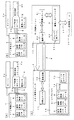
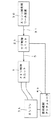
図1は、本発明の実施の一形態であるエンジン制御用コンピュータ装置の概略的な構成を示す。図1(a)および図1(b)は、異なる燃料を使用するエンジンに適用する使用時の形態をそれぞれ示し、図1(c)は制御情報の設定や書換えを行う開発時の形態を示す。本実施形態のエンジン制御用コンピュータ装置は、共通のメイン制御ユニット1と、サブ制御ユニット2a,2bとを含み、たとえば燃料の種類が異なるエンジン3a,3bに応じてサブ制御ユニット2a,2bを専用化している。燃料の種類が異なるエンジン3a,3bに対しては、異なる燃料噴射アクチュエータ4a,4bがそれぞれ必要であり、駆動回路などに要求される仕様が異なる。メイン制御ユニット1とサブ制御ユニット2a,2bとは、車載LANとして普及しているCAN(Controller Area Network )、LIN(Local Interconnect Network)、J1850、FlexRey などの通信ケーブル5でデータ通信可能な状態に接続される。
【0026】
メイン制御ユニット1は、プログラム制御によって複数種類のエンジン3a,3bのいずれかの動作を監視しながら、動作中の制御を行う。複数種類のエンジン3a,3bのいずれかに制御を適合させるための制御情報として、点火制御パラメータ6、噴射制御パラメータ7、およびISC制御パラメータ8などが書換え可能である。書換える元になる制御情報は、サブ制御ユニット2a,2bに、書換え用データ9として用意される。
【0027】
図1(c)に示すように、メイン制御ユニット1には、演算ユニット11、通信回路12およびユニット内メモリ13を含む。ユニット内メモリ13は、フラッシュROM、EEPROM、SRAM等で実現され、点火制御パラメータ6、噴射制御パラメータ7およびISC制御パラメータ8、およびその他14の制御情報を、チェック用データ15とともに格納して記憶可能な制御情報格納手段として機能する。フラッシュROMやEEPROMは、記憶する情報を、電源供給がなくなっても保持する不揮発性を有する。SRAMは、不揮発性を有するメモリよりも高速で動作させることができる。SRAMは不揮発性ではないけれども、電池などでバックアップすれば、実質的に不揮発性にすることができる。後述するように、制御情報を、動作に先立って転送するようにすれば、ユニット内メモリ13として揮発性のメモリを使用することもできる。演算ユニット11および通信回路12は、通信路としての通信ケーブル5を介して、サブ制御ユニット2a,2bから制御情報を取得し、ユニット内メモリ13に格納する制御情報取得手段として機能する。
【0028】
サブ制御ユニット2a,2bは、演算ユニット21、通信回路22、およびユニット内メモリ23を含む。ユニット内メモリ23は、フラッシュROMやEEPROMなど、不揮発性で書換え可能なメモリを使用する。ユニット内メモリ23には、書換え用パラメータ9やチェック用データ24が設定される。書換え用パラメータ9やチェック用データ24の設定や書換えは、外部にエンジン開発用ツール装置30を、通信ケーブル31を介して接続して行うことができる。通信ケーブル31には、一般的なLANケーブルや、パラレルまたはシリアルのインタフェース用ケーブルを使用することができる。
【0029】
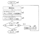
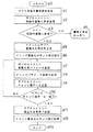
図2は、本実施形態のエンジン制御用コンピュータの制御手順についてのメインルーチンを示す。ステップa0から手順を開始し、メイン制御ユニット1とサブ制御ユニット2a,2bとを通信ケーブル5で接続すると、ステップa1では、相互間の通信が成立する。ステップa2では、サブ制御ユニット2a,2bからメイン制御ユニット1へ、書換え用パラメータ9を送信し、チェック用データ15の送信を要求する。メイン制御ユニット1では、演算ユニット11が、受信される書換え用パラメータ9に基づき、ユニット内メモリ13に格納される点火制御パラメータ6、噴射制御パラメータ7またはISC制御パラメータ8やその他14のパラメータ等を変更し、チェック用データ24を算出する。チェック用データ14は、たとえば、パリティやチェックサムなどとして生成する。ステップa3では、メイン制御ユニット1からサブ制御ユニット1a,2bに、チェック用データ15を送信する。ステップa4で、サブ制御ユニット2a,2bは、メイン制御ユニット1から受信するチェック用データ15と、ユニット内メモリ23に設定されているチェック用データ24とを比較し、異なっているときに、ステップa5で書換えルーチンを呼出す。ステップa5での書換えルーチンの終了後、またはステップa4でチェック用データ15,24が一致していると判断するときは、ステップa6で手順を終了する。
【0030】
以上のような制御手順によれば、サブ制御ユニット2a,2bを最初にメイン制御ユニット1に接続すれば、ステップa4のチェック用データの照合で、必要な場合には、最初から書換えパラメータの送信を行わせることができる。すなわち、サブ制御ユニット2a,2bが有する制御情報をメイン制御ユニット1が取得してプログラムに反映させるのは、サブ制御ユニット2a,2bが通信路を介してメイン制御ユニット1に接続されて行われる最初の通信成立時であるので、エンジン3a,3bに適合した制御を、動作の最初から行うことができる。このような最初の制御情報の転送は、無条件で行うようにすることもできる。
【0031】
また、サブ制御ユニット2a,2bの演算ユニット21および通信回路22は、チェック用データ9,15を使用する照合で、制御情報について情報の誤りが発生しているか否かを判断する誤り判断手段として機能し、誤り発生と判断するときは制御情報を再送して、メイン制御ユニット1は確実に制御情報を取得するので、制御情報の伝送誤りや、サブ制御ユニット2a,2bでの変更時に、メイン制御ユニット1のプログラムが論理的に誤動作したり、制御異常が発生するのを防止することができる。
【0032】
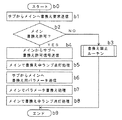
図3は、図2のステップa5で呼出される書換えルーチンの概略的な処理手順を示す。ステップb0から手順を開始し、ステップb1では、サブ制御ユニット2a,2bからメイン制御ユニット1に、書換え要求を送信する。ステップb2では、メイン制御ユニット1で、書換えが許可されている状態か否かを判断する。書換えの許可は、エンジンの運転に重大な影響を及す可能性が小さい条件でおこなわれる。書換えが許可されていなければ、ステップb3で書換え禁止ルーチンを実行する。ステップb2で書換え許可と判断するときは、ステップb4で、メイン制御ユニット1からサブ制御ユニット2a,2bに書換え許可信号を送信する。ステップb5では、図示を省略している書換え中ランプなどを点灯処理し、ステップb7でサブ制御ユニット2a,2bからメイン制御ユニット1に書換え用パラメータ9を送信する。ステップb8では、メイン制御ユニット1で、ユニット内メモリ13に格納されるパラメータに対して書換えが実行され、ステップb8で書換え中ランプを消灯するように処理する。ステップb8の終了、またはステップb3の終了で、ステップb9で処理手順を終了する。
【0033】
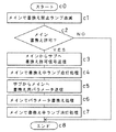
図4は、図3のステップb3の書換え禁止ルーチンの概略的な処理手順を示す。ステップc0から手順を開始し、ステップc1では、メイン制御ユニット1で、図示を省略している書換え禁止ランプを点滅させる。ステップc2では、メイン制御ユニット1で書換えが許可されているか否かを判断する。書換えが許可されているときには、ステップc3で、メイン制御ユニット1からサブ制御ユニット2a,2bに、書換え許可信号を送信する。ステップc4では、メイン制御ユニット1で書換え中ランプの点灯処理を行う。ステップc5で、サブ制御ユニット2a,2bからメイン制御ユニット1に書換え用パラメータ9が送信され、ステップc6でメイン制御ユニット内でのパラメータ書換えが実行される。書換えの実行後、ステップc7では、メイン制御ユニット1の書換え中ランプに対して消灯処理が行われ、ステップc8で処理を終了する。ステップc2で、書換え許可でないときも、ステップc8で処理を終了する。
【0034】
以上で説明しているように、本実施形態のエンジン制御用コンピュータ装置は、予め設定されるプログラムを実行して、エンジン3a,3bの動作を監視しながら制御信号を導出するメイン制御ユニット1と、メイン制御ユニット1に対してデータ通信用の通信路である通信ケーブル5を介して接続され、制御対象のエンジン3a,3bの予め定める部分的な機能について、メイン制御ユニット1のプログラムに付加する制御情報である書換え用パラメータ9を有し、メイン制御ユニットから1通信路を介して導出される制御信号に基づいて、部分的な機能としての燃料噴射アクチュエータ4a,4bなどの制御を行うサブ制御ユニットと2a,2bを含む。メイン制御ユニット1は、通信路を介してサブ制御ユニット2a,2bから制御情報である書換え用パラメータ9を取得する制御情報取得手段として機能する演算ユニット11および通信回路12と、制御情報取得手段によって取得される制御情報を点火制御パラメータ6、噴射制御パラメータ7およびISC制御パラメータ8として格納し、プログラムの実行中にプログラムから参照される制御情報格納手段として機能するユニット内メモリ13とを備える。
【0035】
複数種類のエンジン3a,3bで使用する燃料に合わせた燃料噴射アクチュエータ4a,4bなど、予め定める部分的な機能について、駆動回路などの電気的仕様等が異なる部分については、サブ制御ユニット2a,2bで対応させることができる。メイン制御ユニット1は、通信路を介してサブ制御ユニット2a,2bから制御情報を取得するので、サブ制御ユニット2a,2bを通信路を介して接続すれば、制御対象となるエンジン3a,3bの制御に必要な制御情報をサブ制御ユニット2a,2bから取得することができ、エンジン3a,3bの種類が異なっても共通のメイン制御ユニット1を使用することができる。エンジン3a,3bの種類の変更に伴う駆動回路の電気的仕様の変更は、サブ制御ユニット2a,2bの変更で対応することができ、メイン制御ユニット1については、エンジン3a,3bの種類の変更など適合する制御を、専用化や、プログラムやデータを変更するツールの導入なしに可能にすることができる。
【0036】
図5は、エンジン3bの開発中に、エンジン開発用ツール装置30を接続手段としての通信ケーブル31を介してサブ制御ユニット2bに接続し、書換え用パラメータ9を書換えながらエンジン3bを動作させ、燃料噴射アクチュエータ4bを制御する形態を示す。エンジン開発用ツール装置30は、エンジン開発部門に配置すればよく、生産ラインに配置する必要はない。メイン制御ユニット1は、たとえば他のエンジン3aの開発に合わせて完成しており、そのエンジン3aに対しては他のサブ制御ユニット2aおよび燃料噴射アクチュエータ4aを使用する。
【0037】
図6は、図5に示すようなエンジン制御中に、制御パラメータを書換える処理手順を示す。ステップd0から手順を開始し、ステップd1では、サブ制御ユニット2bから制御中書換え要求を発生する。ステップd2では、制御中書換え要求をサブ制御ユニット2bからメイン制御ユニット1に送信する。ステップd3では、メイン制御ユニット1で、制御中書換えが許可されているか否か判断する。許可されていなければ、ステップd4で、図4の書換え禁止ルーチンに移行する。ステップd3で、制御中書換えが許可されていると判断するときは、ステップd5でメイン制御ユニット1からサブ制御ユニット2bに、書換え許可信号を送信する。ステップd6では、メイン制御ユニット1で、書換え中ランプを点灯処理する。
【0038】
ステップd7では、サブ制御ユニット2bからメイン制御ユニット1へ書換えパラメータ9を送信する。この送信は、変更部分のみ、たとえば1バイトずつ等の部分処理に対応させることが好ましい。ステップd8では、メイン制御ユニット1でパラメータ書換えを実行する。ステップd9では、メイン制御ユニット1からサブ制御ユニット2bへ、チェック用データ15を送信する。ステップd10では、サブ制御ユニット2bで、チェック用データ15とチェック用データ9とが等しいか否か判断する。等しくないと判断するときは、ステップd7に戻り、書換えパラメータ9を再転送する。ステップd10で、等しいと判断するときは、ステップd11で、サブ制御ユニット2bからメイン制御ユニット1へ、書込み正常終了信号が送信され、ステップd12でメイン制御ユニット1は書換え中ランプの消灯処理を行い、ステップd13で処理を終了する。
【0039】
またエンジンの開発時ではない、実車両への搭載時などでは、エンジン3a,3bの始動時、冷間時、または車両の走行時を含むように予め設定される期間ではないときにのみ、制御情報の書換えが許可されるようにすることが好ましい。この期間に制御パラメータを書換えると、エンジンストップ等、好ましくない状況に陥るおそれがあるからである。
【0040】
なお、以上の説明では、メイン制御ユニット1のプログラムが動作中に参照する制御パラメータを書換えたり設定しているけれども、プログラムの一部を変更したり、追加したりすることもできる。また、エンジンの種類の違いは燃料の違いで説明しているけれども、同じ燃料でも異なるパーツを取付けたり、また、点火制御、ISC制御、噴射制御のうちの必ずしも全部を行わないような場合でも、本発明を同様に適用することができる。
【0041】
【発明の効果】
以上のように本発明によれば、複数種類のエンジンで予め定める部分的な機能について、駆動回路などの電気的仕様等が異なる部分については、サブ制御ユニットで対応させ、メイン制御ユニットは、通信路を介して制御対象となるエンジンの制御に必要な制御情報をサブ制御ユニットから取得することができるので、エンジンの種類が異なってもメイン制御ユニットを共通に使用することができる。メイン制御ユニットについては、エンジンの種類の変更など適合する制御を、専用化や、プログラムやデータを変更するツールの導入なしに可能にすることができる。車両に搭載するエンジンを、たとえばガソリン用を主に開発し、天然ガス燃料等を少量生産に対応させて開発するような場合でも、品種を削減して効率良く制御用コンピュータ装置を開発し、生産工程へプログラムの制御情報についての書換えツール等を導入する設備投資を不要とすることができる。
【0042】
また本発明によれば、メイン制御ユニットが実行するプログラムは共通化しておき、エンジンの種類の違いに、既存のメイン制御ユニットを使用して、サブ制御ユニットの変更で対応させることができる。
【0043】
また本発明によれば、メイン制御ユニットの制御情報取得手段は、制御情報の取得を条件成立時に限ることができ、サブ制御ユニットが有する制御情報をメイン制御ユニットのプログラムに適切に反映させることができる。
【0044】
また本発明によれば、サブ制御ユニットが通信路を介してメイン制御ユニットに接続されて行われる最初の通信成立時から、エンジンに適合した制御を行うことができる。
【0045】
また本発明によれば、たとえば、エンジンの開発部門などでは、サブ制御ユニットが有するメイン制御ユニットの制御情報を、設定したり書換えたりする編集用のツール装置を用意して、サブ制御ユニットをメイン制御ユニットに接続してエンジンの制御を行いながら、制御情報の編集を行い、エンジンに関する開発効率を高めることができる。
【0046】
また本発明によれば、サブ制御ユニットから取得してメイン制御ユニットの制御情報格納手段に格納される制御情報について、伝送誤り発生時や、サブ制御ユニットでの変更時に、メイン制御ユニットのプログラムが論理的に誤動作したり、制御異常が発生するのを防止することができ、信頼性を高めることができる。
【0047】
また本発明によれば、エンジンの始動時や冷間時、または車両の走行時を含む期間では、制御情報の変更は行われないので、エンジン制御のプログラム動作の変更等による影響で、エンジンが異常動作するのを防ぐことができる。
【図面の簡単な説明】
【図1】本発明の実施の一形態であるエンジン制御用コンピュータ装置の概略的な構成を示すブロック図である。
【図2】図1の本実施形態のエンジン制御用コンピュータの制御手順についてのメインルーチンを示すフローチャートである。
【図3】図2のステップa5で呼出される書換えルーチンの処理手順を示すフローチャートである。
【図4】図3のステップb3の書換え禁止ルーチンの概略的な処理手順を示すフローチャートである。
【図5】図1の実施形態で、エンジン3bを制御しながら制御パラメータを書換えるする形態を示すブロック図である。
【図6】図5に示すようなエンジン制御中に、制御パラメータを書換える処理手順を示すフローチャートである。
【符号の説明】
1 メイン制御ユニット
2a,2b サブ処理ユニット
3a,3b エンジン
4a,4b 燃料噴射アクチュエータ
5,31 通信ケーブル
6 点火制御パラメータ
7 噴射制御パラメータ
8 ISC制御パラメータ
9 書換え用パラメータ
11,21 演算ユニット
12,22 通信回路
13,23 ユニット内メモリ
15,24 チェック用データ[0001]
TECHNICAL FIELD OF THE INVENTION
The present invention relates to an engine control computer device that is mounted on an automobile and controls the operation of an engine.
[0002]
[Prior art]
2. Description of the Related Art Conventionally, automobile engines, particularly gasoline engines, perform ignition control, idle speed control (hereinafter abbreviated as “ISC”), injection control, and the like by an engine control computer device equipped with a microcomputer. In order to make full use of the performance of the engine, it is necessary to create an engine control computer device according to the engine to be controlled. However, when a plurality of types of engines to be controlled are predetermined, at least a part of a program and a plurality of types of control data are prepared, and the engine control computer device is shared by the plurality of types of engines. There is also.
[0003]
The use of alcohol as fuel for automobile engines and general-purpose engines is also being studied. In controlling the ignition timing of an internal combustion engine, a plurality of maps in which basic control values are predetermined for each alcohol concentration are provided, and the map is switched according to the alcohol concentration in use (for example, see Patent Document 1). For an engine that uses gasoline and alcohol as fuel, an optimal engine control amount is prepared as a map for a plurality of alcohol mixing ratios, and weighted interpolation calculations are performed for intermediate mixing ratios. The engine is controlled (for example, see Patent Document 2). In a two-stroke engine in which gasoline and alcohol mixed fuel are selectively used, an air-fuel ratio correction map suitable for gasoline and alcohol is stored, and a map suitable for gasoline is used. When the reference combustion pressure is exceeded, it is determined that the alcohol-mixed fuel is used, and the map is switched (for example, see Patent Document 3).
[0004]
In a general-purpose engine that selectively uses gas fuel and liquid fuel, the fuel supply control device is provided with three types of programs for a liquid fuel engine, a gas fuel engine, and an engine for switching between liquid fuel and gas fuel (for example, Patent Document 4). In an internal combustion engine that is operated using a second type of fuel such as LPG (liquefied petroleum gas) in addition to the first fuel such as petroleum, the second control device uses the second type of fuel when the second type of fuel is used. The fuel supply amount is controlled, and process parameters, operation parameters, and the like are adjusted with the first control device (for example, see Patent Document 5).
[0005]
[Patent Document 1]
Japanese Patent Publication No. 7-13508
[Patent Document 2]
JP-A-5-195938
[Patent Document 3]
JP-A-6-66175
[Patent Document 4]
JP 2000-145488 A
[Patent Document 5]
Japanese Patent Publication No. 9-505653
[0006]
[Problems to be solved by the invention]
In the case of using a gasoline engine and another fuel engine as automobile engines, it is conceivable that a program suitable for each engine is prepared in an engine control computer device and switched as in
[0007]
Preparing programs corresponding to the number of types of engines to be used imposes a heavy burden on program development. Further, even if it is known that gasoline and other fuels are basically used for the same engine, development of other fuels may be later than that of gasoline. In such a case, the main control unit must be dedicated to the fuel or the program and control parameters of the main control unit must be set or rewritten later.
[0008]
Dedicating the main control unit according to the type of engine complicates production management. Also, compared to gasoline engines, vehicles equipped with engines of other fuels are also produced in small quantities, so developing a dedicated main control unit will increase production costs. In order to be able to set and rewrite the program and control parameters of the main control unit later, it is necessary to introduce a tool for setting and rewriting. Introducing such a tool to a vehicle assembly factory and using it on a production line increases the production cost of the vehicle due to the cost of introducing the tool itself and the cost of the working time required for using the tool. .
[0009]
An object of the present invention is to provide an engine control computer device that enables suitable control such as change of an engine type without specializing or introducing a tool for changing a program or data.
[0010]
[Means for Solving the Problems]
The present invention is an engine control computer device mounted on a vehicle and controlling an engine,
A main control unit that executes a preset program to control the engine;
Connected to the main control unit via a communication path for data communication, for a predetermined partial function of the engine to be controlled, including a sub-control unit having control information added to the program of the main control unit,
The main control unit is
Control information acquisition means for acquiring the control information from the sub-control unit via a communication path,
An engine control computer device, comprising: control information storage means for storing control information obtained by control information obtaining means and being referred to by the program during execution of the program.
[0011]
According to the present invention, an engine control computer device is mounted on a vehicle and includes a main control unit and a sub control unit for controlling an engine. The main control unit executes a preset program to control the engine. The sub-control unit is connected to the main control unit via a communication path for data communication, and has control information to be added to a program of the main control unit for a predetermined partial function of the engine to be controlled.
[0012]
With respect to partial functions determined in advance by a plurality of types of engines, portions having different electrical specifications such as drive circuits can be handled by a sub-control unit. The main control unit stores control information obtaining means for obtaining the control information from the sub control unit via the communication path, and control information obtained by the control information obtaining means, and is referred to by the program during execution of the program. If the sub-control unit is connected via a communication path, control information necessary for controlling the engine to be controlled can be obtained from the sub-control unit. However, a common main control unit can be used. Changes in the electrical specifications of the drive circuit that accompany changes in the type of engine can be handled by changing the sub-control unit.For the main control unit, specialized control such as changing the type of engine, This can be done without introducing tools to change programs and data.
[0013]
In the present invention, the control information is a control parameter used in a program executed by the main control unit.
[0014]
According to the present invention, the program executed by the main control unit is shared, control parameters are obtained from a sub-control unit adapted to the engine to be controlled, and the control parameters are obtained by referring to the program and performing control according to the engine. It can be performed.
[0015]
In the present invention, the control information acquisition means of the main control unit acquires the control information when a predetermined condition is satisfied, and stores the control information in the control information storage means.
[0016]
According to the present invention, the control information obtaining means of the main control unit obtains the control information of the sub-control unit and stores it in the control information storage means when the predetermined condition is satisfied. This can be limited to a certain time, and by setting appropriate conditions, the control information of the sub-control unit can be appropriately reflected in the program of the main control unit.
[0017]
Further, in the present invention, the time when the predetermined condition is satisfied is a time when the first communication is established after the sub-control unit is connected via the communication path.
[0018]
According to the present invention, the main control unit acquires the control information of the sub-control unit and reflects it in the program because the sub-control unit is connected to the main control unit via a communication path and the first communication is established. Since it is time, control suitable for the engine can be performed from the beginning of the operation.
[0019]
Further, in the present invention, the sub-control unit includes a connection unit capable of connecting a tool device capable of editing the control information,
The predetermined condition is satisfied when a tool device is connected to the connection means of the sub-control unit and editing of control information is performed.
[0020]
According to the present invention, for example, in a development section of a new engine, a sub-control unit suitable for the engine under development is connected to the existing main control unit, and the sub-control unit has Since the control information can be edited by setting or rewriting with the tool device and reflected in the program of the main control unit, the development efficiency of the engine can be improved.
[0021]
In the present invention, the control information acquisition means of the main control unit transmits check data for control information stored in the control information storage means during communication with the sub control unit,
The sub-control unit includes an error determination unit that receives the check data and determines whether an information error has occurred in the control information.
The predetermined condition is satisfied when the error determining means determines that an error has occurred.
[0022]
According to the present invention, for control information acquired from the sub control unit and stored in the control information storage means of the main control unit, the control information acquisition means of the main control unit transmits check data to the sub control unit, If the error determination means of the control unit determines that an error has occurred, the control information obtaining means obtains the control information, so that when a control information transmission error or a change in the sub-control unit occurs, the program of the main control unit is It is possible to prevent a logical malfunction or a control abnormality.
[0023]
Further, in the present invention, the predetermined condition is set in advance so as not to include at least when the engine is started, when the engine is cold, or when the vehicle is running.
[0024]
According to the present invention, when the engine is started, when the engine is cold, or when the vehicle is not running, the condition is satisfied, and control information can be obtained and stored in the control information storage means. Therefore, it is possible to prevent the engine from operating abnormally due to the influence of a change in the control information or the like.
[0025]
BEST MODE FOR CARRYING OUT THE INVENTION
FIG. 1 shows a schematic configuration of an engine control computer device according to an embodiment of the present invention. 1 (a) and 1 (b) show a use mode applied to an engine using a different fuel, respectively, and FIG. 1 (c) shows a development mode in which control information is set or rewritten. . The engine control computer device of the present embodiment includes a common
[0026]
The
[0027]
As shown in FIG. 1C, the
[0028]
The
[0029]
FIG. 2 shows a main routine for a control procedure of the engine control computer of the present embodiment. When the procedure is started from step a0 and the
[0030]
According to the above control procedure, if the
[0031]
The arithmetic unit 21 and the communication circuit 22 of the
[0032]
FIG. 3 shows a schematic processing procedure of the rewriting routine called in step a5 of FIG. The procedure is started from step b0. In step b1, a rewrite request is transmitted from the
[0033]
FIG. 4 shows a schematic processing procedure of the rewrite prohibition routine in step b3 of FIG. The procedure starts from step c0. In step c1, the
[0034]
As described above, the engine control computer device of the present embodiment executes the preset program to monitor the operation of the engines 3a and 3b and derive the control signals while monitoring the operation of the engines 3a and 3b. Is connected to the
[0035]
Regarding predetermined partial functions such as fuel injection actuators 4a and 4b adapted to the fuels used in a plurality of types of engines 3a and 3b,
[0036]
FIG. 5 shows that during the development of the engine 3b, the engine
[0037]
FIG. 6 shows a processing procedure for rewriting control parameters during engine control as shown in FIG. The procedure starts from step d0, and in step d1, a
[0038]
In step d7, the rewriting
[0039]
In addition, when the engine 3a, 3b is not mounted at the time of starting, when the engine is cold, or when the vehicle is running, the control is performed only when the engine 3a, 3b is mounted on an actual vehicle, not when the engine is developed. Preferably, rewriting of information is permitted. This is because if the control parameters are rewritten during this period, an undesirable situation such as an engine stop may occur.
[0040]
In the above description, although the control parameters referred to during the operation of the program of the
[0041]
【The invention's effect】
As described above, according to the present invention, for a partial function predetermined by a plurality of types of engines, portions having different electrical specifications such as drive circuits are handled by a sub control unit, and the main control unit Since control information necessary for controlling the engine to be controlled can be obtained from the sub-control unit via the road, the main control unit can be commonly used even if the type of engine is different. With respect to the main control unit, it is possible to perform suitable control such as changing the type of engine without specializing or introducing a tool for changing programs and data. Even if the engine to be mounted on the vehicle is mainly developed for gasoline, for example, and natural gas fuel etc. is developed for small-volume production, the number of varieties will be reduced and control computer equipment will be developed and produced efficiently. This eliminates the need for capital investment for introducing a tool for rewriting program control information into the process.
[0042]
Further, according to the present invention, the program executed by the main control unit can be made common, and the difference in the type of engine can be dealt with by changing the sub-control unit using the existing main control unit.
[0043]
Further, according to the present invention, the control information acquisition means of the main control unit can restrict the acquisition of the control information when the condition is satisfied, and can appropriately reflect the control information of the sub-control unit in the program of the main control unit. it can.
[0044]
Further, according to the present invention, it is possible to perform control suitable for the engine from the first communication established when the sub-control unit is connected to the main control unit via the communication path.
[0045]
According to the present invention, for example, an engine development department or the like prepares an editing tool device for setting and rewriting the control information of the main control unit of the sub control unit, and While controlling the engine by connecting to the control unit, the control information can be edited and the development efficiency of the engine can be improved.
[0046]
Further, according to the present invention, the control information acquired from the sub control unit and stored in the control information storage means of the main control unit, when a transmission error occurs or when the control information is changed in the sub control unit, the program of the main control unit is It is possible to prevent a logical malfunction or a control abnormality from occurring, thereby improving reliability.
[0047]
Further, according to the present invention, the control information is not changed during the period including the time of starting the engine, the time of the cold, or the time of running of the vehicle. Abnormal operation can be prevented.
[Brief description of the drawings]
FIG. 1 is a block diagram showing a schematic configuration of an engine control computer device according to an embodiment of the present invention.
FIG. 2 is a flowchart showing a main routine of a control procedure of the engine control computer of the embodiment of FIG. 1;
FIG. 3 is a flowchart showing a processing procedure of a rewriting routine called in step a5 of FIG. 2;
FIG. 4 is a flowchart illustrating a schematic processing procedure of a rewrite prohibition routine in step b3 of FIG. 3;
FIG. 5 is a block diagram showing a mode of rewriting control parameters while controlling an engine 3b in the embodiment of FIG.
6 is a flowchart showing a processing procedure for rewriting control parameters during engine control as shown in FIG.
[Explanation of symbols]
1 Main control unit
2a, 2b Sub-processing unit
3a, 3b engine
4a, 4b fuel injection actuator
5,31 Communication cable
6 Ignition control parameters
7 Injection control parameters
8 ISC control parameters
9 Rewriting parameters
11,21 arithmetic unit
12,22 Communication circuit
13,23 Unit memory
15, 24 Check data
Claims (7)
予め設定されるプログラムを実行して、エンジンを制御するメイン制御ユニットと、
メイン制御ユニットに対してデータ通信用の通信路を介して接続され、制御対象のエンジンの予め定める部分的な機能について、メイン制御ユニットのプログラムに付加する制御情報を有するサブ制御ユニットとを含み、
メイン制御ユニットは、
通信路を介してサブ制御ユニットから該制御情報を取得する制御情報取得手段と、
制御情報取得手段によって取得される制御情報を格納し、プログラムの実行中にプログラムから参照される制御情報格納手段とを備えることを特徴とするエンジン制御用コンピュータ装置。An engine control computer device mounted on a vehicle and controlling an engine,
A main control unit that executes a preset program to control the engine;
Connected to the main control unit via a communication path for data communication, for a predetermined partial function of the engine to be controlled, including a sub-control unit having control information added to the program of the main control unit,
The main control unit is
Control information acquisition means for acquiring the control information from the sub-control unit via a communication path,
An engine control computer device, comprising: control information storage means for storing control information acquired by control information acquisition means and being referred to by the program during execution of the program.
前記予め定める条件成立時は、サブ制御ユニットの接続手段にツール装置が接続されて、制御情報に対する編集が行われるときであることを特徴とする請求項3または4記載のエンジン制御用コンピュータ装置。The sub-control unit includes a connection unit capable of connecting a tool device capable of editing the control information,
5. The engine control computer device according to claim 3, wherein the predetermined condition is satisfied when a tool device is connected to the connection means of the sub-control unit to edit control information.
サブ制御ユニットは、該チェック用データを受信して、制御情報について情報の誤りが発生しているか否かを判断する誤り判断手段を備え、
前記予め定める条件成立時は、誤り判断手段が誤り発生と判断するときであることを特徴とする請求項3〜5のいずれかに記載のエンジン制御用コンピュータ装置。The control information acquisition means of the main control unit, during communication with the sub-control unit, transmits check data for control information stored in the control information storage means,
The sub-control unit includes an error determination unit that receives the check data and determines whether an information error has occurred in the control information.
6. The engine control computer device according to claim 3, wherein the predetermined condition is satisfied when an error determining unit determines that an error has occurred.
Priority Applications (1)
| Application Number | Priority Date | Filing Date | Title |
|---|---|---|---|
| JP2003099618A JP2004308452A (en) | 2003-04-02 | 2003-04-02 | Computer device for engine control |
Applications Claiming Priority (1)
| Application Number | Priority Date | Filing Date | Title |
|---|---|---|---|
| JP2003099618A JP2004308452A (en) | 2003-04-02 | 2003-04-02 | Computer device for engine control |
Publications (1)
| Publication Number | Publication Date |
|---|---|
| JP2004308452A true JP2004308452A (en) | 2004-11-04 |
Family
ID=33464010
Family Applications (1)
| Application Number | Title | Priority Date | Filing Date |
|---|---|---|---|
| JP2003099618A Withdrawn JP2004308452A (en) | 2003-04-02 | 2003-04-02 | Computer device for engine control |
Country Status (1)
| Country | Link |
|---|---|
| JP (1) | JP2004308452A (en) |
Cited By (3)
| Publication number | Priority date | Publication date | Assignee | Title |
|---|---|---|---|---|
| JP2008049731A (en) * | 2006-08-22 | 2008-03-06 | Blitz:Kk | Vehicle information display |
| JP2008082329A (en) * | 2006-08-29 | 2008-04-10 | Honda Motor Co Ltd | Fuel injection control device |
| JP2012026316A (en) * | 2010-07-21 | 2012-02-09 | Keihin Corp | Engine control system |
-
2003
- 2003-04-02 JP JP2003099618A patent/JP2004308452A/en not_active Withdrawn
Cited By (3)
| Publication number | Priority date | Publication date | Assignee | Title |
|---|---|---|---|---|
| JP2008049731A (en) * | 2006-08-22 | 2008-03-06 | Blitz:Kk | Vehicle information display |
| JP2008082329A (en) * | 2006-08-29 | 2008-04-10 | Honda Motor Co Ltd | Fuel injection control device |
| JP2012026316A (en) * | 2010-07-21 | 2012-02-09 | Keihin Corp | Engine control system |
Similar Documents
| Publication | Publication Date | Title |
|---|---|---|
| JP4506868B2 (en) | Electronic control unit | |
| JP2008057413A (en) | Method and device for storing characteristics of vehicle | |
| EP0954863B1 (en) | System and method for memory reset of a vehicle controller | |
| JP4457969B2 (en) | VEHICLE CONTROL METHOD AND ELECTRONIC CONTROL DEVICE | |
| JP4503256B2 (en) | Method and apparatus for starting or stopping an engine-driven vehicle | |
| JP3835312B2 (en) | Electronic control device for vehicle | |
| EP3051419B1 (en) | Vehicle computer system with data backup | |
| JP2012224315A (en) | In-vehicle electronic control device, diagnostic tool and diagnostic system | |
| CN110872998B (en) | Method for verifying CVVD position learning result and CVVD system for verifying CVVD position learning result | |
| EP1494099B1 (en) | Electronic system with a plurality of electronic units | |
| JP2004308452A (en) | Computer device for engine control | |
| JP4412222B2 (en) | VEHICLE CONTROL METHOD AND ELECTRONIC CONTROL DEVICE | |
| JP2007138878A (en) | Control device of internal combustion engine | |
| US20110010029A1 (en) | Method for Simplifying Torque Distribution in Multiple Drive Systems | |
| US7182065B2 (en) | Vehicle and method for operating an engine in a vehicle | |
| JP4423824B2 (en) | Control device for internal combustion engine | |
| JPH0777093A (en) | Method and device for diagnosing idle speed control system | |
| JP5111486B2 (en) | Update apparatus and update method for control program | |
| JP2010112351A (en) | Engine testing apparatus | |
| EP1106809A2 (en) | Electronic control apparatus having mode check funktion | |
| Wierzbicki | Evaluation of on-board diagnostic systems in contemporary vehicles | |
| KR102552081B1 (en) | Continuously variable valve duration apparatus and controlling method thereof | |
| CN114856846B (en) | Method and device for arranging master ECU and slave ECU for vehicle, processor, and vehicle | |
| JP7334552B2 (en) | electronic controller | |
| JPH01224636A (en) | Vehicle diagnosing device |
Legal Events
| Date | Code | Title | Description |
|---|---|---|---|
| A300 | Application deemed to be withdrawn because no request for examination was validly filed |
Free format text: JAPANESE INTERMEDIATE CODE: A300 Effective date: 20060606 |