JP2004306776A - Trailer hitch device for automobile - Google Patents
Trailer hitch device for automobile Download PDFInfo
- Publication number
- JP2004306776A JP2004306776A JP2003103030A JP2003103030A JP2004306776A JP 2004306776 A JP2004306776 A JP 2004306776A JP 2003103030 A JP2003103030 A JP 2003103030A JP 2003103030 A JP2003103030 A JP 2003103030A JP 2004306776 A JP2004306776 A JP 2004306776A
- Authority
- JP
- Japan
- Prior art keywords
- floor side
- rear floor
- trailer hitch
- insert
- extension
- Prior art date
- Legal status (The legal status is an assumption and is not a legal conclusion. Google has not performed a legal analysis and makes no representation as to the accuracy of the status listed.)
- Pending
Links
Images


Classifications
-
- B—PERFORMING OPERATIONS; TRANSPORTING
- B60—VEHICLES IN GENERAL
- B60D—VEHICLE CONNECTIONS
- B60D1/00—Traction couplings; Hitches; Draw-gear; Towing devices
- B60D1/48—Traction couplings; Hitches; Draw-gear; Towing devices characterised by the mounting
- B60D1/485—Traction couplings; Hitches; Draw-gear; Towing devices characterised by the mounting mounted by means of transversal members attached to the frame of a vehicle
-
- B—PERFORMING OPERATIONS; TRANSPORTING
- B60—VEHICLES IN GENERAL
- B60D—VEHICLE CONNECTIONS
- B60D1/00—Traction couplings; Hitches; Draw-gear; Towing devices
- B60D1/01—Traction couplings or hitches characterised by their type
- B60D1/06—Ball-and-socket hitches, e.g. constructional details, auxiliary devices, their arrangement on the vehicle
Landscapes
- Engineering & Computer Science (AREA)
- Transportation (AREA)
- Mechanical Engineering (AREA)
- Body Structure For Vehicles (AREA)
Abstract
Description
【0001】
【発明の属する技術分野】
この発明は、自動車にトレーラを連結するために用いるトレーラヒッチ装置に関する。
【0002】
【従来の技術】
トレーラを牽引するには、自動車の後部にトレーラヒッチ装置を設ける必要がある。乗用車等に設けるトレーラヒッチ装置は、例えば車体後方に延びる左右一対のリヤフロアサイドメンバエクステンション部材の側面に、トレーラヒッチ装置のクロスメンバ部材の両端に設けたブラケット部をボルトによって固定している。
【0003】
従来のトレーラヒッチ装置の一例として、下記特許文献1に示されるように、車体(ボデー)の幅方向に沿って配置されるヒッチメンバービームと、このヒッチメンバービームの両端部から車体前方に突出する左右一対のヒッチステ−と、前記ヒッチメンバービームの中央部に支持ブラケットを介して固定されたトレーラヒッチなどからなるトレーラヒッチ装置が提案されている。
【0004】
【特許文献1】
実用新案登録第2604008号公報
【0005】
【発明が解決しようとする課題】
従来のトレーラヒッチ装置のように、リヤフロアサイドメンバエクステンション部材の側面あるいは下方からトレーラヒッチ装置のブラケット部をボルトによって締結(いわゆる外付け)する場合、所望の取付強度を得るには、ブラケット部の板厚をかなり大きくする必要がある。
【0006】
特に、近年は自動車で牽引できるトレーラ重量を大きくしたいという傾向があり、車体に対するトレーラヒッチ装置の取付部を強化することが望まれている。しかし、取付部を強化するために前記ブラケット部の板厚等を大きくすると、重量がますます大きくなってしまう。また、大形化したブラケット部が周囲の部材および各種補器類と干渉する可能性が生じるなど、改良の余地がある。
【0007】
また、従来のように重量の大きなトレーラヒッチ装置を、車体の下側からリヤフロアサイドメンバエクステンション部材の側面の所望位置に取付ける作業は、かなりの労力を必要とする。特許文献1も上記と同様の問題点がある。
【0008】
従ってこの発明の目的は、軽量化が図れかつ車体に取付けることが比較的容易なトレーラヒッチ装置を提供することにある。
【0009】
【課題を解決するための手段】
本発明は、車体後方に延びる左右一対のリヤフロアサイドメンバエクステンション部材に取付けるトレーラヒッチ装置であって、前記各リヤフロアサイドメンバエクステンション部材の後端の開口部から該リヤフロアサイドメンバエクステンション部材に挿入され、該リヤフロアサイドメンバエクステンション部材にボルトによって固定されるパイプ材からなるインサート部材と、前記各インサート部材の後端部に固定されて前記車体の幅方向に延びるクロスメンバ部材と、前記クロスメンバ部材の前記幅方向の中間部に固定されたトレーラヒッチ部材とを具備している。
【0010】
この発明の好ましい形態では、前記リヤフロアサイドメンバエクステンション部材の前記開口部にフランジ部材が設けられ、前記インサート部材には、該インサート部材が前記リヤフロアサイドメンバエクステンション部材の所定位置まで挿入された状態において前記フランジ部材に当接する取付プレートが設けられている。
【0011】
またこの発明の好ましい形態では、前記リヤフロアサイドメンバエクステンション部材と前記インサート部材との間に配置されるリンフォース部材をさらに備え、該リンフォース部材には、該リンフォース部材が前記リヤフロアサイドメンバエクステンション部材の所定位置まで挿入された状態において前記フランジ部材に当接するストッパ部が設けられている。
【0012】
【発明の実施の形態】
以下に本発明の一実施形態について、図1から図4を参照して説明する。
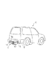
図3に示す自動車10の後部にトレーラヒッチ装置11が取付けられている。このトレーラヒッチ装置11は、車体12の一部である左右一対のリヤフロアサイドメンバエクステンション部材13に取付けられている。リヤフロアサイドメンバエクステンション部材13は車体12の後方に延びている。
【0013】
図1と図2は、トレーラヒッチ装置11の車体中央部付近から右側の部位を示している。トレーラヒッチ装置11の左側の部位は、右側の部位と左右対称形状であるが、基本的な構成は左右とも同じであるため、以下に右側の部位を代表して説明する。
【0014】
図1と図4等に示すようにリヤフロアサイドメンバエクステンション部材13は、左右一対の側壁15,16と、側壁15,16をつなぐ底壁17と、一方の側壁15の上端から水平方向に延びるフランジ状の折曲縁部18などを備え、上面側が開口している。リヤフロアサイドメンバエクステンション部材13の後端の開口部20に、車体の一部であるフランジ部材21が設けられている。フランジ部材21は、車体後部を構成するリヤエンドパネル(図示せず)に設けられている。
【0015】
フランジ部材21に複数のボルト25が固定されている。これらのボルト25はそれぞれ車体後方に向かって突出している。フランジ部材21の開口部26は、リヤフロアサイドメンバエクステンション部材13の開口部20と対応した位置に形成されている。トレーラヒッチ装置11を装着しない場合、このフランジ部材21に、リヤバンパビーム(図示しない)がボルト25によって固定される。
【0016】
リヤフロアサイドメンバエクステンション部材13の一方の側壁15に、ボルト30を通す複数の孔31が形成されている。これらの孔31は、リヤフロアサイドメンバエクステンション部材13の長手方向(車体前後方向)に所定間隔で形成されている。底壁17にも、ボルト32を通す複数の孔33が形成されている。これらの孔33は、リヤフロアサイドメンバエクステンション部材13の長手方向に所定間隔で形成されている。
【0017】
本実施形態のトレーラヒッチ装置11はインサート部材40を備えている。インサート部材40は、リヤフロアサイドメンバエクステンション部材13の後端の開口部20からリヤフロアサイドメンバエクステンション部材13の長手方向に挿入される。このインサート部材40は、図4に示すように断面がおおむね四角形の鋼製パイプ材からなる。
【0018】
さらに詳しくはこのインサート部材40は、ほぼ平坦な両側壁41,42と、上壁43および下壁44と、これら各壁41〜44をつなぐ4分の1の円弧からなる丸みを帯びたコーナー部45とを有している。
【0019】
一方の側壁41には、リヤフロアサイドメンバエクステンション部材13の前記孔31と対応した位置に、ボルト30を挿通する孔46が形成されている。下壁44には、リヤフロアサイドメンバエクステンション部材13の前記孔33と対応した位置に、ボルト32を挿通する孔47が形成されている。インサート部材40の内部に、前記ボルト30,32が螺合するナット部材50,51が取付けられている。
【0020】
インサート部材40の後端部40aに、フランジ状の取付プレート55が,例えば溶接によって固定されている。インサート部材40がリヤフロアサイドメンバエクステンション部材13の開口部20から所定位置まで挿入された状態において、この取付プレート55がフランジ部材21に当接することにより、インサート部材40の挿入方向の位置決めがなされるようになっている。
【0021】
取付プレート55に、前記フランジ部材21のボルト25を挿通する複数の孔56が形成されている。この孔56に挿入されたボルト25に、ナット部材57が螺合される。
【0022】
インサート部材40の後端部40aには、前記取付プレート55の後側に、クロスメンバ取付用ブラケット60を介して、クロスメンバ部材61が取付けられている。本実施形態では、インサート部材40の後端部40aの下面に補助ブラケット62が溶接され、この補助ブラケット62とインサート部材40の後端部40aの側面に、クロスメンバ部材61の両端に溶接された連結板63(一方のみ図示する)がボルト64によって固定される。
【0023】
クロスメンバ部材61は、例えば断面が円形の鋼製パイプ材からなり、車体12の幅方向に延びている。クロスメンバ部材61の長手方向中間部、すなわち車体12の幅方向の中間部に、トレーラヒッチ部材70がブラケットアセンブリ71を介して固定されている。
【0024】
ブラケットアセンブリ71は、クロスメンバ部材61の下方に延びるブラケットアーム72と、ブラケットアーム72の下部から車体後方に延びる連結ベース73などを含んでいる。連結ベース73の上面にトレーラヒッチ部材70が固定されている。
【0025】
リヤフロアサイドメンバエクステンション部材13とインサート部材40との間に、補強手段として機能するリンフォース部材80が挟まれている。このリンフォース部材80は、リヤフロアサイドメンバエクステンション部材13の側壁15,16に沿う立上がり部81,82と、リヤフロアサイドメンバエクステンション部材13の底壁17に沿う底部83とを有している。
【0026】
立上がり部81と底部83には、リヤフロアサイドメンバエクステンション部材13の前記孔31,33と対応した位置に、ボルト30,32を通すための孔84,85が形成されている。
【0027】
リンフォース部材80の前記立上がり部81と底部83の後端に、位置決め手段として機能するストッパ部90,91が設けられている。これらのストッパ部90,91は、リヤフロアサイドメンバエクステンション部材13の後端部を外方に折曲することによって形成されている。
【0028】
リンフォース部材80がリヤフロアサイドメンバエクステンション部材13の開口部20から所定位置まで挿入された状態において、ストッパ部90,91がフランジ部材21に当接することにより、リンフォース部材80の挿入方向の位置決めがなされるとともに、リンフォース部材80の孔84,85と、リヤフロアサイドメンバエクステンション部材13の孔31,33の位置が、互いに合致するようになっている。
【0029】
次に、トレーラヒッチ装置11を車体12に取付ける手順について説明する。
【0030】
リンフォース部材80をフランジ部材21の開口部26からリヤフロアサイドメンバエクステンション部材13に挿入する。リンフォース部材80がリヤフロアサイドメンバエクステンション部材13の所定位置まで挿入されると、ストッパ部90,91がフランジ部材21に当接することにより、リンフォース部材80の孔84,85と、リヤフロアサイドメンバエクステンション部材13の孔31,33の位置が合う。
【0031】
そののち、車体12の後方から、トレーラヒッチ装置11のインサート部材40をフランジ部材21の開口部26からリヤフロアサイドメンバエクステンション部材13に挿入することにより、インサート部材40をリンフォース部材80に重ねる。また、フランジ部材21のボルト25を取付プレート55の孔56に挿入する。こうすることにより、トレーラヒッチ装置11をリヤフロアサイドメンバエクステンション部材13の所定位置に仮に置くことができる。
【0032】
インサート部材40がリヤフロアサイドメンバエクステンション部材13の所定位置まで挿入されると、取付プレート55がフランジ部材21に当接することにより、インサート部材40の孔46,47と、リヤフロアサイドメンバエクステンション部材13の孔31,33の位置が合う。
【0033】
この状態で、リヤフロアサイドメンバエクステンション部材13の側方から、ボルト30を孔31,46,84に挿入し、ナット部材50に螺合させて締付ける。また、リヤフロアサイドメンバエクステンション部材13の下側から、ボルト32を孔33,47,85に挿入し、ナット部材51に螺合させて締付ける。
【0034】
こうすることにより、インサート部材40がリヤフロアサイドメンバエクステンション部材13の所定位置に強固に固定される。また、取付プレート55の後側から、ナット部材57をフランジ部材21のボルト25に螺合させて締付けることにより、取付プレート55をフランジ部材21に締結する。
【0035】
このように本実施形態によれば、インサート部材40をリヤフロアサイドメンバエクステンション部材13の所定位置まで挿入して仮に置いた状態のもとで、ボルト30,32による本固定を行なうことができる。このため、トレーラヒッチ装置11の車体12への取付作業を安全にかつ容易に行なうことができる。
【0036】
また、パイプ材からなるインサート部材40をリヤフロアサイドメンバエクステンション部材13の内側に挿入してリヤフロアサイドメンバエクステンション部材13の外側からボルト30,32によって固定するため、図4に2点鎖線で示す従来のブラケット部材Aのようにリヤフロアサイドメンバエクステンション部材13の外側から重ねてボルト締めする場合と比較して、インサート部材40の壁厚が従来のブラケット部材Aの板厚よりも小さくてすみ、高剛性でありながら軽量に構成することができる。
【0037】
また、図4に示す従来のブラケット部材Aは、リヤフロアサイドメンバエクステンション部材13の下方側のスペースを占めるため、例えばマフラーなどの周囲部材との干渉を考慮する必要があるが、本実施形態では、リヤフロアサイドメンバエクステンション部材13の内部にインサート部材40が挿入されるため、マフラー等の周囲部材との干渉を避けることができる。
【0038】
【発明の効果】
請求項1に記載した発明によれば、トレーラヒッチ装置をより軽量に構成することができ、しかもリヤフロアサイドメンバエクステンション部材の下方のスペースを占有することなくコンパクトに取付けることができる。また、インサート部材をリヤフロアサイドメンバエクステンション部材に挿入して仮置きした状態でボルト締め作業を行なうことができるため、車体に対する組付作業が容易である。
【0039】
請求項2に記載した発明によれば、請求項1による効果に加え、インサート部材をリヤフロアサイドメンバエクステンション部材の所定位置に容易に位置決めすることができ、リヤフロアサイドメンバエクステンション部材側のフランジ部材とインサート部材側の取付プレートを利用して、インサート部材を所定位置に取付けることができる。
【0040】
請求項3に記載した発明によれば、リンフォース部材によってインサート部材の取付部の強度を高めることができ、かつ、リンフォース部材をリヤフロアサイドメンバエクステンション部材の所定位置に容易に位置決めすることができる。
【図面の簡単な説明】
【図1】本発明の一実施形態のトレーラヒッチ装置の分解斜視図。
【図2】図1に示されたトレーラヒッチ装置をリヤフロアサイドメンバエクステンション部材に取付けた状態の斜視図。
【図3】図1に示されたトレーラヒッチ装置を備えた自動車の斜視図。
【図4】図2中のF4−F4線に沿うトレーラヒッチ装置の断面図。
【符号の説明】
11…トレーラヒッチ装置
12…車体
13…リヤフロアサイドメンバエクステンション部材
20…開口部
21…フランジ部材
30,32…ボルト
40…インサート部材
61…クロスメンバ部材
70…トレーラヒッチ部材
80…リンフォース部材
90,91…ストッパ部[0001]
TECHNICAL FIELD OF THE INVENTION
The present invention relates to a trailer hitch device used for connecting a trailer to an automobile.
[0002]
[Prior art]
Tow a trailer, it is necessary to provide a trailer hitch device at the rear of the vehicle. In a trailer hitch device provided in a passenger car or the like, for example, bracket portions provided at both ends of a cross member member of the trailer hitch device are fixed to side surfaces of a pair of left and right rear floor side member extension members extending rearward of the vehicle body with bolts.
[0003]
As an example of a conventional trailer hitch device, as shown in Patent Document 1 below, a hitch member beam arranged along the width direction of a vehicle body (body), and a pair of left and right members projecting forward from the both ends of the hitch member beam toward the front of the vehicle body. And a trailer hitch device including a trailer hitch fixed to a center portion of the hitch member beam via a support bracket.
[0004]
[Patent Document 1]
Japanese Utility Model Registration No. 2604008
[Problems to be solved by the invention]
When a bracket portion of a trailer hitch device is fastened by bolts (so-called external attachment) from a side surface or a lower portion of a rear floor side member extension member as in a conventional trailer hitch device, a desired mounting strength is obtained by using a plate of the bracket portion. The thickness needs to be quite large.
[0006]
In particular, in recent years, there is a tendency to increase the weight of a trailer that can be towed by an automobile, and it is desired to strengthen a mounting portion of a trailer hitch device to a vehicle body. However, if the thickness or the like of the bracket portion is increased in order to strengthen the mounting portion, the weight is further increased. There is also room for improvement, such as the possibility that the enlarged bracket portion may interfere with surrounding members and various accessories.
[0007]
In addition, mounting a heavy trailer hitch device at a desired position on the side surface of the rear floor side member extension member from the lower side of the vehicle body requires a considerable amount of labor. Patent Document 1 also has the same problem as described above.
[0008]
SUMMARY OF THE INVENTION Accordingly, an object of the present invention is to provide a trailer hitch device which can be reduced in weight and relatively easily mounted on a vehicle body.
[0009]
[Means for Solving the Problems]
The present invention is a trailer hitch device attached to a pair of left and right rear floor side member extension members extending rearward of the vehicle body, wherein the trailer hitch device is inserted into the rear floor side member extension member from an opening at a rear end of each of the rear floor side member extension members. An insert member made of a pipe material fixed to a rear floor side member extension member by bolts; a cross member member fixed to a rear end of each of the insert members and extending in a width direction of the vehicle body; and the width of the cross member member A trailer hitch member fixed to the middle part in the direction.
[0010]
In a preferred embodiment of the present invention, a flange member is provided in the opening of the rear floor side member extension member, and the insert member is inserted into the insert member up to a predetermined position of the rear floor side member extension member. A mounting plate is provided for contacting the flange member.
[0011]
In a preferred embodiment of the present invention, the apparatus further comprises a reinforcement member disposed between the rear floor side member extension member and the insert member, wherein the reinforcement member includes the rear floor side member extension member. And a stopper portion which comes into contact with the flange member when inserted to a predetermined position.
[0012]
BEST MODE FOR CARRYING OUT THE INVENTION
An embodiment of the present invention will be described below with reference to FIGS.
A trailer hitch device 11 is attached to a rear portion of the
[0013]
1 and 2 show a portion of the trailer hitch device 11 from the vicinity of the center of the vehicle body to the right side. Although the left part of the trailer hitch device 11 has a symmetrical shape with respect to the right part, the basic structure is the same for both the left and right parts.
[0014]
As shown in FIGS. 1 and 4, the rear floor side
[0015]
A plurality of
[0016]
A plurality of
[0017]
The trailer hitch device 11 of the present embodiment includes an
[0018]
More specifically, this
[0019]
On one
[0020]
A flange-like mounting
[0021]
The mounting
[0022]
A
[0023]
The
[0024]
The
[0025]
A
[0026]
[0027]
At the rear ends of the rising
[0028]
When the
[0029]
Next, a procedure for attaching the trailer hitch device 11 to the vehicle body 12 will be described.
[0030]
The
[0031]
Thereafter, the
[0032]
When the
[0033]
In this state, the
[0034]
By doing so, the
[0035]
As described above, according to the present embodiment, under the state where the
[0036]
Further, since the
[0037]
Further, since the conventional bracket member A shown in FIG. 4 occupies a space below the rear floor side
[0038]
【The invention's effect】
According to the first aspect of the present invention, the trailer hitch device can be made lighter, and can be mounted compactly without occupying the space below the rear floor side member extension member. Further, since the bolting operation can be performed in a state where the insert member is inserted into the rear floor side member extension member and temporarily placed, the assembling operation to the vehicle body is easy.
[0039]
According to the second aspect of the present invention, in addition to the effect of the first aspect, the insert member can be easily positioned at a predetermined position of the rear floor side member extension member, and the flange member and the insert on the rear floor side member extension member side can be easily positioned. The insert member can be mounted at a predetermined position by using the mounting plate on the member side.
[0040]
According to the invention described in claim 3, the strength of the mounting portion of the insert member can be increased by the reinforcement member, and the reinforcement member can be easily positioned at a predetermined position of the rear floor side member extension member. .
[Brief description of the drawings]
FIG. 1 is an exploded perspective view of a trailer hitch device according to an embodiment of the present invention.
FIG. 2 is a perspective view showing a state where the trailer hitch device shown in FIG. 1 is attached to a rear floor side member extension member.
FIG. 3 is a perspective view of an automobile provided with the trailer hitch device shown in FIG. 1;
FIG. 4 is a sectional view of the trailer hitch device taken along line F4-F4 in FIG. 2;
[Explanation of symbols]
DESCRIPTION OF SYMBOLS 11 ... Trailer hitch device 12 ...
Claims (3)
前記各リヤフロアサイドメンバエクステンション部材の後端の開口部から該リヤフロアサイドメンバエクステンション部材に挿入され、該リヤフロアサイドメンバエクステンション部材にボルトによって固定されるパイプ材からなるインサート部材と、
前記各インサート部材の後端部に固定されて前記車体の幅方向に延びるクロスメンバ部材と、
前記クロスメンバ部材の前記幅方向の中間部に固定されたトレーラヒッチ部材と、
を具備したことを特徴とする自動車のトレーラヒッチ装置。A trailer hitch device attached to a pair of left and right rear floor side member extension members extending rearward of the vehicle body,
An insert member made of a pipe material inserted into the rear floor side member extension member from an opening at a rear end of each of the rear floor side member extension members and fixed to the rear floor side member extension member by bolts;
A cross member member fixed to a rear end of each of the insert members and extending in a width direction of the vehicle body;
A trailer hitch member fixed to the widthwise intermediate portion of the cross member member,
A trailer hitch device for an automobile, comprising:
Priority Applications (1)
| Application Number | Priority Date | Filing Date | Title |
|---|---|---|---|
| JP2003103030A JP2004306776A (en) | 2003-04-07 | 2003-04-07 | Trailer hitch device for automobile |
Applications Claiming Priority (1)
| Application Number | Priority Date | Filing Date | Title |
|---|---|---|---|
| JP2003103030A JP2004306776A (en) | 2003-04-07 | 2003-04-07 | Trailer hitch device for automobile |
Publications (1)
| Publication Number | Publication Date |
|---|---|
| JP2004306776A true JP2004306776A (en) | 2004-11-04 |
Family
ID=33466300
Family Applications (1)
| Application Number | Title | Priority Date | Filing Date |
|---|---|---|---|
| JP2003103030A Pending JP2004306776A (en) | 2003-04-07 | 2003-04-07 | Trailer hitch device for automobile |
Country Status (1)
| Country | Link |
|---|---|
| JP (1) | JP2004306776A (en) |
Cited By (8)
| Publication number | Priority date | Publication date | Assignee | Title |
|---|---|---|---|---|
| KR100863694B1 (en) | 2007-08-30 | 2008-10-15 | 주식회사 성우하이텍 | A towing device for vehicles |
| JP2009190559A (en) * | 2008-02-14 | 2009-08-27 | Fuji Heavy Ind Ltd | Trailer hitch and vehicle body rear structure provided with trailer hitch |
| JP2013184589A (en) * | 2012-03-08 | 2013-09-19 | Toyota Motor Corp | Towing hitch member and vehicle body structure |
| CN105711359A (en) * | 2016-01-22 | 2016-06-29 | 安徽江淮汽车股份有限公司 | Draw hook device |
| WO2018162024A1 (en) * | 2017-03-06 | 2018-09-13 | Brink Towing Systems B.V. | A tow bar assembly and a method for manufacturing a tow bar assembly |
| CN114211917A (en) * | 2021-12-23 | 2022-03-22 | 奇瑞汽车股份有限公司 | Automobile towing device |
| KR102547217B1 (en) * | 2022-11-02 | 2023-06-23 | 주식회사 코리아토우바 | Device for connecting the towing means to the vehicle |
| FR3140016A1 (en) * | 2022-09-23 | 2024-03-29 | Psa Automobiles Sa | Chassis for a motor vehicle comprising connecting arms intended to be integral with a coupling crossmember |
-
2003
- 2003-04-07 JP JP2003103030A patent/JP2004306776A/en active Pending
Cited By (10)
| Publication number | Priority date | Publication date | Assignee | Title |
|---|---|---|---|---|
| KR100863694B1 (en) | 2007-08-30 | 2008-10-15 | 주식회사 성우하이텍 | A towing device for vehicles |
| JP2009190559A (en) * | 2008-02-14 | 2009-08-27 | Fuji Heavy Ind Ltd | Trailer hitch and vehicle body rear structure provided with trailer hitch |
| DE102009003474B4 (en) | 2008-02-14 | 2021-12-09 | Subaru Corporation | Rear structures with trailer coupling for a vehicle |
| JP2013184589A (en) * | 2012-03-08 | 2013-09-19 | Toyota Motor Corp | Towing hitch member and vehicle body structure |
| CN105711359A (en) * | 2016-01-22 | 2016-06-29 | 安徽江淮汽车股份有限公司 | Draw hook device |
| WO2018162024A1 (en) * | 2017-03-06 | 2018-09-13 | Brink Towing Systems B.V. | A tow bar assembly and a method for manufacturing a tow bar assembly |
| EP3592579B1 (en) | 2017-03-06 | 2022-07-06 | Brink Towing Systems B.V. | A tow bar assembly and a method for manufacturing a tow bar assembly |
| CN114211917A (en) * | 2021-12-23 | 2022-03-22 | 奇瑞汽车股份有限公司 | Automobile towing device |
| FR3140016A1 (en) * | 2022-09-23 | 2024-03-29 | Psa Automobiles Sa | Chassis for a motor vehicle comprising connecting arms intended to be integral with a coupling crossmember |
| KR102547217B1 (en) * | 2022-11-02 | 2023-06-23 | 주식회사 코리아토우바 | Device for connecting the towing means to the vehicle |
Similar Documents
| Publication | Publication Date | Title |
|---|---|---|
| JP3275890B2 (en) | Car body structure | |
| JP2000229581A (en) | Structure of suspension mounting part | |
| JP2007186051A (en) | Under run protector mounting structure of vehicle | |
| JP2003160068A (en) | Towing hook mounting structure | |
| JP2004203238A (en) | Mounting structure of side member and bumper beam | |
| JP5366608B2 (en) | Body front structure | |
| JP2004306776A (en) | Trailer hitch device for automobile | |
| JP3553578B2 (en) | Seat back mounting structure for vehicle seats | |
| JP2007186008A (en) | Towing hook arrangement structure for vehicle | |
| JP2001180240A (en) | Mounting structure of towing hook | |
| JP4594261B2 (en) | Vehicle fuel tank mounting structure | |
| JP2011084154A (en) | Controller mounting structure for vehicle | |
| JP2003276536A (en) | Front underrun protector | |
| JP2004122863A (en) | Reinforcing structure for front hook support part for automobile | |
| JPH1178552A (en) | Supporting device for bus fuel tank | |
| JP5397603B2 (en) | Muffler support structure | |
| JP4224885B2 (en) | Front body structure of the vehicle | |
| JP2002362440A (en) | Trailer hitch fitting structure | |
| JP4853106B2 (en) | Front body structure of automobile | |
| JPH06156165A (en) | Battery mounting structure in trunk room | |
| JP2001163067A (en) | Gas bottle mounting structure to automobile | |
| JP2772433B2 (en) | Automotive bumper mounting structure | |
| JPH11115425A (en) | Trailer hitch fitting structure | |
| JP2006219064A (en) | Vehicle upper structure | |
| JPH11115808A (en) | Vehicle body structure for vehicle equipped with battery |
Legal Events
| Date | Code | Title | Description |
|---|---|---|---|
| A621 | Written request for application examination |
Free format text: JAPANESE INTERMEDIATE CODE: A621 Effective date: 20050705 |
|
| A977 | Report on retrieval |
Free format text: JAPANESE INTERMEDIATE CODE: A971007 Effective date: 20061115 |
|
| A131 | Notification of reasons for refusal |
Free format text: JAPANESE INTERMEDIATE CODE: A131 Effective date: 20061121 |
|
| A521 | Request for written amendment filed |
Free format text: JAPANESE INTERMEDIATE CODE: A523 Effective date: 20070117 |
|
| A131 | Notification of reasons for refusal |
Free format text: JAPANESE INTERMEDIATE CODE: A131 Effective date: 20070918 |
|
| A521 | Request for written amendment filed |
Free format text: JAPANESE INTERMEDIATE CODE: A523 Effective date: 20071109 |
|
| A02 | Decision of refusal |
Free format text: JAPANESE INTERMEDIATE CODE: A02 Effective date: 20080715 |