JP2004302004A - Image forming apparatus and process cartridge - Google Patents
Image forming apparatus and process cartridge Download PDFInfo
- Publication number
- JP2004302004A JP2004302004A JP2003093419A JP2003093419A JP2004302004A JP 2004302004 A JP2004302004 A JP 2004302004A JP 2003093419 A JP2003093419 A JP 2003093419A JP 2003093419 A JP2003093419 A JP 2003093419A JP 2004302004 A JP2004302004 A JP 2004302004A
- Authority
- JP
- Japan
- Prior art keywords
- image carrier
- image
- area
- charging
- developing
- Prior art date
- Legal status (The legal status is an assumption and is not a legal conclusion. Google has not performed a legal analysis and makes no representation as to the accuracy of the status listed.)
- Withdrawn
Links
Images

Classifications
-
- G—PHYSICS
- G03—PHOTOGRAPHY; CINEMATOGRAPHY; ANALOGOUS TECHNIQUES USING WAVES OTHER THAN OPTICAL WAVES; ELECTROGRAPHY; HOLOGRAPHY
- G03G—ELECTROGRAPHY; ELECTROPHOTOGRAPHY; MAGNETOGRAPHY
- G03G21/00—Arrangements not provided for by groups G03G13/00 - G03G19/00, e.g. cleaning, elimination of residual charge
- G03G21/16—Mechanical means for facilitating the maintenance of the apparatus, e.g. modular arrangements
- G03G21/18—Mechanical means for facilitating the maintenance of the apparatus, e.g. modular arrangements using a processing cartridge, whereby the process cartridge comprises at least two image processing means in a single unit
- G03G21/1803—Arrangements or disposition of the complete process cartridge or parts thereof
- G03G21/1814—Details of parts of process cartridge, e.g. for charging, transfer, cleaning, developing
-
- G—PHYSICS
- G03—PHOTOGRAPHY; CINEMATOGRAPHY; ANALOGOUS TECHNIQUES USING WAVES OTHER THAN OPTICAL WAVES; ELECTROGRAPHY; HOLOGRAPHY
- G03G—ELECTROGRAPHY; ELECTROPHOTOGRAPHY; MAGNETOGRAPHY
- G03G15/00—Apparatus for electrographic processes using a charge pattern
- G03G15/02—Apparatus for electrographic processes using a charge pattern for laying down a uniform charge, e.g. for sensitising; Corona discharge devices
- G03G15/0208—Apparatus for electrographic processes using a charge pattern for laying down a uniform charge, e.g. for sensitising; Corona discharge devices by contact, friction or induction, e.g. liquid charging apparatus
- G03G15/0216—Apparatus for electrographic processes using a charge pattern for laying down a uniform charge, e.g. for sensitising; Corona discharge devices by contact, friction or induction, e.g. liquid charging apparatus by bringing a charging member into contact with the member to be charged, e.g. roller, brush chargers
- G03G15/0233—Structure, details of the charging member, e.g. chemical composition, surface properties
-
- G—PHYSICS
- G03—PHOTOGRAPHY; CINEMATOGRAPHY; ANALOGOUS TECHNIQUES USING WAVES OTHER THAN OPTICAL WAVES; ELECTROGRAPHY; HOLOGRAPHY
- G03G—ELECTROGRAPHY; ELECTROPHOTOGRAPHY; MAGNETOGRAPHY
- G03G15/00—Apparatus for electrographic processes using a charge pattern
- G03G15/02—Apparatus for electrographic processes using a charge pattern for laying down a uniform charge, e.g. for sensitising; Corona discharge devices
- G03G15/0291—Apparatus for electrographic processes using a charge pattern for laying down a uniform charge, e.g. for sensitising; Corona discharge devices corona discharge devices, e.g. wires, pointed electrodes, means for cleaning the corona discharge device
-
- G—PHYSICS
- G03—PHOTOGRAPHY; CINEMATOGRAPHY; ANALOGOUS TECHNIQUES USING WAVES OTHER THAN OPTICAL WAVES; ELECTROGRAPHY; HOLOGRAPHY
- G03G—ELECTROGRAPHY; ELECTROPHOTOGRAPHY; MAGNETOGRAPHY
- G03G15/00—Apparatus for electrographic processes using a charge pattern
- G03G15/04—Apparatus for electrographic processes using a charge pattern for exposing, i.e. imagewise exposure by optically projecting the original image on a photoconductive recording material
- G03G15/04036—Details of illuminating systems, e.g. lamps, reflectors
- G03G15/04045—Details of illuminating systems, e.g. lamps, reflectors for exposing image information provided otherwise than by directly projecting the original image onto the photoconductive recording material, e.g. digital copiers
- G03G15/04072—Details of illuminating systems, e.g. lamps, reflectors for exposing image information provided otherwise than by directly projecting the original image onto the photoconductive recording material, e.g. digital copiers by laser
-
- G—PHYSICS
- G03—PHOTOGRAPHY; CINEMATOGRAPHY; ANALOGOUS TECHNIQUES USING WAVES OTHER THAN OPTICAL WAVES; ELECTROGRAPHY; HOLOGRAPHY
- G03G—ELECTROGRAPHY; ELECTROPHOTOGRAPHY; MAGNETOGRAPHY
- G03G15/00—Apparatus for electrographic processes using a charge pattern
- G03G15/06—Apparatus for electrographic processes using a charge pattern for developing
- G03G15/08—Apparatus for electrographic processes using a charge pattern for developing using a solid developer, e.g. powder developer
- G03G15/0806—Apparatus for electrographic processes using a charge pattern for developing using a solid developer, e.g. powder developer on a donor element, e.g. belt, roller
- G03G15/0813—Apparatus for electrographic processes using a charge pattern for developing using a solid developer, e.g. powder developer on a donor element, e.g. belt, roller characterised by means in the developing zone having an interaction with the image carrying member, e.g. distance holders
-
- G—PHYSICS
- G03—PHOTOGRAPHY; CINEMATOGRAPHY; ANALOGOUS TECHNIQUES USING WAVES OTHER THAN OPTICAL WAVES; ELECTROGRAPHY; HOLOGRAPHY
- G03G—ELECTROGRAPHY; ELECTROPHOTOGRAPHY; MAGNETOGRAPHY
- G03G15/00—Apparatus for electrographic processes using a charge pattern
- G03G15/06—Apparatus for electrographic processes using a charge pattern for developing
- G03G15/08—Apparatus for electrographic processes using a charge pattern for developing using a solid developer, e.g. powder developer
- G03G15/0896—Arrangements or disposition of the complete developer unit or parts thereof not provided for by groups G03G15/08 - G03G15/0894
-
- G—PHYSICS
- G03—PHOTOGRAPHY; CINEMATOGRAPHY; ANALOGOUS TECHNIQUES USING WAVES OTHER THAN OPTICAL WAVES; ELECTROGRAPHY; HOLOGRAPHY
- G03G—ELECTROGRAPHY; ELECTROPHOTOGRAPHY; MAGNETOGRAPHY
- G03G21/00—Arrangements not provided for by groups G03G13/00 - G03G19/00, e.g. cleaning, elimination of residual charge
- G03G21/16—Mechanical means for facilitating the maintenance of the apparatus, e.g. modular arrangements
- G03G21/18—Mechanical means for facilitating the maintenance of the apparatus, e.g. modular arrangements using a processing cartridge, whereby the process cartridge comprises at least two image processing means in a single unit
- G03G21/1839—Means for handling the process cartridge in the apparatus body
- G03G21/1842—Means for handling the process cartridge in the apparatus body for guiding and mounting the process cartridge, positioning, alignment, locks
-
- G—PHYSICS
- G03—PHOTOGRAPHY; CINEMATOGRAPHY; ANALOGOUS TECHNIQUES USING WAVES OTHER THAN OPTICAL WAVES; ELECTROGRAPHY; HOLOGRAPHY
- G03G—ELECTROGRAPHY; ELECTROPHOTOGRAPHY; MAGNETOGRAPHY
- G03G2215/00—Apparatus for electrophotographic processes
- G03G2215/00016—Special arrangement of entire apparatus
-
- G—PHYSICS
- G03—PHOTOGRAPHY; CINEMATOGRAPHY; ANALOGOUS TECHNIQUES USING WAVES OTHER THAN OPTICAL WAVES; ELECTROGRAPHY; HOLOGRAPHY
- G03G—ELECTROGRAPHY; ELECTROPHOTOGRAPHY; MAGNETOGRAPHY
- G03G2215/00—Apparatus for electrophotographic processes
- G03G2215/16—Transferring device, details
- G03G2215/1604—Main transfer electrode
- G03G2215/1614—Transfer roll
Abstract
Description
【0001】
【発明の属する技術分野】
本発明は、帯電手段と像担持体と現像手段とが略一列状に並ぶように配置した画像形成装置およびプロセスカートリッジに関する。
【0002】
【従来の技術】
従来、レーザプリンタやコピー機などの電子写真式の画像形成装置では、基材層上に電荷発生層や電荷輸送層などが積層された感光体ドラム(像担持体)の表面上に帯電器(帯電手段)からのコロナ放電による帯電が行われ、スキャナユニット(露光手段)によってその感光体ドラム上にレーザ光を利用した露光が行われている。そして、露光によって形成された静電潜像が、現像ローラ(現像剤担持体)に担持させたトナー等の現像剤により顕像化されて現像剤像が形成され、この現像剤像が紙等の被記録媒体上に転写ローラ(転写手段)によって転写された後に加熱定着されることで画像の形成が行われる。
【0003】
このような構成の画像形成装置では、上記した画像形成の工程を実現するため、感光体ドラムを中心としたその外周に沿って、その回転方向の上流から順に、帯電器、現像ローラ、転写ローラ等が配設される。さらに、帯電器と現像ローラとの間の外周部分で、感光体ドラムはスキャナユニットからのレーザ光の照射を受けるようになっている。このように感光体ドラムの周囲に配置すべき部材等が多いため、例えば特許文献1では、感光体ドラムの上方の位置に帯電器、そのすぐ下流の位置にスキャナユニットによるレーザ光の照射部分、それよりさらに下流側で感光体ドラムの側方の位置に現像ローラ、下方の位置に転写ローラがそれぞれ配置されており、感光体ドラムの周囲の空間の無駄が減らされ、効率のよい部材等の配置が実現されている。
【0004】
【特許文献1】
特開2000−250378号公報
【0005】
【発明が解決しようとする課題】
しかしながら、帯電器が感光体ドラムの上方に配置されているため、画像形成装置の厚みが増し、画像形成装置の薄型化の弊害となり、更には、感光体ドラムの表面上にてレーザ光が照射される範囲が帯電器よりさらに下流の限られた範囲内に限定されてしまうため、レーザ光の出射位置が制限され、スキャナユニットの薄型化も図りにくく、結果として画像形成装置の薄型化の妨げとなるという問題があった。
【0006】
本発明は上記課題を解決するためになされたものであり、薄型化を実現できる画像形成装置およびプロセスカートリッジを提供することを目的とする。
【0007】
【課題を解決するための手段】
上記目的を達成するために、請求項1に係る発明の画像形成装置は、回転可能に保持されて、静電潜像が形成される像担持体と、前記像担持体を帯電するための帯電手段と、前記帯電手段により帯電された前記像担持体に静電潜像を形成するため、前記像担持体を露光する露光手段と、前記露光手段により形成された前記像担持体の静電潜像を現像剤で現像して現像剤像を形成するための現像手段とを備えた画像形成装置であって、前記帯電手段が前記像担持体を帯電する場合に、前記像担持体の外周面に対して前記帯電手段が作用する領域の前記像担持体回転方向における中心位置となる帯電作用中心と、前記現像手段が前記像担持体を現像する場合に、前記像担持体の外周面に対して前記現像手段が作用する領域の前記像担持体回転方向における中心位置となる現像作用中心とが、前記像担持体の回転中心を挟んで略反対側の位置にそれぞれ配置され、かつ、前記帯電作用中心と前記現像作用中心とを結ぶ方向が、前記露光手段の筐体に対して略平行となるように構成されている。
【0008】
また、請求項2に係る発明の画像形成装置は、請求項1に記載の発明の構成に加え、前記像担持体の回転方向において、前記帯電手段が作用する領域の下流側で、前記現像手段が作用する領域の上流側に、前記像担持体に近接対向して作用するプロセス手段を配置しないことを特徴とする。
【0009】
また、請求項3に係る発明の画像形成装置は、請求項1または2に記載の発明の構成に加え、前記像担持体の前記露光手段側の外周面における前記帯電手段が前記像担持体の外周面に対して作用する領域と、前記現像手段が前記像担持体の外周面に対して作用する領域との間の領域を覆って保護する保護部材と、前記保護部材に開口され、前記露光手段から出射されるレーザ光を通過させるための開口部とを備えている。
【0010】
また、請求項4に係る発明の画像形成装置は、請求項1乃至3のいずれかに記載の発明の構成に加え、少なくとも前記像担持体を収容し、着脱可能に設けられたプロセスカートリッジを備え、前記プロセスカートリッジは、前記帯電作用中心と前記現像作用中心とを結ぶ方向に沿って着脱されることを特徴とする。
【0011】
また、請求項5に係る発明の画像形成装置は、請求項1乃至4のいずれかに記載の発明の構成に加え、前記像担持体の現像剤像を被記録媒体に転写するための転写手段と、前記像担持体と前記転写手段との間を通過する被記録媒体を搬送するための搬送路とを備え、前記搬送路を搬送される被記録媒体の搬送方向は、前記帯電作用中心と前記現像作用中心とを結ぶ方向と略平行であることを特徴とする。
【0012】
また、請求項6に係る発明の画像形成装置は、請求項1乃至5のいずれかに記載の発明の構成に加え、前記露光手段は、レーザ光源より出射されたレーザ光を走査する走査手段と、前記筐体の中央よりも前記帯電作用中心と前記現像作用中心とを結ぶ方向における前記帯電作用中心側に配置され、前記走査手段によって走査されたレーザ光を反射する反射手段とを備え、前記レーザ光源から出射されたレーザ光が、前記走査手段によって走査されてから前記像担持体に露光されるまでの光路において、前記レーザ光の進行方向の変更は、前記反射手段による1回のみであることを特徴とする。
【0013】
また、請求項7に係る発明の画像形成装置は、請求項5または6に記載の発明の構成に加え、前記帯電手段は、前記像担持体と前記転写手段との間を通過する被記録媒体の搬送方向において、前記像担持体よりも下流側に配置され、前記搬送路と前記帯電手段との間には絶縁部材が設けられている。
【0014】
また、請求項8に係る発明の画像形成装置は、請求項1乃至7のいずれかに記載の発明の構成に加え、前記現像手段の筐体は、前記露光手段の筐体に対し、略平行となるように構成されている。
【0015】
また、請求項9に係る発明の画像形成装置は、回転可能に保持されて、静電潜像が形成される像担持体と、前記像担持体を帯電するための帯電手段と、前記帯電手段により帯電された前記像担持体に静電潜像を形成するため、前記像担持体を露光する露光手段と、前記露光手段により形成された前記像担持体の静電潜像を現像剤で現像して現像剤像を形成するための現像手段と、前記現像手段により形成された前記像担持体の現像剤像を被記録媒体に転写するための転写手段とを備えた画像形成装置であって、前記像担持体の外周面を、その回転方向において、第1の領域、第2の領域、第3の領域、および第4の領域の4つの領域に等分した場合に、前記第1の領域内に、前記現像手段が作用する領域が配置され、前記第2の領域内に、前記転写手段が作用する領域が配置され、前記第3の領域は、前記第1の領域に対して前記像担持体の回転中心を挟んで相対する領域であって、前記第3の領域内に、前記帯電手段が作用する領域が配置され、前記第4の領域は、前記第2の領域に対して前記像担持体の回転中心を挟んで相対する領域であって、近接対向して作用するプロセス手段を配置しない領域であることを特徴とする。
【0016】
また、請求項10に係る発明の画像形成装置は、請求項1乃至9のいずれかに記載の発明の構成に加え、前記像担持体に担持される現像剤像が被記録媒体に転写された後に、前記像担持体上に残存する現像剤を前記現像手段によって回収することを特徴とする。
【0017】
また、請求項11に係る発明のプロセスカートリッジは、回転可能に保持されて、静電潜像が形成される像担持体と、前記像担持体の静電潜像を形成するために前記像担持体を帯電する帯電手段とを収容し、画像形成装置に着脱可能であり、前記像担持体に形成された静電潜像を現像して現像剤像を形成する現像手段が、前記像担持体に対向して配置されるプロセスカートリッジであって、前記帯電手段が前記像担持体を帯電する場合に、前記像担持体の外周面に対して前記帯電手段が作用する領域における前記像担持体の回転方向の中心位置となる帯電作用中心と、前記現像手段が前記像担持体を現像する場合に、前記像担持体の外周面に対して前記現像手段が作用する領域における前記像担持体の回転方向の中心位置となる現像作用中心とが、前記像担持体の回転中心を挟んで略反対側の位置にそれぞれ配置されることを特徴とする。
【0018】
また、請求項12に係る発明のプロセスカートリッジは、請求項11に記載の発明の構成に加え、前記帯電作用中心と前記現像作用中心とを結ぶ方向に略平行に着脱されることを特徴とする。
【0019】
また、請求項13に係る発明のプロセスカートリッジは、回転可能に保持されて、静電潜像が形成される像担持体と、前記像担持体を帯電するための帯電手段と、前記帯電手段により帯電された前記像担持体に形成される静電潜像を現像剤で現像して現像剤像を形成するための現像手段と、前記現像手段により形成された前記像担持体の現像剤像を被記録媒体に転写するための転写手段とを備えた画像形成装置に着脱可能に設けられ、少なくとも前記像担持体と前記帯電手段とが収容されたプロセスカートリッジであって、前記像担持体の外周面を、その回転方向において、第1の領域、第2の領域、第3の領域、および第4の領域の4つの領域に等分した場合に、前記第1の領域内に、前記現像手段が作用する領域が配置され、前記第2の領域内に、前記転写手段が作用する領域が配置され、前記第3の領域は、前記第1の領域に対して前記像担持体の回転中心を挟んで相対する領域であって、前記第3の領域内に、前記帯電手段が作用する領域が配置され、前記第4の領域は、前記第2の領域に対して前記像担持体の回転中心を挟んで相対する領域であって、近接対向して作用するプロセス手段を配置しない領域であることを特徴とする。
【0020】
【発明の実施の形態】
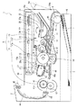
以下、本発明を具体化した画像形成装置およびプロセスカートリッジの一実施の形態について、図面を参照して説明する。まず、図1を参照して、画像形成装置の一例であるレーザプリンタ1の全体の構成について説明する。図1は、レーザプリンタ1の概略的な構成を示す模式図である。
【0021】
図1に示すように、レーザプリンタ1は、断面視、本体ケース2内に、被記録媒体としての用紙3を給紙するためのフィーダ部4や、給紙された用紙3に印刷するための画像形成部を構成するスキャナユニット16、プロセスカートリッジ17および定着器18等を備えている。なお、レーザプリンタ1において、図中右手方向が前面となる。また、用紙3の搬送経路を2点鎖線で示し、レーザ光の光路を1点鎖線で示す。
【0022】
排紙トレイ50は、本体ケース2の上面に設けられ、印刷された用紙3を積層保持する。この排紙トレイ50は略平面状に構成されている。また、本体ケース2の前面には、プロセスカートリッジ17の挿入のための一部開放状の空間があり、プロセスカートリッジ17は、本体ケース2の右端(前面側)のカバー54を、その支軸54aを支点として下向きに回動させて大きく開いた状態(図中点線で示す。)で着脱される。
【0023】
本体ケース2内の後部(図中左手側)には、本体ケース2内の下部後端側に設けられた定着器18から排出された用紙3が上方の排紙トレイ50に導かれるように、本体ケース2の背面に沿って上下方向に半弧状の搬送パス44が設けられ、この搬送パス44の用紙3の搬送方向末端に、用紙3の排紙トレイ50への排出を行う排紙ローラ45が設けられている。
【0024】
フィーダ部4は、本体ケース2内の底部に設けられた給紙ローラ8と、着脱可能に装着される給紙カセット6と、給紙カセット6内に設けられ、用紙3を積層保持して用紙3を給紙ローラ8に圧接する用紙3押圧板7と、給紙ローラ8により給紙される用紙3を搬送するための搬送パス46と、給紙ローラ8に対し用紙3の搬送方向の下流で画像形成部5の直前に設けられ、印刷の際に画像形成部5へ用紙3の送り出しのタイミングを調整するレジストローラ12,13とを備えている。なお、レジストローラ12は、後述するプロセスカートリッジ17に回転可能に支持され、レジストローラ13は、本体ケース2内にて回動可能に支持されている。
【0025】
用紙3押圧板7は、用紙3を積層状にスタックすることができ、給紙ローラ8に対して遠い方の端部が給紙カセット6の底面に回動可能に支持されており、近い方の端部が上下方向に移動可能となっている。また、その裏側から図示外のバネによって給紙ローラ8の方向に付勢されている。そのため、用紙3押圧板7は、用紙3の積層量が増えるにともない、バネの付勢力に抗して下向きに揺動される。
【0026】
次に、画像形成部のスキャナユニット16は、本体ケース2内において排紙トレイ50の直下に配置され、レーザ光を出射するレーザ光源19、レーザ光源19より出射されたレーザ光を回転駆動して主走査方向に走査するポリゴンミラー20、ポリゴンミラー20に走査されたレーザ光の走査速度を一定にするfθレンズ21、走査されたレーザ光を感光体ドラム27上で結像する際に、副走査方向における面倒れを補正するシリンダーレンズ22、シリンダーレンズ22を透過したレーザ光を感光体ドラム27に向けて反射する反射ミラー23から構成されている。スキャナユニット16は、印刷データに基づいてレーザ光源19から出射されるレーザ光を、図中1点鎖線で示すように、ポリゴンミラー20、fθレンズ21、シリンダーレンズ22、反射ミラー23の順に通過あるいは反射させて、プロセスカートリッジ17の感光体ドラム27の表面上に露光走査するものである。なお、スキャナユニット16が、本発明における「露光手段」に相当する。また、ポリゴンミラー20および反射ミラー23が、それぞれ、本発明における「走査手段」および「反射手段」に相当する。
【0027】
画像形成部の定着器18は、プロセスカートリッジ17の側方下流側に配設され、定着ローラ41、この定着ローラ41を押圧する加圧ローラ42、およびこれら定着ローラ41および加圧ローラ42の下流側に設けられる一対の搬送ローラ43を備えている。定着ローラ41は、中空のアルミ製の基材にフッ素樹脂がコーティングされ焼成されたローラであり、筒状のローラの内部に加熱のためのハロゲンランプ41aを備えている。加圧ローラ42は、低硬度シリコンゴムからなる基材にフッ素樹脂のチューブが被膜されたローラであり、スプリング(図示外)によってその軸が定着ローラ41の方向に付勢されることで、定着ローラ41に対して押圧されている。定着器18では、プロセスカートリッジ17において用紙3上に転写されたトナーを、用紙3が定着ローラ41と加圧ローラ42との間を通過する間に加圧加熱定着させ、その後、その用紙3を搬送ローラ43によって、搬送パス44に搬送するようにしている。
【0028】
次に、画像形成部のプロセスカートリッジ17は、ドラムカートリッジ17aと、ドラムカートリッジ17aに着脱可能な現像カートリッジ17bとから構成されている。ドラムカートリッジ17aは、感光体ドラム27、スコロトロン型の帯電器29を備えている。現像カートリッジ17bは、現像ローラ31、供給ローラ33、トナーホッパー34を備えている。
【0029】
ドラムカートリッジ17aの感光体ドラム27は、現像ローラ31と接触する状態で矢印方向(図中時計方向)に回転可能に配設されている。この感光体ドラム27は、導電性基材の上に、正帯電の有機感光体を塗布したものであり、電荷発生材料が電荷輸送層に分散された正帯電有機感光体である。感光体ドラム27はレーザ光等の照射を受けると、光吸収によって電荷発生材料で電荷が発生され、電荷輸送層で感光体ドラム27の表面と、導電性基材とにその電荷が輸送されて、帯電器29に帯電されたその表面電位をうち消すことで、照射を受けた部分の電位と、受けていない部分の電位との間に電位差を設けることができるようになっている。印刷データに基づいてレーザ光が露光走査されることにより、感光体ドラム27には静電潜像が形成されるのである。なお、感光体ドラム27が、本発明における「像担持体」に相当する。
【0030】
帯電手段としてのスコロトロン型の帯電器29は、本体ケース2の背面側の感光体ドラム27の側方に、感光体ドラム27に接触しないように所定の間隔を隔てて配設されている。帯電器29は、タングステンなどの放電用のワイヤ29aからコロナ放電を発生させるスコロトロン型の帯電器であり、グリッド電極29bによって放電電圧の安定化が図られている。感光体ドラム27の軸方向と平行にワイヤ29aが張設されており、ワイヤ29aおよびグリッド電極29bは、その周囲を上下から覆う2つのカバー29c,29dによって保護されている。グリッド電極29bは格子状の平面電極であり、その面方向が感光体ドラム27の接線方向と平行になるように配置されている。印刷時に帯電器29には帯電バイアスが印加され、感光体ドラム27の表面を一様に正極性に帯電させるように構成されている。なお、帯電器29が、本発明における「帯電手段」に相当する。
【0031】
また、現像カートリッジ17bがドラムカートリッジ17aに装着された状態では、現像ローラ31は、感光体ドラム27を挟んで帯電器29と反対側の感光体ドラムの側方の位置に配設されている。この位置は、感光体ドラム27の回転方向(図中時計方向)における帯電器29の下流にあたり、現像ローラ31は、矢印方向(図中反時計方向)に回転可能となるように、現像カートリッジ17bに支持されている。この現像ローラ31は、金属製のローラ軸に導電性のゴム材料からなるローラが被覆されており、印刷時には現像バイアスが印加される。なお、現像ローラ31が、本発明における「現像手段」に相当する。
【0032】
次に、供給ローラ33は、現像ローラ31の側方位置で、現像ローラ31を挟んで感光体ドラム27の反対側の位置に回転可能に配設されており、現像ローラ31に対して圧縮するような状態で当接されている。この供給ローラ33は、金属製のローラ軸に、導電性の発泡材料からなるローラが被覆されており、現像ローラ31に供給するトナーを摩擦帯電するようになっている。このため、供給ローラ33は、現像ローラ31と同方向となる矢印方向(図中反時計方向)に回転可能に配設されている。
【0033】
また、トナーホッパー34は、供給ローラ33の側方位置に設けられており、その内部に供給ローラ33を介して現像ローラ31に供給される現像剤を充填している。本実施の形態では、現像剤として正帯電性の非磁性1成分のトナーが使用されており、このトナーは、重合性単量体、例えばスチレンなどのスチレン系単量体やアクリル酸、アルキル(C1〜C4)アクリレート、アルキル(C1〜C4)メタアクリレートなどのアクリル系単量体を、懸濁重合などの公知の重合方法によって共重合させることにより得られる重合トナーである。このような重合トナーには、カーボンブラックなどの着色剤やワックスなどが配合されるとともに、流動性を向上させるために、シリカなど外添剤が添加されている。その粒子径は、約6〜10μm程度である。
【0034】
アジテータ36は軸方向(図中紙面表裏方向)に延設された粗い網目状の板体であり、一端から板面の直交方向に突設された支持部35の先端に回転軸35aが設けられ、他端にトナーホッパー34の内壁を摺擦するように構成されているフィルム部材36aが設けられている。そして、トナーホッパー34の長手方向の両端中心位置で回転軸35aが支持されたアジテータ36が矢印方向(図中時計方向)へ回転することによって、トナーホッパー34内に収容されたトナーが攪拌される。
【0035】
また、感光体ドラム27の回転方向の現像ローラ31の下流で、感光体ドラム27の下方位置には、転写ローラ30が配設されており、本体ケース2内で矢印方向(図中反時計方向)に回転可能に支持されている。この転写ローラ30は、金属製のローラ軸に、イオン導電性のゴム材料からなるローラが被覆されており、印刷時には転写バイアスが印加されるように構成されている。転写バイアスとは、感光体ドラム27の表面上に静電付着したトナーが転写ローラ30の表面上に電気的に吸引される方向に電位差が生じるように転写ローラ30に印加するバイアスである。なお、転写ローラ30が、本発明における「転写手段」に相当する。
【0036】
そして、レジストローラ12,13から送出される用紙3を感光体ドラム27と転写ローラ30とのニップ部へと導く搬送ガイド47と、感光体ドラム27と転写ローラ30とのニップ部を通過した用紙3を定着器18の定着ローラ41と加圧ローラ42とのニップ部へと導く搬送ガイド48とが設けられている。この搬送ガイド47,48は、その平面方向が、帯電器29、感光体ドラム27および現像ローラ31の配置方向に対して略平行となるように構成されている。各搬送ガイド47,48の上面には、用紙3の搬送方向に沿って延ばされたリブ状の突起47a,48aがそれぞれ複数設けられ、それぞれ用紙3の搬送方向と直交する方向に列設されている。なお、搬送ガイド47,48による用紙の搬送路が、本発明における「搬送路」に相当する。
【0037】
さらに、搬送ガイド48は帯電器29に対向しており、帯電器29の下側のカバー29dで、搬送ガイド48に対向する側の壁面に絶縁部材53が貼設されている。帯電器29と感光体ドラム27と現像ローラ31とは、その配置位置が略一列状に並ぶため、帯電器29は搬送ガイド48に対して近接することになる。帯電器29のワイヤ29aは、印刷時に約数千Vの高電圧が印加される(このとき、グリッド電極29bは約1000Vの電位に調整される。)ため、搬送ガイド48上を搬送される用紙3にこの電位による電気的な影響(例えば、用紙3が搬送中に丸まってしまうなど。)が及ばないように絶縁部材53が設けられている。
【0038】
また、感光体ドラム27の上方は、帯電器29と現像ローラ31とがそれぞれ相対する側方に配置されているため、大きく開放されている。この開放部分を保護するための保護部材49が、ドラムカートリッジ17aの筐体の上面に設けられている。保護部材49は感光体ドラム27の上方の開放部分を覆い隠す板状の部材であり、プロセスカートリッジ17が本体ケース2に装着された場合に、本体ケース2に固定されているスキャナユニット16から照射されるレーザ光の光路(図中1点鎖線で示す。)を塞がないように、板面を貫通する開口部49aが設けられている。この保護部材49により、プロセスカートリッジ17が本体ケース2から離脱された場合に、利用者が誤って触れたりすることや、印刷時以外で感光体ドラム27の表面が光に曝されることが防止されている。
【0039】
なお、レーザプリンタ1では、転写ローラ30によって感光体ドラム27から用紙3にトナーが転写された後に、感光体ドラム27の表面上に残存する転写残トナーを現像ローラ31で回収する、いわゆるクリーナレス現像方式を採用している。すなわち、クリーナレス現像方式では、転写後において、転写残トナーを有する感光体ドラム27の表面は、感光体ドラム27の回転により、帯電器29と対向する帯電位置にて帯電され、次に、スキャナユニット16によって露光される。露光されなかった未露光部分にある転写残トナーは、感光体ドラム27の表面が、現像ローラ31と対向したとき、電気的に現像ローラ31によって回収される。一方、露光部分では、転写残トナーと現像ローラ31からのトナーとによって、トナー像が形成される。
【0040】
このようなクリーナレス現像方式によれば、転写残トナーを回収して収容するための廃トナー貯留部を不要とすることができる。そのため、装置構成の簡略化、および、廃トナー貯留部を設けるスペースを不要として、プロセスカートリッジ17を薄型化できる。さらには、廃トナー貯留部をドラムカートリッジ17aに一体に設けた場合には、廃トナー貯留部の容量でドラムカートリッジ17aの寿命が決まってしまい、ドラムカートリッジ17aの長寿命化と装置の薄型化が達成できなくなるが、このように構成すれば、その両立を可能とすることができる。
【0041】
なお、本実施の形態では、現像ローラ31は、感光体ドラム27に対して1.6倍の周速で回転している。そして、その周速差によって、感光体ドラム27から現像ローラ31に転写残トナーを回収しやすくしている。
【0042】
また、このレーザプリンタ1では、トナーとして、流動性の良好な略球形の重合トナーを用いているので、良好な画像を形成しつつ、クリーナレス現像方式による転写残トナーの効率的な回収を達成している。
【0043】
次に、図1を参照して、レーザプリンタ1の印刷時の動作について説明する。レーザプリンタ1では、ホストコンピュータ(図示外)からの印刷データの受信に基づいて、駆動モータ(図示外)が駆動される。図1に示すように、用紙3は、回転する給紙ローラ8との間の摩擦力によってピックアップされ、レジストローラ12,13に送られる。そして、レジストローラ12,13は用紙3をレジストし、回転する感光体ドラム27の表面上に形成された可視像の先端と用紙3の先端とが一致するタイミングで用紙3を送り出す。
【0044】
一方、スキャナユニット16では、印刷データに基づいて生成されたレーザ駆動信号に従ってレーザ光源19でレーザ光が発生され、ポリゴンミラー20に対して出射される。ポリゴンミラー20は入射したレーザ光を主走査方向(用紙3の搬送方向と直交する方向)に走査し、fθレンズ21に対して出射する。fθレンズ21は、ポリゴンミラー20で等角速度に走査されたレーザ光を等速度走査に変換する。そして、レーザ光はシリンダーレンズ22によって収束され、反射ミラー23で反射されて感光体ドラム27の表面上にて結像される。
【0045】
また、感光体ドラム27は、高圧電源部(図示外)より帯電バイアスが印加された帯電器29によって、その表面電位が約1000Vに帯電される。図中時計方向に回転する感光体ドラム27は、次に、レーザ光の照射を受ける。レーザ光は用紙3の主走査線上において、現像を行う部分には照射され、行わない部分には照射されないようにスキャナユニット16から出射されており、レーザ光の照射を受けた部分(明部)は、その表面電位が約200Vに下がる。そして、感光体ドラム27の回転にともなって、レーザ光が副走査方向(用紙3の搬送方向)にも照射され、レーザ光が照射されなかった部分(暗部)と明部とで、感光体ドラム27表面上には電気的な不可視画像、すなわち静電潜像が形成される。
【0046】
ここで、トナーホッパー34より供給され、供給ローラ33と現像ローラ31との間で正に摩擦帯電されたトナーは、厚みが一定の薄層となるように調整されて現像ローラ31上に担持される。この現像ローラ31には、高圧電源部(図示外)より約400Vの正の現像バイアスが印加されている。現像ローラ31の回転により、現像ローラ31上に担持され、かつ、正帯電されているトナーは、感光体ドラム27に対向して接触するときに、感光体ドラム27の表面上に形成されている静電潜像に転移する。すなわち、現像ローラ31の電位は、暗部の電位(+1000V)より低く、明部の電位(+200V)より高いので、トナーは電位の低い明部に対して選択的に転移する。こうして、感光体ドラム27の表面上に、トナーによる現像剤像としての可視像が形成され、現像が行われる。
【0047】
そして、感光体ドラム27と転写ローラ30との間を用紙3が通過する際に、明部の電位(+200V)よりさらに低い、(電圧値にして)約−1000Vの負の定電流である転写バイアスが転写ローラ30に印加されて、感光体ドラム27表面上に形成された可視像が用紙3上に転写される。
【0048】
トナーが転写された用紙3は、定着器18に搬送される。定着器18は、トナーの載った用紙3に、定着ローラ41による約200℃の熱と加圧ローラ42による圧力とを加え、トナーを用紙3上に溶着させて永久画像を形成する。なお、定着ローラ41と加圧ローラ42とはそれぞれダイオードを介して接地されており、定着ローラ41の表面電位より加圧ローラ42の表面電位が低くなるように構成されている。そのため、用紙3の定着ローラ41側に載置されている正帯電性のトナーは、用紙3を介して加圧ローラ42に電気的に吸引されるので、定着時に定着ローラ41にトナーが引き寄せられることによる画像の乱れが防止されている。
【0049】
トナーが加圧加熱定着された用紙3は搬送パス44上を搬送され、排紙ローラ45により印刷面を下向きにして排紙トレイ50に排出される。次に印刷される用紙3も同様に、先に排出された用紙3の上に印刷面を下にして排紙トレイ50に積層される。こうして、利用者は、印刷順に整列された用紙3を得ることができる。
【0050】
上述したように、本実施の形態のレーザプリンタ1では、感光体ドラム27の表面に対し、帯電器29、現像ローラ31、および転写ローラ30が対向して配置される。さらに、感光体ドラム27の表面にはレーザ光の照射を受ける部分もあり、感光体ドラム27を中心としたこれらの各対向部分の配置関係は、レーザプリンタ1の小型化を図る上で、図2に示す条件に沿って決められている。図2は、感光体ドラム27と、その周囲に配置される部材等との関係を示す図である。
【0051】
図2に示すように、感光体ドラム27の軸と直交する断面を4等分して、その外周、すなわち感光体ドラム27の表面を4つの区画に分けた場合、上下方向をレーザプリンタ1の上面底面方向、左右方向がレーザプリンタ1の背面前面方向として、右側面から順に区画I、区画II、区画III、区画IVとする。また、本発明におけるプロセス手段とは、画像形成を行うために感光体ドラム27に対して作用する部材、例えば、本実施例の現像ローラ31、転写ローラ30、帯電器29や、感光体ドラム27のクリーニングを行うためのクリーニング部材(例えばクリーニングブレード、クリーニングブラシ、クリーニングローラなど)等の部材をいう。なお、区画I,II,III,IVが、それぞれ、本発明における「第1の領域」,「第2の領域」,「第3の領域」,「第4の領域」に相当する。
【0052】
区画Iには、現像ローラ31の作用する領域が配置される。現像ローラ31の作用する領域は、感光体ドラム27の表面の静電潜像に現像ローラ31の担持したトナーが転写されて現像される領域であり、ニップ部の感光体ドラム27の回転方向における中心位置がその作用中心Aとなる。感光体ドラム27と現像ローラ31とは、接触・非接触を問わないが、感光体ドラム27の軸27aと、現像ローラ31の軸31aとを結ぶ直線における感光体ドラム27の表面と交差する位置が現像ローラ31の作用中心Aとなり、その作用中心Aが、少なくとも区画I内に存在する。
【0053】
区画IIについても同様に、転写ローラ30の作用する領域、すなわち感光体ドラム27と転写ローラ30とのニップ部が配置される。軸27aと転写ローラ30の軸30aとを結ぶ直線における感光体ドラム27の表面と交差する位置が転写ローラ30の作用中心Bであり、その作用中心Bが、少なくとも区画II内に存在する。
【0054】
区画IIIには、帯電器29の作用する領域が配置される。帯電器29は、上述したように、グリッド電極29bによってワイヤ29aからの放電電圧の安定化が図られており、その作用する領域は、グリッド電極29bの面が感光体ドラム27の表面に対向する範囲Tである。この範囲Tの感光体ドラム27の回転方向における中心位置が、帯電器29の作用中心Cとなる。このとき、グリッド電極29bの面方向は感光体ドラム27の表面の接線方向と平行となる。帯電器29による感光体ドラム27の表面の帯電は範囲Tの全体において行われるため、ワイヤ29aと軸27aとを結んだ直線における感光体ドラム27の表面と交差する位置が、本実施例では感光体ドラム27に対する帯電器29の作用中心Cとみなすことができる。そして、少なくとも区画III内に、作用中心Cが存在する。
【0055】
従って、区画IVには、プロセス手段、すなわち現像ローラ31、転写ローラ30、帯電器29のいずれも配置されない。しかし、この区画IV内にて、感光体ドラム27の上方に配置されるスキャナユニット16(図1参照)から出射されるレーザ光が照射される。換言すれば、スキャナユニット16のレーザ光は、区画IV内に照射されればよく、スキャナユニット16からのレーザ光の出射位置の自由度が高い。
【0056】
このように、それぞれの部材等の作用する領域が配置され、特に、感光体ドラム27に対し、帯電器29の作用する領域と現像ローラ31の作用する領域とは、互いに反対側となる区画III内と区画I内とに存在する。このため、図1に示すように、帯電器29と感光体ドラム27と現像ローラ31とが略一列状に並ぶ配置となる。よって、ドラムカートリッジ17aを構成する帯電器29と感光体ドラム27との配置関係を、レーザプリンタ1に対して略水平方向の配置となるので、ドラムカートリッジ17aの厚みを薄くすることができる。
【0057】
これにより、本体ケース2内における感光体ドラム27とスキャナユニット16との間の配置距離を近づけることができる。上記のように、スキャナユニット16からのレーザ光の出射位置の自由度を高くすることができるので、スキャナユニット16と感光体ドラム27との配置距離が近づいても、スキャナユニット16から出射されるレーザ光を感光体ドラム27の区画IV内に納めることが十分可能である。さらに、スキャナユニット16からのレーザ光の出射位置の自由度を高くしたことで、レーザ光源19から出射されポリゴンミラー20で走査されるレーザ光がスキャナユニット16から出射される位置までに必要となる距離を、スキャナユニット16内の平面内で確保することが可能となる。すなわち、スキャナユニット16を構成する部品の配置の自由度が高くなるので、スキャナユニット16内部でレーザ光の光路を複数回折り返さなくても十分なレーザ光の光路長を確保することができる。レーザプリンタ1では、スキャナユニット16内におけるレーザ光の光路がほぼ平面内に収まるようにし、反射ミラー23の反射によって角度を変えてスキャナユニット16から出射することで、光路変更が1回で済み、スキャナユニット16の薄型化を実現している。また、排紙トレイ50を平面状に構成しているので、この排紙トレイ50の平面と、その直下に配設されるスキャナユニット16の上面と、レーザ光の光路がなす平面とをそれぞれ略平行に構成したことにより、本体ケース2内の無駄な空間を省いている。
【0058】
そして、上記した帯電器29の作用中心Cと現像ローラ31の作用中心Aとを結ぶ方向Xをプロセスカートリッジ17の着脱方向とし、スキャナユニット16がプロセスカートリッジ17の着脱に干渉しないように、スキャナユニット16の筐体の底面をプロセスカートリッジ17の着脱方向と略平行にしている。また、現像カートリッジ17bのトナーホッパー34の上面は、スキャナユニット16の筐体の底面に沿って平行に設けられている。これにより、プロセスカートリッジ17の着脱をその着脱方向に直線的に行うことができるので、本体ケース2内のプロセスカートリッジ17の着脱のための空間を省くことができる。さらに、プロセスカートリッジ17の収容空間にてプロセス手段等の必須部品が占める空間を除く空き空間をトナーホッパー34として最大に利用することができるので、本体ケース2内の空間を小さくしたにもかかわらず、収容するトナーの量を増やすことができる。
【0059】
また、搬送ガイド47,48の平面方向が、帯電器29の作用中心Cと現像ローラ31の作用中心Aとを結ぶ方向Xに略平行となるように設けられており、すなわち、搬送ガイド47,48上を搬送される用紙3の搬送方向は、プロセスカートリッジ17の着脱方向、さらにはスキャナユニット16の底面の面方向や排紙トレイ50の平面方向にそれぞれ略平行となるので、本体ケース2内の空間を有効に利用できる。
【0060】
レーザプリンタ1は上記のような構成であるので、本体ケース2の厚み方向における大きさを小さくすることができ、薄型化を実現できる。これにより、例えばレーザプリンタ1の上方に画像読取装置などを配置した複合機を設計した場合でも、装置全体の大きさをコンパクトにすることが可能である。
【0061】
以上説明したように、本実施の形態のレーザプリンタ1は、帯電器29と感光体ドラム27と現像ローラ31とが略一列状に並ぶ配置としたので、感光体ドラム27の上方にはプロセス手段のいずれも配置されないので、スキャナユニット16を感光体ドラム27に近づけて配置することができる。さらに、感光体ドラム27の表面における上側の領域には、近接して作用する部材が配置されないので、スキャナユニット16から出射されるレーザ光の照射可能な範囲を広くとることができ、スキャナユニット16を構成する部品の配置の自由度が高められ、スキャナユニット16の薄型化を実現することができる。
【0062】
また、帯電器29と感光体ドラム27と現像ローラ31とが略一列状に並ぶ配置としたので、プロセスカートリッジ17の薄型化を実現できる。さらに、プロセスカートリッジ17の着脱方向にスキャナユニット16が干渉しないように、プロセスカートリッジ17の上面をスキャナユニット16の筐体の底面と略平行に設けている。これにより、本体ケース2の薄型化を実現しつつ、プロセスカートリッジ17の着脱を可能としている。
【0063】
また、帯電器29の搬送ガイド48に対向する側のカバー29dの壁面に絶縁部材53を設けたので、帯電器29が搬送ガイド48に近づいて配置されたことによる搬送ガイド48上を搬送される用紙3への電気的な影響は及ばない。また、感光体ドラム27の上方を覆うように保護部材49を設けたので、プロセスカートリッジ17の着脱の際に利用者が誤って感光体ドラム27の表面に触れることがない。また、印刷時以外に感光体ドラム27の表面が光に曝されることを防止している。
【0064】
なお、本発明は、各種の変形が可能なことはいうまでもない。例えば、転写ローラ30をドラムカートリッジ17aに収容して、感光体ドラム27、帯電器29とともに一体に構成してもよい。また、帯電器29のワイヤ29aは2本以上設けられてもよい。また、プロセスカートリッジ17の着脱方向は、レーザプリンタ1の左右方向(図1中紙面表裏方向)であってもよく、スキャナユニット16の筐体の壁面に沿った方向に着脱されればよい。
【0065】
【発明の効果】
以上説明したように、請求項1に係る発明の画像形成装置では、帯電手段と像担持体と現像手段とを露光手段の筐体と略平行に配置できるので、露光手段を像担持体に近づけて配置することができ、画像形成装置の高さ方向の厚みを薄くすることができる。
【0066】
また、請求項2に係る発明の画像形成装置では、請求項1に係る発明の効果に加え、像担持体の回転方向において、帯電手段が作用する領域の下流側で、現像手段が作用する領域の上流側であれば、露光手段を像担持体に近づけて配置することができるので、画像形成装置の高さ方向の厚みを薄くすることができる。
【0067】
また、請求項3に係る発明の画像形成装置では、請求項1または2に係る発明の効果に加え、像担持体の露光手段側の外周面が、レーザ光を遮断しない開口部が開口された保護部材で覆われて保護されているので、像担持体の傷付きや画像形成装置内に侵入した光による露光を防止することができる。
【0068】
また、請求項4に係る発明の画像形成装置では、請求項1乃至3のいずれかに係る発明の効果に加え、プロセスカートリッジの着脱方向を帯電手段と現像手段との配列方向に沿わせることで、画像形成装置の高さ方向の厚みを薄くしても、着脱を行うことができる。
【0069】
また、請求項5に係る発明の画像形成装置では、請求項1乃至4のいずれかに係る発明の効果に加え、被記録媒体の搬送方向が帯電手段と現像手段との配列方向と略平行であるので、画像形成装置の高さ方向の厚みを薄くすることができる。
【0070】
また、請求項6に係る発明の画像形成装置では、請求項1乃至5のいずれかに係る発明の効果に加え、帯電手段と現像手段とが露光手段の筐体に対して略平行に配置されているので、像担持体の露光可能な領域を広くすることができ、露光手段から出射されるレーザ光の光路の向きの自由度が高まる。このため、露光手段の構成する部材の配置の自由度を高められ、レーザ光の光路を長く取ることができるので反射手段によるレーザ光の反射を1回で済ませることができ、露光手段を厚み方向に薄くすることができる。
【0071】
また、請求項7に係る発明の画像形成装置では、請求項5または6に係る発明の効果に加え、帯電手段と搬送路との間に絶縁部材が設けられているので、搬送路を搬送される被記録媒体に電気的な影響を与えないので、現像剤像の転写後の被記録媒体の挙動を安定させることができる。
【0072】
また、請求項8に係る発明の画像形成装置では、請求項1乃至7のいずれかに係る発明の効果に加え、現像手段の着脱を可能にしつつ、現像手段の筐体を大きくすることができ、現像剤の収容部分を大きくとることができる。
【0073】
また、請求項9に係る発明の画像形成装置では、帯電手段と現像手段とが像担持体の回転中心を挟んで相対する領域に配置され、像担持体における帯電手段と現像手段との間の領域にプロセス手段を近接配置しないので、露光手段を像担持体に近づけて配置することができ、画像形成装置の高さ方向の厚みを薄くすることができる。
【0074】
また、請求項10に係る発明の画像形成装置では、請求項1乃至9のいずれかに係る発明の効果に加え、現像剤像が被記録媒体に転写された後に、像担持体上に残存する現像剤が現像手段によって回収されるので、像担持体上に残存する現像剤を回収するための貯留手段を設ける必要がなく、装置構成の簡易化および装置の薄型化を図ることができる。そのため、帯電手段を上記のような位置に配置することができる。
【0075】
また、請求項11に係る発明のプロセスカートリッジでは、帯電手段と現像手段とが像担持体を挟んで略反対側の位置にそれぞれ配置されるので、露光手段を像担持体に近づけて配置することが可能となり、画像形成装置の高さ方向の厚みを薄くすることが可能になる。
【0076】
また、請求項12に係る発明のプロセスカートリッジでは、請求項11に係る発明の効果に加え、プロセスカートリッジの着脱方向を帯電手段と現像手段との配列方向に沿わせることで、露光手段に干渉することなくプロセスカートリッジの着脱を行うことが可能となる。
【0077】
また、請求項13に係る発明のプロセスカートリッジでは、帯電手段と現像手段とが像担持体の回転中心を挟んで相対する領域に配置され、像担持体における帯電手段と現像手段との間の領域にプロセス手段を近接配置しないので、画像形成装置に装着されたときに、露光手段を像担持体に近づけて配置することが可能となり、画像形成装置の高さ方向の厚みを薄くすることが可能になる。
【図面の簡単な説明】
【図1】レーザプリンタ1の概略的な構成を示す模式図である。
【図2】感光体ドラム27と、その周囲に配置される部材等との関係を示す図である。
【符号の説明】
1 レーザプリンタ
16 スキャナユニット
17 プロセスカートリッジ
19 レーザ光源
20 ポリゴンミラー
23 反射ミラー
27 感光体ドラム
29 帯電器
30 転写ローラ
31 現像ローラ
47 搬送パス
48 搬送パス
49 保護部材
49a 開口部
53 絶縁部材[0001]
TECHNICAL FIELD OF THE INVENTION
The present invention relates to an image forming apparatus and a process cartridge in which a charging unit, an image carrier, and a developing unit are arranged substantially in a line.
[0002]
[Prior art]
2. Description of the Related Art Conventionally, in an electrophotographic image forming apparatus such as a laser printer or a copying machine, a charging device (image carrier) is provided on a surface of a photosensitive drum (image carrier) in which a charge generation layer and a charge transport layer are laminated on a base material layer. Charging by corona discharge from the charging means) is performed, and exposure using laser light is performed on the photosensitive drum by the scanner unit (exposure means). The electrostatic latent image formed by the exposure is visualized by a developer such as toner carried on a developing roller (developer carrier) to form a developer image, and the developer image is formed on paper or the like. After the image is transferred onto the recording medium by a transfer roller (transfer means) and then heat-fixed, an image is formed.
[0003]
In the image forming apparatus having such a configuration, in order to realize the above-described image forming process, a charger, a developing roller, and a transfer roller are arranged in order from the upstream in the rotation direction along the periphery of the photosensitive drum. And so on. Further, the photosensitive drum is irradiated with laser light from the scanner unit at an outer peripheral portion between the charger and the developing roller. Since there are many members and the like to be arranged around the photoconductor drum in this way, for example, in Patent Document 1, a charger is provided at a position above the photoconductor drum, and a portion irradiated with laser light by a scanner unit at a position immediately downstream of the charger. The developing roller and the transfer roller are arranged further downstream and on the side of the photosensitive drum, respectively, so that the space around the photosensitive drum is reduced, and efficient members such as members are reduced. The arrangement has been realized.
[0004]
[Patent Document 1]
JP 2000-250378 A
[0005]
[Problems to be solved by the invention]
However, since the charger is disposed above the photoconductor drum, the thickness of the image forming apparatus increases, which is an adverse effect of reducing the thickness of the image forming apparatus, and furthermore, the surface of the photoconductor drum is irradiated with laser light. Is limited to a limited range further downstream of the charger, so that the emission position of the laser beam is limited, and it is difficult to reduce the thickness of the scanner unit, and as a result, it is difficult to reduce the thickness of the image forming apparatus. There was a problem that.
[0006]
SUMMARY An advantage of some aspects of the invention is to provide an image forming apparatus and a process cartridge that can be reduced in thickness.
[0007]
[Means for Solving the Problems]
In order to achieve the above object, an image forming apparatus according to the first aspect of the present invention comprises an image carrier on which an electrostatic latent image is formed rotatably held, and a charging device for charging the image carrier. Means, exposure means for exposing the image carrier to form an electrostatic latent image on the image carrier charged by the charging means, and electrostatic latent of the image carrier formed by the exposure means. An image forming apparatus comprising: a developing unit configured to develop an image by using a developer to form a developer image, wherein when the charging unit charges the image carrier, an outer peripheral surface of the image carrier is used. And a charging operation center, which is a center position in the rotation direction of the image carrier in an area where the charging device operates, and an outer peripheral surface of the image carrier when the developing device develops the image carrier. The image carrier rotation direction in the area where the developing means operates The developing action center, which is the center position in the image carrier, is disposed at a position substantially opposite to the rotation center of the image carrier, and the direction connecting the charging action center and the developing action center is the exposure direction. It is configured to be substantially parallel to the housing of the means.
[0008]
According to a second aspect of the present invention, in the image forming apparatus according to the first aspect of the invention, in the rotation direction of the image carrier, the developing unit is disposed downstream of an area where the charging unit operates. It is characterized in that a process means acting in close proximity to the image bearing member is not arranged on the upstream side of the area where the image acts.
[0009]
According to a third aspect of the present invention, in the image forming apparatus according to the first or second aspect, the charging unit on the outer peripheral surface of the image bearing member on the side of the exposure unit may be configured such that the charging unit is provided with the image bearing member. A protection member for covering and protecting a region between an area acting on the outer peripheral surface and an area where the developing means acts on the outer peripheral surface of the image carrier; And an opening for allowing the laser light emitted from the means to pass therethrough.
[0010]
According to a fourth aspect of the present invention, in addition to the configuration of the first aspect of the present invention, the image forming apparatus further comprises a process cartridge which houses at least the image carrier and is detachably provided. The process cartridge is detachably mounted along a direction connecting the charging operation center and the developing operation center.
[0011]
According to a fifth aspect of the present invention, there is provided the image forming apparatus according to any one of the first to fourth aspects, further comprising a transfer unit configured to transfer the developer image on the image carrier to a recording medium. And a transport path for transporting a recording medium passing between the image carrier and the transfer unit, the transport direction of the recording medium transported through the transport path, the charging action center and It is characterized by being substantially parallel to the direction connecting the developing action center.
[0012]
According to a sixth aspect of the present invention, in the image forming apparatus according to the first aspect of the invention, the exposing unit includes a scanning unit that scans a laser beam emitted from a laser light source. A reflecting unit that is disposed closer to the charging operation center in a direction connecting the charging operation center and the developing operation center than the center of the housing, and reflects laser light scanned by the scanning unit, In the optical path from when the laser light emitted from the laser light source is scanned by the scanning means to when the laser beam is exposed on the image carrier, the traveling direction of the laser light is changed only once by the reflection means. It is characterized by the following.
[0013]
An image forming apparatus according to a seventh aspect of the present invention is the image forming apparatus according to the fifth or sixth aspect, wherein the charging unit is a recording medium that passes between the image carrier and the transfer unit. In the conveyance direction, an insulating member is provided between the conveyance path and the charging unit, and is disposed downstream of the image carrier.
[0014]
According to an eighth aspect of the present invention, in addition to the configuration of the first aspect, the housing of the developing unit is substantially parallel to the housing of the exposure unit. It is configured so that
[0015]
An image forming apparatus according to a ninth aspect of the present invention is an image forming apparatus which is rotatably held and on which an electrostatic latent image is formed, a charging unit for charging the image carrier, and the charging unit. Exposure means for exposing the image carrier to form an electrostatic latent image on the image carrier charged by the method, and developing the electrostatic latent image of the image carrier formed by the exposure means with a developer An image forming apparatus comprising: a developing unit for forming a developer image by using the developing unit; and a transfer unit for transferring a developer image of the image carrier formed by the developing unit to a recording medium. When the outer peripheral surface of the image carrier is equally divided into four regions of a first region, a second region, a third region, and a fourth region in the rotation direction, the first region is formed. In the area, an area where the developing means operates is arranged, and in the second area, An area on which a transfer unit operates is disposed, and the third area is an area opposed to the first area with the rotation center of the image carrier interposed therebetween, and in the third area, A region in which the charging means operates is disposed, and the fourth region is a region opposed to the second region with the rotation center of the image carrier interposed therebetween. It is a region where no means is arranged.
[0016]
According to a tenth aspect of the present invention, in the image forming apparatus according to the first aspect, the developer image carried on the image carrier is transferred to a recording medium. Later, the developer remaining on the image carrier is recovered by the developing unit.
[0017]
Further, the process cartridge of the invention according to claim 11 is an image carrier that is rotatably held and on which an electrostatic latent image is formed, and the image carrier for forming an electrostatic latent image on the image carrier. A developing means for housing a charging means for charging the body, detachable from the image forming apparatus, and developing the electrostatic latent image formed on the image carrier to form a developer image; A process cartridge disposed opposite to the image carrier, wherein when the charging unit charges the image carrier, the image carrier in an area where the charging unit acts on an outer peripheral surface of the image carrier. A charging operation center that is a center position in a rotation direction, and rotation of the image carrier in a region where the developing unit acts on an outer peripheral surface of the image carrier when the developing unit develops the image carrier. Developing center which is the center position in the direction But characterized in that it is arranged at a position substantially opposite side of the center of rotation of said image bearing member.
[0018]
According to a twelfth aspect of the present invention, in addition to the configuration of the eleventh aspect, the process cartridge according to the twelfth aspect is characterized in that the process cartridge is attached and detached substantially parallel to a direction connecting the charging operation center and the developing operation center. .
[0019]
A process cartridge according to a thirteenth aspect of the present invention includes an image carrier that is rotatably held and on which an electrostatic latent image is formed, a charging unit for charging the image carrier, and the charging unit. Developing means for developing a charged electrostatic latent image formed on the image carrier with a developer to form a developer image; and developing the developer image on the image carrier formed by the developing means. A process cartridge removably provided in an image forming apparatus having a transfer unit for transferring the image on a recording medium, the process cartridge containing at least the image carrier and the charging unit, and an outer periphery of the image carrier. When the surface is equally divided into four regions of a first region, a second region, a third region, and a fourth region in the rotation direction, the developing unit is provided in the first region. Is disposed, and the second An area in which the transfer unit operates is disposed in the area, and the third area is an area opposed to the first area with the rotation center of the image carrier interposed therebetween, and An area in which the charging unit operates is disposed in the area, and the fourth area is an area opposed to the second area with the rotation center of the image carrier interposed therebetween, and is opposed to the second area. This is a region in which the process means that acts is not disposed.
[0020]
BEST MODE FOR CARRYING OUT THE INVENTION
Hereinafter, an embodiment of an image forming apparatus and a process cartridge embodying the present invention will be described with reference to the drawings. First, an overall configuration of a laser printer 1 as an example of an image forming apparatus will be described with reference to FIG. FIG. 1 is a schematic diagram illustrating a schematic configuration of the laser printer 1.
[0021]
As shown in FIG. 1, a laser printer 1 includes a feeder unit 4 for feeding paper 3 as a recording medium in a main body case 2 in a cross-sectional view, and a laser printer 1 for printing on the fed paper 3. The image forming section includes a
[0022]
The
[0023]
A paper 3 discharged from a fixing
[0024]
The feeder unit 4 includes a paper feed roller 8 provided at the bottom in the main body case 2, a paper feed cassette 6 that is detachably mounted, and a paper feed cassette 6 that is provided inside the paper feed cassette 6 and holds and stacks the paper 3. 3, a paper 3 pressing plate 7 for pressing the paper 3 against the paper feed roller 8, a
[0025]
The paper 3 pressing plate 7 is capable of stacking the paper 3 in a stacked manner, and has an end remote from the paper feed roller 8 rotatably supported on the bottom surface of the paper feed cassette 6, Is vertically movable. Further, it is urged in the direction of the paper feed roller 8 from the back side by a spring (not shown). Therefore, the sheet 3 pressing plate 7 is swung downward against the urging force of the spring as the amount of stacked sheets 3 increases.
[0026]
Next, the
[0027]
The fixing
[0028]
Next, the
[0029]
The
[0030]
A scorotron-
[0031]
When the developing
[0032]
Next, the
[0033]
Further, the
[0034]
The
[0035]
Further, a
[0036]
Then, a
[0037]
Further, the
[0038]
Above the
[0039]
In the laser printer 1, after the toner is transferred from the
[0040]
According to such a cleanerless developing method, a waste toner storing section for collecting and storing the transfer residual toner can be eliminated. For this reason, the
[0041]
In the present embodiment, the developing
[0042]
Further, in the laser printer 1, since a substantially spherical polymerized toner having good fluidity is used as the toner, an efficient recovery of the transfer residual toner by the cleanerless developing method is achieved while forming a good image. are doing.
[0043]
Next, the operation of the laser printer 1 during printing will be described with reference to FIG. In the laser printer 1, a drive motor (not shown) is driven based on reception of print data from a host computer (not shown). As shown in FIG. 1, the paper 3 is picked up by frictional force between the paper 3 and the rotating paper feed roller 8 and sent to
[0044]
On the other hand, in the
[0045]
The surface potential of the
[0046]
Here, the toner supplied from the
[0047]
When the paper 3 passes between the
[0048]
The sheet 3 onto which the toner has been transferred is conveyed to the fixing
[0049]
The sheet 3 on which the toner is heated and fixed by pressure is conveyed on a conveying
[0050]
As described above, in the laser printer 1 of the present embodiment, the
[0051]
As shown in FIG. 2, when the cross section orthogonal to the axis of the
[0052]
In the section I, an area where the developing
[0053]
Similarly, in the section II, a region where the
[0054]
In the section III, an area where the
[0055]
Accordingly, none of the processing means, that is, none of the developing
[0056]
In this way, the areas where the respective members and the like act are arranged, and in particular, the area where the
[0057]
Thereby, the arrangement distance between the
[0058]
The direction X connecting the operation center C of the
[0059]
Further, the transport guides 47 and 48 are provided so that the plane direction thereof is substantially parallel to the direction X connecting the operation center C of the
[0060]
Since the laser printer 1 has the above-described configuration, the size of the main body case 2 in the thickness direction can be reduced, and the thickness can be reduced. Thus, for example, even when a multifunction device in which an image reading device or the like is arranged above the laser printer 1 is designed, the size of the entire device can be reduced.
[0061]
As described above, in the laser printer 1 according to the present embodiment, the
[0062]
Further, since the
[0063]
In addition, since the insulating
[0064]
It goes without saying that the present invention can be variously modified. For example, the
[0065]
【The invention's effect】
As described above, in the image forming apparatus according to the first aspect of the present invention, the charging unit, the image carrier, and the developing unit can be disposed substantially parallel to the housing of the exposure unit. And the thickness of the image forming apparatus in the height direction can be reduced.
[0066]
Further, in the image forming apparatus according to the second aspect of the invention, in addition to the effects of the first aspect, in the rotation direction of the image carrier, a region downstream of the region where the charging unit operates and a region where the developing unit operates. On the upstream side of the image forming apparatus, the exposing means can be arranged close to the image carrier, so that the thickness of the image forming apparatus in the height direction can be reduced.
[0067]
In the image forming apparatus according to the third aspect of the present invention, in addition to the effects of the first or second aspect, the outer peripheral surface of the image carrier on the side of the exposure unit has an opening that does not block laser light. Since the image carrier is covered and protected by the protection member, it is possible to prevent the image carrier from being scratched and from being exposed to light that has entered the image forming apparatus.
[0068]
Further, in the image forming apparatus according to the fourth aspect of the present invention, in addition to the effects of the first aspect of the present invention, the mounting / removing direction of the process cartridge is set along the arrangement direction of the charging unit and the developing unit. Even when the thickness of the image forming apparatus in the height direction is reduced, the image forming apparatus can be attached and detached.
[0069]
Further, in the image forming apparatus according to the fifth aspect of the invention, in addition to the effects of the first aspect, the transport direction of the recording medium is substantially parallel to the arrangement direction of the charging unit and the developing unit. Therefore, the thickness of the image forming apparatus in the height direction can be reduced.
[0070]
Further, in the image forming apparatus according to the sixth aspect, in addition to the effects of the first aspect, the charging unit and the developing unit are disposed substantially parallel to the housing of the exposure unit. Accordingly, the area of the image carrier that can be exposed can be widened, and the degree of freedom of the direction of the optical path of the laser beam emitted from the exposure unit increases. For this reason, the degree of freedom of the arrangement of the members constituting the exposure means can be increased, and the optical path of the laser light can be long, so that the reflection of the laser light by the reflection means can be performed only once, and the exposure means can be moved in the thickness direction. Can be made thinner.
[0071]
Further, in the image forming apparatus according to the seventh aspect of the invention, in addition to the effects of the fifth or sixth aspect, since the insulating member is provided between the charging unit and the transport path, the image is transported along the transport path. Since no electrical influence is exerted on the recording medium, the behavior of the recording medium after the transfer of the developer image can be stabilized.
[0072]
Further, in the image forming apparatus according to the eighth aspect of the present invention, in addition to the effects of the first aspect of the present invention, it is possible to increase the size of the housing of the developing unit while enabling the mounting and dismounting of the developing unit. In addition, it is possible to increase the size of the housing portion of the developer.
[0073]
Further, in the image forming apparatus according to the ninth aspect, the charging unit and the developing unit are disposed in a region opposed to each other with the rotation center of the image carrier therebetween, and the charging unit and the developing unit in the image carrier are disposed between the charging unit and the developing unit. Since the process means is not arranged close to the area, the exposure means can be arranged close to the image carrier, and the thickness of the image forming apparatus in the height direction can be reduced.
[0074]
Further, in the image forming apparatus according to the tenth aspect, in addition to the effects of the first aspect, the developer image remains on the image carrier after being transferred to the recording medium. Since the developer is collected by the developing means, there is no need to provide a storage means for collecting the developer remaining on the image carrier, and the apparatus configuration can be simplified and the apparatus can be made thinner. Therefore, the charging unit can be arranged at the position as described above.
[0075]
In the process cartridge according to the eleventh aspect of the present invention, the charging means and the developing means are respectively disposed at positions substantially opposite to each other across the image carrier, so that the exposing means is arranged close to the image carrier. And the thickness of the image forming apparatus in the height direction can be reduced.
[0076]
Further, in the process cartridge according to the twelfth aspect, in addition to the effects of the eleventh aspect, the process cartridge is attached and detached along the direction in which the charging means and the developing means are arranged, thereby causing interference with the exposure means. The process cartridge can be attached and detached without the need.
[0077]
Further, in the process cartridge according to the present invention, the charging means and the developing means are arranged in a region opposed to each other with the rotation center of the image carrier therebetween, and a region between the charging means and the developing device in the image carrier is provided. Since the process means is not arranged close to the image forming apparatus, the exposure means can be arranged close to the image carrier when the image forming apparatus is mounted on the image forming apparatus, and the thickness of the image forming apparatus in the height direction can be reduced. become.
[Brief description of the drawings]
FIG. 1 is a schematic diagram showing a schematic configuration of a laser printer 1. FIG.
FIG. 2 is a diagram illustrating a relationship between a
[Explanation of symbols]
1 Laser printer
16 Scanner unit
17 Process cartridge
19 Laser light source
20 polygon mirror
23 Reflection mirror
27 Photoconductor drum
29 Charger
30 Transfer roller
31 Developing roller
47 Transport Path
48 transport path
49 Protective member
49a opening
53 Insulation member
Claims (13)
前記帯電手段が前記像担持体を帯電する場合に、前記像担持体の外周面に対して前記帯電手段が作用する領域の前記像担持体回転方向における中心位置となる帯電作用中心と、
前記現像手段が前記像担持体を現像する場合に、前記像担持体の外周面に対して前記現像手段が作用する領域の前記像担持体回転方向における中心位置となる現像作用中心と
が、前記像担持体の回転中心を挟んで略反対側の位置にそれぞれ配置され、かつ、前記帯電作用中心と前記現像作用中心とを結ぶ方向が、前記露光手段の筐体に対して略平行となるように構成されていることを特徴とする画像形成装置。An image carrier that is held rotatably and on which an electrostatic latent image is formed, charging means for charging the image carrier, and an electrostatic latent image on the image carrier charged by the charging means To form, an exposing means for exposing the image carrier, and a developing means for developing the electrostatic latent image of the image carrier formed by the exposing means with a developer to form a developer image An image forming apparatus comprising:
When the charging unit charges the image carrier, a charging operation center that is a center position in the image carrier rotation direction of an area where the charging unit acts on the outer peripheral surface of the image carrier,
When the developing unit develops the image carrier, a developing operation center, which is a center position in an image carrier rotating direction of an area where the developing unit acts on an outer peripheral surface of the image carrier, is The direction of connection between the charging operation center and the development operation center is substantially parallel to the housing of the exposure unit, and is disposed at positions substantially opposite to each other with respect to the rotation center of the image carrier. An image forming apparatus comprising:
前記保護部材に開口され、前記露光手段から出射されるレーザ光を通過させるための開口部と
を備えたことを特徴とする請求項1または2に記載の画像形成装置。An area in which the charging unit acts on the outer peripheral surface of the image carrier on the outer peripheral surface of the image carrier on the side of the exposure unit, and an area in which the developing unit operates on the outer peripheral surface of the image carrier. A protective member that covers and protects the area between
3. The image forming apparatus according to claim 1, further comprising: an opening that is opened in the protection member and that allows a laser beam emitted from the exposure unit to pass therethrough.
前記プロセスカートリッジは、前記帯電作用中心と前記現像作用中心とを結ぶ方向に沿って着脱されることを特徴とする請求項1乃至3のいずれかに記載の画像形成装置。A process cartridge containing at least the image carrier and detachably provided,
4. The image forming apparatus according to claim 1, wherein the process cartridge is attached and detached along a direction connecting the charging operation center and the developing operation center. 5.
前記像担持体と前記転写手段との間を通過する被記録媒体を搬送するための搬送路と
を備え、
前記搬送路を搬送される被記録媒体の搬送方向は、前記帯電作用中心と前記現像作用中心とを結ぶ方向と略平行であることを特徴とする請求項1乃至4のいずれかに記載の画像形成装置。Transfer means for transferring the developer image of the image carrier to a recording medium,
A conveyance path for conveying a recording medium passing between the image carrier and the transfer unit,
The image according to any one of claims 1 to 4, wherein a transport direction of the recording medium transported along the transport path is substantially parallel to a direction connecting the charging operation center and the developing operation center. Forming equipment.
レーザ光源より出射されたレーザ光を走査する走査手段と、
前記筐体の中央よりも前記帯電作用中心と前記現像作用中心とを結ぶ方向における前記帯電作用中心側に配置され、前記走査手段によって走査されたレーザ光を反射する反射手段と
を備え、
前記レーザ光源から出射されたレーザ光が、前記走査手段によって走査されてから前記像担持体に露光されるまでの光路において、前記レーザ光の進行方向の変更は、前記反射手段による1回のみであることを特徴とする請求項1乃至5のいずれかに記載の画像形成装置。The exposing means,
Scanning means for scanning laser light emitted from a laser light source,
Reflecting means disposed on the charging action center side in a direction connecting the charging action center and the developing action center with respect to the center of the housing, and reflecting a laser beam scanned by the scanning means,
In the optical path from when the laser light emitted from the laser light source is scanned by the scanning means to when the laser beam is exposed on the image carrier, the traveling direction of the laser light is changed only once by the reflecting means. The image forming apparatus according to claim 1, wherein:
前記像担持体の外周面を、その回転方向において、第1の領域、第2の領域、第3の領域、および第4の領域の4つの領域に等分した場合に、
前記第1の領域内に、前記現像手段が作用する領域が配置され、
前記第2の領域内に、前記転写手段が作用する領域が配置され、
前記第3の領域は、前記第1の領域に対して前記像担持体の回転中心を挟んで相対する領域であって、前記第3の領域内に、前記帯電手段が作用する領域が配置され、
前記第4の領域は、前記第2の領域に対して前記像担持体の回転中心を挟んで相対する領域であって、近接対向して作用するプロセス手段を配置しない領域であることを特徴とする画像形成装置。An image carrier that is held rotatably and on which an electrostatic latent image is formed, charging means for charging the image carrier, and an electrostatic latent image on the image carrier charged by the charging means Exposure means for exposing the image carrier to form, and a developing means for forming a developer image by developing an electrostatic latent image of the image carrier formed by the exposure means with a developer, Transfer means for transferring a developer image of the image carrier formed by the developing means to a recording medium, the image forming apparatus,
When the outer peripheral surface of the image bearing member is equally divided into four regions of a first region, a second region, a third region, and a fourth region in the rotation direction,
In the first area, an area where the developing unit operates is arranged,
In the second area, an area where the transfer unit operates is arranged,
The third area is an area opposed to the first area with the rotation center of the image carrier interposed therebetween, and an area in which the charging unit operates is arranged in the third area. ,
The fourth area is an area opposed to the second area with the rotation center of the image carrier interposed therebetween, and is an area where no process means acting in close proximity is disposed. Image forming apparatus.
前記帯電手段が前記像担持体を帯電する場合に、前記像担持体の外周面に対して前記帯電手段が作用する領域における前記像担持体の回転方向の中心位置となる帯電作用中心と、
前記現像手段が前記像担持体を現像する場合に、前記像担持体の外周面に対して前記現像手段が作用する領域における前記像担持体の回転方向の中心位置となる現像作用中心と
が、前記像担持体の回転中心を挟んで略反対側の位置にそれぞれ配置されることを特徴とするプロセスカートリッジ。The image forming apparatus includes an image carrier that is rotatably held and on which an electrostatic latent image is formed, and a charging unit that charges the image carrier to form an electrostatic latent image on the image carrier. A process cartridge that is detachable from an apparatus and that develops an electrostatic latent image formed on the image carrier to form a developer image, wherein the developing unit is disposed to face the image carrier,
When the charging unit charges the image carrier, a charging operation center which is a center position in a rotation direction of the image carrier in a region where the charging unit acts on an outer peripheral surface of the image carrier,
When the developing unit develops the image carrier, a developing operation center that is a center position in a rotation direction of the image carrier in a region where the developing unit acts on an outer peripheral surface of the image carrier, A process cartridge which is disposed at a position substantially opposite to the rotation center of the image carrier.
前記像担持体の外周面を、その回転方向において、第1の領域、第2の領域、第3の領域、および第4の領域の4つの領域に等分した場合に、
前記第1の領域内に、前記現像手段が作用する領域が配置され、
前記第2の領域内に、前記転写手段が作用する領域が配置され、
前記第3の領域は、前記第1の領域に対して前記像担持体の回転中心を挟んで相対する領域であって、前記第3の領域内に、前記帯電手段が作用する領域が配置され、
前記第4の領域は、前記第2の領域に対して前記像担持体の回転中心を挟んで相対する領域であって、近接対向して作用するプロセス手段を配置しない領域であることを特徴とするプロセスカートリッジ。An image carrier that is rotatably held and on which an electrostatic latent image is formed, charging means for charging the image carrier, and electrostatic force formed on the image carrier charged by the charging means A developing unit for developing the latent image with a developer to form a developer image; and a transfer unit for transferring the developer image of the image carrier formed by the developing unit to a recording medium. A process cartridge that is detachably provided in the image forming apparatus, and at least contains the image carrier and the charging unit,
When the outer peripheral surface of the image bearing member is equally divided into four regions of a first region, a second region, a third region, and a fourth region in the rotation direction,
In the first area, an area where the developing unit operates is arranged,
In the second area, an area where the transfer unit operates is arranged,
The third area is an area opposed to the first area with the rotation center of the image carrier interposed therebetween, and an area in which the charging unit operates is arranged in the third area. ,
The fourth area is an area opposed to the second area with the rotation center of the image carrier interposed therebetween, and is an area where no process means acting in close proximity is disposed. Process cartridge.
Priority Applications (7)
| Application Number | Priority Date | Filing Date | Title |
|---|---|---|---|
| JP2003093419A JP2004302004A (en) | 2003-03-31 | 2003-03-31 | Image forming apparatus and process cartridge |
| US10/807,424 US7184685B2 (en) | 2003-03-31 | 2004-03-24 | Image forming apparatus and process cartridge |
| EP10173365.7A EP2246746B1 (en) | 2003-03-31 | 2004-03-30 | Image forming apparatus and process cartridge |
| EP04007656A EP1465021B1 (en) | 2003-03-31 | 2004-03-30 | Image forming apparatus and process cartridge |
| CNB2004100342147A CN100568109C (en) | 2003-03-31 | 2004-03-31 | Imaging device and handle box |
| CNU2004200424091U CN2752816Y (en) | 2003-03-31 | 2004-03-31 | Image device and processing cartridge |
| HK05100274.2A HK1068169A1 (en) | 2003-03-31 | 2005-01-13 | Image forming apparatus and process cartridge |
Applications Claiming Priority (1)
| Application Number | Priority Date | Filing Date | Title |
|---|---|---|---|
| JP2003093419A JP2004302004A (en) | 2003-03-31 | 2003-03-31 | Image forming apparatus and process cartridge |
Publications (1)
| Publication Number | Publication Date |
|---|---|
| JP2004302004A true JP2004302004A (en) | 2004-10-28 |
Family
ID=32844598
Family Applications (1)
| Application Number | Title | Priority Date | Filing Date |
|---|---|---|---|
| JP2003093419A Withdrawn JP2004302004A (en) | 2003-03-31 | 2003-03-31 | Image forming apparatus and process cartridge |
Country Status (5)
| Country | Link |
|---|---|
| US (1) | US7184685B2 (en) |
| EP (2) | EP2246746B1 (en) |
| JP (1) | JP2004302004A (en) |
| CN (2) | CN2752816Y (en) |
| HK (1) | HK1068169A1 (en) |
Cited By (3)
| Publication number | Priority date | Publication date | Assignee | Title |
|---|---|---|---|---|
| JP2012003044A (en) * | 2010-06-17 | 2012-01-05 | Brother Ind Ltd | Drum unit |
| JP2012189747A (en) * | 2011-03-10 | 2012-10-04 | Brother Ind Ltd | Image forming device |
| JP2014178560A (en) * | 2013-03-15 | 2014-09-25 | Ricoh Co Ltd | Imaging device |
Families Citing this family (1)
| Publication number | Priority date | Publication date | Assignee | Title |
|---|---|---|---|---|
| JP2013076759A (en) * | 2011-09-29 | 2013-04-25 | Oki Data Corp | Developing device, and image forming apparatus |
Family Cites Families (16)
| Publication number | Priority date | Publication date | Assignee | Title |
|---|---|---|---|---|
| JPS6156370A (en) * | 1984-08-28 | 1986-03-22 | Ricoh Co Ltd | Image forming device |
| JPH0339757A (en) | 1989-07-06 | 1991-02-20 | Minolta Camera Co Ltd | Image forming device |
| JPH03118557A (en) | 1989-09-29 | 1991-05-21 | Mita Ind Co Ltd | Image forming device |
| JPH0422976A (en) * | 1990-05-18 | 1992-01-27 | Canon Inc | Image forming device |
| JP3285414B2 (en) | 1993-04-28 | 2002-05-27 | キヤノン株式会社 | Process cartridge and image forming apparatus |
| JPH07301965A (en) | 1994-04-28 | 1995-11-14 | Canon Inc | Image forming device |
| JPH07311486A (en) | 1994-05-16 | 1995-11-28 | Fujitsu Ltd | Image forming device |
| JPH08286485A (en) | 1995-04-10 | 1996-11-01 | Canon Inc | Image forming device, process cartridge developing device and developer replenishing container |
| JP3634547B2 (en) * | 1996-04-04 | 2005-03-30 | キヤノン株式会社 | Image forming apparatus |
| JPH1020595A (en) | 1996-06-28 | 1998-01-23 | Canon Inc | Electrophotographic image forming device |
| JPH10228148A (en) | 1997-02-13 | 1998-08-25 | Fuji Xerox Co Ltd | Image forming device |
| JP3705321B2 (en) * | 1997-05-23 | 2005-10-12 | 富士ゼロックス株式会社 | Charging device and image forming apparatus |
| US6285848B1 (en) * | 1997-06-13 | 2001-09-04 | Canon Kabushiki Kaisha | Electrophotographic apparatus, image forming method, and process cartridge for developing an image with toner containing an external additive |
| US6330410B1 (en) | 1999-02-26 | 2001-12-11 | Brother Kogyo Kabushiki Kaisha | Photosensitive member cartridge |
| JP4737349B2 (en) | 1999-02-26 | 2011-07-27 | ブラザー工業株式会社 | Image forming apparatus |
| US6385414B1 (en) * | 1999-08-23 | 2002-05-07 | Brother Kogyo Kabushiki Kaisha | Contaminant preventing structure for image forming apparatus and process cartridge |
-
2003
- 2003-03-31 JP JP2003093419A patent/JP2004302004A/en not_active Withdrawn
-
2004
- 2004-03-24 US US10/807,424 patent/US7184685B2/en active Active
- 2004-03-30 EP EP10173365.7A patent/EP2246746B1/en not_active Expired - Lifetime
- 2004-03-30 EP EP04007656A patent/EP1465021B1/en not_active Expired - Lifetime
- 2004-03-31 CN CNU2004200424091U patent/CN2752816Y/en not_active Expired - Lifetime
- 2004-03-31 CN CNB2004100342147A patent/CN100568109C/en not_active Expired - Fee Related
-
2005
- 2005-01-13 HK HK05100274.2A patent/HK1068169A1/en not_active IP Right Cessation
Cited By (4)
| Publication number | Priority date | Publication date | Assignee | Title |
|---|---|---|---|---|
| JP2012003044A (en) * | 2010-06-17 | 2012-01-05 | Brother Ind Ltd | Drum unit |
| US9250606B2 (en) | 2010-06-17 | 2016-02-02 | Brother Kogyo Kabushiki Kaisha | Drum unit |
| JP2012189747A (en) * | 2011-03-10 | 2012-10-04 | Brother Ind Ltd | Image forming device |
| JP2014178560A (en) * | 2013-03-15 | 2014-09-25 | Ricoh Co Ltd | Imaging device |
Also Published As
| Publication number | Publication date |
|---|---|
| EP1465021B1 (en) | 2013-01-09 |
| CN1534395A (en) | 2004-10-06 |
| EP1465021A2 (en) | 2004-10-06 |
| EP2246746A3 (en) | 2012-01-18 |
| EP2246746B1 (en) | 2018-06-27 |
| CN100568109C (en) | 2009-12-09 |
| EP1465021A3 (en) | 2004-11-17 |
| HK1068169A1 (en) | 2005-04-22 |
| US20040190935A1 (en) | 2004-09-30 |
| CN2752816Y (en) | 2006-01-18 |
| EP2246746A2 (en) | 2010-11-03 |
| US7184685B2 (en) | 2007-02-27 |
Similar Documents
| Publication | Publication Date | Title |
|---|---|---|
| JP3998021B2 (en) | Image forming apparatus | |
| JP2007003925A (en) | Image forming device | |
| US7400338B2 (en) | Image forming apparatus with temperature detection | |
| JP2004069884A (en) | Image forming apparatus equipped with image reading means | |
| JP4830403B2 (en) | Developing cartridge, process cartridge, and image forming apparatus | |
| JP2006276222A (en) | Cartridge and image forming apparatus | |
| JP2004302004A (en) | Image forming apparatus and process cartridge | |
| JP2004077799A (en) | Image forming apparatus | |
| US7054047B2 (en) | Polygon mirror and optical scanning device having the same | |
| JP4529677B2 (en) | Optical scanning apparatus and image forming apparatus | |
| JP2004301999A (en) | Image forming apparatus and fixing unit | |
| JP2005015203A (en) | Image formation apparatus | |
| JPH1195523A (en) | Image forming device | |
| JP2005242068A (en) | Process cartridge and image forming apparatus | |
| JP2004037779A (en) | Method for packing developer, development cartridge and image forming apparatus equipped with it | |
| JP2005195632A (en) | Image forming apparatus | |
| JP2005283881A (en) | Image forming apparatus | |
| JP2000155466A (en) | Magnetic seal member, developing device, process cartridge and electrophotographic image forming device | |
| JPH1152705A (en) | Image forming device | |
| JPH1152704A (en) | Image forming device | |
| JPH1195540A (en) | Image forming device | |
| JPH07112558A (en) | Image formation device | |
| JP2005115260A (en) | Image forming apparatus | |
| JP2009042793A (en) | Cartridge | |
| JP2005031214A (en) | Process unit and image forming apparatus provided with the unit |
Legal Events
| Date | Code | Title | Description |
|---|---|---|---|
| A621 | Written request for application examination |
Free format text: JAPANESE INTERMEDIATE CODE: A621 Effective date: 20050324 |
|
| A761 | Written withdrawal of application |
Free format text: JAPANESE INTERMEDIATE CODE: A761 Effective date: 20060301 |