JP2004298708A - Water cleaning material, water cleaning agent, water cleaning apparatus, and system for circularly utilizing water - Google Patents
Water cleaning material, water cleaning agent, water cleaning apparatus, and system for circularly utilizing water Download PDFInfo
- Publication number
- JP2004298708A JP2004298708A JP2003093365A JP2003093365A JP2004298708A JP 2004298708 A JP2004298708 A JP 2004298708A JP 2003093365 A JP2003093365 A JP 2003093365A JP 2003093365 A JP2003093365 A JP 2003093365A JP 2004298708 A JP2004298708 A JP 2004298708A
- Authority
- JP
- Japan
- Prior art keywords
- water
- water purification
- water cleaning
- ions
- water circulation
- Prior art date
- Legal status (The legal status is an assumption and is not a legal conclusion. Google has not performed a legal analysis and makes no representation as to the accuracy of the status listed.)
- Pending
Links
Images


Classifications
-
- C—CHEMISTRY; METALLURGY
- C02—TREATMENT OF WATER, WASTE WATER, SEWAGE, OR SLUDGE
- C02F—TREATMENT OF WATER, WASTE WATER, SEWAGE, OR SLUDGE
- C02F1/00—Treatment of water, waste water, or sewage
- C02F1/68—Treatment of water, waste water, or sewage by addition of specified substances, e.g. trace elements, for ameliorating potable water
-
- C—CHEMISTRY; METALLURGY
- C02—TREATMENT OF WATER, WASTE WATER, SEWAGE, OR SLUDGE
- C02F—TREATMENT OF WATER, WASTE WATER, SEWAGE, OR SLUDGE
- C02F1/00—Treatment of water, waste water, or sewage
- C02F1/52—Treatment of water, waste water, or sewage by flocculation or precipitation of suspended impurities
- C02F1/5236—Treatment of water, waste water, or sewage by flocculation or precipitation of suspended impurities using inorganic agents
-
- B—PERFORMING OPERATIONS; TRANSPORTING
- B01—PHYSICAL OR CHEMICAL PROCESSES OR APPARATUS IN GENERAL
- B01D—SEPARATION
- B01D39/00—Filtering material for liquid or gaseous fluids
- B01D39/02—Loose filtering material, e.g. loose fibres
-
- C—CHEMISTRY; METALLURGY
- C02—TREATMENT OF WATER, WASTE WATER, SEWAGE, OR SLUDGE
- C02F—TREATMENT OF WATER, WASTE WATER, SEWAGE, OR SLUDGE
- C02F1/00—Treatment of water, waste water, or sewage
- C02F1/68—Treatment of water, waste water, or sewage by addition of specified substances, e.g. trace elements, for ameliorating potable water
- C02F1/685—Devices for dosing the additives
- C02F1/687—Devices for dosing solid compounds
Landscapes
- Chemical & Material Sciences (AREA)
- Water Supply & Treatment (AREA)
- Hydrology & Water Resources (AREA)
- Engineering & Computer Science (AREA)
- Environmental & Geological Engineering (AREA)
- Organic Chemistry (AREA)
- Life Sciences & Earth Sciences (AREA)
- Health & Medical Sciences (AREA)
- Medicinal Chemistry (AREA)
- Chemical Kinetics & Catalysis (AREA)
- Inorganic Chemistry (AREA)
- Water Treatment By Sorption (AREA)
- Filtering Materials (AREA)
- Treatment Of Water By Oxidation Or Reduction (AREA)
- Physical Water Treatments (AREA)
Abstract
Description
【0001】
【産業上の利用分野】
本発明は循環して利用される水を浄化する水浄化材料,水浄化材料を混入した水浄化材及び水浄化材を収容する水浄化装置及び水循環利用システムに関するものである。
【0002】
【従来の技術】
プール,浴槽等水あるいは湯を循環使用するシステムでは、濾過装置及び殺菌装置が使用されており、これらの装置は不特定多数の人々が利用する施設では設置が義務づけられている。
また、大型の空調設備で循環冷却水を冷却するクーリングタワーでは水を空気と直接に触れ合わせるため、水が汚染される。
また、湯を複数の利用箇所に配分する場合には昇温された湯が貯湯槽にためられるが、そのような状況では貯湯槽内の湯を清浄に保つことが困難なことがある。
【0003】
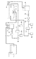
図1にプールあるいは浴場施設等で用いられる一般的な水循環システムの構成例を示す。
この循環システムにおいて、1は受水槽,2はプールあるいは浴槽等の循環水利用設備,3は循環水排水口,4はオーバーフロー水回収溝,5は循環水回収槽,6はオーバーフロー水回収槽,7は循環水ヘアーキャッチャー,8はオーバーフロー水ヘアーキャッチャー,9は循環水ポンプ,10はオーバーフロー水ポンプ,11は循環水濾過装置,12はオーバーフロー水濾過装置である。
この他に凝集剤注入装置13及び14,塩素自動注入装置15及び16,バルブ17及び18が使用される。
【0004】
循環水利用設備2の循環水排水口3から排出された循環水は循環水回収槽5に流入し、循環水ヘアーキャッチャー7、循環水濾過装置11を経て循環水利用設備2に循環流入する。その途中、凝集剤注入装置13により汚れ凝集用凝集剤が注入され、凝集した汚れが循環水濾過装置11で除去され、塩素自動注入装置15により滅菌用塩素が注入される。
なお、この循環は循環水ポンプ9とバルブ17によって行われる。
【0005】
循環水利用設備2からのオーバーフロー水はオーバーフロー水回収溝4からオーバーフロー水回収槽6に流入し、オーバーフロー水ヘアーキャッチャー8、オーバーフロー水濾過装置12を経てオーバーフロー水利用設備2に流入する。その途中、凝集剤注入装置14により汚れ凝集用凝集剤が注入され、凝集した汚れが循環水濾過装置12で除去され、塩素自動注入装置16により滅菌用塩素が注入される。
なお、この循環はオーバーフロー水ポンプ9とバルブ17によって制御される。
これらの他に、消費され外部に排出される水を補充するための受水槽1が使用され、受水槽1から循環水回収槽5に補充水が供給される。
【0006】
プールや浴場施設等と同様に水を循環させて使用しているシステムに、クーリングタワーを用いた冷却システムがある。
図2に示すのはクーリングタワーによる冷房システムの従来例である。
この循環システムにおいて、41は冷却水タンク,42はクーリングタワー,43は散水箱,44は充填材,45は水槽,46はファン,47は冷却水循環ポンプ,48は熱交換器,49は冷却施設,50は水補給口である。
この他にバルブ51及び52が使用される。
【0007】
クーリングタワー42の散水箱43から充填材44に散布された水は充填材44中を流下する間にファン46によって充填材44の側面から吸入された空気と混合され、蒸発潜熱を失うことにより冷却され、水槽45に落下し、バルブ51を経由して冷却水タンク41に流入する。
流入した冷却水は冷却水循環ポンプ47により熱交換器48に送り込まれ、ビルディング・工場等の冷却施設49で暖められた水から熱を受け取ることによりその水を冷却するとともに自らは暖められ、クーリングタワー42に環流する。
クーリングタワーで空気と混合された際に蒸発等によって失われた水はバルブ52を経由して水補給口50から補給される。
【0008】
これらの水循環システムでは、各装置及び配管に生成される錆、各装置及び配管に水中の無機物が沈着することによるスケールが発生する他、藻の発生、水中の細菌が生成する粘着物質であるスライム及び藻あるいはスライム中に生息する細菌(特に重篤な肺炎を起こすことがあるレジオネラ属菌)の滅菌あるいは除去が大きな課題となっている。
【0009】
プールあるいは浴場施設等水が人体に直接接触する水循環システムにおいては、水浄化のために循環水濾過装置9及びオーバーフロー水濾過装置12の濾過剤として従来、砂,砂利等の鉱物質,植物等の繊維質あるいは多孔性の合成樹脂を利用するとともに、凝集剤注入装置14により汚れ凝集用凝集剤を注入し、塩素自動注入装置16により滅菌用塩素を注入している。
一方、クーリングタワーを用いた冷房システムは水が直接に触れることはないと考えられ、薬剤を用いた処理が採られている。
【0010】
最近マイナス・イオンによるリラックス効果及びリフレッシュ効果が注目されている。このマイナス・イオンは酸素イオンO2 −を複数の水分子(H2O)が取り囲んだもので[O2 −(H2O)n]と表現される。
また、マイナス・イオンと同時に水素イオンH+を複数の水分子(H2O)が取り囲んだプラス・イオンも同量生成され、このプラス・イオンは[H+(H2O)m]と表現される。
これらのマイナス・イオンとプラス・イオンは同量生成され、その混合体はプラズマ・クラスター・イオンとよばれる。
【0011】
マイナス・イオンにはリラックス効果及びリフレッシュ効果だけでなく毛髪に対する好影響の存在が確認されている。
さらに、人体に対する好影響以外に、冷蔵庫中の野菜の変色抑制効果及び水分蒸発量減少効果が確認されている。
また、マイナス・イオンに付随する水分子のクラスターはできるだけ小さいことが望ましいとされている。
【0012】
プラズマ・クラスター・イオンの場合にはインフルエンザ・ウィルスの表面にある蛋白質赤血球凝集素の構造を変えるため、ウィルスの機能が停止し、不活化されることによるインフルエンザ感染予防効果が確認されている。(日経エレクトロニクス2002年10月21日号第63ページ参照)
また、カビ発生の抑制効果も確認されている。
【0013】
これらマイナス・イオン及びプラス・イオンの発生方法としては従来、放電によるもの、水滴同士を衝突させることによるものがあり、最も簡易な方法として放電によるものが多用されているが、放電の際にオゾンが発生することがあり、オゾンの異臭と強い酸化作用への対策が課題となっている。
【0014】
マイナス・イオン及びプラス・イオンの発生方法としてこの他に鉱物を用いるものがあり、鉱物として天然のものとしてトルマリン,電気石,角閃石,麦飯石が用いられ、また人工のものとしてセラミックのボールも用いられている。
【0015】
【発明の概要】
このような状況に鑑みて、本出願ではマイナス・イオン,プラス・イオン及びプラズマ・クラスター・イオンを生成する水浄化材,水浄化装置及び水浄化システムの発明を提供する。
【0016】
本発明に係る水浄化材は比重が小さなプラスチック素材にセラミックス粉を混練した素材を表面積が大きく、空隙率が大きく、かつ相互に絡まることがない形状に成形される。
本発明に係る水浄化材は混練されたセラミック粉がマイナス・イオン,プラス・イオン及びプラズマ・クラスター・イオンを生成するとともに、水分子クラスターを微細化する。
【0017】
本発明に係る水浄化装置に封入された水浄化材を耐食性金属製等の通水性容器にその容積の70%程度封入したものである。容器の形状はその使用場所に応じて適宜構成される。
本発明に係る水浄化装置に容器の容積の70%程度封入された水浄化材が水浄化装置を通過する被浄化水の水流により撹拌され、被浄化水と充分に接触し、水浄化材の機能が十分に発揮される。
【0018】
本発明に係る水浄化システムは上記水浄化装置をその適用される水浄化システム中の適切な位置に配設されて構成される。
本発明に係る水浄化システムでは水浄化装置が適切な位置に配設されるため、最適な水浄化が行われる。
【0019】
【実施例】
以下、本件出願に係る発明の実施例を説明する。
図3に本件出願発明に係る水浄化材20の形状の例を示すが、この水浄化材は比重が1より小さいポリエチレンあるいはエチレン・α−オレフィンコポリマーに仮焼成セラミックス粉を10%±5%混入したものであり、比重が1.01±2%程度である。この比重はセラミックス粉の混入率によって1.4前後に必要な値に適宜調整することが可能である。
【0020】
この水浄化材20は次のような方法によって得ることができる。
▲1▼セラミックス混練プラスチックスを円柱状に成形する。
▲2▼セラミックス混練プラスチックス円柱をその半径に沿って薄く螺旋状に切削し、螺旋体を得る。
▲3▼得られた螺旋体を円柱の中心軸に沿って鞍型に成形する。
▲4▼鞍型に形成された螺旋体を螺旋1回転毎にその巻回方向あるいは逆方向に捻る。
【0021】
この形状の水浄化材20は、大きな表面積を有しているため被浄化水との接触面積が充分に大きいため被浄化水と水浄化材20が良好な接触を行うことができる、また大きな空隙率を有しているため、被浄化水が水浄化材20の表面と充分に接触する。また、水浄化材20の端部が表面に露出していないため、水浄化材20同士が絡まり合うことがない。
その結果、常に被浄化水と水浄化材20が良好な接触を行うことによりマイナス・イオン,プラス・イオン及びプラズマ・クラスター・イオンが生成され、大きくなりがちな水分子クラスターの細分化も行われる。
【0022】
螺旋体を切削するのに使用される円柱は直径10〜35mm程度のものが用いられるが、その形状は円柱以外の多角柱であっても良い。また、セラミックスを混練した円柱は固く、滑りやすいため端部を把持して回転させて螺旋状に切削することが容易ではないが、形状として多角柱を採用した場合には切削は容易になる。
【0023】
図4に本発明に係る水浄化材収納容器21の例を示す。
図4の水浄化材収納容器21はステンレス・スチール等の耐食性のあるパンチング・メタルで構成された円筒22の両端に円筒22と同様なステンレス・スチール等の耐食性のあるパンチング・メタルで構成された底部23及び蓋部24を有する円柱形状の容器の中に水浄化材20が収容されて構成されている。
使用されるパンチング・メタルの目25は水浄化材20が通過できない大きさであり、水浄化材20は水浄化材収納容器21の容積の70%程度収容されている。
【0024】
図5に図4に示した円筒形状の水浄化材収納容器21を格納して構成された水浄化装置の例を示す。
この図に示した水浄化装置26は円筒形状の本体27の側面下部に非浄化水流入口28が、側面上部に浄化水流出口29が設けられている。この水浄化装置26はこの実施例では循環水濾過装置11及びオーバーフロー水濾過装置12である。
【0025】
この流入口28及び流出口29の配置関係はこの逆の位置でも可能であり、また、側面ではなく上下の底部30及び蓋部31に配設することも可能であり、その位置は使用状況により適宜選択される。
【0026】
水浄化装置26に格納された水浄化材収納容器21に収容されている水浄化材20の比重は1.10±2%程度と水よりも大きいため、静止した水中では水浄化材収納容器21の下部に滞留している。
このような状態にある水浄化装置26の非浄化水流入口28から非浄化水が流入し、浄化水流出口29から浄化水が流出する。流入した被浄化水は水浄化装置26の内部で下から上に向かって流れるが、この水とともに水浄化材20が水浄化材収納容器21の上部に向かって押し流され、結果として水浄化材20が水浄化材収納容器21の内部で撹拌される。
【0027】
前に述べたように水浄化材20は、被浄化水との接触面積が充分に大きくまた被浄化水中で撹拌されるため被浄化水との接触が良好に行われ、マイナス・イオン,プラス・イオン及びプラズマ・クラスター・イオンが生成され、これらのイオンにより水分子クラスターの細分化が行われる。これによる界面活性効果が活発化し、細菌発生の原因となるスライムや藻類の剥離が行われ、良好な浄化水が得られるとともに、錆の発生及びスケールの付着も抑制される。また、その際に被浄化水中の汚濁物質が水浄化材20に吸着されて除去される。
【0028】
得られた浄化水に各々塩素自動注入装置15及び16で残留塩素濃度を規定した規制に適合するように塩素が注入され、最終的にプールあるいは浴槽等の循環水利用設備に環流する。
【0029】
水浄化材20の形成方法にはこの他に特開平7−75712に開示されている方法がある。
【0030】
本発明に係る水浄化材収納容器21の外形は図4に示した円筒形状の他に図6(a)に示した直方体形状,(b)に示した円錐形状,(c)に示した角錐形状,(d)に示した截頭円錐形状あるいは(e)に示した截頭角錐形状等水浄化材収納容器21を格納する水浄化装置の形状に応じて適宜選択することができる。
【0031】
これ以外に水浄化材収納容器21は循環水経路中に独立した水浄化装置として循環水回収槽5,オーバーフロー水回収槽6,循環水濾過装置11,オーバーフロー水濾過装置12とは別体に設けることも可能である。
さらに、水浄化材収納容器21は水浄化装置26に格納せずに循環水利用設備2の壁面,循環水排水口3あるいはオーバーフロー水回収溝4に配置することも可能である。
【0032】
図2に示されたクーリングタワーを用いた冷却システムの場合には、本発明に係る水浄化装置は散水箱43,水槽45冷却水タンク41に設置される。また、必要ならば冷却施設49を循環する水の経路にも設置される。
【0033】
また、給湯システム中あるいは温水暖房システム中に温湯を貯蔵する装置が設けられている場合には、その温湯貯蔵装置中に本発明に係る水浄化装置を設置する。
【図面の簡単な説明】
【図1】従来の循環水利用システムの構成図。
【図2】クーリングタワーによる従来の冷却システムの構成図。
【図3】本件出願発明に係る水浄化材の形状例説明図。
【図4】本発明に係る水浄化材収納容器の例説明図。
【図5】本発明に係る水浄化材収納容器の他の例説明図。
【図6】本発明に係る水浄化装置の例説明図。
【符号の説明】
1 受水槽
2 循環水利用設備
3 循環水排水口
4 オーバーフロー水回収溝
5 循環水回収槽
6 オーバーフロー水回収槽
7 循環水ヘアーキャッチャー
8 オーバーフロー水ヘアーキャッチャー
9 循環水ポンプ
10 オーバーフロー水ポンプ
11 循環水濾過装置
12 オーバーフロー水濾過装置
13,14 凝集剤注入装置
15,16 塩素自動注入装置
17,18,51,52 バルブ
20 水浄化材
21 水浄化材収納容器
22 パンチング・メタル円筒
23 パンチング・メタル底部
24 パンチング・メタル蓋部
25 目
26 水浄化装置
27 水浄化装置本体
28 非浄化水流入口
29 浄化水流出口
30 水浄化装置底部
31 水浄化装置蓋部
41 冷却水タンク
42 クーリングタワー
43 散水箱
44 充填材
45 水槽
46 ファン
47 冷却水循環ポンプ
48 熱交換器
49 冷却施設
50 水補給口[0001]
[Industrial applications]
The present invention relates to a water purification material for purifying water used in circulation, a water purification material mixed with the water purification material, a water purification device containing the water purification material, and a water circulation utilization system.
[0002]
[Prior art]
In systems such as pools and bathtubs that circulate or use water or hot water, filtration devices and sterilization devices are used, and these devices are required to be installed in facilities used by an unspecified number of people.
Also, in a cooling tower that cools circulating cooling water with a large air conditioner, the water comes into direct contact with air, thus contaminating the water.
In addition, when distributing hot water to a plurality of use locations, the heated hot water is stored in the hot water storage tank. In such a situation, it may be difficult to keep the hot water in the hot water storage tank clean.
[0003]
FIG. 1 shows a configuration example of a general water circulation system used in a pool or a bath facility.
In this circulation system, 1 is a water receiving tank, 2 is circulating water utilization equipment such as a pool or a bathtub, 3 is a circulating water drainage port, 4 is an overflow water recovery groove, 5 is a circulating water recovery tank, 6 is an overflow water recovery tank, 7 is a circulating water hair catcher, 8 is an overflow water hair catcher, 9 is a circulating water pump, 10 is an overflow water pump, 11 is a circulating water filtration device, and 12 is an overflow water filtration device.
In addition,
[0004]
The circulating water discharged from the circulating water discharge port 3 of the circulating
This circulation is performed by the circulating
[0005]
The overflow water from the circulating
This circulation is controlled by the
In addition to these, a water receiving tank 1 for replenishing water consumed and discharged to the outside is used, and replenishing water is supplied from the water receiving tank 1 to the circulating
[0006]
A cooling system using a cooling tower is a system that circulates and uses water in the same manner as a pool or a bath facility.
FIG. 2 shows a conventional example of a cooling system using a cooling tower.
In this circulation system, 41 is a cooling water tank, 42 is a cooling tower, 43 is a watering box, 44 is a filler, 45 is a water tank, 46 is a fan, 47 is a cooling water circulation pump, 48 is a heat exchanger, 49 is a cooling facility, 50 is a water supply port.
In addition,
[0007]
The water sprayed from the
The inflowing cooling water is sent to a heat exchanger 48 by a cooling
Water lost due to evaporation or the like when mixed with air in the cooling tower is supplied through a
[0008]
In these water circulation systems, rust generated in each device and piping, scale due to the deposition of inorganic substances in water on each device and piping is generated, algae is generated, slime which is an adhesive substance generated by bacteria in the water. In addition, sterilization or removal of bacteria inhabiting in algae or slime (particularly Legionella spp., Which may cause severe pneumonia) has become a major issue.
[0009]
In a water circulation system in which water directly contacts a human body, such as a pool or a bath facility, the water is conventionally used as a filtering agent for a circulating
On the other hand, it is considered that a cooling system using a cooling tower does not come into direct contact with water, and treatment using a chemical is employed.
[0010]
Recently, attention has been paid to a relaxing effect and a refreshing effect by negative ions. This negative ion is an oxygen ion O 2 − surrounded by a plurality of water molecules (H 2 O), and is expressed as [O 2 − (H 2 O) n ].
At the same time as the negative ion, a positive ion in which the hydrogen ion H + is surrounded by a plurality of water molecules (H 2 O) is generated in the same amount, and this positive ion is expressed as [H + (H 2 O) m ]. Is done.
An equal amount of these negative and positive ions are produced, and the mixture is called plasma cluster ions.
[0011]
It has been confirmed that negative ions have not only a relaxing effect and a refreshing effect but also a favorable effect on hair.
Furthermore, in addition to the favorable effect on the human body, it has been confirmed that the discoloration of vegetables in the refrigerator is suppressed and the amount of water evaporated is reduced.
It is also considered desirable that the cluster of water molecules accompanying the negative ion be as small as possible.
[0012]
In the case of plasma cluster ions, since the structure of protein hemagglutinin on the surface of the influenza virus is changed, the virus stops functioning and is inactivated, thereby confirming the effect of preventing influenza infection. (See page 63 of the Nikkei Electronics October 21, 2002 issue)
In addition, the effect of suppressing the occurrence of mold has been confirmed.
[0013]
Conventionally, there are methods of generating these negative ions and positive ions by discharge and by collision of water droplets.The simplest method is to use discharge. Occasionally, the countermeasures against the off-flavor and strong oxidizing action of ozone are issues.
[0014]
Mineral and positive ions can also be generated by using minerals, such as tourmaline, tourmaline, amphibolite, and barite, which are natural, and ceramic balls are also used as artificial ones. Used.
[0015]
Summary of the Invention
In view of such circumstances, the present application provides an invention of a water purification material, a water purification device, and a water purification system that generate negative ions, positive ions, and plasma cluster ions.
[0016]
The water purifying material according to the present invention is formed by kneading a ceramic material with a plastic material having a small specific gravity into a shape having a large surface area, a large porosity, and no entanglement with each other.
In the water purifying material according to the present invention, the kneaded ceramic powder generates negative ions, positive ions, and plasma cluster ions, and makes water molecule clusters fine.
[0017]
The water purifying material sealed in the water purifying apparatus according to the present invention is sealed in a water-permeable container made of a corrosion-resistant metal or the like at about 70% of its volume. The shape of the container is appropriately configured according to the place of use.
The water purification material enclosed in the water purification device according to the present invention by about 70% of the volume of the container is agitated by the flow of the water to be purified passing through the water purification device, makes sufficient contact with the water to be purified, and Functions are fully demonstrated.
[0018]
The water purification system according to the present invention is configured by disposing the water purification device at an appropriate position in the water purification system to which the water purification device is applied.
In the water purification system according to the present invention, since the water purification device is disposed at an appropriate position, optimal water purification is performed.
[0019]
【Example】
Hereinafter, embodiments of the invention according to the present application will be described.
FIG. 3 shows an example of the shape of the water purifying material 20 according to the present invention. In this water purifying material, 10% ± 5% of calcined ceramic powder is mixed into polyethylene or ethylene / α-olefin copolymer having a specific gravity smaller than 1. The specific gravity is about 1.01 ± 2%. The specific gravity can be appropriately adjusted to a necessary value around 1.4 depending on the mixing ratio of the ceramic powder.
[0020]
This water purifying material 20 can be obtained by the following method.
(1) The ceramics-kneaded plastics are formed into a cylindrical shape.
{Circle around (2)} A ceramic kneaded plastic cylinder is thinly and spirally cut along its radius to obtain a spiral body.
{Circle around (3)} The obtained spiral is formed into a saddle shape along the central axis of the cylinder.
{Circle around (4)} The spiral body formed in a saddle shape is twisted in the winding direction or in the opposite direction for each rotation of the spiral.
[0021]
The water purifying material 20 of this shape has a large surface area and therefore has a sufficiently large contact area with the water to be purified, so that the water to be purified and the water purifying material 20 can make good contact with each other. The water to be purified comes into sufficient contact with the surface of the water purification material 20 because it has a rate. Further, since the end of the water purification material 20 is not exposed on the surface, the water purification materials 20 do not become entangled with each other.
As a result, since the water to be purified and the water purification material 20 always make good contact, negative ions, positive ions, and plasma cluster ions are generated, and the water molecule cluster, which tends to become large, is also subdivided. .
[0022]
The cylinder used for cutting the helical body has a diameter of about 10 to 35 mm, but the shape may be a polygonal pillar other than the cylinder. Further, the cylinder kneaded with ceramics is hard and slippery, so that it is not easy to grip and rotate the end to rotate it into a spiral shape. However, when a polygonal column is employed as the shape, the cutting becomes easy.
[0023]
FIG. 4 shows an example of the water purification material storage container 21 according to the present invention.
The water purifying material storage container 21 shown in FIG. 4 is made of a corrosion-resistant punching metal such as stainless steel at both ends of a
The
[0024]
FIG. 5 shows an example of a water purification device configured to house the cylindrical water purification material storage container 21 shown in FIG.
The water purification device 26 shown in this figure is provided with a
[0025]
The arrangement relationship between the
[0026]
The specific gravity of the water purification material 20 stored in the water purification material storage container 21 stored in the water purification device 26 is about 1.10 ± 2%, which is larger than water. Stagnated at the bottom.
Non-purified water flows in from the
[0027]
As described above, the water purification material 20 has a sufficiently large contact area with the water to be purified and is well stirred with the water to be purified because it is stirred in the water to be purified. Ions and plasma cluster ions are generated, and these ions cause fragmentation of the water molecule cluster. As a result, the surface active effect is activated, slime and algae causing bacteria are removed, and good purified water is obtained. At the same time, generation of rust and adhesion of scale are suppressed. At that time, pollutants in the water to be purified are adsorbed by the water purification material 20 and removed.
[0028]
Chlorine is injected into the obtained purified water by the
[0029]
As another method for forming the water purification material 20, there is a method disclosed in Japanese Patent Application Laid-Open No. 7-75712.
[0030]
The outer shape of the water purifying material storage container 21 according to the present invention is, in addition to the cylindrical shape shown in FIG. 4, a rectangular parallelepiped shape shown in FIG. 6A, a conical shape shown in FIG. 6B, and a pyramid shown in FIG. The shape can be appropriately selected according to the shape of the water purification device that stores the water purification material storage container 21, such as the shape of a truncated cone shown in (d) or the shape of a truncated pyramid shown in (e).
[0031]
In addition, the water purifying material storage container 21 is provided separately from the circulating
Further, the water purifying material storage container 21 can be disposed in the wall surface of the circulating
[0032]
In the case of the cooling system using the cooling tower shown in FIG. 2, the water purification device according to the present invention is installed in the watering
[0033]
When a device for storing hot water is provided in the hot water supply system or the hot water heating system, the water purification device according to the present invention is installed in the hot water storage device.
[Brief description of the drawings]
FIG. 1 is a configuration diagram of a conventional circulating water utilization system.
FIG. 2 is a configuration diagram of a conventional cooling system using a cooling tower.
FIG. 3 is a diagram illustrating an example of the shape of a water purification material according to the present invention.
FIG. 4 is an explanatory view of an example of a water purification material storage container according to the present invention.
FIG. 5 is an explanatory view of another example of the water purification material storage container according to the present invention.
FIG. 6 is an explanatory view of an example of a water purification device according to the present invention.
[Explanation of symbols]
DESCRIPTION OF SYMBOLS 1
Claims (18)
73±4%のSiO2,15±4%のAl2O3,3±4%のLi2O,3±0.5%のCoO3及び残余がMgO,K2O,CaOである組成のセラミックスの粉砕物をエチレン・α−オレフィンコポリマーに混入し、混入比率をセラミックスの粉砕物が10±5%、エチレン・α−オレフィンコポリマーが90±5%とした水浄化材を濾過装置に使用する、水循環利用システム。73 ± 4% of SiO 2 , 15 ± 4% of Al 2 O 3 , 3 ± 4% of Li 2 O, 3 ± 0.5% of CoO 3 and the balance of MgO, A pulverized ceramic material having a composition of K 2 O and CaO was mixed into an ethylene / α-olefin copolymer, and the mixing ratio was 10 ± 5% for the pulverized ceramic material and 90 ± 5% for the ethylene / α-olefin copolymer. A water circulation utilization system that uses a water purification material for a filtration device.
Priority Applications (3)
| Application Number | Priority Date | Filing Date | Title |
|---|---|---|---|
| JP2003093365A JP2004298708A (en) | 2003-03-31 | 2003-03-31 | Water cleaning material, water cleaning agent, water cleaning apparatus, and system for circularly utilizing water |
| PCT/JP2004/004537 WO2004087581A1 (en) | 2003-03-31 | 2004-03-30 | Water clarification material, water clarification member, water clarification apparatus and system for circulation and utilization of water |
| KR1020057017722A KR20050114672A (en) | 2003-03-31 | 2004-03-30 | Water clarification material, water clarification member, water clarification apparatus and system for circulation and utilization of water |
Applications Claiming Priority (1)
| Application Number | Priority Date | Filing Date | Title |
|---|---|---|---|
| JP2003093365A JP2004298708A (en) | 2003-03-31 | 2003-03-31 | Water cleaning material, water cleaning agent, water cleaning apparatus, and system for circularly utilizing water |
Publications (2)
| Publication Number | Publication Date |
|---|---|
| JP2004298708A true JP2004298708A (en) | 2004-10-28 |
| JP2004298708A5 JP2004298708A5 (en) | 2006-06-29 |
Family
ID=33127357
Family Applications (1)
| Application Number | Title | Priority Date | Filing Date |
|---|---|---|---|
| JP2003093365A Pending JP2004298708A (en) | 2003-03-31 | 2003-03-31 | Water cleaning material, water cleaning agent, water cleaning apparatus, and system for circularly utilizing water |
Country Status (3)
| Country | Link |
|---|---|
| JP (1) | JP2004298708A (en) |
| KR (1) | KR20050114672A (en) |
| WO (1) | WO2004087581A1 (en) |
Cited By (1)
| Publication number | Priority date | Publication date | Assignee | Title |
|---|---|---|---|---|
| WO2018021253A1 (en) * | 2016-07-28 | 2018-02-01 | トヨタ紡織株式会社 | Tourmaline treatment device and cooling water circulation system including same |
Families Citing this family (1)
| Publication number | Priority date | Publication date | Assignee | Title |
|---|---|---|---|---|
| JP5174422B2 (en) * | 2007-10-21 | 2013-04-03 | エム・ケー開発株式会社 | Antifouling method and antifouling device for circulating water and facilities using the circulating water |
Family Cites Families (3)
| Publication number | Priority date | Publication date | Assignee | Title |
|---|---|---|---|---|
| JPS62202400U (en) * | 1986-06-13 | 1987-12-23 | ||
| JP3705500B2 (en) * | 1993-07-26 | 2005-10-12 | 日本治水株式会社 | Production method of active water |
| JPH11197675A (en) * | 1998-01-19 | 1999-07-27 | Seisui:Kk | Functional ceramics water catalytic treatment apparatus, functional ceramics, water treatment system utilizing the same and catalytic water use method |
-
2003
- 2003-03-31 JP JP2003093365A patent/JP2004298708A/en active Pending
-
2004
- 2004-03-30 KR KR1020057017722A patent/KR20050114672A/en not_active Application Discontinuation
- 2004-03-30 WO PCT/JP2004/004537 patent/WO2004087581A1/en active Search and Examination
Cited By (3)
| Publication number | Priority date | Publication date | Assignee | Title |
|---|---|---|---|---|
| WO2018021253A1 (en) * | 2016-07-28 | 2018-02-01 | トヨタ紡織株式会社 | Tourmaline treatment device and cooling water circulation system including same |
| CN109311708A (en) * | 2016-07-28 | 2019-02-05 | 丰田纺织株式会社 | Tourmaline processing unit and cooling water recirculation system with the tourmaline processing unit |
| US10703655B2 (en) | 2016-07-28 | 2020-07-07 | Toyota Boshoku Kabushiki Kaisha | Tourmaline treatment device and cooling water circulation system including same |
Also Published As
| Publication number | Publication date |
|---|---|
| KR20050114672A (en) | 2005-12-06 |
| WO2004087581A1 (en) | 2004-10-14 |
Similar Documents
| Publication | Publication Date | Title |
|---|---|---|
| US6872303B2 (en) | Water treatment cartridge | |
| US20200398231A1 (en) | Microbubble generator and cooling water circulation system equipped with same | |
| KR101356752B1 (en) | Air Cleaner | |
| KR101511335B1 (en) | Reverse osmosis filter having alkali support cartridge | |
| JP2004298708A (en) | Water cleaning material, water cleaning agent, water cleaning apparatus, and system for circularly utilizing water | |
| JP2004298708A5 (en) | ||
| JP3425411B2 (en) | Cooling water purification equipment for cooling tower | |
| KR100613853B1 (en) | device for filtering supplied water | |
| JP2003164714A (en) | Filter | |
| WO2005003042A1 (en) | Mineral water feeding apparatus | |
| JP3577948B2 (en) | Magnetically treated water generator | |
| KR20190059725A (en) | Water purifier for domestic nano bubble generation | |
| KR102349264B1 (en) | Complex purifier with hot and cold water function and with improved sterlization and negative ion generating function | |
| WO2004033379A1 (en) | System for producing magnetization improved water to create a negative ion oxygen | |
| KR20200124890A (en) | Screw type wet contact air cleaner | |
| JP2002361231A (en) | Device for manufacturing purified water | |
| JP3140099U (en) | Filtration device | |
| KR101689009B1 (en) | System for purifying exhausted gas | |
| JP3094405U (en) | Screen water purifier or water conditioner | |
| KR102218048B1 (en) | Water to stabilize the water treatment device having means for reaction) | |
| JP3194144U (en) | Water purification cartridge and water purification device | |
| RU2787823C1 (en) | Gas injection system for optimising the generation of nano bubbles in disinfectant solution | |
| CN201062216Y (en) | Ozone sterilization purifier | |
| KR200415503Y1 (en) | Soft water device | |
| JP2004074133A (en) | Fully automatic cleaned-and-activated water production device |
Legal Events
| Date | Code | Title | Description |
|---|---|---|---|
| A711 | Notification of change in applicant |
Free format text: JAPANESE INTERMEDIATE CODE: A711 Effective date: 20050527 |
|
| A521 | Written amendment |
Free format text: JAPANESE INTERMEDIATE CODE: A821 Effective date: 20050527 |
|
| A711 | Notification of change in applicant |
Free format text: JAPANESE INTERMEDIATE CODE: A711 Effective date: 20050713 |
|
| A521 | Written amendment |
Free format text: JAPANESE INTERMEDIATE CODE: A821 Effective date: 20050713 |
|
| A521 | Written amendment |
Free format text: JAPANESE INTERMEDIATE CODE: A523 Effective date: 20051102 |
|
| A521 | Written amendment |
Free format text: JAPANESE INTERMEDIATE CODE: A523 Effective date: 20060330 |
|
| A621 | Written request for application examination |
Free format text: JAPANESE INTERMEDIATE CODE: A621 Effective date: 20060330 |
|
| A521 | Written amendment |
Free format text: JAPANESE INTERMEDIATE CODE: A523 Effective date: 20060426 |
|
| A131 | Notification of reasons for refusal |
Free format text: JAPANESE INTERMEDIATE CODE: A131 Effective date: 20090421 |
|
| A02 | Decision of refusal |
Free format text: JAPANESE INTERMEDIATE CODE: A02 Effective date: 20090818 |