JP2004289873A - Image processing apparatus - Google Patents
Image processing apparatus Download PDFInfo
- Publication number
- JP2004289873A JP2004289873A JP2004168454A JP2004168454A JP2004289873A JP 2004289873 A JP2004289873 A JP 2004289873A JP 2004168454 A JP2004168454 A JP 2004168454A JP 2004168454 A JP2004168454 A JP 2004168454A JP 2004289873 A JP2004289873 A JP 2004289873A
- Authority
- JP
- Japan
- Prior art keywords
- density
- tracking pattern
- signal
- tracking
- toner patch
- Prior art date
- Legal status (The legal status is an assumption and is not a legal conclusion. Google has not performed a legal analysis and makes no representation as to the accuracy of the status listed.)
- Pending
Links
Images


Abstract
Description
この発明は、入力した画像信号に基づいて画像処理を行なって画像形成を行なうとともに、複写物に追跡用(識別用)パターンを形成して、複写に用いた装置を特定し、有価証券等の不法複写を防止する画像処理装置に関する。 According to the present invention, an image is formed by performing image processing based on an input image signal, and a tracking (identification) pattern is formed on a copy to specify an apparatus used for copying, and to output a security document or the like. The present invention relates to an image processing apparatus for preventing illegal copying.
近年では、複写機のカラー複写化に伴い、本来複写されるべきではない有価証券が、オリジナルとほとんど識別がつかないような高画質で複写できるようになり、これがためにカラー複写機が悪用されてしまうおそれが生じてきた。このため、複写禁止原稿の不法複写を防止あるいは抑止するための種々の技術が考えられている。例えば、特開平4−294682号公報に記載されている技術は、複写物上に、肉眼では識別困難ではあるがスキャナ等を用いれば読み取り可能な(潜在性のある)追跡用パターンであって、複写装置を特定する何らかの情報を示す(識別性のある)追跡用パターンを形成する技術である。この技術によれば、複写禁止原稿が複写された場合であっても、複写に用いた装置を特定する手がかりを得ることができる。 In recent years, with the color copying of copiers, securities that should not be copied can be copied with high image quality that can hardly be distinguished from the original, which is why color copiers are abused. The risk has arisen. For this reason, various techniques for preventing or suppressing illegal copying of a copy-inhibited document have been considered. For example, the technology described in Japanese Patent Application Laid-Open No. 4-294682 is a tracking pattern on a copy, which is difficult to identify with the naked eye but can be read (potentially) using a scanner or the like. This is a technique for forming a (identifiable) tracking pattern indicating some information for specifying a copying apparatus. According to this technique, even when a copy-inhibited document is copied, it is possible to obtain a clue for specifying an apparatus used for copying.
一方、カラー複写機などの画像処理装置では、良好なカラーバランスを確保すべく、各原色の濃度特性を維持する必要があり、このために種々の技術が知られている。例えば、特許文献1および特許文献2に記載されている技術は、感光体上または転写体上にトナーパッチ(理想的状態では、所定の目標値濃度を有する原色のトナー像)を各原色毎に形成し、これらのトナーパッチの各濃度を濃度センサによって測定して、測定濃度と目標値との偏差を求め、その偏差がなくなる方向に、画像データをガンマ補正等の濃度補正して、目標とする濃度の画像を得ようとする技術である。この技術によれば、複写に用いられるトナーの製造バラツキや、複写機における光学特性の経時変化などの影響を受けずに、良好なカラーバランスを保つことができる。
On the other hand, in an image processing apparatus such as a color copying machine, it is necessary to maintain the density characteristics of each primary color in order to secure a good color balance, and various techniques are known for this purpose. For example, the techniques described in Patent Literature 1 and
また、上記追跡用パターンを複写物上に形成する技術と、トナーパッチを用いて濃度特性を制御する技術とを組合せたものも存在する。すなわち、画像データに、追跡用パターンを形成するためのデータ信号を付加(合成)し、この合成データ信号に対し、トナーパッチの各濃度に応じてガンマ補正を施す技術も知られている。
しかしながら、かかる組み合わせた技術にあっては、トナーパッチに従った濃度補正によって、確かに所望の濃度を有する画像を得ることができるものの、かかる濃度補正の結果、追跡用パターンの補正が過度に行なわれる場合もあり得る。この場合、追跡用パターンは、巨視的に見れば所望の濃度を有することにはなるが、微視的に見れば、追跡用パターンを構成するドットが過小となって、スキャナ等の読取装置をもってしても、もはや読み込むことができない、あるいは逆に、追跡用パターンを構成するドットが過大となって、追跡用パターンが、肉眼で識別可能となってしまう。いずれにしても、このような場合において追跡用パターンは、識別性と潜在性という2つ性格の一方を失う結果、追跡用パターンとしての働きを果たさなくなってしまうという問題があった。 However, in such a combined technique, although an image having a desired density can be certainly obtained by the density correction according to the toner patch, as a result of the density correction, the tracking pattern is excessively corrected. It may be possible. In this case, the tracking pattern has a desired density when viewed macroscopically, but when viewed microscopically, the dots constituting the tracking pattern become too small, and a reading device such as a scanner is used. Even so, it is no longer possible to read, or conversely, the dots forming the tracking pattern become too large and the tracking pattern becomes identifiable with the naked eye. In any case, in such a case, there is a problem in that the tracking pattern loses one of the two characteristics of discrimination and latentness, and as a result, does not function as the tracking pattern.
この発明は、上述した問題に鑑みてなされたもので、その目的とするところは、形成すべき記録画像の濃度が変動しても、追跡用パターンを、肉眼では識別が困難であるが、スキャナ等では識別できるようにした画像処理装置を提供することにある。 SUMMARY OF THE INVENTION The present invention has been made in view of the above-described problems, and an object of the present invention is to make it difficult to identify a tracking pattern with the naked eye even when the density of a print image to be formed fluctuates. It is another object of the present invention to provide an image processing apparatus which can be identified.
上述した課題を解決するために、本発明は、追跡用記録パターンを形成するための追跡用パターン信号を発生する発生手段と、所定のトナー濃度に対応するトナーパッチ信号に基づいてトナーパッチを形成するトナーパッチ形成手段と、前記トナーパッチ形成手段によって形成されたトナーパッチの濃度を測定するトナー濃度センサと、前記トナー濃度センサにより測定されたトナーパッチの濃度と、予め決められたトナーパッチの濃度の目標値との差を認識する認識手段と、前記認識手段により認識された濃度差に基づいて前記追跡用記録パターンの形状が前記濃度値の差に対応する形状となるように、前記トナーパッチ信号とは独立に前記追跡用パターン信号の補正を行う補正手段と、前記補正手段により補正された追跡パターン信号および前記トナーパッチ信号とに基づいて記録画像を形成する形成手段とを具備することを特徴とする画像処理装置を提供する。 In order to solve the above-described problem, the present invention provides a generation unit that generates a tracking pattern signal for forming a tracking recording pattern, and forms a toner patch based on a toner patch signal corresponding to a predetermined toner density. Toner patch forming means, a toner density sensor for measuring the density of the toner patch formed by the toner patch forming means, a toner patch density measured by the toner density sensor, and a predetermined toner patch density Recognition means for recognizing a difference from the target value, and the toner patch so that the shape of the tracking recording pattern has a shape corresponding to the density value difference based on the density difference recognized by the recognition means. Correction means for correcting the tracking pattern signal independently of the signal; and a tracking pattern signal and a correction signal corrected by the correction means. To provide an image processing apparatus characterized by comprising a forming means for forming a recorded image on the basis of the fine the toner patch signal.
前記補正手段は、前記追跡用記録パターンを構成するドットの数が変更されるように前記追跡用パターン信号を補正するようにしてもよい。 The correction means may correct the tracking pattern signal so that the number of dots forming the tracking recording pattern is changed.
また、前記補正手段は、前記追跡用記録パターンの大きさが変更されるように前記追跡用パターン信号を補正するようにしてもよい。 Further, the correction means may correct the tracking pattern signal so that the size of the tracking recording pattern is changed.
また、前記補正手段は、前記追跡用記録パターンを構成するドットの面積が変更されるように前記追跡用パターン信号を補正するようにしてもよい。 Further, the correction means may correct the tracking pattern signal so that the area of the dots constituting the tracking recording pattern is changed.
前記補正手段は、前記濃度差として濃度偏差平均値を用いるようにしてもよい。 The correction means may use a density deviation average value as the density difference.
1:実施例の構成
以下、この発明の一実施例について図面を参照して説明する。
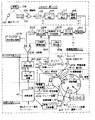
図1は、この実施例の画像処理装置を組み込んだフルカラー複写機の構成を示すブロック図である。この図に示すように、このフルカラー複写機は、スキャナー部100と、画像処理部200と、ROS光学系300と、画像形成部400とから構成されている。まず、スキャナー部100においては、露光ランプ102が原稿109を照射し、その反射光をCCD103が読み込み、その出力を増幅器104が適切なレベルまで増幅する。そして、増幅器104の出力は、A/Dコンバータ105によりディジタル画像データに変換され、シェーディング補正部106によりシェーディング補正され、ギャップ補正部107によりギャップ補正された後、濃度変換器108により反射データから濃度データに変換されて、画像処理部200に供給される。すなわち、スキャナー部100においては、原稿109が読み取られて、その内容が濃度データL*、a*、b*として出力される。
1: Configuration of Embodiment Hereinafter, an embodiment of the present invention will be described with reference to the drawings.
FIG. 1 is a block diagram showing the configuration of a full-color copying machine incorporating the image processing apparatus of this embodiment. As shown in this figure, this full-color copying machine includes a scanner unit 100, an image processing unit 200, a ROS optical system 300, and an image forming unit 400. First, in the scanner unit 100, the exposure lamp 102 irradiates the document 109, the
次に、画像処理部200の内部において201は色変換部であり、上記濃度データL*、a*、b*を、原色YMCKの濃度によって表現される画像データに変換する。そして、この画像データは、1ページ毎にY、M、C、Kの順に出力される。202はガンマ補正回路であり、画像形成部400の階調性に合わせて各色階調の補正が行なわれる。203は追跡用パターン付加回路であり、色階調が補正された画像データに、追跡用パターンを付加する。204もガンマ補正回路であり、追跡用パターンが付加された画像データに、ガンマ補正を施して出力する。なお、追跡用パターン付加回路203およびガンマ補正回路204は、演算装置411の制御の下、後述するトナーパッチの測定濃度によってそれぞれ独立して制御されて、追跡用パターン付加回路203にあっては、追跡用パターンを構成するドットの大きさや面積が制御され、また、ガンマ補正回路204にあっては、ガンマ補正の際に用いるルックアップテーブルの選択が制御される。なお、その詳細については詳細する。
Next, inside the image processing unit 200,
205はD/Aコンバータであり、ガンマ補正された画像データをアナログ信号に変換し出力する。206は三角波発生器であり、所定周期の三角波を出力する。207は三角波調整回路であり、この三角波のレベル等を適宜調整して出力する。208は比較器であり、D/Aコンバータ205から出力されたアナログ信号のレベルと、三角波調整回路207から出力された三角波のレベルとを比較し、アナログ信号が三角波のレベル以上である場合は“0”信号を、それ以外の場合には“1”信号を出力する。したがって、比較器208の出力信号は、適宜“1”または“0”になるパルス信号になる。かかるパルス信号のデューティ比はアナログ信号のレベルが高いほど、すなわち濃度が高いほど小となる。
A D / A
次に、209はトナーパッチ信号発生回路であり、トナーパッチの現像位置に対応するタイミングにおいて、所定のトナー濃度に対応するレベルのアナログ信号(トナーパッチ信号)を比較器208に供給する。このアナログ信号は、D/Aコンバータ205から出力されるアナログ信号と同様に、三角波調整回路207からの三角波と比較され、その結果に応じたパルス信号が比較器208から出力される。
Next,
また、ROS光学系300の内部において301はレーザ駆動回路であり、比較器208から出力されるパルス信号に同期してレーザ302をオン/オフ制御する。すなわち、パルス信号が“1”である場合にはレーザ302を点灯させる一方、“0”である場合には消灯させる。また、レーザ光量は、演算装置400で制御されるレーザ光量可変装置306によって可変となっている。そして、レーザ302から放射されたレーザ光は、ポリゴン303、fθレンズ304および反射ミラー305を順次介して、収束される。
Reference numeral 301 in the ROS optical system 300 denotes a laser driving circuit, which controls on / off of the laser 302 in synchronization with a pulse signal output from the comparator 208. That is, the laser 302 is turned on when the pulse signal is “1”, and is turned off when the pulse signal is “0”. The laser light amount is variable by a laser light amount
一方、画像形成部400の内部において411は演算装置であり、制御プログラムに基づいて他の構成要素を制御する。402は帯電装置であり、演算装置411および帯電量可変装置409の制御の下、感光体401を一様にマイナス帯電させる。感光体401は、図1において時計回りに回転し、帯電装置402によって帯電された後に上記レーザ光が放射される。これにより、感光体401上には潜像が形成される。403はロータリー現像装置であり、感光体401に各原色のトナーを付着させる。412はトナーディスペンス装置であり、演算装置411の制御の下、各色のトナーをロータリー現像装置403に供給する。ここで、トナーディスペンス装置412からロータリー現像装置403に供給されるトナー量は、トナー濃度センサ414の測定結果に基づいて、演算装置411によって制御され、現像バイアスは、演算装置411で制御される現像バイアス可変装置416により変化する。
On the other hand, an
406は転写装置であり、感光体401に付着したトナーを複写用紙上に転写する。404はクリーナー装置であり、感光体401上に残存したトナーを除去する。405は除電ランプであり、感光体401を除電する。410は電位計であり、帯電装置402によって帯電された感光体401の電位を計測する。413は湿度センサであり、感光体401周辺の湿度を計測する。414はトナー濃度センサであり、感光体401上に現像されたトナーの濃度を測定する。そして、電位計410およびセンサ413、414の測定結果は、演算装置411に供給される。
Reference numeral 406 denotes a transfer device that transfers the toner attached to the photoconductor 401 onto copy paper.
1−1:ガンマ補正
ここで、この実施例において行なわれるガンマ補正について説明する。まず、この実施例の画像データにおける各原色YMCKの濃度は、8ビットの256階調(「0」〜「255」)で表現される。しかし、かかる画像データに基づいて単に画像の形成を行なうと、画像形成部400の濃度特性等が変動した際に、忠実度が損なわれる。そこで、ガンマ補正回路202によって、画像データを画像形成部400の濃度特性に合わせて補正し、次に、ガンマ補正回路204によって、追跡用パターンが付加された画像データを、画像形成部400の濃度特性等の変動に合わせて適宜補正することとしている。すなわち、ガンマ補正回路202によるガンマ補正は、画像形成部400の濃度特性に合わせて固定で行なわれるが、ガンマ補正回路204によるガンマ補正は、濃度特性の変動に合わせて可変で行なわれるようになっている。
1-1: Gamma Correction Here, gamma correction performed in this embodiment will be described. First, the density of each primary color YMCK in the image data of this embodiment is represented by 256 gradations of 8 bits (“0” to “255”). However, if an image is simply formed based on such image data, the fidelity is impaired when the density characteristics and the like of the image forming unit 400 fluctuate. Therefore, the image data is corrected by the
このため、ガンマ補正回路204においては、LUT_1〜LUT_7の7種類のルックアップテーブルが設けられる。これらLUT_1〜LUT_7に対応する入出力特性を図2に示す。図示のように、LUT_1〜LUT_3のうちのいずれかが選択された場合には、変換前の画像データの濃度は変換後の画像データのものよりも高くなる。一方、LUT_5〜LUT_7のうちのいずれかが選択された場合には、変換前の画像データの濃度は変換後の画像データのものよりも低くなる。また、LUT_4が選択された場合には、変換前後の画像データの濃度は等しくなる。そして、このうちのいずれか一つが、トナー濃度センサ414により検出されたトナーパッチの濃度値と目標値との偏差にしたがって選択される。詳細には、上記偏差がほとんどなければLUT_4が選択され、また、トナーパッチの濃度値が目標値よりも高く、トナーパッチが濃いならば、その濃さ(偏差)の順番でLUT_7、LUT_6、LUT_5のいずれかが選択され、一方、トナーパッチの濃度値が目標値よりも低く、トナーパッチが薄いならば、その薄さ(偏差)の順番でLUT_1、LUT_2、LUT_3のいずれかが選択されるようになっている。そして、選択されたルックアップテーブルに応じて、ガンマ補正回路204の入出力特性が決定される。
Therefore, the
1−2:追跡用パターン
次に、追跡用パターンについて説明する。
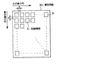
図3は、追跡用パターンが形成される複写用紙30を示す平面図である。この図に示すように、追跡用パターンは、互いに間隔aだけ離れている記録領域31、31……に多数記録されて、複写用紙30のほぼ全面に形成される。これは、コピーの部分的悪用を防止するためであり、切手などのように、複写すべきないものであって、かつ非常に面積が小さいものを複写した場合でも、当該複写物に追跡用パターンが形成されるようにするためである。次に、1つの追跡用パターンが記録される記録領域31について着目すると、追跡用パターンは、図4に示すように、複数の小長方形上を有するドット領域32、32、……から構成される。これらドット領域32、32、……の配置によって、カラー複写機に固有の情報が、予め定められた方式で符号化等されて示される。そして、これを解読することにより、複写に用いたカラー複写機を特定できるようになっている。さらに、1つのドット領域32について着目すると、ドット領域32は、図5に示すように、副走査方向にn行、主走査方向にm列の画素33、33、……から構成されている。
1-2: Tracking Pattern Next, a tracking pattern will be described.
FIG. 3 is a plan view showing the copy sheet 30 on which the tracking pattern is formed. As shown in this figure, a large number of tracking patterns are recorded in
また、一般に(この実施例も含めて)、カラー複写機は、イエロー、マゼンタ、シアンおよび黒の4色の合成でカラー画像が形成されるので、この中で特定色として、例えば、単一色または複数色を組み合わせた色にてドット領域32、32、……を印刷する。かかる特定色としては、肉眼では識別が困難なイエローの単一色が好ましい。
In general (including this embodiment), a color copying machine forms a color image by synthesizing four colors of yellow, magenta, cyan and black. The
1−3:追跡用パターン付加回路
次に、かかる追跡用パターンを、入力画像に付加するための追跡用パターン付加回路203について説明する。
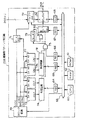
図6は、追跡用パターン付加回路203の構成を示すブロック図である。この図において、51はバッファメモリであり、図1におけるガンマ補正回路202から出力された画像データを記憶する。すなわち、バッファメモリ51には、CCD103により読み取られた原稿109の画像データであって、種々の補正が加えられた画像データが記憶される。52はセレクタであり、バッファメモリ51から読出された画像データを入力端Aを介して受信する一方、所定のカラーデータを入力端Bを介して受信し、選択入力端SELに供給された二値信号に基づいていずれか一方のデータを出力する。すなわち、選択入力端SELに“0”信号が供給されると入力端Aが選択される一方、“1”信号が供給されると入力端Bが選択されて、その選択結果が図1におけるガンマ補正回路204に供給される。60はCPUであり、ROM61に記憶された制御プログラムに基づいて、演算装置411との通信により他の構成要素を制御する。62はRAMであり、バス63を介して、CPU60によって各種のデータを一時的に記憶する。64〜67はレジスタであり、CPU60の制御の下、以下説明するようなデータを記憶し、データを出力する。
1-3: Tracking Pattern Adding Circuit Next, a tracking
FIG. 6 is a block diagram showing the configuration of the tracking
まず、レジスタ64には、複写用紙30上において追跡用パターンを記録すべき記録領域31の座標条件が書込まれる。詳細には、追跡用パターンは、図3に示すように複写用紙30上であって、互いに間隔aを保った記録領域31、31、……に設けられるが、いま、複写用紙30上の任意の画素を想定すると、その座標が一定の条件を満たした場合、この画素は、記録領域31に含まれることになる。すなわち、レジスタ64には、記録領域31、31、……の領域を示す座標条件が書き込まれるのである。
First, the
図6に戻り、レジスタ65には、記録領域31、31、……内の任意の画素がドット領域32、32、……に属する場合の座標条件が書き込まれる。ここで、ドット領域32を構成する画素(図5参照)の主走査方向の数を増減するように、レジスタ65の内容をCPU60の制御により適切に書き換えると、追跡用パターンを構成するドットの面積を変更することができる。
Returning to FIG. 6, a coordinate condition in a case where an arbitrary pixel in the
一方、レジスタ66は、上記追跡パターンを印刷すべきか否かの条件を、“1”または“0”の1ビットのデータとして記憶する。すなわち、追跡用パターンを複写用紙30に印刷すべき場合はレジスタ66に“1”が書込まれる一方、印刷すべきでない場合は“0”が書込まれる。なお、通常の使用状態では、悪用防止のため、レジスタ66には必ず“1”が書込まれる。
On the other hand, the
ところで、図5においては、各ドット領域32、32、……の幅(副走査方向の長さ)は所定値bに設定されている。しかし、この実施例では、一定の条件の下、ドット領域32、32、……の幅が、CPU60の制御により2倍(2b)に設定される。レジスタ67はその条件を1ビットのデータとして記憶するものであり、その内容が“0”である場合はドット領域32、32、……の幅を「b」にすべきことを指定し、“1”である場合は幅を「2b」にすべきことを指定する。これにより、追跡用パターンを構成するドットの数が変化するようになっている。また、レジスタ68は、ドット領域32、32、……に印刷すべき色彩をカラーデータとして記憶するもので、このカラーデータをセレクタ52の入力端Bに供給する。この実施例では、CPU60でレジスタ68にセットされるカラーデータは、通常はイエローである。
By the way, in FIG. 5, the width (length in the sub-scanning direction) of each
次に、70はクロック回路であり、バス63を介したCPU60の制御の下、以下に述べるビデオクロック信号V_CK、ラインシンク信号L_SYNCおよびページシンク信号P_SYNCを出力する。まず、ビデオクロック信号V_CKは、主走査方向に各画素が出力されるタイミングを定めるクロック信号である。また、ラインシンク信号L_SYNCは、副走査方向に各画素が出力されるタイミングを定める信号であり、ビデオクロック信号V_CKの数千倍程度の周期を有する。また、ページシンク信号P_SYNCは、複写用紙30の一ページ分の印刷が終了するタイミングを定める信号であり、ラインシンク信号L_SYNCの数千倍程度の周期を有する。
Next, a
71はカウンタであり、ビデオクロック信号V_CKを計数し、その結果をアドレス信号としてバッファメモリ51に供給する。また、この計数結果は、ページシンク信号P_SYNCによって「0」にリセットされる。72はカウンタであり、ビデオクロック信号V_CKを計数しその結果を出力するとともに、ラインシンク信号L_SYNCによって計数結果が「0」にリセットされる。また、73もカウンタであり、ラインシンク信号L_SYNCを計数しその結果を出力するとともに、ページシンク信号P_SYNCによって計数結果が「0」にリセットされる。したがって、カウンタ72の計数結果は主走査方向における座標に対応し、カウンタ73の計数結果は副走査方向における座標に対応することとなる。
A counter 71 counts the video clock signal V_CK and supplies the result to the
74は判定回路であり、カウンタ72、73の計数結果によって特定された座標が、レジスタ64に記憶された記録領域の座標条件に合致するか否かを判定する。判定回路74は「合致する」と判定すると、AND回路75に“1”信号を出力する。また、76、77はカウンタ、78は判定回路であり、上述したカウンタ72、73および判定回路74と同様に構成されている。判定回路78は、カウンタ76、77の計数結果によって特定された座標が、レジスタ65に記憶されたドット領域の座標条件に合致するか否かを判定する。判定回路77は「合致する」と判定すると、AND回路75に“1”信号を出力する。
A
AND回路75は、判定回路74、78およびレジスタ66からともに“1”信号が出力されると、“1”信号を出力する。79は遅延回路であり、AND回路75の出力信号を所定時間遅延して出力する。この遅延時間は、ラインシンク信号L_SYNCの周期のn倍(nは、図5におけるドット領域32の副走査方向のドット数)である。80はOR回路であり、遅延回路79およびAND回路75の出力信号の論理和を出力する。50はセレクタであり、AND回路75およびOR回路80の各出力信号を入力端A、Bにおいてそれぞれ受信する。また、セレクタ50は、その選択入力端SELにおいてレジスタ67の出力信号を受信し、これが“0”である場合はAND回路75の出力信号を選択する一方、“1”である場合はOR回路80の出力信号を選択し、選択した信号を出力する。そして、セレクタ50の出力信号は、セレクタ52の選択入力端SELに供給される。
The AND
なお、かかる追跡用パターンは、セレクタ52により画像データと重ね合わせられて出力されるが、かかる追跡用パターンの重ね合わせは、レジスタ68にセットされるカラーデータに対応する原色の画像形成サイクルにおいてのみ行なわれる。
Note that the tracking pattern is output by being superimposed on the image data by the
2:実施例の動作
次に、上述した構成による実施例の動作について説明する。
2−1:トナーパッチの形成・濃度測定
まず、この実施例のカラー複写機に電源が投入されると、次のようにして、感光体401上の所定位置に各原色(YMCK)のトナーパッチが形成され、その濃度測定結果が記憶される。
2: Operation of Embodiment Next, the operation of the embodiment having the above-described configuration will be described.
2-1: Formation and Density Measurement of Toner Patch First, when the power is turned on to the color copying machine of this embodiment, the toner patch of each primary color (YMCK) is placed at a predetermined position on the photoconductor 401 in the following manner. Is formed, and the concentration measurement result is stored.
まず、感光体401上でトナーパッチを形成すべき部分が帯電装置402に対向すると、この部分が帯電される。次に、演算装置411からトナーパッチ信号発生回路209に対して、トナーパッチ信号を生成すべき旨のコマンドが送信される。これにより、トナーパッチ信号発生回路209から比較器208に対して、トナーパッチ信号が所定期間だけ供給される。一方、三角波発生器206から三角波調整回路207を介して三角波が比較器208に供給され、トナーパッチ信号と三角波との大小関係に基づいて、比較器208からレーザ駆動回路301にパルス信号が供給される。これにより、レーザ302からパルス状のレーザ光が放射され、このレーザ光がポリゴン303〜反射ミラー305を介して感光体401上にトナーパッチの潜像が形成される。
First, when a portion where a toner patch is to be formed on the photoconductor 401 faces the charging device 402, this portion is charged. Next, a command to generate a toner patch signal is transmitted from the
次に、感光体401上にトナーパッチの潜像が生成された後、感光体401が若干回転すると、先に形成された潜像がロータリー現像装置403に対向する。これにより、感光体401上の帯電部分に所定色(YMCのうち何れか一色)のトナーが付着され、トナーパッチが現像される。感光体401がさらに回転し、トナーパッチがトナー濃度センサ414に対向すると、トナー濃度センサ414によって該トナーパッチの濃度が測定され、その結果が演算装置411に記憶される。感光体401がさらに回転すると、クリーナー装置404によってトナーパッチのトナーが除去され、除電ランプ405によって感光体401のトナーパッチ部分が除電され、その後、感光体401は帯電装置402によって再び帯電される。以上の動作がYMCの各原色について行われ、演算装置411には、YMCの各原色について濃度測定結果が記憶される。
Next, after the latent image of the toner patch is generated on the photoconductor 401, when the photoconductor 401 is slightly rotated, the previously formed latent image faces the rotary developing device 403. As a result, toner of a predetermined color (any one of YMC) is attached to the charged portion on the photoconductor 401, and the toner patch is developed. When the photoconductor 401 further rotates and the toner patch faces the toner density sensor 414, the density of the toner patch is measured by the toner density sensor 414, and the result is stored in the
2−2:ルックアップテーブルの選択
次に、各色についてトナーパッチの濃度が測定されると、各原色YMC毎に、トナーパッチ濃度の測定値から目標値が減算され、これら3色の減算結果についての平均値(濃度偏差平均値)が求められる。なお、各トナーパッチの濃度の目標値は、予め演算装置411に記憶されている。そして、上述した通り、濃度偏差平均値に応じて、ガンマ補正回路204におけるルックアップテーブルが選択されて、ガンマ補正の入出力特性が定められる。
2-2: Selection of Look-Up Table Next, when the density of the toner patch is measured for each color, a target value is subtracted from the measured value of the density of the toner patch for each primary color YMC. (Average density deviation) is obtained. Note that the target value of the density of each toner patch is stored in the
2−3:追跡用パターンの設定
一方、トナーパッチの濃度が測定されると、画像に付加すべき追跡用パターンが、ルックアップテーブルの選択とは独立に、追跡パターン付加装置203において変更される。この実施例において、変更されるのは、追跡用パターンを構成するドット領域32のドット数および面積である。なお、ドット領域32の配列は変更されない。この配列によって追跡するための情報が示されているからである。また、ここで追跡用パターンを変更するのは、後段のガンマ補正によって、追跡用パターンが識別性と潜在性とを失わないようにするためであり、この実施例では、ドット領域32の配列が同じ(すなわち追跡用パターンが示す情報が同じ)である3種の追跡用パターンA、B、Cが用意され、濃度偏差平均値に基づき、いずれか1つが選択されて、画像データに付加されるようになっている。
2-3: Setting of Tracking Pattern On the other hand, when the density of the toner patch is measured, the tracking pattern to be added to the image is changed by the tracking
この選択は、次のようにして行なわれる。すなわち、目標値からトナーパッチの測定濃度値を引いた偏差平均値が「6」以上である場合、すなわちトナーパッチの濃度が目標とする濃度よりも、ある程度薄い場合には、追跡用パターンAが選択される。また、偏差平均値が「5」以下「−5」であれば、すなわちトナーパッチの濃度が目標とする濃度に対し所定範囲に収まっていれば、追跡用パターンBが選択される。一方、偏差平均値が「−6」以下である場合、すなわちトナーパッチの測定濃度が目標とする濃度よりも、ある程度濃い場合には、追跡用パターンCが選択される。 This selection is performed as follows. That is, when the average deviation value obtained by subtracting the measured density value of the toner patch from the target value is “6” or more, that is, when the density of the toner patch is somewhat lower than the target density, the tracking pattern A is Selected. If the average deviation value is “-5” or less and “−5”, that is, if the density of the toner patch falls within a predetermined range with respect to the target density, the tracking pattern B is selected. On the other hand, when the average deviation value is equal to or smaller than “−6”, that is, when the measured density of the toner patch is somewhat higher than the target density, the tracking pattern C is selected.
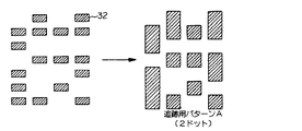
ここで、追跡用パターンA、B、Cと、本来の追跡用パターンとの関係について図7〜 図9を用いてそれぞれ説明する。追跡パターンAは、図7に示すように、本来の追跡用パターンを構成するドット領域32を副走査方向に2倍として2ドットにしたものであり、カラー複写機のトナーが何らかの理由で薄くなった状態に対する措置である。すなわち、トナーが薄いために、濃度を濃くするガンマ補正が行なわれる結果、追跡用パターンを構成するドット領域32の面積も広げられるが、それでもトナー自体が薄いために、追跡用パターンが識別性を発揮できす、スキャナ等で読み込めないおそれがある。このため、予め、追跡用パターンの濃度を濃くするような補正を行なっておくのである。この追跡用パターンAが選択されると、追跡用パターン付加回路203にあっては、レジスタ67に“1”が書き込まれ、ドット領域32が、副走査方向の長さを2倍にして、2ドットで構成するように変更される。
Here, the relationship between the tracking patterns A, B, and C and the original tracking patterns will be described with reference to FIGS. As shown in FIG. 7, the tracking pattern A is obtained by doubling the
追跡用パターンBは、図8に示すように、本来の追跡用パターンと同一である。これは、カラー複写機のトナーが正常であるため、追跡用パターンが付加された画像データを、ガンマ補正回路204によりガンマ補正するだけで、追跡用パターンが識別性と潜在性とを発揮できるからである。
The tracking pattern B is the same as the original tracking pattern as shown in FIG. This is because since the toner of the color copying machine is normal, the
追跡パターンCは、図9に示すように、本来の追跡用パターンを構成するドット領域32の面積を約70%としたものであり、カラー複写機のトナーが何らかの理由で濃くなった状態に対する措置である。すなわち、トナーが濃いために、濃度を薄くするガンマ補正が行なわれる結果、追跡用パターンを構成するドット領域32の面積も狭められるが、それでもトナー自体が濃いために、追跡用パターンが潜在性を発揮できず、肉眼で識別できてしまうおそれがある。このため、予め、追跡用パターンの濃度を薄くするような補正を行なっておくのである。この追跡用パターンCが選択されると、追跡用パターン付加回路203にあっては、レジスタ65の内容が書き換えれ、ドット領域32の座標条件が変更される。ただし、この場合において、ドット領域32の面積をむやみに小さくすると、ドット領域32が過小となって、スキャナ等で読みとれなくなるおそれがある。そこで、CPU60は、ドット領域32の面積が読取装置の分解能よりも小さくならないような制御を行なう。
As shown in FIG. 9, the tracking pattern C has a
このようにして、トナーパッチの濃度測定が行なわれると、ガンマ補正回路204によるガンマ補正の入出力特性を定めるルックアップテーブルが選択される一方、追跡用パターン付加回路203において画像データに重ね合わせられる追跡用パターンが定められる。そして、実際に、画像データに対して追跡用パターンが付加され、ガンマ補正されて、補正後の画像データに基づく画像形成が行なわれるのは、原稿を複写する旨の操作が行なわれた後である。そこで、以下、かかる複写操作が行なわれた場合の動作について説明する。
When the density of the toner patch is measured in this way, a look-up table that determines the input / output characteristics of the gamma correction by the
2−4:原稿の読込
まず、原稿を複写する旨を示す所定の操作がなされると、スキャナー部100によって原稿が読み込まれ、その内容が濃度データL*、a*、b*として出力されて、色変換部201から1ページ毎にY、M、C、Kの順に出力される。この画像データは、ガンマ補正回路202により、画像形成部400の濃度特性に合わせて濃度補正される。そして、濃度補正された画像データは、追跡用パターン付加回路203に供給される。
2-4: Reading of Original First, when a predetermined operation indicating that the original is to be copied is performed, the original is read by the scanner unit 100, and the content is output as density data L * , a * , b *. Are output from the
2−5:追跡用パターン付加回路の動作
次に、ガンマ補正された画像データは、追跡用パターン付加回路203におけるバッファメモリ51(図6参照)に一旦記憶される。そして、バッファメモリ51に画像データが記憶されると、出力処理が行われる。すなわち、CPU60からクロック回路70に制御信号が供給され、クロック回路70が動作状態になる。クロック回路70が動作状態になると、クロック回路70からビデオクロック信号V_CK、ラインシンク信号L_SYNCおよびページシンク信号P_SYNCが出力される。これらの信号によって他の構成要素が駆動されるのであるが、その動作は、追跡用パターンA、あるいはBならびにCが選択される場合で異なるため、以下場合を分けて説明する。
2-5: Operation of Tracking Pattern Addition Circuit Next, the gamma-corrected image data is temporarily stored in the buffer memory 51 (see FIG. 6) in the tracking
2−5−1:追跡用パターンBまたはCが選択される場合
この場合、追跡用パターンを構成するドット領域32、32、……を1つのドットにより構成すべく、レジスタ67に“0”がセットされる。このため、セレクタ50においては、AND回路75の出力信号が選択される。さて、カウンタ71においてはビデオクロック信号V_CKがカウントされ、その結果がアドレス信号としてバッファメモリ51に供給されるから、各画素毎の画像データがセレクタ52の入力端Aに順次供給される。ここで、カウンタ72、73の計数結果で特定された座標が記録領域の座標条件に合致しない場合、あるいはカウンタ76、77の計数結果で特定された座標がドット領域の座標条件に合致しない場合は、AND回路75から“0”信号が出力される。この“0”信号は、セレクタ50の入力端Aを介してそのままセレクタ52の選択入力端SELに供給されるから、バッファメモリ51に記憶された画像データが、ガンマ補正回路204に供給される。一方、上記各座標が記録領域の座標条件およびドット領域の座標条件にそれぞれ該当する場合は、AND回路75から“1”信号が出力される。この“1”信号がセレクタ50を介してセレクタ52の選択入力端SELに供給されると、レジスタ68に記憶されたカラーデータ(黄色)が、入力端Bを介してガンマ補正回路204に供給される。これにより、複写用紙30上の各ドット領域32、32、……の印刷色は、該カラーデータに基づいて黄色になる。なお、パターンCが選択される場合には、レジスタ65にセットされる座標条件が変更されて、ドット領域32、32、……の長さが主走査方向にそれぞれ70%にされる。
2-5-1: When the tracking pattern B or C is selected In this case, "0" is set in the
2−5−2:追跡用パターンAが選択される場合
この場合、追跡用パターンを構成するドット領域32、32、……を2つのドットにより構成すべく、レジスタ67に“1”がセットされる。このため、セレクタ50においては、OR回路80の出力信号が選択される。この場合、AND回路75から出力された“1”信号が、OR回路80およびセレクタ50の入力端Bを順次介して、セレクタ52の選択入力端SELに供給される。従って、複写用紙30上のドット領域32、32、……の印刷色は、上述した場合と同様に黄色になる。さらに、AND回路75から出力された“1”信号は、遅延回路79を介して遅延された後、OR回路80、セレクタ50を介してセレクタ52の選択入力端SELに供給される。この遅延時間はラインシンク信号L_SYNCの周期のn倍であるから、各ドット領域32に隣接し該ドット領域と同一の形状を有する領域(以下、拡張領域という)も、印刷色が黄色に設定される。なお、図5においては、ドット領域32に隣接した拡張領域34が示されている。
2-5-2: When Tracking Pattern A is Selected In this case, "1" is set in the
このようにして、追跡用パターン付加回路203では、トナーパッチによる濃度偏差平均値にしたがって、追跡用パターンA、B、Cのデータが、画像データに重ね合わせられて、ガンマ補正回路204に供給される。
In this manner, in the tracking
2−6:ガンマ補正
追跡用パターン付加回路203によって追跡用パターンのデータが付加された画像データがガンマ補正回路204に供給されると、トナーパッチの濃度測定により選択されたルックアップテーブルにしたがって、当該画像データが変換される。ここで、追跡用パターンの形状は、このガンマ補正によって識別性と潜在性とを失わないように、追跡用パターン付加回路203において予め補正されているので、ガンマ補正による濃度変換の結果、当該追跡用パターンが、肉眼で識別できたり、あるいはスキャナをもってしても読み取ることができない、という不都合が回避される。
2-6: Gamma Correction When the image data to which the tracking pattern data has been added by the tracking
2−7:画像形成
画像データがガンマ補正回路204により濃度変換されると、この変換された画像データにしたがって複写用紙30上に画像形成が行なわれる。すなわち、変換された画像データに基づいてレーザ駆動回路301が駆動され、感光体401において潜像処理および現像処理が行われる。一方、転写装置406には複写用紙が搬送され、この複写用紙に現像されたトナーが転写される。かかる潜像、現像および転写処理は各原色毎に行われ、各トナーが複写用紙に転写される。その後、各トナーは複写用紙に定着され、この複写用紙が排出される。
2-7: Image Formation When the image data is subjected to density conversion by the
3:変形例
上述した実施例においては、追跡用パターンを、トナーパッチの濃度偏差にしたがって補正したが、その補正内容は、追跡用パターンを構成するドット領域32の面積、およびドットの数を変更することであった。しかし、この発明は、上述した技術に限定されるものではなく、追跡用パターンの濃度を変更するものであれば、いかなるものでも良く、例えば、次のような種々の変形例が挙げられる。
3: Modification In the above-described embodiment, the tracking pattern is corrected according to the density deviation of the toner patch. The content of the correction changes the area of the
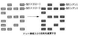
追跡用パターンを構成するドット領域32の色彩を変更する。トナーパッチが薄い場合には、図10に示すように、ドット領域32の色彩をイエローからシアンなどに変更して、追跡用パターンの濃度を濃くするように補正するのである。この場合には、図6におけるCPU60がレジスタ68にシアンのカラーデータをセットし、かかるシアン(C)の画像データが供給された場合に、追跡用パターンを付加すれば良い。
The color of the
追跡用パターンの間隔を変更する。トナーパッチが濃い場合には、図11に示すように、追跡用パターン(記録領域31)の間隔aを広げて間隔a'として、追跡用パターンを薄くするよう補正するのである。反対に、トナーパッチが薄い場合には、追跡用パターンの間隔を狭めて、追跡用パターンを濃くするように補正するのである。この場合にCPU60は、レジスタ64における記録領域31の座標条件を変更する。ただし、この場合において、記録領域31の間隔を無制限に広げると、切手等のような小面積の複写物内に追跡用パターンが含まれなくなって、コピーの部分的悪用を防止できなくなるおそれがある。そこで、CPU60は、かかる小面積に少なくとも1つの追跡用パターンが形成されるべく、記録領域31の間隔が所定値以上にならないような制御を行なう。
Change the interval of the tracking pattern. When the toner patch is dark, as shown in FIG. 11, the interval a of the tracking pattern (recording area 31) is increased to make the interval a ', so that the tracking pattern is corrected to be thin. Conversely, when the toner patch is thin, the interval between the tracking patterns is narrowed, and the correction is performed so that the tracking patterns are darkened. In this case, the
追跡用パターンを構成するドット領域32の間隔を変更する。トナーパッチが濃い場合には、図12に示すように、ドット領域32、32、……の間隔を広げて、記録領域31、31、……の面積を大きくするように補正するのである。すなわち、追跡用パターン自体を大きくするように補正するのである。反対に、トナーパッチが薄い場合には、ドット領域32、32、……の間隔を狭めて、記録領域31、31、……の面積を小さくするように補正するのである。すなわち、追跡用パターン自体を小さくするように補正するのである。ただし、追跡用パターン自体を無制限に大きくすると、隣接する追跡用パターンと重なりが生じるおそれがあるから、記録領域31の間隔も広げるように補正する。さらに、記録領域31の間隔を広げる場合には、上述した理由から所定値以上とならないように、補正する必要がある。CPU60は、これらを考慮して、レジスタ65とともにレジスタ64の内容を書き換え、記録領域31におけるドット領域32の座標条件とともに、複写用紙30上の記録領域の座標条件も変更する。
The interval between the
4:その他
上述した実施例あるいは変形例では、追跡用パターンを補正するに際し、追跡用パターンを構成するドット領域32のドット数、面積、色彩、間隔、あるいは追跡用パターン自体の大きさを単独で変更するようにしたが、これらの要素については、トナーパッチの濃度偏差平均値に応じて、複数個任意に組み合わせて、変更するようにしても良い。
4: Others In the above-described embodiment or modified example, when correcting the tracking pattern, the number of dots, the area, the color, the interval of the
203……追跡用パターン付加回路(発生手段)400……画像形成部(形成手段)411……演算装置(認識手段) 203: tracking pattern adding circuit (generating means) 400: image forming unit (forming means) 411: arithmetic unit (recognizing means)
Claims (5)
所定のトナー濃度に対応するトナーパッチ信号に基づいてトナーパッチを形成するトナーパッチ形成手段と、
前記トナーパッチ形成手段によって形成されたトナーパッチの濃度を測定するトナー濃度センサと、
前記トナー濃度センサにより測定されたトナーパッチの濃度と、予め決められたトナーパッチの濃度の目標値との差を認識する認識手段と、
前記認識手段により認識された濃度差に基づいて前記追跡用記録パターンの形状が前記濃度値の差に対応する形状となるように、前記トナーパッチ信号とは独立に前記追跡用パターン信号の補正を行う補正手段と、
前記補正手段により補正された追跡パターン信号および前記トナーパッチ信号とに基づいて記録画像を形成する形成手段と
を具備することを特徴とする画像処理装置。 Generating means for generating a tracking pattern signal for forming a tracking recording pattern;
Toner patch forming means for forming a toner patch based on a toner patch signal corresponding to a predetermined toner density;
A toner density sensor that measures the density of the toner patch formed by the toner patch forming unit;
Recognition means for recognizing a difference between the density of the toner patch measured by the toner density sensor and a predetermined target value of the density of the toner patch;
The correction of the tracking pattern signal is performed independently of the toner patch signal such that the shape of the tracking recording pattern has a shape corresponding to the density value difference based on the density difference recognized by the recognition unit. Correction means for performing;
An image processing apparatus comprising: a forming unit that forms a recorded image based on the tracking pattern signal corrected by the correcting unit and the toner patch signal.
Priority Applications (1)
| Application Number | Priority Date | Filing Date | Title |
|---|---|---|---|
| JP2004168454A JP2004289873A (en) | 2004-06-07 | 2004-06-07 | Image processing apparatus |
Applications Claiming Priority (1)
| Application Number | Priority Date | Filing Date | Title |
|---|---|---|---|
| JP2004168454A JP2004289873A (en) | 2004-06-07 | 2004-06-07 | Image processing apparatus |
Related Parent Applications (1)
| Application Number | Title | Priority Date | Filing Date |
|---|---|---|---|
| JP2000275643A Division JP2001144949A (en) | 2000-09-11 | 2000-09-11 | Image processing unit |
Publications (1)
| Publication Number | Publication Date |
|---|---|
| JP2004289873A true JP2004289873A (en) | 2004-10-14 |
Family
ID=33297126
Family Applications (1)
| Application Number | Title | Priority Date | Filing Date |
|---|---|---|---|
| JP2004168454A Pending JP2004289873A (en) | 2004-06-07 | 2004-06-07 | Image processing apparatus |
Country Status (1)
| Country | Link |
|---|---|
| JP (1) | JP2004289873A (en) |
Cited By (3)
| Publication number | Priority date | Publication date | Assignee | Title |
|---|---|---|---|---|
| JP2008299138A (en) * | 2007-05-31 | 2008-12-11 | Canon Inc | Image forming apparatus and its control method |
| US7646996B2 (en) | 2007-04-23 | 2010-01-12 | Canon Kabushiki Kaisha | Image forming apparatus and control method thereof |
| JP2017151135A (en) * | 2016-02-22 | 2017-08-31 | コニカミノルタ株式会社 | Image forming apparatus |
-
2004
- 2004-06-07 JP JP2004168454A patent/JP2004289873A/en active Pending
Cited By (5)
| Publication number | Priority date | Publication date | Assignee | Title |
|---|---|---|---|---|
| US7646996B2 (en) | 2007-04-23 | 2010-01-12 | Canon Kabushiki Kaisha | Image forming apparatus and control method thereof |
| JP2008299138A (en) * | 2007-05-31 | 2008-12-11 | Canon Inc | Image forming apparatus and its control method |
| US8213057B2 (en) | 2007-05-31 | 2012-07-03 | Canon Kabushiki Kaisha | Image forming apparatus and control method thereof |
| JP2017151135A (en) * | 2016-02-22 | 2017-08-31 | コニカミノルタ株式会社 | Image forming apparatus |
| US9846398B2 (en) | 2016-02-22 | 2017-12-19 | Konica Minolta, Inc. | Image forming apparatus |
Similar Documents
| Publication | Publication Date | Title |
|---|---|---|
| JP2009246949A (en) | Image forming apparatus, image forming method, and image forming program | |
| EP0515162B1 (en) | Image processing method and apparatus | |
| US20050275713A1 (en) | Synchronization signal generator and image forming apparatus | |
| JP6507881B2 (en) | Image forming apparatus and program | |
| JPH0939294A (en) | Image recording device | |
| JP2010113070A (en) | Image forming apparatus and control method | |
| EP2919452A1 (en) | Apparatus, image processing apparatus, and method | |
| JP4395743B2 (en) | Image forming apparatus and positional deviation correction method | |
| JP2001144949A (en) | Image processing unit | |
| JP2004289873A (en) | Image processing apparatus | |
| EP1788455B1 (en) | Method and system for improved control of xerographic parameters in a digital imaging system | |
| JPH08298588A (en) | Image processor | |
| EP0901277B1 (en) | Image processing apparatus and method | |
| JP3736185B2 (en) | Image processing device | |
| JP2010004133A (en) | Image forming apparatus and image processing method | |
| JP4135750B2 (en) | Image forming apparatus | |
| JP5981962B2 (en) | Image forming apparatus and control method thereof | |
| JP3288764B2 (en) | Image processing apparatus and method | |
| JP4058795B2 (en) | Image processing apparatus and image processing method | |
| JP3193098B2 (en) | Image processing apparatus and method | |
| JPH11284850A (en) | Image output device | |
| JP2005210469A (en) | Image controlling method and image-forming device | |
| JP3790877B2 (en) | Image processing device | |
| US20190191056A1 (en) | Image forming apparatus, image forming method, and storage medium | |
| US9111196B2 (en) | Image forming apparatus and image forming method |
Legal Events
| Date | Code | Title | Description |
|---|---|---|---|
| A977 | Report on retrieval |
Free format text: JAPANESE INTERMEDIATE CODE: A971007 Effective date: 20060201 |
|
| A131 | Notification of reasons for refusal |
Free format text: JAPANESE INTERMEDIATE CODE: A131 Effective date: 20060221 |
|
| A02 | Decision of refusal |
Free format text: JAPANESE INTERMEDIATE CODE: A02 Effective date: 20060711 |