JP2004284002A - Working control device - Google Patents
Working control device Download PDFInfo
- Publication number
- JP2004284002A JP2004284002A JP2003202592A JP2003202592A JP2004284002A JP 2004284002 A JP2004284002 A JP 2004284002A JP 2003202592 A JP2003202592 A JP 2003202592A JP 2003202592 A JP2003202592 A JP 2003202592A JP 2004284002 A JP2004284002 A JP 2004284002A
- Authority
- JP
- Japan
- Prior art keywords
- processing
- tool
- case
- unit
- cutting
- Prior art date
- Legal status (The legal status is an assumption and is not a legal conclusion. Google has not performed a legal analysis and makes no representation as to the accuracy of the status listed.)
- Pending
Links
Images


Classifications
-
- G—PHYSICS
- G05—CONTROLLING; REGULATING
- G05B—CONTROL OR REGULATING SYSTEMS IN GENERAL; FUNCTIONAL ELEMENTS OF SUCH SYSTEMS; MONITORING OR TESTING ARRANGEMENTS FOR SUCH SYSTEMS OR ELEMENTS
- G05B19/00—Programme-control systems
- G05B19/02—Programme-control systems electric
- G05B19/18—Numerical control [NC], i.e. automatically operating machines, in particular machine tools, e.g. in a manufacturing environment, so as to execute positioning, movement or co-ordinated operations by means of programme data in numerical form
- G05B19/4097—Numerical control [NC], i.e. automatically operating machines, in particular machine tools, e.g. in a manufacturing environment, so as to execute positioning, movement or co-ordinated operations by means of programme data in numerical form characterised by using design data to control NC machines, e.g. CAD/CAM
-
- G—PHYSICS
- G05—CONTROLLING; REGULATING
- G05B—CONTROL OR REGULATING SYSTEMS IN GENERAL; FUNCTIONAL ELEMENTS OF SUCH SYSTEMS; MONITORING OR TESTING ARRANGEMENTS FOR SUCH SYSTEMS OR ELEMENTS
- G05B19/00—Programme-control systems
- G05B19/02—Programme-control systems electric
- G05B19/18—Numerical control [NC], i.e. automatically operating machines, in particular machine tools, e.g. in a manufacturing environment, so as to execute positioning, movement or co-ordinated operations by means of programme data in numerical form
- G05B19/4093—Numerical control [NC], i.e. automatically operating machines, in particular machine tools, e.g. in a manufacturing environment, so as to execute positioning, movement or co-ordinated operations by means of programme data in numerical form characterised by part programming, e.g. entry of geometrical information as taken from a technical drawing, combining this with machining and material information to obtain control information, named part programme, for the NC machine
- G05B19/40937—Numerical control [NC], i.e. automatically operating machines, in particular machine tools, e.g. in a manufacturing environment, so as to execute positioning, movement or co-ordinated operations by means of programme data in numerical form characterised by part programming, e.g. entry of geometrical information as taken from a technical drawing, combining this with machining and material information to obtain control information, named part programme, for the NC machine concerning programming of machining or material parameters, pocket machining
- G05B19/40938—Tool management
-
- G—PHYSICS
- G05—CONTROLLING; REGULATING
- G05B—CONTROL OR REGULATING SYSTEMS IN GENERAL; FUNCTIONAL ELEMENTS OF SUCH SYSTEMS; MONITORING OR TESTING ARRANGEMENTS FOR SUCH SYSTEMS OR ELEMENTS
- G05B2219/00—Program-control systems
- G05B2219/30—Nc systems
- G05B2219/35—Nc in input of data, input till input file format
- G05B2219/35084—Geometric feature extraction, concave and convex regions, object recognition
-
- G—PHYSICS
- G05—CONTROLLING; REGULATING
- G05B—CONTROL OR REGULATING SYSTEMS IN GENERAL; FUNCTIONAL ELEMENTS OF SUCH SYSTEMS; MONITORING OR TESTING ARRANGEMENTS FOR SUCH SYSTEMS OR ELEMENTS
- G05B2219/00—Program-control systems
- G05B2219/30—Nc systems
- G05B2219/35—Nc in input of data, input till input file format
- G05B2219/35529—Monitoring current machining, store information in database as a new working case
-
- G—PHYSICS
- G05—CONTROLLING; REGULATING
- G05B—CONTROL OR REGULATING SYSTEMS IN GENERAL; FUNCTIONAL ELEMENTS OF SUCH SYSTEMS; MONITORING OR TESTING ARRANGEMENTS FOR SUCH SYSTEMS OR ELEMENTS
- G05B2219/00—Program-control systems
- G05B2219/30—Nc systems
- G05B2219/35—Nc in input of data, input till input file format
- G05B2219/35531—Operator inputs manually evaluation of current machining
-
- G—PHYSICS
- G05—CONTROLLING; REGULATING
- G05B—CONTROL OR REGULATING SYSTEMS IN GENERAL; FUNCTIONAL ELEMENTS OF SUCH SYSTEMS; MONITORING OR TESTING ARRANGEMENTS FOR SUCH SYSTEMS OR ELEMENTS
- G05B2219/00—Program-control systems
- G05B2219/30—Nc systems
- G05B2219/36—Nc in input of data, input key till input tape
- G05B2219/36284—Use of database for machining parameters, material, cutting method, tools
-
- G—PHYSICS
- G05—CONTROLLING; REGULATING
- G05B—CONTROL OR REGULATING SYSTEMS IN GENERAL; FUNCTIONAL ELEMENTS OF SUCH SYSTEMS; MONITORING OR TESTING ARRANGEMENTS FOR SUCH SYSTEMS OR ELEMENTS
- G05B2219/00—Program-control systems
- G05B2219/30—Nc systems
- G05B2219/36—Nc in input of data, input key till input tape
- G05B2219/36289—Cutting, machining conditions by optimisation of time, cost, accuracy
-
- G—PHYSICS
- G05—CONTROLLING; REGULATING
- G05B—CONTROL OR REGULATING SYSTEMS IN GENERAL; FUNCTIONAL ELEMENTS OF SUCH SYSTEMS; MONITORING OR TESTING ARRANGEMENTS FOR SUCH SYSTEMS OR ELEMENTS
- G05B2219/00—Program-control systems
- G05B2219/30—Nc systems
- G05B2219/36—Nc in input of data, input key till input tape
- G05B2219/36296—Order, select, determine, change machining sequence, order
-
- G—PHYSICS
- G05—CONTROLLING; REGULATING
- G05B—CONTROL OR REGULATING SYSTEMS IN GENERAL; FUNCTIONAL ELEMENTS OF SUCH SYSTEMS; MONITORING OR TESTING ARRANGEMENTS FOR SUCH SYSTEMS OR ELEMENTS
- G05B2219/00—Program-control systems
- G05B2219/30—Nc systems
- G05B2219/36—Nc in input of data, input key till input tape
- G05B2219/36352—Select tool as function of part shape, number of grooves and groove width
-
- G—PHYSICS
- G05—CONTROLLING; REGULATING
- G05B—CONTROL OR REGULATING SYSTEMS IN GENERAL; FUNCTIONAL ELEMENTS OF SUCH SYSTEMS; MONITORING OR TESTING ARRANGEMENTS FOR SUCH SYSTEMS OR ELEMENTS
- G05B2219/00—Program-control systems
- G05B2219/30—Nc systems
- G05B2219/36—Nc in input of data, input key till input tape
- G05B2219/36357—Tool line up, select right order of tool, optimal tool order loading, tool file
-
- G—PHYSICS
- G05—CONTROLLING; REGULATING
- G05B—CONTROL OR REGULATING SYSTEMS IN GENERAL; FUNCTIONAL ELEMENTS OF SUCH SYSTEMS; MONITORING OR TESTING ARRANGEMENTS FOR SUCH SYSTEMS OR ELEMENTS
- G05B2219/00—Program-control systems
- G05B2219/30—Nc systems
- G05B2219/49—Nc machine tool, till multiple
- G05B2219/49086—Adjust feeding speed or rotational speed of main spindle when load out of range
-
- Y—GENERAL TAGGING OF NEW TECHNOLOGICAL DEVELOPMENTS; GENERAL TAGGING OF CROSS-SECTIONAL TECHNOLOGIES SPANNING OVER SEVERAL SECTIONS OF THE IPC; TECHNICAL SUBJECTS COVERED BY FORMER USPC CROSS-REFERENCE ART COLLECTIONS [XRACs] AND DIGESTS
- Y02—TECHNOLOGIES OR APPLICATIONS FOR MITIGATION OR ADAPTATION AGAINST CLIMATE CHANGE
- Y02P—CLIMATE CHANGE MITIGATION TECHNOLOGIES IN THE PRODUCTION OR PROCESSING OF GOODS
- Y02P90/00—Enabling technologies with a potential contribution to greenhouse gas [GHG] emissions mitigation
- Y02P90/02—Total factory control, e.g. smart factories, flexible manufacturing systems [FMS] or integrated manufacturing systems [IMS]
Abstract
Description
【0001】
【発明の属する技術分野】
本発明は,コンピュータ上で定義された設計情報に基づいて加工機を制御し、被削材を加工して目的物を得る技術に関するものである。
【0002】
【従来の技術】
従来、CADデータ等に基づいて加工機を制御し、自動的に加工を行うようにした装置が知られている。例えば、最終的なワークの形状に関する加工形状データ、ワークの材質、形状に関するワークデータを入力し、工作機械のコラムやベッド等の機体特性を含んだ機械仕様データ、加工工具と、その工具がホルダに取り付けられた時の加工時における変形等を含んだ工具仕様データを格納したデータに基づき、ワーク加工工具経路を生成すると共に、工作機械の主軸回転速度、送り速度等の加工条件を決定する工具経路決定手段を有する工作機械の制御装置が提案されている。
【0003】
従来の装置では、一般に、3次元CADデータとデータベースとを用い、所定のアルゴリズムにより加工工程を決定することによって、自動化や標準化を実現している。この場合、データベースの内容は人間が変更しない限り自動的には更新されず、加工の結果がデータベースの内容に反映されない。また、システムから出力される加工工程の調整を行うためには、専門の知識を持つ人間がデータベースの調整を行う必要があった。
【0004】
これらの、データベースはいわゆる条件ライブラリが中心で、条件の最適化、加工現象の記憶といったオペレータが行う役割をシステム内に機能として持ち、これらの情報を最適に組合せて自動的にNCデータを生成するシステムは皆無であった。
【0005】
また、いわゆるフィードバック方式については、複数の加工品の寸法を測定し、その特定値の今回値と前回値の誤差を求め、補正をかけていく加工条件補正装置は存在するが、一つの加工品を切削中に主軸負荷やビビリなどの加工現象をモニタリングしながら加工機の送りや回転数をリアルタイム補正または次回加工時の切削条件補正に使用するものは存在しない。
【0006】
さらに従来の加工制御装置において、加工結果のデータベースへのフィードバックは、回転数や送り速度、加工時間、寸法精度など、測定して数値として表すことができるものを対象にしており、例えば寸法公差から測定値が外れていても他の部品との嵌合が良ければ合格とする場合や、樹脂成形品金型において成形部入れ子部品の表面粗さが指定値よりも粗くても成形品が離型できればいいといった場合など、オペレータの意思や判断を反映しない。
【0007】
また、従来、工具と工程は、オペレータの経験によって決定されている。現在、広く使用されている3次元CAMにおいて、どの工具をどの工程で使用するかは自動化されていない。
【0008】
なお、加工する製品の種別と、工具や工程とを対応付けて記憶したデータベースに基づいて加工工程を設計する機能をもったシステムは提案されているが、このようなデータベースを保有せずに、与えられた3D形状と保有する工具ライブラリから加工工程を設計するシステムはない。
【0009】
また、径の大きい順にその切削量や削り残しを計算し,小さい工具を決定していくシステムは存在するが、作業者が仕上で使用しようとする最小の工具径から使用すべき最大の工具径を算出するシステムはなく、少なからずとも作業者の経験が必要であった。
【0010】
【非特許文献1】
“型彫り工程設計支援システム”、株式会社データデザイン、[平成14年10月22日検索]
インターネット<URL:http://www.datadesign.co.jp/mill−plan/mill−plan1.htm>
【特許文献1】
特開2002−189510号公報 請求項1
【特許文献2】
特開平8−211919号公報 請求項1〜4
【特許文献3】
特開平4−106603号公報
【特許文献4】
特開2000−84794号公報
【特許文献5】
特開2002−116807号公報
【0011】
【発明が解決しようとする課題】
上記の装置においては、次の様な問題点が指摘されている。
(a)NCデータを作成する経験豊富なオペレータのノウハウが他のオペレータの切削条件に反映できないため、異なるオペレータ間で同じ失敗を繰り返す。
(b)NCデータを作成するオペレータの教育、養成に時間がかかる。
(c)NCデータを作成した結果はオペレータのノウハウにより異なり、加工状態に差が出る。
(d)切削加工条件は、紙に記載されるか、あるいは経験豊富なオペレータの記憶に残されるのが一般的であり、正確な保存や、他者による利用が困難である。
(e)加工機が変化すると、新たな加工ノウハウの蓄積が必要となる。
(f)最適な加工条件を導くため解析を行う加工システムは時間がかかりすぎ、時間がコストダウン・工程管理の重要ファクターである加工現場には不向きである。
(g)工具と工程を適切に決定できるかどうかはオペレータの経験に左右されるため、オペレータの経験の差によって、加工品質のバラツキや、非効率な切削、不適切な工具の使用といった問題が発生する。また加工する製品の種別と、工具や工程とを対応付けて記憶したデータベースを備えたシステムの場合、経験の少ないオペレータであってもある程度対処できるが、データベースにない形状については適切な工具及び工程決定ができない。従来、人間が工具を決定する場合、先ず、経験に基づいて荒加工に適切な径の工具を決定し、次いで中仕上げ用工具、仕上げ用工具と、工具径の大きい順に決定している。これをシステムに置き換え、径の大きい順に工具を決定する場合、使用可能な限り大きな径の工具から順に計算を行うので非効率である。
【0012】
本発明は、上記のような問題点を解決するためになされたものである。即ち、本発明は、加工を行う形状の特徴に応じて加工事例を検索し、この加工事例に基づいて加工条件を設定することにより、適切な加工条件での加工を可能とする技術の提供を目的とする。
【0013】
【課題を解決するための手段】
本発明は前記課題を解決するために、以下の手段を採用した。
【0014】
本発明の加工制御装置、加工制御プログラム及び加工制御システムは、目的物の設計データから3次元形状の特徴に関する形状情報を取得し、過去に行った加工の加工条件を加工事例として記憶する加工事例記憶部から前記形状情報に基づいて加工事例を索出し、前記事例検索部で検索した加工事例に基づいて加工条件を決定し、前記加工条件に基づいて加工機の制御を行う。
【0015】
これにより、本発明は、加工すべき目的物の設計データと、過去に行った加工事例との間に形状の類似性があれば、加工工具や加工工程、更には加工中の切削工具の挙動や加工結果にも類似性があることに着目し、加工事例を蓄積して、形状の特徴に基づいて検索し、この加工事例に基づいて加工条件を決定したことにより、過去の加工結果を利用できるようにしている。即ち、経験の少ないオペレータであってもデータベースに蓄積された過去の例に基づいて加工を行うことができる。また、過去の加工データとしては、切削加工後の成功事例と共に失敗事例も蓄積可能なため、類似の失敗を繰り返すことを無くすことができる。
【0016】
【発明の実施の形態】
以下、本発明の実施形態である加工システムを図1から図35の図面に基づいて説明する。
【0017】
〈システム構成〉
図1は、本実施形態の加工システムの構成を示すブロック図である。
【0018】
本実施形態の加工システムは、加工制御装置1と、この加工制御装置1に制御される加工機2とからなっている。
【0019】
§1.加工制御装置
加工制御装置1は、加工前入力部11、3次元形状特徴抽出部(形状特徴抽出部に相当)12、事例検索部13、切削加工条件自動設定部(加工条件設定部に相当)14、切削加工事例データベース(加工事例記憶部に相当)15、判断基準データベース(判断基準記憶部に相当)16、加工事例登録部17、加工後入力部18、自動NCデータ作成部(制御部)19、モニタリング部10を備えている。
【0020】
この加工前入力部11は、キーボードやタッチパネルなどの操作部であり、オペレータに操作され、目的物に関する情報(目的物情報)の入力を受け付ける。該目的物に関する情報とは、被削材の種類や硬度など、加工に必要なデータのうち、設計データに含まれていない情報である。
【0021】
3次元形状特徴抽出部12は、目的物の3次元CADデータ(設計データに相当)から後述のように3次元形状の特徴に関する形状情報を取得する。
【0022】
事例検索部13は、上記3次元形状特徴抽出部12で取得した形状情報に基づいて切削加工事例データベース15から加工事例を索出する。
【0023】
切削加工条件自動設定部14は、前記事例検索部13で検索した加工事例に基づいて加工条件を決定する。
【0024】
切削加工事例データベース15は、過去に行った加工の加工条件を加工事例として記憶する。
【0025】
判断基準データベース16は、加工条件の判断基準となる情報として、加工条件閾値データベース16aや、工具ライブラリ16b、切削条件データベース16c等を記憶している。
【0026】
加工事例登録部17は、前記モニタリング部10で取得した加工機2の情報を加工事例として形状情報と対応づけて加工事例記憶部に記憶させる。
【0027】
加工後入力部18は、キーボードやタッチパネルなどの操作部であり、オペレータに操作され、前記加工の良否に関する情報の入力を受け付ける。なお、本実施形態において、加工前入力部11と加工後入力部18は、1つのキーボードで兼用されている。
【0028】
自動NCデータ作成部19は、前記切削加工条件自動設定部14で設定された加工条件に基づいて加工機2の制御を行う。
【0029】
モニタリング部10は、前記自動NCデータ作成部19が前記加工条件に基づいて制御を行ったときの加工機2の情報を取得する。
【0030】
加工制御装置1は、上述の各部10〜19として専用に設計された電子回路(ハードウェア)から構成された専用の電子機器であっても良いし、汎用のコンピュータで上記各部10〜19の機能をソフトウェアで実現した装置であっても良い。
【0031】
なお、本実施形態の加工制御装置1は、図2に示すように、一般的なコンピュータである。
【0032】
同図に示すように、加工制御装置1は、本体31内にCPU(central processing unit)やメインメモリ等よりなる演算処理部32、演算処理の為のデータやソフトウェアを記憶した記憶装置(ハードディスク)33、入出力部(I/O)34等を備えている。
【0033】
入出力部34は、キーボード(加工前入力部11、加工後入力部18)やマウス等の入力デバイス、表示装置やプリンター等の出力デバイス、他の機器との情報の送受信を行うインターフェイスが適宜接続される。
【0034】
記憶装置33には、オペレーティングシステム(OS)やアプリケーションソフト(加工制御プログラム)がインストールされている。また、該記憶装置33内には、切削加工事例データベース15や、判断基準データベース16が構築されている。
【0035】
演算処理部32は、該加工制御プログラムに従って演算処理を行うことにより、3次元形状特徴抽出部(形状特徴抽出部に相当)12、事例検索部13、切削加工条件自動設定部14、加工事例登録部17、自動NCデータ作成部19、モニタリング部10として機能する。
【0036】
§2.加工機
本実施形態の加工機2は、切削加工部21や、加工機制御部22、マガジン23を備えている。
【0037】
この切削加工部21は、被削材を取り付ける設置台や、切削工具、この工具を取り付ける主軸、主軸の回転駆動部、X軸,Y軸,Z軸方向の送りを行う送り駆動部等からなり、被削材の切削加工を行う。
【0038】
加工機制御部22は、NCデータに基づいて切削加工部21の制御を行う。この加工機制御部22は、加工機2の加工状態を検出するセンサユニット22aや、該センサユニット22aで検出した加工状態やNCデータに応じて切削加工部21の制御を行う切削制御部22b、マガジンに収納されている工具の情報の取得や工具の交換を指示するマガジン管理部22c等を備えている。
【0039】
マガジン23は、切削加工部21で使用する工具を収納している。また、マガジン23は、前記NCデータに応じて切削加工部21で使用する工具を交換する機能(ATC)を有している。
【0040】
〈加工手順〉
次に上記システムにおける加工制御手順を図3〜図35を用いて説明する。
【0041】
§1.基本手順
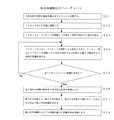
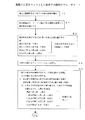
加工制御装置1は、目的物の3次元CADデータ100が入力されると、図3に示すように、ステップS1にて3次元形状特徴抽出部12が該3次元CADデータ100から3次元形状の特徴に関する形状情報を取得する。
【0042】
また、ステップS2にてオペレータが加工前入力部11を操作して被削材の種類や硬度などの目的物情報を入力すると、加工前入力部11がこの入力を受け付けて事例検索部13に入力する。
【0043】
次のステップS3では、事例検索部13が、前記形状情報を検索キーとして切削加工事例データベース15から加工事例を索出する。
【0044】
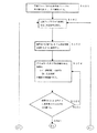
次のステップS4では、切削加工条件自動設定部14が、ステップS3で加工事例が得られたか否かを判断し、得られればステップS5へ移行し、この加工事例と判断基準データベース16の情報とに基づいて加工条件を決定する。また、ステップS3で加工事例が得られなければ、ステップS6へ移行し、切削加工条件自動設定部14が、前記3次元形状特徴抽出部12で求めた形状情報と、加工前入力部11で受け付けた情報と、判断基準データベース16の情報とに基づいて切削加工条件を決定する。ここで、判断基準データベース16の切削条件データベース16cには、予め3次元形状や被削材の種類に応じた加工条件のメーカー推奨値やデフォルト値を記憶させている。切削加工条件自動設定部14は、加工事例が得られない場合、形状情報等に応じてメーカー推奨値やデフォルト値を参照して加工条件を決定する。
【0045】
次のステップS7では、自動NCデータ作成部19が前記切削加工条件自動設定部14で決定した加工条件に基づいてNCデータを作成し、I/O34のインターフェイスを介して加工機2へ該NCデータを送信する。一方、加工機2は、このNCデータに基づいて切削加工を行う。
【0046】
次のステップS8では、モニタリング部10が、センサユニット22aで検出した情報を受信して加工機2における加工状況をモニタリングしている。
【0047】
自動NCデータ作成部19は、ステップS9にて、加工制御が終了したか否かを判断し、終了していなければ、ステップ7,8を繰り返し、終了すればステップS10に移行する。
【0048】
ステップS10では、加工事例登録部17が、モニタリング部10で検出された情報(加工条件)を加工事例として、この加工を行う際に切削加工条件自動設定部14に入力された形状情報や加工前入力部11から入力された情報と対応付けて切削加工事例データベース15に登録する。
【0049】
このように、本実施形態の加工制御装置1は、加工事例に基づいて加工条件を決定しているため、経験の少ないオペレータであっても経験者と同等の加工が行えるようにしている。また、該加工制御装置1は、加工した結果を切削加工事例データベース15に登録するため、加工結果を他の人と共有できるようにしている。
【0050】
§2.加工手順の詳細
次に上記加工手順の詳細について説明する。これらの手順は、かならずしも全ての手順を実行しなければならないものではなく、上記加工システムにおいて加工する際に必要な手順を任意に組み合わせて実行すればよい。
【0051】
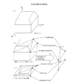
2−1.[最大外形寸法の抽出]
図4は、3次元形状特徴抽出部12が前記ステップS1にて3次元CADデータ100から形状情報として最大外形寸法を抽出する手順の説明図である。
【0052】
3次元形状特徴抽出部12は、3次元CADデータ100に基づき、図5(a)に示すように3次元モデル(目的物)の表面を微少な多角形(本例では3角形、以後ファセットと称す)に分割し(ステップS11、以下S11のように略記する)、その後、ファセットの3つの頂点について、図5(b)に示すように3次元CADの座標情報よりX座標、Y座標、Z座標(Fn(Xn,Yn,Zn)、Fn+1(Xn+1,Yn+1,Zn+1)、Fn+2(Xn+2,Yn+2,Zn+2)・・・)を取得し、同様な計算を全てのファセットについて繰り返し行う(S12〜14)。3次元形状特徴抽出部12は、全ファセットの頂点のX座標、Y座標、Z座標を取得して、全てのファセットの頂点座標を比較し、最小となるX座標、Y座標、Z座標と、最大となるX座標、Y座標、Z座標を取得する(S15,16)。
【0053】
3次元形状特徴抽出部12は、上記で求めた最大X値から最少X値を減算し、同様にY座標、Z座標についても計算を行うことにより(S17)、図6に示すように3次元モデルの最大X方向長さ、最大Y方向長さ、最大Z方向長さを求め最大外形寸法(形状情報)とする(S18)。
【0054】
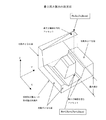
2−2.[除去体積の算出]
図7は、3次元形状特徴抽出部12が前記ステップS1にて3次元CADデータ100から形状情報として除去体積を求める手順の説明図である。
【0055】
3次元形状特徴抽出部12は、3次元CADデータ100に示される3次元モデル(図8(a))の表面を図8(b)のようにファセットに分割し(S21)、この後、各ファセットを図8(c)のようにXY平面すなわち加工機への取り付け面に投影して三角形を作成し(S22)、ファセットとファセットをXY平面に投影した三角形の相応する頂点とを結び(S23)、ファセットの3辺と、ファセットをXY平面に投影した三角形の3辺と、ファセットとファセットをXY平面に投影した三角形の相応する頂点とを結んだ3線とで構成される3角柱(図6(d))の体積を求め(S24)、これを繰り返して全ファセットについて求め(S25)、この体積の総和すなわち3次元モデルの体積を算出する(S26)。
【0056】
このように、図9(a)の3次元モデル91について体積を算出した後、上記の如くX方向最大長さ、Y方向最大長さ、Z方向最大長さをこの3切削加工部21について求め、このX方向最大長さ、Y方向最大長さ、Z方向最大長さを乗算してモデル最大外形体積を求め(S27)、この最大外形体積から3切削加工部21の体積を減算し、図9(b)に示すように切削加工で除去される体積を求める(S28)。
【0057】
2−3.[面情報の算出]
図10は、3次元形状特徴抽出部12が前記ステップS1にて3次元CADデータ100から形状情報として面情報を求める手順の説明図である。
【0058】
3次元形状特徴抽出部12は、3次元CADデータ100に基づき、3次元加工形状の表面をファセットに分割し(S31)、その後、図11のように、全てのファセットの法線ベクトルを求める(S32)。3次元形状特徴抽出部12は、このファセットの法線ベクトル(向き)がZ軸すなわち加工軸と平行か否かを判断し(S33)、平行であるファセットについてのみ、ファセットの面積とZ値を取得し(S34,S35)、Z値毎に面積を分類して(S36)、XY平面に平行なフラット面についてのZ値別での面情報を取得する(S37)。なお、ステップS33で法線ベクトルが加工軸と平行でないと判断したファセットは本情報から除外する(S38)。
【0059】
これにより、3次元モデル中の加工軸に対して垂直な面、即ちフラットエンドミルで加工できる面について、Z軸方向の位置毎の面積、即ち一度に加工できると推定される面積が求められ、切削加工条件自動設定部14が、加工条件を決定する際、この面情報に基づいて、面積が大きければ大きな径の工具を選択し、面積が小さければ小さな径の工具を選択する。
【0060】
2−4.[最小凹形状半径寸法の算出]
図12は、3次元形状特徴抽出部12が前記ステップS1にて3次元CADデータ100から形状情報として最小凹形状半径寸法を求める手順の説明図である。
【0061】
3次元形状特徴抽出部12は、3次元CADデータ100に基づき、3次元モデルの表面を平面とそれ以外の面、すなわち曲面に分類し(S41)、曲面の表面を抽出して(S42)、それ以外を本情報から除外する(S48)。
【0062】
そして3次元形状特徴抽出部12は、図13(a)に示すように3次元モデル作成時の誤差許容値間隔でU方向、V方向にそれぞれ分割し(S43)、U方向、V方向のそれぞれ隣り合う分割線の交点3個により、半径を取得し(S44)、取得した半径の中心から外側に向かう法線ベクトルのZ成分の方向を求め(S45)、このZ成分の向きが−Z方向と一致するか否かを求め(S46)、一致しなければ凸形状半径と判断して本情報から除外し(S49)、一致すれば凹形状半径と判断し(S46)、このうち最小となる凹形状半径を求める(S47)。
【0063】
これにより切削加工条件自動設定部14が、加工条件を決定する際、この最小凹形状半径寸法に基づいて、仕上げに使用する工具の径を求める。
【0064】
2−5.[最多凹形状半径寸法の算出]
図14は、3次元形状特徴抽出部12が前記ステップS1にて3次元CADデータ100から形状情報として最多凹形状半径寸法を求める手順の説明図である。
【0065】
3次元形状特徴抽出部12は、前述と同様に凹形状を有する面(図15(a))を取得し(図12のS41〜S46)、このうち図15(b)に示すように向かい合い、大きさが同一で、かつ法線ベクトルの向きが一致する辺と2直線にて構成される面と、図15(c)に示すように法線ベクトルの交点が存在する1組の向かい合う辺と、法線ベクトルの交点が存在し、かつ半径が同一の向かい合う1組の辺から構成される面と、図15(d)に示すように4つの辺の法線ベクトルの交点が存在する面を求め(S51)、これらの面の面積を算出し(S52)、これらの面を半径の大きさ別に分類する。但し、図15(c)に示す面は、同一の大きさが存在する半径で分類する(S53)。
【0066】
そして、3次元形状特徴抽出部12は、この分類された半径の大きさ毎に面積を求め、面積が最大となった半径の大きさを最多凹形状半径寸法として求める(S54)。
【0067】
これにより切削加工条件自動設定部14が、加工条件を決定する際、この最多凹形状半径寸法に基づいて、仕上げ前に使用する工具の径を求める。
【0068】
2−6.[最大深さの算出]
図16は、3次元形状特徴抽出部12が前記ステップS1にて3次元CADデータ100から形状情報として最大深さを求める場合の説明図である。
【0069】
3次元形状特徴抽出部12は、3次元CADデータ100に基づき、3次元モデルの表面をファセットに分割し、その後、図16に示すように、切削加工機2のXY平面に対して垂直で、かつ切削加工機2の取り付け面と接する(Z軸値が一致する)面または円弧を含む面と、切削加工機Aへの取付面を除く面とを構成するファセットについて、頂点のZ軸値を取得し、Zmaxすなわち最大Z軸値と、Zminすなわち最小Z軸値との差を最大深さとして求める。
【0070】
これにより切削加工条件自動設定部14が、加工条件を決定する際、この最大深さに応じ、被削材と干渉しない長さの工具を選択する。
【0071】
2−7.[切削範囲境界線の算出]
図17は、3次元形状特徴抽出部12が前記ステップS1にて3次元CADデータ100から形状情報として切削範囲境界線を求める場合の説明図である。
【0072】
3次元形状特徴抽出部12は、3次元CADデータ100に基づき、3次元モデルの表面をファセットに分割し、このファセットの法線がXY平面と垂直すなわち加工軸と平行であるか否かを判断し、平行であるファセットから構成される面と、平行でないファセットを含む面とに分類する。
【0073】
そして、各分類についてエッジを共有する面をグループ化して加工範囲として求め、各グループの中で他の面と共有していないエッジを加工範囲境界線として求める。例えば図17において、面41,42,43がグループ化され、このグループの中で他の面と共有していないエッジ、即ち太線で示すグループの外周を加工範囲境界線として求める。
【0074】
これにより切削加工条件自動設定部14が、加工条件を決定する際、この加工範囲境界線、加工範囲を決定する。また、切削加工条件自動設定部14は、この加工範囲となった面が、加工軸に対して垂直な面か否かによって、フラットエンドミルで切削するか、ボールエンドミルで切削するかを決定する。
【0075】
2−8.[ブランク寸法の算出]
図18は、3次元形状特徴抽出部12が前記ステップS1にて3次元CADデータ100から形状情報としてブランク寸法を求める場合の説明図である。
【0076】
3次元形状特徴抽出部12は、前記2−1の項と同様に図4に示す手順で最大外形寸法をX方向、Y方向、Z方向についてそれぞれ求める(S11〜S18)。そして3次元形状特徴抽出部12は、外形寸法が最も近い過去の切削加工事例を加工事例データベース15から検索し、この過去の加工事例から、削り代を求め(S61)、前記最大外形寸法に求めた削り代を付加してブランク寸法を仮決定し(S62)、切削加工機2の最大加工可能寸法と比較し(S63)、切削加工機2での加工が可能であると判断した場合に(S64)、図19に示すように仮決定したブランク寸法をブランク寸法に決定する(S65)。
【0077】
3.[過去の加工実績に基づく加工条件の決定]
加工事例データベース15には、3次元形状特徴抽出部12により抽出した、最大外形寸法(X,Y,Z)、除去体積、面情報(加工XY平面に平行な平面か非平面か)、最多凹形状半径寸法、最小凹形状半径寸法、最大深さ寸法と切削加工工程手順、切削加工工具種類、設定主軸回転数、送り速度、送りピッチ、Z切り込み量、加工工具軌跡などの切削加工条件と、実際に切削加工を行った時の実主軸回転数、実送り速度、加工中の主軸負荷、実切削時間、加工中に発生する各種物理現象の情報と、オペレータが判断した切削加工の良否判定の情報が一つの加工事例ごとに蓄積されている。なお、図20は、この加工事例データベース15の概念図である。
【0078】
事例検索部13は、上述のように3次元形状特徴抽出部12によって求めた最大外形寸法、除去体積、面情報、最多凹形状半径寸法、最小凹形状半径寸法、最大深さ等の形状情報をもとに、図21に示すように、この切削加工事例データベース15から、類似した形状の加工事例を検索する。
【0079】
例えば、検索条件が最大外形寸法の場合、3次元モデルのX軸最大長さと加工事例のX軸最大長さとを比較して寸法差を絶対値で求め、同様にY軸方向の寸法差、Z軸方向の寸法差について求め、XYZ軸方向全てが予めシステムで決められた値(δ)以下であれば、最大外形寸法は類似形状を持つと見なす。
【0080】
また、検索条件が除去体積の場合、3次元モデルと過去の加工事例の除去体積(切削加工体積)の差を求め、その絶対値が予めシステムで決定している値(δV)以下である場合に除去体積が類似と見なす。
【0081】
検索条件が面情報の場合、3次元モデルと加工事例のXY平面に平行な平面の面積の差を求め、その絶対値が予めシステムで決定している値(δA)以下である場合に面情報が類似と見なす。
【0082】
検索条件が最多凹形状半径寸法の場合、3次元モデルと過去の加工事例の最多凹形状半径寸法の差を求め、その絶対値が予めシステムで決定している値(δR)以下である場合に最多凹形状半径寸法が類似と見なす。
【0083】
検索条件が最小凹形状半径寸法の場合、3次元モデルと過去の加工形状との最小凹形状半径寸法の差を求め、その絶対値が予めシステムで決定している値(δMR)以下である場合に最小凹形状半径寸法が類似と見なす。
【0084】
検索条件が最大深さの場合、3次元モデルと過去の加工事例との最大深さ寸法の差を求め、その絶対値が予めシステムで決定している値(δD)以下である場合に最大深さ寸法が類似であると見なす。
【0085】
事例検索部13がこれらの検索条件を満足する加工事例を索出し、この加工事例の加工の良否に関する情報が良であった場合、切削加工条件自動設定部14は、この加工事例として記憶されている加工工程数や、使用加工工具、送り速度、主軸回転数などに基づいて切削加工条件を決定する。
【0086】
なお、切削加工条件自動設定部14は、切削加工時間の短縮化や、加工精度の向上のため、後述のように切削加工条件の最適化を行っても良い。
【0087】
4−1.[加工面粗さによる切削ピッチ及びZ切り込み調整]
切削加工事例データベース15に加工事例が少ない場合や、加工事例の無い被削材、切削加工工具とその組合せが検索結果として無く、且つ切削加工工具にボールエンドミルを使用する事を前提とした場合、切削加工条件自動設定部14は、切削条件データベース16cに記憶された標準値や加工前入力部11からオペレータが指示した値に基づいて切削加工条件を決定する。
【0088】
このとき理論面粗さは、図22に示すように、スカラップ高さをH、送りピッチをP、加工工具半径(ここでは,ボールエンドミル)をRとした時、H=R−(R2−P2/4)1/2で表されるから、上記切削加工条件の仕上げ加工工具と送りピッチを与えることでスカラップ高さH、すなわち理論面粗さが求められる。
【0089】
従って、上記切削加工条件で求められる加工面の粗さは、この理論面粗さとなる。しかし、実際に加工を行うと、被削材の種類や送り速度などによって実際の加工面の粗さ(実加工面粗さ)は異なってしまう。
【0090】
このため切削加工条件自動設定部14は、求める加工面の粗さが得られるように図23の如く加工条件閾値データベース16aに基づいて再計算を行う。
【0091】
なお、該加工条件閾値データベース16aは、切削実験や切削事例や加工工具メーカーから提供される加工データ等により、実加工面粗さと、この粗さとなる場合の加工条件との対応関係を求めて、記憶したものである。
【0092】
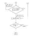
先ず切削加工条件自動設定部14は、理論粗さを求め(S71)、この理論面粗さに所定の許容値を付加し、許容値の範囲にある実加工面粗さを加工条件閾値データベース16aの中から検索する(S72)。
【0093】
そして切削加工条件自動設定部14は、前記理論粗さと実加工面粗さとが一致しなければ、次の候補の工具で再検索を行い(S73)、一致すればその加工例の切削工具、被削材、主軸回転数、送り速度、送りピッチ、実際の加工面粗さのデータを取得する。更にこのデータより切削加工工具の周速と一刃あたりの送り量を計算によって求める。次にこの算出値と新規加工形状に使用する加工工具の直径から主軸回転数と送り速度を計算によって求め、この結果を新規切削形状の切削条件とする(S74)。
【0094】
これにより、加工事例が無い新規形状においても、求める加工面粗さが得られる切削加工条件を自動で出力することが可能となる。
【0095】
4−2.[主軸負荷を考慮した制御]
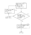
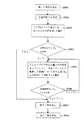
図24は、前記ステップS7〜S9にて加工時の主軸負荷をモニタリングし、適切な加工を行うように制御する手順を示している
自動NCデータ作成部19は、切削加工条件自動設定部14からの切削加工条件に基づいて作成したNCデータを加工機2に送信して加工を開始させ、同時にモニタリング部10で加工機2の加工状態(各種物理状態)をリアルタイムで計測している。このとき、主軸負荷が異常に増加すると、加工機2の破損や切削加工物の不良を招くので、自動NCデータ作成部19は、この主軸負荷が適正となるように制御を行う。
【0096】
先ず、自動NCデータ作成部19は、加工機制御部22又は判断基準データベースから主軸負荷上限値や適正値を取得する(S81)。
【0097】
また、自動NCデータ作成部19は、NCデータを加工機2へ送信して加工を開始させ(S82)、モニタリング部10から主軸負荷を取得する。
【0098】
このときモニタリング部10は、主軸を駆動する電動機の駆動電流値(主軸動力P)をセンサユニット22aで検出し、下記の式1を用いてこの電流値から実際の送り速度を算出している(S83)。
【0099】
t*f=(6120*P*n)/(k*v) ・・・(式1)
但し、
t:ピッチ(または切込み,mm),f:送り速度(mm/min),P:主軸動力(kW)
n:工作機械効率(≒0.8),k:比切削抵抗(被削材により異なる)
v:切削速度(工具周速,m/min)
自動NCデータ作成部19は、加工が終了したか否かを判断し(S84)、終了していなければ、主軸負荷STRが適正値STと等しいか否かを判断し(S85)、等しければステップS82に戻して加工を継続し、等しくなければ、等しくなる主軸動力(主軸電動機出力)Pを求め(S86)、この主軸動力Pとなる送り速度を式1から求め(S87)、この送り速度となるNCデータを加工機2へ送信する(S82)。
【0100】
そして加工が終了したと判断した場合(S84)、加工事例登録部17は、加工条件の送り値をSTR=STとなったときの送り値に変更して切削加工事例データベース15に登録する(S88)。
【0101】
これにより設定した加工条件が適切でなかった場合にも、リアルタイムに送り速度を制御して加工機2の破損や目的物の不良を防止できる。
【0102】
また、この加工結果を加工実績として登録するので、次回加工時には、初めから適正な値で加工を行うことができる。
【0103】
更に、このモニタリングして制御する値は、送り速度に限らず、主軸回転数や、Z切り込み量、送りピッチ等でも良い。またこれらを単独に制御するのでなく、送り速度の制御の次に主軸回転数を制御し、次にZ切り込み量の制御、次に送りピッチの制御等の様に制御項目を全項目に渡って、制御することも可能である。
【0104】
5−1.[切削範囲に基づく工具径の決定]
図25〜図27は、前記2−7の項で求めた切削範囲境界線に基づいて工具径を求める場合の説明図である。
【0105】
切削加工条件自動設定部14は、前述の如く切削範囲境界線を取得すると(S101)、工具ライブラリ16bを参照し、該ライブラリ16bに登録されている加工工具を直径の昇順または降順で選択し(S102)、図25に示すように切削範囲境界線の任意の点51で接触するように配置する(S103)。そして切削加工条件自動設定部14は、この境界線上を点51にて常に接するように加工工具を移動させ(S104)、点51以外で境界線と工具が接する点が存在するか否かを調べ(S105)、存在するならば、その点と加工工具中心を結ぶ直線K1と、境界上の点での法線K2とのなす角度が180°であるか否かを判断する(S106)。
【0106】
そして、切削加工条件自動設定部14は、この角度が180°以外の角度を持つ場合に干渉するとみなし、ステップS102に戻って工具ライブラリより次の工具を選択して処理を繰返し、一方、この角度が180°ならば干渉がなく使用可能であると判断し(S107)、干渉しない最も大きな加工工具径を得るまでこの処理を繰り返す(S108)。
【0107】
5−2.[切削深さに基づく工具突き出し量の決定]
図28は、前記2−6の項で求めた切削深さに基づいて工具突き出し量を求める場合の説明図である。
【0108】
切削加工条件自動設定部14は、前述の如く切削範囲境界線を取得すると(S91)、この最大深さから最低必要な突き出し量Lを求め(S92)、工具ライブラリ16bを参照し、この最低突き出し量を超え、且つ短い突き出し量または全長を持つ切削加工工具を工具ライブラリより選択し(S93)、図29のように切削加工工具の直径等から指定される指定ホルダ形状と組み合わせた場合に(S94)、3次元モデルとこのホルダ付き切削加工工具とが干渉するか否かのチェックを行い(S95)、干渉がなければ使用可能とみなし(S96)、干渉があれば使用不可能とする。
【0109】
使用不可能な場合には、次に最大深さに近く、且つ短い突き出し量または全長の工具を工具ライブラリから検索し、同様に指定ホルダを組合せて干渉チェックを行う。
【0110】
切削加工条件自動設定部14は、この加工工具選択、指定ホルダ取り付け、干渉チェックの繰り返しにより加工深さにあった加工工具を選択する。
【0111】
5−3.[面情報に基づく工具種類の決定]
図30は、前記2−3の項で求めた面情報に基づいて加工工具の種類を求める場合の説明図である。
【0112】
切削加工条件自動設定部14は、前述の如く面情報を取得し、XY平面に平行な平面と、そうでない面とに分類する。そして切削加工条件自動設定部14は、XY平面に平行な平面を加工する工具として、フラットエンドミルかブルノーズを工具ライブラリ16cから選択し、加工座標のXY平面に平行でない平面及び非平面を加工する工具としてボールエンドミルを工具ライブラリ16cから選択する。
【0113】
6.[工具寿命又は破壊の検知]
図31,図32は、工具寿命又は破壊を検知する手順の説明図である。
【0114】
自動NCデータ作成部19で自動作成されたNCデータが加工機制御部22へ送信され、切削加工機2が加工を開始すると、モニタリング部10がセンサユニット22aで検出した値に基づいて加工中の各種物理状態をリアルタイムで計測する。
【0115】
自動NCデータ作成部19は、このモニタリング部10でモニタした物理現象の内、加工工具材質が破壊する時に発生する超音波に応じて、リアルタイムに切削加工条件を制御して破壊の回避を行うか、あるいは切削加工後に切削条件データベース16cを変更し、次回の切削加工条件を制御するものである。
【0116】
切削加工条件をリアルタイムに制御する場合、自動NCデータ作成部19は、図31に示すように、先ずモニタリングを開始し(ステップA1、以下A1のように略記する)、単位時間当たりの加工工具材料固有な超音波の量が所定値以上であるか否かや、該超音波発生数の総数が所定値以上であるか否かを判断し(A3)、この所定値、即ち予め加工実験や切削加工の経験により決められた加工工具の異常磨耗・破壊現象と予測できる値を越えた場合(A2がYES)、もしくは切削加工中の超音波の発生数が加工工具の寿命および破壊の直前となる値を越えた場合(A3がYES)、切削加工機2あるいは加工機制御部22を経由して切削加工機2に切削加工条件を変更した指令(NCデータ)を送信する。
【0117】
ここで、切削加工条件の変更が、送り速度の変更とされている場合(A4がYES)、送り速度を予め決められた割合などで一定値下げる指令を切削加工機2あるいは加工機制御部22を経由して切削加工機2に出力し、これを前記超音波の発生数が所定値以下となるまで行う(A5)。例えば、F1000で送り速度が設定されている場合、F900となるようにする。それでも、工具の超音波の発生数が抑制出来ない場合は、更にF800、F700・・・と切削加工中に段階的に下がっていくようにする。
【0118】
また、切削条件の変更が主軸回転数の変更とされている(A4がNO)場合、主軸回転数を予め決められた割合などで一定値下げる指令を切削加工機2あるいは加工機制御部22を経由して切削加工機2に出力(A6)し、更に単位時間あたりの超音波の量を計測して、主軸回転数を決定することを繰り返し、超音波の発生数が所定値以下となるまで行う。
【0119】
また、切削加工後に切削条件データベース16cを変更する場合は、図32に示すように、切削加工中の切削条件は変化させず、初めのNCデータ通りの切削加工を行い、モニタリングした異常磨耗・破壊現象に係る超音波の発生数は、記憶装置33に一時記憶しておく。
【0120】
そして切削加工終了後、モニタリング部10は、記憶装置33に一時記録した単位時間あたりの超音波の発生数が所定値以上であったか否か(A10)、もしくは超音波の発生総数が、所定値以上であったか否か(A11)を判断する。このステップA10,A11で超音波の発生数が所定値以上と判断した場合、モニタリング部10は、切削条件の設定が送り速度の変更か否かを判断し(A12)、送り速度の変更である場合には、この情報を加工事例登録部17に送信し、加工事例登録部17が切削条件データベース16cの送り速度を所定値低下させる(A13)。
【0121】
また、切削条件変更の設定が、送り速度の変更でなければ、主軸回転数の変更であるか否か(A14)、又は送りピッチの変更であるか否か(A15)を判断し、YESであれば、前記送り速度の場合と同様に加工事例登録部17にこの情報を送信し、加工事例登録部17が切削条件データベース16cの主軸回転数を所定値低下させる(A15)或は送りピッチを所定値低下させる(A17)。
【0122】
また、切削条件変更の設定が、上記何れの変更でもない場合は、加工事例登録部17が切削条件データベース16cのZ切り込み量を所定値低下させる(A18)。
【0123】
その結果、次回以降の切削加工条件の設定は,この変更が反映された加工条件及びNCデータが出力できることになる。
【0124】
以上の動作を行うことにより、同じ種類の加工工具を使用するときに工具の異常磨耗が発生しないように切削加工条件を自動的に制御することが出来る。
【0125】
本実施例では、物理現象を超音波として説明したが、物理現象は超音波だけでなく、人間の五感に感じる音や振動、工具の形状変化、使用時間、更には超音波のように人間の五感に感じない物理現象等、センサーで検出できる現象であれば良い。
【0126】
7.[複数工具を加工工具セットとして扱う制御]
切削加工は、荒加工、中仕上げ加工、仕上げ加工など、複数の工程に分けて行うのが一般的である。この場合、先ず荒加工用の工具で大雑把に切削し、次に中仕上げ加工用の工具でこの削り残しを切削する。このとき図33(a)に示すように、中仕上げ加工用の工具として切削量の多すぎる工具Cを選択してしまうと、必要以上に切削してしまうことになり、荒い仕上がりとなってしまう。このため、中仕上げ加工用の工具としては、削り残しの切削が可能で且つ図33(b)のように仕上げ加工用の工具Aによる仕上げ加工が可能な程度に切削できる工具Bを選択する必要がある。このように工具を選択する場合には、その前後の工程に使用する工具を加味して選択するのが望ましい。
【0127】
そこで、本実施形態では、図34,図35に示すように、複数の工具をセット(図33(c))として扱って選択する。
【0128】
先ず本システムの3次元形状特徴抽出部12は、加工工程設計を行う3次元モデルの形状情報を抽出する(B1)。次に事例検索部13が、加工事例データベース15から、前記形状情報、即ち上記最大外形寸法、除去体積、面情報、最多凹形状半径寸法、最小凹形状半径寸法、最大深さ、切削範囲境界線について検索し、これらの形状情報が所定の許容範囲内で一致し、且つ加工結果が良である加工事例を索出する(B2)。
【0129】
切削加工条件自動設定部14は、この加工事例で使用した単数あるいは複数の加工工具の直径、加工工具ホルダ、工具材料、工具刃型形状などの種類を加工工具セットとしてまとめて抽出し、新規加工工程設計での初期値として使用する(B3)。
【0130】
次に切削加工条件自動設定部14は、この抽出した各工具に加工工程を割り当てる。例えば、この検索された加工工具セットが直径10mm、直径6mm、直径3mm、直径1mmのボールエンドミルであった場合、直径10mmには第一の加工工程を、直径6mmには第二の加工工程を、直径3mmには第三の加工工程を、直径1mmには第四の加工工程を、加工工具の大きい直径から小さい直径となるように加工工具と加工工程の割り当てを行う(B4)。
【0131】
次に切削加工条件自動設定部14は、割り当てた加工工程毎に削り残り量を求め、削り残り量と次の工具の許容範囲に開きがあれば工具を追加する。例えば図22に記す削り残し部を算出する方法等で、第n番目の工具の削り残し体積を求め、これが次の工具の許容範囲(Z切込量+係数)より多い場合、第n番目の加工工程と第(n+1)番目の連続した加工工程の間に補間加工工程を自動で追加する(B5)。
【0132】
次に切削加工条件自動設定部14は、何れかの工具が無くても削り残り量が少なく、次の工具の許容範囲に入っていれば、効率化のためこの工具を削除する。例えば、第n番目の工具の削り残り量が、第n+2番目の工具の許容範囲内であれば、第n+1番目の工具を削除する(B6)。
【0133】
そして切削加工条件自動設定部14は、この追加及び削除の処理を行った工具セットを使用工具として決定する(B7)。
【0134】
これにより、自動的に適切な工具を用いた加工工程を設計することが可能となる。
【0135】
8.[工具及び加工工程を目標時間から決定する制御]
図3,36,37,38は、工具及び加工工程を目標時間から決定する制御の説明図である。同図に示すように本発明の加工制御装置は、前記加工制御プログラム(工具決定プログラムを含む)に従って工具及び加工工程を目標時間から決定する方法の各ステップを実行する。
【0136】
先ず、ステップ1で、3次元形状特徴抽出部12は、目的物の3次元CADデータから最終形状(目的物の形状)とブランク形状を求め、該ブランク形状から最終形状を除いた部分をステ面として求める。例えば図36(a)では、ベタ黒の部分が最終形状、太線で記した矩形部がブランク形状であり、該ブランク形状の内側の白地部分がステ面である。なお、本例では、前記2−8の項と同じく3次元CADデータからブランク形状を求めている。本例では、3次元形状特徴抽出部12が該ブランク形状から最終形状を除いてステ面を求めたが(即ちブランクの体積から最終形状の体積を減算してステ面の体積を求めた)、これに限らず、ステップ1で最終形状のみを求め、ステップ2でブランク形状を入力し、ステップ5で切削加工条件自動設定部14が、該ブランク形状から最終形状を除いてステ面を求めても良い。
【0137】
ステップ2では、加工前入力部11が製品種別やワークの材質等の目的物情報の入力を受け付ける。なお、予めこの製品種別やワークの材質等の目的物情報と対応付けて基準となる単位時間当たりの切削量(基準切削量)を切削加工事例データベースに記憶させておく。
【0138】
ステップ3では、事例検索部13が切削加工事例データベースを検索し、前記製品種別やワークの材質と対応する切削量を加工事例として求める。
【0139】
この加工事例が索出された場合(S4)、ステップ5に移行し、切削加工条件自動設定部14が、この加工事例に基づいて加工条件、即ち工具及び加工工程を決定する。
【0140】
図37は、このステップ5において工具及び加工工程を決定する手順を詳細に示した図である。
【0141】
同図に示すように、切削加工条件自動設定部14は、以下のステップ501〜508を実行する。
【0142】
ステップ501では、工具ライブラリに記憶されている使用可能な工具の情報と前記3次元CADデータとに基づいて切削加工に必要な最小工具径を決定する。即ち3次元CADデータから前記2−4項のように最小凹形状半径寸法を求め、工具ライブラリに記憶されている工具の径のうち、この寸法以下で最も近い径を最小工具径とする。
【0143】
工具ライブラリとしては、例えば表1に示すように使用可能な工具の工具径、送り速度、ピッチ、Z切り込み量、単位時間あたりの切削量が記憶されている。
【0144】
【表1】

【0145】
ステップ503では、前記最小工具径の工具TL1でステ面全てを切削したときの時間T1を算出する。即ち、ステ面の体積を工具TL1の単位時間あたりの切削量で除算して切削時間T1を求める。
【0146】
ステップ504では、目標時間Tと前記切削時間T1とを比較し、T<T1であればステップ505へ移行し、T≧T1であればステップ507へ移行する。
【0147】
ステップ505では、前記最小工具径の工具から順に工具を追加し、n本目までの工具で切削加工を行った場合の切削時間Tnを算出する。この追加する工具は、既に切削時間を算出した工具よりも径の大きい工具を使用可能な工具の中から所定本数毎に抽出する。例えば、最小工具径がφ1であり、1本毎に抽出するのであれば、次に工具径φ2の工具をTL2として追加する。また、この所定本数は、目的物情報と対応付けて切削加工事例データベースに記憶しておき、目的物情報に応じて索出した値としても良い。例えば、製品種別が金型であれば1本毎、パソコンの筐体であれば2本毎に抽出する。
【0148】
また、ステップ505において、切削時間Tnの算出は、前記n本目の工具をTLnとしたときTLn−1までの工具でZ切込み量分の切削加工を行い、残りの切削加工を該工具TLnで行った時間を前記時間Tnとして算出する。即ち、ステップ503では、図36(b)に斜線部で示したように、ステ面の全てを工具TL1で切削したときの加工時間を求めたのに対し、ステップ505では、2本目の工具TL2を追加した場合、図36(c)に示すように工具TL1でZ切込み量だけ切削を行い(斜線部)、残りの縦線部をTL2で切削したときの時間T2を求めている。更にTL3を追加した場合には図37(c)のように時間T3を求める。
【0149】
例えば、100×80×50(mm)のブランク(ワーク)を図38(a)のような最終形状に加工する場合に、最小の工具径をφ1とし、表1で示した工具ライブラリに登録されている工具を1本毎に追加してゆき、7本の工具で加工を行う場合、図38(b)に示すように、TL1〜TL6までの工具でそれぞれZ切込み量分の切削加工を行い、工具TL7で残りの切削加工を行う。
【0150】
このn本の工具で加工を行う場合の夫々の工具TL1〜TL8で切削する体積を表2に示す。
【0151】
【表2】
【0152】
【表3】
【0153】
ステップ507では、該切削時間Tnが目標時間よりも短くなった時点でのn本の工具から使用工具を決定する。即ち、切削時間T1が目標時間T以下であれば、工具TL1だけを使用し、切削時間Tn=T5のときに目標時間T以下となれば、TL1〜TL5の中で使用する工具を決定する。例えば、表3の例で目標時間が330秒であれば、TL1〜TL7の中で使用する工具を決定する。
【0154】
なお、この複数の工具の中から使用する工具を決定する方法は任意であり、全ての工具を使用しても良いし、所定本数を選択しても良い。例えば、n本の工具から3本を選択する場合(この場合nは3本以上)最も小さい径の工具と、最も大きい径の工具と、その中間の径の工具を1本選択する。同様にn本の工具から4本を選択する場合、最も小さい径の工具と、最も大きい径の工具と、その中間の径の工具を2本選択する。
【0155】
ステップ508では、前記選択した工具の中から工具径の大きい順に加工工程を決定する。例えば、この検索された加工工具セットが直径10mm、直径6mm、直径3mm、直径1mmのボールエンドミルであった場合、直径10mmには第一の加工工程を、直径6mmには第二の加工工程を、直径3mmには第三の加工工程を、直径1mmには第四の加工工程を、加工工具の大きい直径から小さい直径となるように加工工具と加工工程の割り当てる。
【0156】
そして、決定した工具及び加工工程を使用してステップ7以降の処理を行う。
【0157】
このように、最小工具径の工具TL1から順に工具を追加してゆき、目標時間を達成したときの工具TLnを求め、TL1〜TLnを使用するように工具を決定することにより、切削加工事例データベースに同様の加工事例が無い場合でも、製品種別やブランクの材質など、一般的な情報から目標時間を定め、簡易に工具を決定することができる。
【0158】
また、人間が工具の決定を行うように、径の大きい順に工具を決定しようとした場合、目的物の形状と関係なく、工具ライブラリに登録されている工具のなかで最も大きい工具から順に使用可能であるか否かの計算を行わなければならないが、最小工具径の工具は目的物の3次元CADデータから一意に求めることができ、この最小工具径の工具から径の小さい順に工具を決定すれば、効率的に工具、延いては加工工程を決定できる。
【0159】
9.[工具及び加工工程を削減時間から決定する制御]
図3,39は、工具及び加工工程を削減時間から決定する制御の説明図である。同図に示すように本発明の加工制御装置は、前記加工制御プログラム(工具決定プログラムを含む)に従って工具及び加工工程を削減時間から決定する方法の各ステップを実行する。
【0160】
先ず、ステップ1で、3次元形状特徴抽出部12は、目的物の3次元CADデータから最終形状(目的物の形状)とブランク形状を求め、該ブランク形状から最終形状を除いた部分をステ面として求める(即ちブランクの体積から最終形状の体積を減算してステ面の体積を求めた)。本例では、3次元形状特徴抽出部12がステ面を求めたが、これに限らず、ステップ1で最終形状のみを求め、ステップ2でブランク形状を入力し、ステップ5で切削加工条件自動設定部14が、該ブランク形状から最終形状を除いてステ面を求めても良い。
【0161】
ステップ2では、加工前入力部11が製品種別やワークの材質等の目的物情報の入力を受け付ける。なお、予めこの製品種別やワークの材質等の目的物情報と、工具決定の基準となる単位時間あたりの切削量(基準値)を対応付けて切削加工事例データベースに記憶させておく。
【0162】
ステップ3では、事例検索部13が切削加工事例データベースを検索し、前記製品種別やワークの材質と対応する基準値を加工事例として求める。
【0163】
この加工事例が索出された場合(S4)、ステップ5に移行し、切削加工条件自動設定部14が、この加工事例に基づいて加工条件、即ち工具及び加工工程を決定する。
【0164】
図39は、このステップ5において工具及び加工工程を決定する手順を詳細に示した図である。
【0165】
同図に示すように、切削加工条件自動設定部14は、以下のステップを実行する。
【0166】
ステップ511では、工具ライブラリに記憶されている使用可能な工具の情報と前記3次元CADデータとに基づいて切削加工に必要な最小工具径を決定する。即ち3次元CADデータから前記2−4項のように最小凹形状半径寸法を求め、工具ライブラリに記憶されている工具の径のうち、この寸法以下で最も近い径を最小工具径とする。
【0167】
工具ライブラリとしては、例えば表1に示すように使用可能な工具の工具径、送り速度、ピッチ、Z切り込み量、単位時間あたりの切削量が記憶されている。
【0168】
ステップ512では、前記事例検索部13で索出した加工事例(基準値)に基づいて切削加工の削減時間を決定する。即ち、前記ステ面の体積を前記基準値で除算して削減時間(例えば30min)を算出する。この削減時間は、切削時間Tnと切削時間Tn−1の時間差αであっても良いし、切削時間Tnに対する切削時間Tn−1の割合β(削減率:Tn/Tn−1)であっても良い。また、本例では、索出した基準値を演算して時間差を決定したが、これに限らず、予め目的物情報と対応付けて削減時間(時間差αや削減率β)を記憶しておき、事例検索部13で索出した加工事例をそのまま削減時間として決定しても良い。
【0169】
ステップ513では、前記最小工具径の工具TL1でステ面全てを切削したときの時間T1を算出する。即ち、ステ面の体積を工具TL1の単位時間あたりの切削量で除算して切削時間T1を求める。
【0170】
ステップ514では、前記最小工具径の工具から順に工具を追加し、n本目までの工具で切削加工を行った場合の切削時間Tnを算出する。この追加する工具は、既に切削時間を算出した工具よりも径の大きい工具を使用可能な工具の中から所定本数毎に抽出する。
【0171】
このステップ514において、切削時間Tnの算出は、前記n本目の工具をTLnとしたときTLn−1までの工具でZ切込み量分の切削加工を行い、残りの切削加工を該工具TLnで行った時間を前記時間Tnとして算出する。
【0172】
このn本の工具で加工を行う場合の夫々の工具TL1〜TL8で切削する体積は表2のとおりである。
【0173】
即ち、各本数で切削加工を行った場合の切削時間Tnは、工具TL1〜Tn−1でZ切込み量分の切削を行った時間と、工具TLnで残りの切削を行った時間の合計である。
【0174】
ステップ515では、工具TLnでの切削時間Tnと、工具TL1〜TLn−1での切削時間Tn−1を比較し、時間Tn−1よりも該時間Tnが削減時間(所定値に相当)以上短くなった場合、即ちTn−1≧α+Tn(或はTn≦β×Tn−1)であれば前記工具を追加して切削時間Tnを算出する処理(S514)を繰り返し、切削時間Tn−1よりも切削時間Tnが削減時間以上短くならなかった場合、即ちTn−1<α+Tn(或はTn>β×Tn−1)であればステップ516へ移行する。
【0175】
このとき各本数の工具で切削加工を行った場合の削減時間(時間差α及び削減率β)を表4に示す。
【0176】
【表4】
【0177】
なお、この複数の工具の中から使用する工具を決定する方法は任意であり、全ての工具を使用しても良いし、所定本数を選択しても良い。例えば、n本の工具から3本を選択する場合(この場合nは3本以上)最も小さい径の工具と、最も大きい径の工具と、その中間の径の工具を1本選択する。同様にn本の工具から4本を選択する場合、最も小さい径の工具と、最も大きい径の工具と、その中間の径の工具を2本選択する。
【0178】
ステップ517では、前記選択した工具の中から工具径の大きい順に加工工程を決定する。例えば、この検索された加工工具セットが直径10mm、直径6mm、直径3mm、直径1mmのボールエンドミルであった場合、直径10mmには第一の加工工程を、直径6mmには第二の加工工程を、直径3mmには第三の加工工程を、直径1mmには第四の加工工程を、加工工具の大きい直径から小さい直径となるように加工工具に加工工程を割り当てる。
【0179】
そして、決定した工具及び加工工程を使用してステップ7以降の処理を行う。
【0180】
このように、最小工具径の工具TL1から順に工具を追加してゆき、目標時間を達成したときの工具TLnを求め、TL1〜TLnを使用するように工具を決定することにより、切削加工事例データベースに同様の加工事例が無い場合でも、製品種別やブランクの材質など、一般的な情報から目標時間を定め、簡易に工具を決定することができる。
【0181】
また、人間が工具の決定を行うように、径の大きい順に工具を決定しようとした場合、目的物の形状と関係なく、工具ライブラリに登録されている工具のなかで最も大きい工具から順に使用可能であるか否かの計算を行わなければならないが、最小工具径の工具は目的物の3次元CADデータから一意に求めることができ、この最小工具径の工具から径の小さい順に工具を決定すれば、効率的に工具、延いては加工工程を決定できる。
【0182】
§3.実施形態の効果
以上のように本実施形態によれば、人が加工形状を認識し、経験により切削工程や使用工具、切削条件等決定していたことを、加工形状の特徴を検索キーとして類似の加工事例を検索し、これに基づいて加工条件を決定することにより、また人が頭の中で考えていた加工条件の決定過程をシステム化し、切削加工が未経験の者でも安全にかつ品質良く、また他人とのノウハウ・経験による品質のバラツキを抑えた切削加工が可能となる。
【0183】
また、実際の加工現象から数値データを取得し、加工事例としてデータベースに蓄積することにより、加工形状の特徴に応じて引き出せるようにしたことにより、今まで経験者の記憶にしか残せなかったノウハウをデータベースとして残し、再利用可能としている。
【0184】
更に、切削加工経験がない目的物についても、製品種別やブランクの材質といった一般的な情報(デフォルト値)に基づいて、簡易に適切な工具と工程を決定できる。また、切削加工経験がない目的物であっても適切に加工することができ、オペレータの経験の差による加工品質のバラツキが抑えられる。さらに最小工具径から探索することで効率的に工具及び工程を決定できる。
【0185】
〈その他の実施形態〉
尚、本発明は、上述の図示例にのみ限定されるものではなく、本発明の要旨を逸脱しない範囲内において種々変更を加え得ることは勿論である。
【0186】
例えば、以下に付記した構成であっても前述の実施形態と同様の効果を得ることができる。
【0187】
(付記1)
目的物の設計データから3次元形状の特徴に関する形状情報を取得する形状特徴抽出部と、
過去に行った加工の加工条件を加工事例として記憶する加工事例記憶部と、
前記形状情報に基づいて前記加工事例記憶部から加工事例を索出する事例検索部と、
前記事例検索部で検索した加工事例に基づいて加工条件を決定する加工条件設定部と、
前記加工条件に基づいて加工機の制御を行う制御部と、
を備えた加工制御装置。
【0188】
(付記2)
加工条件の判断基準となる情報を記憶した判断基準記憶部を備え、
前記加工条件設定部が、前記判断基準記憶部の情報と前記事例検索部で検索した加工事例とに基づいて加工条件を決定する付記1に記載の加工制御装置。
【0189】
(付記3)
前記目的物に関する情報の入力を受け付ける加工前入力部を備え、
前記加工条件設定部が、前記加工前入力部からの情報と前記設計データとに基づいて加工条件を決定する付記1に記載の加工制御装置。
【0190】
(付記4)
前記制御部が前記加工条件に基づいて制御を行ったときの加工機の情報を取得するモニタリング部と、
前記モニタリング部で取得した前記加工機の情報を前記形状情報と対応づけて加工事例として前記加工事例記憶部に記憶させる加工事例登録部と、
を備える付記1に記載の加工制御装置。
【0191】
(付記5)
前記制御部が前記加工条件に基づいて制御を行ったときの加工機の情報を取得するモニタリング部と、
前記モニタリング部で取得した前記加工機の情報を前記形状情報と対応づけて加工事例として前記加工事例記憶部に記憶させる加工事例登録部と、
前記加工の良否に関する情報の入力を受け付ける加工後入力部と、
を備え、前記加工後入力部で受け付けた情報に応じて、前記加工事例登録部が前記加工事例を前記加工事例記憶部に記憶させる付記1に記載の加工制御装置。
【0192】
(付記6)
前記形状特徴抽出部が、前記設計データに示される目的物の表面を多角形に分割し、この多角形の頂点の座標をX方向、Y方向、Z方向の値で表した場合のX値、Y値、Z値として求め、全ての頂点の中での最少X値及び最大X値、最少Y値及び最大Y値、最少Z値及び最大Z値を求め、
最大X値から最少X値を減じてX軸方向最大長さを求め、
最大Y値から最少Y値を減じてY軸方向最大長さを求め、
最大Z値から最少Z値を減じてZ軸方向最大長さを求める付記1に記載の加工制御装置。
【0193】
(付記7)
前記形状特徴抽出部が、全ての多角形を目的物の最下部が位置するXY平面に投影し、各多角形の頂点と投影されたXY平面上の多角形との相対する頂点をそれぞれ結ぶことにより作成される多角柱の体積を求め、この演算を全ての多角形について繰り返して、目的物の体積を求め、前記X軸方向最大長さ、Y軸方向最大長さ、Z軸方向最大長さを乗算して求めた体積から減ずることにより除去体積を求める付記6に記載の加工制御装置。
【0194】
(付記8)
前記形状特徴抽出部が、前記多角形の法線が加工軸と平行であるか否かを判断し、平行である多角形をZ軸方向の値別に分類する付記1に記載の加工制御装置。
【0195】
(付記9)
前記形状特徴抽出部が、前記設計データに示される目的物の凹形状部を抽出し、該凹形状部の中で、最も半径の小さい凹形状半径寸法を求める付記1に記載の加工制御装置。
【0196】
(付記10)
前記形状特徴抽出部が、前記設計データに示される目的物の凹形状部を抽出し、該凹形状部を半径寸法毎に分類し、この半径寸法毎に凹形状部の面積を求め、この面積が最大となる半径寸法を求める付記1に記載の加工制御装置。
【0197】
(付記11)
前記形状特徴抽出部が、前記設計データに示される目的物の表面を多角形に分割し、この多角形の頂点の座標をX方向、Y方向、Z方向の値で表した場合に、加工機への取り付け面となる多角形及び、この取り付け面と接する多角形を除いた多角形の頂点のZ軸値を比較し、最少となるZ軸値を目的物の最大深さとして求める付記1に記載の加工制御装置。
【0198】
(付記12)
前記形状特徴抽出部が、前記設計データに示される目的物の表面を多角形に分割し、多角形の法線が加工軸と平行であるか否かを判断し、平行である多角形と、平行でない多角形とに分類し、各分類についてエッジを共有する多角形をグループ化して加工範囲として求め、各グループの中で他の多角形と共有していないエッジを加工範囲境界線として求める付記1に記載の加工制御装置。
【0199】
(付記13)
前記形状特徴抽出部が、前記X軸方向最大長さ、Y軸方向最大長さ、Z軸方向最大長さに、前記事例検索部で検索した加工事例の加工代を加えてブランク寸法を求める付記6に記載の加工制御装置。
【0200】
(付記14)
前記制御部が前記加工条件に基づいて制御を行ったときの加工機の情報を取得するモニタリング部と、
前記制御を行ったときの加工結果の良否に関する情報の入力を受け付ける加工後入力部と、
前記モニタリング部で取得した前記加工機の情報と加工結果の良否を前記形状情報と対応づけて加工事例として加工事例記憶部に記憶させる加工事例登録部と、
を備え、前記事例検索部で検索した加工事例の加工結果が良の場合に、前記加工条件設定部が当該加工事例に基づいて加工条件を決定する付記1に記載の加工制御装置。
【0201】
(付記15)
前記事例検索部が、前記形状特徴抽出部から得た形状情報を検索キーとして加工事例データベースを検索し、前記形状特徴抽出部から得た形状情報と比較して所定の範囲内となる形状情報と対応する加工事例を索出する付記1に記載の加工制御装置。
【0202】
(付記16)
前記加工機が切削機であり、前記モニタリング部が前記加工機の主軸負荷状態を計測し、
この計測した主軸負荷が所定の範囲外であった場合、前記制御部が所定範囲内となるように前記切削機の送り速度を調整する付記1に記載の加工制御装置。
【0203】
(付記17)
前記加工機が切削機であり、前記モニタリング部が前記加工機の主軸負荷状態を計測し、
この計測した主軸負荷が所定の範囲外であった場合、前記制御部が所定範囲内となるように前記切削機の主軸回転数を調整する付記1に記載の加工制御装置。
【0204】
(付記18)
複数の工具を順に使用する場合、前記加工条件設定部が、先に使用する工具の削り残り量と次に使用する工具の許容範囲とを比較し、先に使用する工具の削り残り量が次の工具の許容範囲を越えていれば、該工具の変更、追加、又は削除を行って先に使用する工具の削り残り量が次の工具の許容範囲内とする付記1に記載の加工制御装置。
【0205】
(付記19)
複数の工具を順に使用する場合、前記加工条件設定部が、先に使用する工具の削り残り量と次に使用する工具の許容範囲とを比較し、
先に使用する工具の削り残り量が次に使用する工具の許容範囲の上限を越えていれば、先に使用する工具と次に使用する工具との間で使用する工具を追加し、
先に使用する工具の削り残り量が次に使用する工具の許容範囲の下限を越えていれば、先に使用する工具の削り残り量と次の次に使用する工具の許容範囲とを比較し、先に使用する工具の削り残り量が次の次に使用する工具の許容範囲内であれば前記次に使用する工具を削除する付記1に記載の加工制御装置。
【0206】
(付記20)
目的物の設計データから3次元形状の特徴に関する形状情報を取得するステップと、
過去に行った加工の加工条件を加工事例として記憶する加工事例記憶部から前記形状情報に基づいて加工事例を索出するステップと、
前記事例検索部で検索した加工事例に基づいて加工条件を決定するステップと、
前記加工条件に基づいて加工機の制御を行うステップと、
をコンピュータに実行させる加工制御プログラム。
【0207】
(付記21)
加工機と、該加工機を制御する加工制御装置とからなる加工制御システムであって、
前記加工制御装置が、
目的物の設計データから3次元形状の特徴に関する形状情報を取得する形状特徴抽出部と、
過去に行った加工の加工条件を加工事例として記憶する加工事例記憶部と、
前記形状情報に基づいて前記加工事例記憶部から加工事例を索出する事例検索部と、
前記事例検索部で検索した加工事例に基づいて加工条件を決定する加工条件設定部と、
前記加工条件に基づいて前記加工機の制御を行う制御部と、
を備えることを特徴とする加工制御システム。
【0208】
(付記22)
使用可能な工具の情報を格納した工具ライブラリを有する判断基準記憶部を備え、
前記加工条件設定部が、前記設計データと使用可能な工具の情報に基づいて切削加工に必要な最小工具径を決定し、前記事例検索部で検索した加工事例に基づいて切削加工の目標時間Tを決定し、前記最小工具径の工具から順に工具を追加し、n本目までの工具で切削加工を行った場合の時間Tnを算出し、該時間Tnが目標時間Tより短くなるまで、前記工具を追加して時間Tnを算出する処理を繰り返し、該時間Tnが目標時間よりも短くなった時点でのn本の工具から使用工具を決定する付記1に記載の加工制御装置。
【0209】
(付記23)
使用可能な工具の情報を格納した工具ライブラリを有する判断基準記憶部を備え、
前記加工条件設定部が、前記設計データと使用可能な工具の情報に基づいて切削加工に必要な最小工具径を決定し、該最小工具径の工具から順に工具を追加し、n本目までの工具で切削加工を行った場合の時間Tnを算出し、n−1本目までの工具で切削加工を行った場合の時間Tn−1よりも該時間Tnが所定値以上短くなった場合、前記工具を追加して時間Tnを算出する処理を繰り返し、該時間Tn−1よりも時間Tnが所定値以上短くならなかった時点でのn−1本の工具から使用工具を決定する付記1に記載の加工制御装置。
【0210】
(付記24)
目的物の設計データから3次元形状の特徴に関する形状情報を取得する形状特徴抽出部と、使用可能な工具の情報を格納した工具ライブラリを有する判断基準記憶部と、過去に行った加工の加工条件を加工事例として記憶する加工事例記憶部と、前記形状情報に基づいて前記加工事例記憶部から加工事例を索出する事例検索部と、前記事例検索部で検索した加工事例に基づいて加工条件を決定する加工条件設定部と、前記加工条件に基づいて加工機の制御を行う制御部と、を備えた加工制御装置による工具決定方法であり、
前記加工条件設定部が、
前記設計データと使用可能な工具の情報に基づいて切削加工に必要な最小工具径を決定するステップと、
前記事例検索部で検索した加工事例に基づいて切削加工の目標時間Tを決定するステップと、
前記最小工具径の工具から順に工具を追加し、n本目までの工具で切削加工を行った場合の時間Tnを算出するステップと、
該時間Tnと目標時間Tとを比較し、該時間Tnが目標時間Tより短くなるまで、前記工具を追加して時間Tnを算出するステップを繰り返すステップと、
該時間Tnが目標時間よりも短くなった時点でのn本の工具から使用工具を決定するステップを実行する工具決定方法。
【0211】
(付記25)
目的物の設計データから3次元形状の特徴に関する形状情報を取得する形状特徴抽出部と、使用可能な工具の情報を格納した工具ライブラリを有する判断基準記憶部と、過去に行った加工の加工条件を加工事例として記憶する加工事例記憶部と、前記形状情報に基づいて前記加工事例記憶部から加工事例を索出する事例検索部と、前記事例検索部で検索した加工事例に基づいて加工条件を決定する加工条件設定部と、前記加工条件に基づいて加工機の制御を行う制御部と、を備えた加工制御装置による工具決定方法であり、
前記加工条件設定部が、
前記設計データと使用可能な工具の情報に基づいて切削加工に必要な最小工具径を決定するステップと、
該最小工具径の工具から順に工具を追加し、n本目までの工具で切削加工を行った場合の時間Tnを算出するステップと、
n−1本目までの工具で切削加工を行った場合の時間Tn−1と前記時間Tnを比較し、時間Tn−1よりも時間Tnが所定値以上短くなった場合、前記工具を追加して時間Tnを算出する処理を繰り返すステップと、
該時間Tn−1よりも時間Tnが所定値以上短くならなかった時点でのn−1本の工具から使用工具を決定するステップを実行する工具決定方法。
【0212】
(付記26)
目的物の設計データから3次元形状の特徴に関する形状情報を取得する形状特徴抽出部と、使用可能な工具の情報を格納した工具ライブラリを有する判断基準記憶部と、過去に行った加工の加工条件を加工事例として記憶する加工事例記憶部と、前記形状情報に基づいて前記加工事例記憶部から加工事例を索出する事例検索部と、前記事例検索部で検索した加工事例に基づいて加工条件を決定する加工条件設定部と、前記加工条件に基づいて加工機の制御を行う制御部と、を備えたコンピュータに、
前記設計データと使用可能な工具の情報に基づいて切削加工に必要な最小工具径を決定するステップと、
前記事例検索部で検索した加工事例に基づいて切削加工の目標時間Tを決定するステップと、
前記最小工具径の工具から順に工具を追加し、n本目までの工具で切削加工を行った場合の時間Tnを算出するステップと、
該時間Tnと目標時間Tとを比較し、該時間Tnが目標時間Tより短くなるまで、前記工具を追加して時間Tnを算出するステップを繰り返すステップと、
該時間Tnが目標時間よりも短くなった時点でのn本の工具から使用工具を決定するステップを実行させる工具決定プログラム。
【0213】
本発明において、以上の構成要素は可能な限り組み合わせることができる。
【0214】
《コンピュータ読み取り可能な記録媒体》
本発明は上記プログラムをコンピュータが読み取り可能な記録媒体に記録させた該記録媒体であっても良い。そして、コンピュータに、この記録媒体のプログラムを読み込ませて実行させることにより、その機能を提供させることができる。
【0215】
ここで、コンピュータ読み取り可能な記録媒体とは、データやプログラム等の情報を電気的、磁気的、光学的、機械的、または化学的作用によって蓄積し、コンピュータから読み取ることができる記録媒体をいう。このような記録媒体の内コンピュータから取り外し可能なものとしては、例えばフレキシブルディスク、光磁気ディスク、CD−ROM、CD−R/W、DVD、DAT、8mmテープ、メモリカード等がある。
【0216】
また、コンピュータに固定された記録媒体としてハードディスクやROM(リードオンリーメモリ)等がある。
【0217】
【発明の効果】
以上、説明したように本発明は、加工を行う形状の特徴に応じて加工事例を検索し、この加工事例に基づいて加工条件を設定することにより、適切な加工条件での加工を可能とする。
【図面の簡単な説明】
【図1】本発明に係る加工制御システムの概略図
【図2】加工制御装置の概略構成図
【図3】加工制御手順の説明図
【図4】最大外形寸法算出のフローチャート
【図5】最大外形寸法算出の説明図
【図6】最大外形寸法算出の説明図
【図7】除去体積算出のフローチャート
【図8】除去体積算出の説明図
【図9】除去体積算出の説明図
【図10】面情報取得のフローチャート
【図11】面情報取得手順の説明図
【図12】最小凹形状半径取得のフローチャート
【図13】最小凹形状半径取得の説明図
【図14】最多凹形状半径取得のフローチャート
【図15】最多凹形状半径取得の説明図
【図16】最大深さ算出の説明図
【図17】加工境界取得の説明図
【図18】ブランク寸法算出のフローチャート
【図19】ブランク寸法算出の説明図
【図20】切削加工事例データベースの説明図
【図21】加工条件決定の説明図
【図22】加工面粗さに基づく加工制御の説明図
【図23】加工面粗さに基づく加工制御の説明図
【図24】主軸負荷に基づく加工制御のフローチャート
【図25】切削範囲境界線に基づいて工具径を求める場合の説明図
【図26】切削範囲境界線に基づいて工具径を求めるフローチャート
【図27】切削範囲境界線に基づいて工具径を求めるフローチャート
【図28】切削深さに基づいて工具突き出し量を求めるフローチャート
【図29】切削深さに基づいて工具突き出し量を求める場合の説明図
【図30】面情報に基づいて加工工具の種類を求める場合の説明図
【図31】工具寿命又は破壊を検知する制御のフローチャート
【図32】工具寿命又は破壊を検知する制御のフローチャート
【図33】複数の工具をセットとして選択する場合の説明図
【図34】複数の工具をセットとして選択する制御のフローチャート
【図35】複数の工具をセットとして選択する制御のフローチャート
【図36】工具及び加工工程を決定する制御の説明図
【図37】工具及び工程を目標時間から決定する制御のフローチャート
【図38】工具及び加工工程を決定する制御の説明図
【図39】工具及び工程を削減時間から決定する制御のフローチャート
【符号の説明】
1 加工制御装置
2 加工機
10 モニタリング部
11 加工前入力部
12 3次元形状特徴抽出部
13 事例検索部
14 切削加工条件自動設定部
15 切削加工事例データベース
16 判断基準データベース
16a 加工条件閾値データベース
16b 工具ライブラリ
16c 切削条件データベース
17 加工事例登録部
18 加工後入力部
19 データ作成部
21 切削加工部
22 加工機制御部
22a センサユニット
22b 切削制御部
22c マガジン管理部
23 マガジン
31 本体
32 演算処理部
33 記憶装置
33 記憶部
34 入出力部
100 3次元データ[0001]
TECHNICAL FIELD OF THE INVENTION
The present invention relates to a technique for controlling a processing machine based on design information defined on a computer and processing a work material to obtain an object.
[0002]
[Prior art]
2. Description of the Related Art Conventionally, there has been known an apparatus that controls a processing machine based on CAD data or the like to automatically perform processing. For example, input machining shape data on the final workpiece shape, work data on the material and shape of the workpiece, machine specification data including machine characteristics such as machine tool columns and beds, machining tools, and the tool A tool that generates a workpiece machining tool path based on data that stores tool specification data including deformation during machining when attached to a machine, and determines machining conditions such as the spindle speed and feed speed of the machine tool A control device for a machine tool having a route determining means has been proposed.
[0003]
In a conventional apparatus, automation and standardization are generally realized by using a three-dimensional CAD data and a database and determining a processing step by a predetermined algorithm. In this case, the contents of the database are not automatically updated unless changed by a human, and the processing result is not reflected in the contents of the database. Also, in order to adjust the processing steps output from the system, it is necessary for a person with specialized knowledge to adjust the database.
[0004]
The database is mainly a so-called condition library, and functions as roles in the system such as optimization of conditions and storage of machining phenomena as functions in the system, and NC information is automatically generated by optimally combining these information. There was no system.
[0005]
As for the so-called feedback method, there is a processing condition correction device that measures dimensions of a plurality of processed products, obtains an error between a current value and a previous value of a specific value, and applies a correction. While monitoring machining phenomena such as spindle load and chattering during machining, there is no one that can be used for real-time correction of the feed and rotation speed of the processing machine or for cutting condition correction at the next processing.
[0006]
Furthermore, in the conventional processing control device, the feedback of the processing result to the database is intended for a device that can be measured and represented as a numerical value, such as a rotation speed, a feed speed, a processing time, and a dimensional accuracy. Even if the measured value is off, if the fitting with other parts is good, pass if it is acceptable, or if the surface roughness of the nested part of the molded part in the resin mold is rougher than the specified value, the molded product will be released It does not reflect the intention or judgment of the operator, such as when it is best to do so.
[0007]
Conventionally, tools and processes are determined based on the experience of an operator. At present, in a widely used three-dimensional CAM, which tool is used in which process is not automated.
[0008]
In addition, a system having a function of designing a machining process based on a database in which the types of products to be machined and tools and processes are stored in association with each other has been proposed, but without having such a database, There is no system for designing a machining process from a given 3D shape and a possessed tool library.
[0009]
In addition, there are systems that calculate the amount of cutting and the uncut portion in order of larger diameter and determine the smaller tool. However, the minimum tool diameter that the operator intends to use in finishing is the largest tool diameter to be used. There is no system for calculating the value, and at least the operator's experience was required.
[0010]
[Non-patent document 1]
"Die-sculpting process design support system", Data Design Inc., [Retrieved October 22, 2002]
Internet <URL: http: // www. datadesign. co. jp / mill-plan / mill-plan1. htm>
[Patent Document 1]
Japanese Patent Application Laid-Open No. 2002-189510.
[Patent Document 2]
Japanese Patent Application Laid-Open No. H08-211919.
[Patent Document 3]
JP-A-4-106603
[Patent Document 4]
JP-A-2000-84794
[Patent Document 5]
JP-A-2002-116807
[0011]
[Problems to be solved by the invention]
The following problems have been pointed out in the above apparatus.
(A) Since the know-how of an experienced operator who creates NC data cannot be reflected on the cutting conditions of another operator, the same failure is repeated between different operators.
(B) It takes time to educate and train operators who create NC data.
(C) The result of creating the NC data differs depending on the know-how of the operator, and there is a difference in the processing state.
(D) The cutting conditions are generally written on paper or stored in the memory of an experienced operator, and it is difficult to save them accurately and use them by others.
(E) When the processing machine changes, new processing know-how needs to be accumulated.
(F) A processing system that performs analysis to derive optimal processing conditions takes too much time, and is not suitable for a processing site where time is an important factor in cost reduction and process control.
(G) The ability to properly determine the tool and process depends on the operator's experience, and differences in operator experience can cause problems such as variations in machining quality, inefficient cutting, and the use of inappropriate tools. appear. In addition, in the case of a system having a database in which the types of products to be processed and tools and processes are stored in association with each other, even inexperienced operators can cope to some extent. I can't decide. Conventionally, when a human decides a tool, first, a tool having a diameter suitable for roughing is determined based on experience, and then a semi-finishing tool, a finishing tool, and a tool having a larger diameter are decided in order. When this is replaced with a system and tools are determined in the order of larger diameter, the calculation is performed in order from the tool with the largest diameter possible, which is inefficient.
[0012]
The present invention has been made to solve the above problems. That is, the present invention provides a technology that enables processing under appropriate processing conditions by searching for a processing example according to the feature of the shape to be processed and setting processing conditions based on the processing example. Aim.
[0013]
[Means for Solving the Problems]
The present invention employs the following means in order to solve the above problems.
[0014]
A machining control apparatus, a machining control program, and a machining control system according to the present invention acquire a shape information related to a feature of a three-dimensional shape from design data of an object and store machining conditions of machining performed in the past as a machining case. A processing case is retrieved from a storage unit based on the shape information, a processing condition is determined based on the processing case searched by the case search unit, and a processing machine is controlled based on the processing condition.
[0015]
Accordingly, the present invention provides a method for processing a tool, a processing step, and the behavior of a cutting tool during processing if there is a similarity in the shape between the design data of the object to be processed and the processing example performed in the past. Focus on the fact that there are similarities in the results and processing results, accumulate the processing cases, search based on the features of the shape, determine the processing conditions based on these processing cases, and use the past processing results I can do it. That is, even an inexperienced operator can perform processing based on past examples stored in the database. Further, as the past machining data, a failure case can be accumulated together with a successful case after the cutting, so that a similar failure can be prevented from being repeated.
[0016]
BEST MODE FOR CARRYING OUT THE INVENTION
Hereinafter, a processing system according to an embodiment of the present invention will be described with reference to FIGS. 1 to 35.
[0017]
<System configuration>
FIG. 1 is a block diagram illustrating a configuration of a processing system according to the present embodiment.
[0018]
The processing system according to the present embodiment includes a
[0019]
§1. Processing control device
The
[0020]
The pre-processing input unit 11 is an operation unit such as a keyboard and a touch panel, is operated by an operator, and accepts input of information on a target (target information). The information on the target object is information that is not included in the design data, among data necessary for processing, such as the type and hardness of the work material.
[0021]
The three-dimensional shape
[0022]
The
[0023]
The cutting condition
[0024]
The cutting
[0025]
The
[0026]
The processing
[0027]
The post-processing input unit 18 is an operation unit such as a keyboard and a touch panel, is operated by an operator, and accepts input of information on the quality of the processing. In this embodiment, the input unit 11 before processing and the input unit 18 after processing are shared by one keyboard.
[0028]
The automatic NC
[0029]
The
[0030]
The
[0031]
The
[0032]
As shown in FIG. 1, the
[0033]
The input / output unit 34 is appropriately connected to an input device such as a keyboard (the input unit 11 before processing and the input unit 18 after processing), a mouse or the like, an output device such as a display device or a printer, and an interface for transmitting and receiving information to and from other devices. Is done.
[0034]
In the
[0035]
The
[0036]
§2. Processing machine
The
[0037]
The cutting
[0038]
The processing
[0039]
The
[0040]
<Processing procedure>
Next, a processing control procedure in the above system will be described with reference to FIGS.
[0041]
§1. Basic procedure
When the three-dimensional CAD data 100 of the target is input, the
[0042]
In step S2, when the operator operates the pre-processing input unit 11 to input target object information such as the type and hardness of the work material, the pre-processing input unit 11 receives the input and inputs the input to the
[0043]
In the next step S3, the
[0044]
In the next step S4, the cutting condition
[0045]
In the next step S7, the automatic NC
[0046]
In the next step S8, the
[0047]
In step S9, the automatic NC
[0048]
In step S10, the processing
[0049]
As described above, since the
[0050]
§2. Details of processing procedure
Next, details of the processing procedure will be described. These procedures do not necessarily have to execute all the procedures, and may be executed by arbitrarily combining the procedures necessary for machining in the machining system.
[0051]
2-1. [Extraction of maximum external dimensions]
FIG. 4 is an explanatory diagram of a procedure in which the three-dimensional shape
[0052]
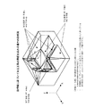
Based on the three-dimensional CAD data 100, the three-dimensional shape
[0053]
The three-dimensional shape
[0054]
2-2. [Calculation of removal volume]
FIG. 7 is an explanatory diagram of a procedure in which the three-dimensional shape
[0055]
The three-dimensional shape
[0056]
As described above, after calculating the volume of the three-dimensional model 91 in FIG. 9A, the maximum length in the X direction, the maximum length in the Y direction, and the maximum length in the Z direction are obtained for the three cutting
[0057]
2-3. [Calculation of surface information]
FIG. 10 is an explanatory diagram of a procedure in which the three-dimensional shape
[0058]
The three-dimensional shape
[0059]
As a result, for the surface perpendicular to the machining axis in the three-dimensional model, that is, the surface that can be machined by the flat end mill, the area for each position in the Z-axis direction, that is, the area estimated to be able to be machined at a time, is obtained. When determining the processing conditions, the processing condition
[0060]
2-4. [Calculation of minimum concave radius]
FIG. 12 is an explanatory diagram of a procedure in which the three-dimensional shape
[0061]
Based on the three-dimensional CAD data 100, the three-dimensional shape
[0062]
Then, as shown in FIG. 13A, the three-dimensional shape
[0063]
Accordingly, when the cutting condition
[0064]
2-5. [Calculation of the radius of the most concave shape]
FIG. 14 is an explanatory diagram of a procedure in which the three-dimensional shape
[0065]
The three-dimensional shape
[0066]
Then, the three-dimensional shape
[0067]
Thus, when the cutting condition
[0068]
2-6. [Calculation of maximum depth]
FIG. 16 is an explanatory diagram in the case where the three-dimensional shape
[0069]
The three-dimensional shape
[0070]
Accordingly, when the cutting condition
[0071]
2-7. [Calculation of cutting range boundary]
FIG. 17 is an explanatory diagram of a case where the three-dimensional shape
[0072]
The three-dimensional shape
[0073]
Then, the faces sharing the edge for each classification are grouped to obtain a processing range, and the edges in each group that are not shared with other faces are obtained as the processing range boundary lines. For example, in FIG. 17, the
[0074]
Thus, when the cutting condition
[0075]
2-8. [Calculation of blank dimensions]
FIG. 18 is an explanatory diagram in the case where the three-dimensional shape
[0076]
The three-dimensional shape
[0077]
3. [Determination of machining conditions based on past machining results]
The
[0078]
The
[0079]
For example, when the search condition is the maximum outer dimension, the X-axis maximum length of the three-dimensional model is compared with the X-axis maximum length of the machining case, and the dimensional difference is obtained as an absolute value. The dimension difference in the axial direction is obtained, and if all in the XYZ axis directions are equal to or less than a value (δ) predetermined by the system, the maximum external dimension is regarded as having a similar shape.
[0080]
When the search condition is the removal volume, the difference between the removal volume (cutting volume) of the three-dimensional model and the past machining case is obtained, and the absolute value is equal to or less than the value (δV) determined in advance by the system. And the removal volume is considered to be similar.
[0081]
When the search condition is plane information, the difference between the area of the three-dimensional model and the plane parallel to the XY plane of the machining case is obtained, and when the absolute value is equal to or smaller than a value (δA) determined in advance by the system, the plane information is obtained. Are considered similar.
[0082]
When the search condition is the most concave shape radius dimension, the difference between the most concave shape radius dimension between the three-dimensional model and the past machining case is obtained, and when the absolute value is equal to or less than the value (δR) determined in advance by the system. The most concave shape radius dimensions are considered to be similar.
[0083]
When the search condition is the minimum concave radius, the difference between the minimum concave radius of the three-dimensional model and the past processed shape is obtained, and the absolute value is equal to or smaller than a value (δMR) determined in advance by the system. Is considered to be similar in minimum concave radius.
[0084]
When the search condition is the maximum depth, the difference between the maximum depth dimension of the three-dimensional model and the past machining case is obtained, and when the absolute value is equal to or less than the value (δD) predetermined by the system, the maximum depth is obtained. The dimensions are considered to be similar.
[0085]
The
[0086]
In addition, the cutting condition
[0087]
4-1. [Adjustment of cutting pitch and Z depth of cut by machining surface roughness]
When there are few machining examples in the
[0088]
At this time, as shown in FIG. 22, when the scallop height is H, the feed pitch is P, and the machining tool radius (here, ball end mill) is R, the theoretical surface roughness is H = R− (R 2 −P 2 / 4) 1/2 The scallop height H, that is, the theoretical surface roughness is determined by giving the finishing tool and the feed pitch under the above cutting conditions.
[0089]
Therefore, the roughness of the machined surface determined under the above-described cutting conditions is the theoretical surface roughness. However, when actual machining is performed, the actual roughness of the machined surface (actual machined surface roughness) differs depending on the type of the workpiece and the feed rate.
[0090]
Therefore, the cutting condition
[0091]
The processing condition threshold database 16a obtains a correspondence relationship between an actual processing surface roughness and a processing condition when the roughness is obtained, based on a cutting experiment, a cutting example, and processing data provided from a processing tool maker. It is something that I remember.
[0092]
First, the cutting condition
[0093]
If the theoretical roughness and the actual machining surface roughness do not match, the cutting condition
[0094]
As a result, it is possible to automatically output the cutting conditions for obtaining the required processing surface roughness even in a new shape having no processing examples.
[0095]
4-2. [Control considering spindle load]
FIG. 24 shows a procedure of monitoring the spindle load at the time of machining in the steps S7 to S9 and controlling to perform appropriate machining.
The automatic NC
[0096]
First, the automatic NC
[0097]
In addition, the automatic NC
[0098]
At this time, the
[0099]
t * f = (6120 * P * n) / (k * v) (Equation 1)
However,
t: pitch (or depth of cut, mm), f: feed speed (mm / min), P: spindle power (kW)
n: machine tool efficiency (≒ 0.8), k: specific cutting resistance (depends on work material)
v: Cutting speed (tool peripheral speed, m / min)
The automatic NC
[0100]
If it is determined that the machining has been completed (S84), the machining
[0101]
Thus, even when the set processing conditions are not appropriate, the feed rate can be controlled in real time to prevent the
[0102]
Further, since the processing result is registered as the processing result, the processing can be performed with an appropriate value from the beginning at the next processing.
[0103]
Further, the value to be monitored and controlled is not limited to the feed speed, but may be a spindle speed, a Z-cut amount, a feed pitch, or the like. Also, instead of controlling these independently, the control items are controlled over all items, such as the control of the spindle speed next to the control of the feed speed, the control of the Z-cut amount, and the control of the feed pitch. , Can also be controlled.
[0104]
5-1. [Determination of tool diameter based on cutting range]
FIGS. 25 to 27 are explanatory diagrams of a case where the tool diameter is obtained based on the cutting range boundary line obtained in the section 2-7.
[0105]
Upon acquiring the cutting range boundary as described above (S101), the cutting condition
[0106]
Then, the cutting condition
[0107]
5-2. [Determination of tool overhang based on cutting depth]
FIG. 28 is an explanatory diagram in the case where the tool protrusion amount is obtained based on the cutting depth obtained in the section 2-6.
[0108]
Upon acquiring the cutting range boundary line as described above (S91), the cutting condition
[0109]
If the tool cannot be used, a tool close to the maximum depth and having a short protrusion or full length is searched from the tool library, and an interference check is similarly performed by combining the designated holder.
[0110]
The cutting condition
[0111]
5-3. [Determination of tool type based on surface information]
FIG. 30 is an explanatory diagram in the case where the type of the working tool is obtained based on the surface information obtained in the section 2-3.
[0112]
The cutting condition
[0113]
6. [Detection of tool life or breakage]
FIG. 31 and FIG. 32 are explanatory diagrams of a procedure for detecting tool life or breakage.
[0114]
The NC data automatically created by the automatic NC
[0115]
The automatic NC
[0116]
When the cutting conditions are controlled in real time, the automatic NC
[0117]
Here, when the change of the cutting condition is a change of the feed rate (A4: YES), a command to reduce the feed rate by a predetermined value at a predetermined rate or the like is issued to the cutting
[0118]
If the change of the cutting condition is a change of the spindle rotation speed (A4 is NO), the cutting
[0119]
When the cutting condition database 16c is changed after the cutting, as shown in FIG. 32, the cutting conditions during the cutting are not changed, the cutting is performed according to the first NC data, and the monitored abnormal wear and destruction is performed. The number of generated ultrasonic waves relating to the phenomenon is temporarily stored in the
[0120]
After the cutting is completed, the
[0121]
If the setting of the cutting condition change is not a change of the feed speed, it is determined whether or not the change is the change of the spindle rotation speed (A14) or the change of the feed pitch (A15). If so, this information is transmitted to the machining
[0122]
If the setting of the cutting condition change is not any of the above changes, the machining
[0123]
As a result, as for the setting of the cutting processing conditions for the next and subsequent times, the processing conditions and the NC data reflecting this change can be output.
[0124]
By performing the above operations, cutting conditions can be automatically controlled so that abnormal wear of the tools does not occur when using the same type of processing tools.
[0125]
In the present embodiment, the physical phenomenon is described as an ultrasonic wave, but the physical phenomenon is not only an ultrasonic wave, but also a sound and vibration felt by the five senses of a human, a change in the shape of a tool, a use time, and even a human such as an ultrasonic wave. Any phenomena that can be detected by a sensor, such as physical phenomena that are not felt by the five senses, may be used.
[0126]
7. [Control to handle multiple tools as a processing tool set]
The cutting is generally performed in a plurality of steps such as roughing, semi-finishing, and finishing. In this case, first, rough cutting is performed roughly with a tool for rough machining, and then the uncut portion is cut with a tool for semi-finishing. At this time, as shown in FIG. 33 (a), if a tool C with an excessive amount of cutting is selected as a tool for semi-finishing processing, cutting will be performed more than necessary, resulting in a rough finish. . For this reason, it is necessary to select a tool B for semi-finishing that is capable of cutting unremoved and capable of cutting to the extent that finishing with the finishing tool A is possible as shown in FIG. There is. When selecting a tool in this way, it is desirable to select a tool in consideration of tools to be used in processes before and after the tool.
[0127]
Therefore, in the present embodiment, as shown in FIGS. 34 and 35, a plurality of tools are handled and selected as a set (FIG. 33C).
[0128]
First, the three-dimensional shape
[0129]
The cutting condition
[0130]
Next, the cutting condition
[0131]
Next, the cutting condition
[0132]
Next, the cutting condition
[0133]
Then, the cutting condition
[0134]
This makes it possible to automatically design a machining process using an appropriate tool.
[0135]
8. [Control to determine tool and machining process from target time]
3, 36, 37, and 38 are explanatory diagrams of control for determining a tool and a machining process from a target time. As shown in the figure, the machining control device of the present invention executes each step of a method for deciding a tool and a machining process from a target time according to the machining control program (including a tool determination program).
[0136]
First, in
[0137]
In
[0138]
In
[0139]
When the machining case is found (S4), the process proceeds to step 5, and the cutting condition
[0140]
FIG. 37 is a diagram showing in detail a procedure for determining a tool and a machining step in
[0141]
As shown in the drawing, the cutting condition
[0142]
In step 501, a minimum tool diameter required for cutting is determined based on information on usable tools stored in a tool library and the three-dimensional CAD data. That is, the minimum concave radius dimension is obtained from the three-dimensional CAD data as described in the above section 2-4, and among the tool diameters stored in the tool library, the closest diameter less than or equal to this dimension is defined as the minimum tool diameter.
[0143]
As the tool library, for example, as shown in Table 1, the tool diameter, feed speed, pitch, Z-cut amount, and cut amount per unit time of usable tools are stored.
[0144]
[Table 1]
[0145]
In step 503, a time T1 when the entire tool surface is cut with the tool TL1 having the minimum tool diameter is calculated. That is, the cutting time T1 is obtained by dividing the volume of the stay surface by the cutting amount of the tool TL1 per unit time.
[0146]
In step 504, the target time T is compared with the cutting time T1, and if T <T1, the process proceeds to step 505, and if T ≧ T1, the process proceeds to step 507.
[0147]
In step 505, tools are added in order from the tool having the minimum tool diameter, and a cutting time Tn when cutting is performed with up to n tools is calculated. This additional tool is extracted for every predetermined number of tools that can be used, the tools having a larger diameter than the tool for which the cutting time has already been calculated. For example, if the minimum tool diameter is φ1 and extraction is performed for each one, then a tool with a tool diameter φ2 is added as TL2. Further, the predetermined number may be stored in the cutting example database in association with the target information, and may be a value retrieved according to the target information. For example, if the product type is a mold, extraction is performed for each one, and if the product type is a personal computer housing, extraction is performed for every two.
[0148]
In step 505, the calculation of the cutting time Tn is performed by cutting the Z-cut amount with a tool up to TLn-1 when the n-th tool is TLn, and performing the remaining cutting with the tool TLn. The calculated time is calculated as the time Tn. That is, in Step 503, as shown by the hatched portion in FIG. 36B, the machining time when the entire stair surface is cut with the tool TL1 is obtained, whereas in Step 505, the second tool TL2 is obtained. In the case where is added, as shown in FIG. 36 (c), cutting is performed by the Z-cut amount with the tool TL1 (shaded portion), and the time T2 when the remaining vertical line portion is cut with TL2 is obtained. When TL3 is further added, time T3 is obtained as shown in FIG.
[0149]
For example, when processing a blank (work) of 100 × 80 × 50 (mm) into a final shape as shown in FIG. 38A, the minimum tool diameter is set to φ1 and registered in the tool library shown in Table 1. When the machining is performed by adding seven tools one by one and performing the machining with seven tools, as shown in FIG. 38 (b), the cutting is performed by the Z-cut amount with the tools TL1 to TL6, respectively. The remaining cutting is performed with the tool TL7.
[0150]
Table 2 shows the volume to be cut by each of the tools TL1 to TL8 when machining is performed with the n tools.
[0151]
[Table 2]
[0152]
[Table 3]
[0153]
In step 507, a tool to be used is determined from the n tools when the cutting time Tn is shorter than the target time. That is, if the cutting time T1 is equal to or less than the target time T, only the tool TL1 is used. If the cutting time Tn is equal to or less than the target time Tn = T5, the tool to be used is determined from TL1 to TL5. For example, if the target time is 330 seconds in the example of Table 3, the tool to be used is determined from TL1 to TL7.
[0154]
The method of determining a tool to be used from among the plurality of tools is arbitrary, and all tools may be used, or a predetermined number may be selected. For example, when three tools are selected from n tools (in this case, n is three or more), a tool having the smallest diameter, a tool having the largest diameter, and one tool having an intermediate diameter are selected. Similarly, when four tools are selected from the n tools, a tool having the smallest diameter, a tool having the largest diameter, and two tools having a middle diameter are selected.
[0155]
In
[0156]
Then, the processing after
[0157]
As described above, tools are sequentially added from the tool TL1 having the smallest tool diameter, the tool TLn when the target time is achieved is determined, and the tool is determined to use TL1 to TLn. Even if there is no similar processing example, a target time can be determined from general information such as a product type and a blank material, and a tool can be easily determined.
[0158]
Also, when a human tries to determine a tool in the order of larger diameter, the tool can be used in order from the largest tool in the tool library, regardless of the shape of the target object. The tool with the minimum tool diameter can be uniquely obtained from the three-dimensional CAD data of the target object, and the tool with the smallest tool diameter must be determined in ascending order of the diameter. If this is the case, it is possible to efficiently determine the tools and, consequently, the processing steps.
[0159]
9. [Control to determine tool and machining process from reduction time]
FIGS. 3 and 39 are explanatory diagrams of control for determining a tool and a machining process from the reduction time. As shown in the figure, the machining control device of the present invention executes each step of a method for deciding a tool and a machining process from the reduction time according to the machining control program (including the tool determination program).
[0160]
First, in
[0161]
In
[0162]
In
[0163]
When the machining case is found (S4), the process proceeds to step 5, and the cutting condition
[0164]
FIG. 39 is a diagram showing in detail a procedure for determining a tool and a machining process in
[0165]
As shown in the figure, the cutting condition
[0166]
In step 511, the minimum tool diameter required for cutting is determined based on information on usable tools stored in the tool library and the three-dimensional CAD data. That is, the minimum concave radius dimension is obtained from the three-dimensional CAD data as described in the above section 2-4, and among the tool diameters stored in the tool library, the closest diameter less than or equal to this dimension is defined as the minimum tool diameter.
[0167]
As the tool library, for example, as shown in Table 1, the tool diameter, feed speed, pitch, Z-cut amount, and cut amount per unit time of usable tools are stored.
[0168]
In step 512, the cut-off time is determined based on the processing case (reference value) found by the
[0169]
At step 513, the time T1 when the entire tool surface is cut with the tool TL1 having the minimum tool diameter is calculated. That is, the cutting time T1 is obtained by dividing the volume of the stay surface by the cutting amount of the tool TL1 per unit time.
[0170]
In step 514, tools are added in order from the tool having the minimum tool diameter, and a cutting time Tn when cutting is performed with the n-th tool is calculated. This additional tool is extracted for every predetermined number of tools that can be used, the tools having a larger diameter than the tool for which the cutting time has already been calculated.
[0171]
In this step 514, the calculation of the cutting time Tn is performed by cutting the Z-cut amount with a tool up to TLn-1 when the n-th tool is TLn, and performing the remaining cutting with the tool TLn. The time is calculated as the time Tn.
[0172]
Table 2 shows the volume to be cut by each of the tools TL1 to TL8 when machining is performed with the n tools.
[0173]
That is, the cutting time Tn in the case of performing the cutting process in each number is the sum of the time in which the tool TL1 to Tn-1 performs the cutting for the Z depth of cut and the time in which the tool TLn performs the remaining cutting. .
[0174]
In
[0175]
At this time, Table 4 shows the reduction time (time difference α and reduction rate β) when cutting is performed with each number of tools.
[0176]
[Table 4]
[0177]
The method of determining a tool to be used from among the plurality of tools is arbitrary, and all tools may be used, or a predetermined number may be selected. For example, when three tools are selected from n tools (in this case, n is three or more), a tool having the smallest diameter, a tool having the largest diameter, and one tool having an intermediate diameter are selected. Similarly, when four tools are selected from the n tools, a tool having the smallest diameter, a tool having the largest diameter, and two tools having a middle diameter are selected.
[0178]
In step 517, a machining step is determined from the selected tools in the descending order of the tool diameter. For example, if the retrieved tool set is a ball end mill having a diameter of 10 mm, a diameter of 6 mm, a diameter of 3 mm, and a diameter of 1 mm, the first processing step is performed for a diameter of 10 mm, and the second processing step is performed for a diameter of 6 mm. The third machining step is assigned to a diameter of 3 mm, the fourth machining step is assigned to a diameter of 1 mm, and the machining step is assigned to the machining tool so that the diameter of the machining tool is changed from a large diameter to a small diameter.
[0179]
Then, the processing after
[0180]
As described above, tools are sequentially added from the tool TL1 having the smallest tool diameter, the tool TLn when the target time is achieved is determined, and the tool is determined to use TL1 to TLn. Even if there is no similar processing example, a target time can be determined from general information such as a product type and a blank material, and a tool can be easily determined.
[0181]
Also, when a human tries to determine a tool in the order of larger diameter, the tool can be used in order from the largest tool in the tool library, regardless of the shape of the target object. The tool with the minimum tool diameter can be uniquely obtained from the three-dimensional CAD data of the target object, and the tool with the smallest tool diameter must be determined in ascending order of the diameter. If this is the case, it is possible to efficiently determine the tools and, consequently, the processing steps.
[0182]
§3. Effects of the embodiment
As described above, according to the present embodiment, the fact that a person has recognized a machining shape and has determined a cutting process, a tool to be used, cutting conditions, and the like based on experience has been used. By searching and deciding the processing conditions based on this, and systemizing the process of deciding the processing conditions that people were thinking in mind, even those who have never experienced cutting work safely and with high quality, and with others, Cutting with reduced quality variation due to know-how and experience is possible.
[0183]
Also, by acquiring numerical data from actual machining phenomena and storing it in a database as machining examples, it can be extracted according to the characteristics of the machining shape, so that know-how that could only be left in the memory of experienced people until now It is left as a database and can be reused.
[0184]
Further, even for an object having no cutting experience, an appropriate tool and process can be easily determined based on general information (default value) such as a product type and a blank material. In addition, even if the target object has no cutting processing experience, it can be properly processed, and variations in processing quality due to differences in operator experience can be suppressed. Further, by searching from the minimum tool diameter, tools and processes can be efficiently determined.
[0185]
<Other embodiments>
It should be noted that the present invention is not limited to the illustrated examples described above, and it is needless to say that various changes can be made without departing from the spirit of the present invention.
[0186]
For example, the same effects as those of the above-described embodiment can be obtained even with the configuration described below.
[0187]
(Appendix 1)
A shape feature extraction unit that obtains shape information about a feature of a three-dimensional shape from design data of an object;
A machining case storage unit that stores machining conditions of machining performed in the past as machining cases;
A case search unit that searches for a machining case from the machining case storage unit based on the shape information;
A processing condition setting unit that determines a processing condition based on the processing case searched by the case search unit;
A control unit that controls the processing machine based on the processing conditions,
Processing control device equipped with
[0188]
(Appendix 2)
A criterion storage unit storing information serving as a criterion for processing conditions is provided,
2. The processing control device according to
[0189]
(Appendix 3)
A pre-processing input unit that receives input of information on the object,
2. The processing control device according to
[0190]
(Appendix 4)
A monitoring unit that acquires information on a processing machine when the control unit performs control based on the processing conditions,
A processing case registration unit that stores information of the processing machine acquired by the monitoring unit in the processing case storage unit as a processing case in association with the shape information;
The processing control device according to
[0191]
(Appendix 5)
A monitoring unit that acquires information on a processing machine when the control unit performs control based on the processing conditions,
A processing case registration unit that stores information of the processing machine acquired by the monitoring unit in the processing case storage unit as a processing case in association with the shape information;
A post-processing input unit for receiving input of information on the quality of the processing,
The processing control device according to
[0192]
(Appendix 6)
An X value when the shape feature extraction unit divides the surface of the object indicated in the design data into polygons, and expresses coordinates of vertices of the polygon by values in the X, Y, and Z directions; Y values, obtained as Z values, the minimum X value and the maximum X value, the minimum Y value and the maximum Y value, the minimum Z value and the maximum Z value among all the vertices,
Subtract the minimum X value from the maximum X value to find the maximum length in the X-axis direction,
Subtract the minimum Y value from the maximum Y value to find the maximum length in the Y-axis direction,
2. The processing control device according to
[0193]
(Appendix 7)
The shape feature extraction unit projects all the polygons on an XY plane where the lowermost part of the object is located, and connects respective vertices of each polygon with the corresponding vertices of the projected polygon on the XY plane. The volume of the polygonal prism created by the above is obtained, and this operation is repeated for all the polygons to obtain the volume of the object. The maximum length in the X-axis direction, the maximum length in the Y-axis direction, and the maximum length in the Z-
[0194]
(Appendix 8)
The processing control device according to
[0195]
(Appendix 9)
2. The processing control device according to
[0196]
(Appendix 10)
The shape feature extraction unit extracts a concave portion of the object indicated in the design data, classifies the concave portion for each radial dimension, obtains an area of the concave portion for each radial dimension, 2. The processing control device according to
[0197]
(Appendix 11)
When the shape feature extraction unit divides the surface of the object shown in the design data into polygons and expresses the coordinates of the vertices of the polygon by values in the X, Y, and Z directions,
[0198]
(Appendix 12)
The shape feature extraction unit divides the surface of the object shown in the design data into polygons, determines whether the normal of the polygon is parallel to the processing axis, and a polygon that is parallel, Classify into non-parallel polygons, group polygons that share edges for each classification as a processing range, and find edges not shared with other polygons in each group as
[0199]
(Appendix 13)
The shape feature extraction unit adds a machining allowance of a machining case searched by the case search unit to the maximum length in the X-axis direction, the maximum length in the Y-axis direction, and the maximum length in the Z-axis direction to obtain a blank dimension. 7. The processing control device according to 6.
[0200]
(Appendix 14)
A monitoring unit that acquires information on a processing machine when the control unit performs control based on the processing conditions,
A post-processing input unit that receives input of information on the quality of the processing result when performing the control,
A processing case registration unit that stores information on the processing machine and the quality of the processing result obtained by the monitoring unit in a processing case storage unit as a processing case in association with the shape information;
The processing control device according to
[0201]
(Appendix 15)
The case search unit searches a processing case database using the shape information obtained from the shape feature extraction unit as a search key, and compares the shape information obtained from the shape feature extraction unit with shape information falling within a predetermined range. The processing control device according to
[0202]
(Appendix 16)
The processing machine is a cutting machine, the monitoring unit measures the spindle load state of the processing machine,
The processing control device according to
[0203]
(Appendix 17)
The processing machine is a cutting machine, the monitoring unit measures the spindle load state of the processing machine,
The processing control device according to
[0204]
(Appendix 18)
When a plurality of tools are used in order, the machining condition setting unit compares the remaining amount of the first used tool with the allowable range of the next used tool, and determines the remaining amount of the first used tool to be the next. 2. The machining control device according to
[0205]
(Appendix 19)
When using a plurality of tools in order, the machining condition setting unit compares the remaining amount of cutting of the tool used first and the allowable range of the tool used next,
If the remaining cutting amount of the tool used first exceeds the upper limit of the allowable range of the tool used next, add the tool used between the tool used first and the tool used next,
If the remaining amount of the first tool used is below the lower limit of the allowable range of the next tool, compare the remaining amount of the first tool with the allowable range of the next tool. The processing control device according to
[0206]
(Appendix 20)
Acquiring shape information related to the feature of the three-dimensional shape from the design data of the object;
Searching for a machining case based on the shape information from a machining case storage unit that stores machining conditions of machining performed in the past as a machining case;
Determining a processing condition based on the processing case searched by the case search unit;
Controlling the processing machine based on the processing conditions;
Control program that causes a computer to execute
[0207]
(Appendix 21)
A processing control system including a processing machine and a processing control device that controls the processing machine,
The processing control device,
A shape feature extraction unit that obtains shape information about a feature of a three-dimensional shape from design data of an object;
A machining case storage unit that stores machining conditions of machining performed in the past as machining cases;
A case search unit that searches for a machining case from the machining case storage unit based on the shape information;
A processing condition setting unit that determines a processing condition based on the processing case searched by the case search unit;
A control unit that controls the processing machine based on the processing conditions;
A processing control system comprising:
[0208]
(Appendix 22)
A criterion storage unit having a tool library storing information of usable tools,
The processing condition setting unit determines a minimum tool diameter required for cutting based on the design data and information on usable tools, and based on the processing case searched by the case search unit, a target time T for cutting. Is determined, a tool is added in order from the tool having the minimum tool diameter, a time Tn when cutting is performed with the nth tool is calculated, and the time Tn becomes shorter than the target time T until the time Tn becomes shorter than the target time T. The processing control apparatus according to
[0209]
(Appendix 23)
A criterion storage unit having a tool library storing information of usable tools,
The machining condition setting unit determines a minimum tool diameter required for cutting based on the design data and information on usable tools, and adds a tool in order from the tool having the minimum tool diameter to the n-th tool. Calculate the time Tn in the case of performing the cutting in the above, if the time Tn is shorter than the time Tn-1 in the case of performing the cutting with the n-1 th tool by a predetermined value or more, the tool is The process according to
[0210]
(Appendix 24)
A shape feature extraction unit for acquiring shape information on three-dimensional shape features from design data of an object; a judgment criterion storage unit having a tool library storing information of usable tools; A processing case storage unit that stores a processing case as a processing case, a case search unit that searches for a processing case from the processing case storage unit based on the shape information, and a processing condition based on the processing case searched by the case search unit. A processing condition setting unit to determine, a control unit that controls the processing machine based on the processing conditions, a tool determination method by a processing control device including a,
The processing condition setting unit,
Determining the minimum tool diameter required for cutting based on the design data and information on available tools,
Determining a target time T for cutting based on the processing case searched by the case searching unit;
A step of adding a tool in order from the tool having the minimum tool diameter, and calculating a time Tn when cutting is performed with up to n tools;
Comparing the time Tn with the target time T and repeating the step of calculating the time Tn by adding the tool until the time Tn becomes shorter than the target time T;
A tool determining method for executing a step of determining a tool to be used from n tools when the time Tn is shorter than a target time.
[0211]
(Appendix 25)
A shape feature extraction unit for acquiring shape information on three-dimensional shape features from design data of an object; a judgment criterion storage unit having a tool library storing information of usable tools; A processing case storage unit that stores a processing case as a processing case, a case search unit that searches for a processing case from the processing case storage unit based on the shape information, and a processing condition based on the processing case searched by the case search unit. A processing condition setting unit to determine, a control unit that controls the processing machine based on the processing conditions, a tool determination method by a processing control device including a,
The processing condition setting unit,
Determining the minimum tool diameter required for cutting based on the design data and information on available tools,
A step of adding a tool in order from the tool having the minimum tool diameter and calculating a time Tn when cutting is performed with the nth tool;
The time Tn-1 when cutting is performed with the n-1th tool is compared with the time Tn. If the time Tn is shorter than the time Tn-1 by a predetermined value or more, the tool is added. Repeating the process of calculating the time Tn;
A tool determining method for executing a step of determining a tool to be used from n-1 tools when the time Tn is not shorter than the time Tn-1 by a predetermined value or more.
[0212]
(Supplementary Note 26)
A shape feature extraction unit for acquiring shape information on three-dimensional shape features from design data of an object; a judgment criterion storage unit having a tool library storing information of usable tools; A processing case storage unit that stores a processing case as a processing case, a case search unit that searches for a processing case from the processing case storage unit based on the shape information, and a processing condition based on the processing case searched by the case search unit. A processing condition setting unit to be determined, and a control unit that controls a processing machine based on the processing condition,
Determining the minimum tool diameter required for cutting based on the design data and information on available tools,
Determining a target time T for cutting based on the processing case searched by the case searching unit;
A step of adding a tool in order from the tool having the minimum tool diameter, and calculating a time Tn when cutting is performed with up to n tools;
Comparing the time Tn with the target time T and repeating the step of calculating the time Tn by adding the tool until the time Tn becomes shorter than the target time T;
A tool determination program for executing a step of determining a tool to be used from n tools when the time Tn becomes shorter than the target time.
[0213]
In the present invention, the above components can be combined as much as possible.
[0214]
《Computer readable recording medium》
The present invention may be a recording medium in which the program is recorded on a computer-readable recording medium. Then, by causing the computer to read and execute the program on the recording medium, the function can be provided.
[0215]
Here, the computer-readable recording medium refers to a recording medium in which information such as data and programs is stored by electrical, magnetic, optical, mechanical, or chemical action and can be read by a computer. Examples of such a recording medium that can be removed from a computer include a flexible disk, a magneto-optical disk, a CD-ROM, a CD-R / W, a DVD, a DAT, an 8 mm tape, a memory card, and the like.
[0216]
Further, as a recording medium fixed to the computer, there is a hard disk, a ROM (Read Only Memory) or the like.
[0219]
【The invention's effect】
As described above, the present invention makes it possible to perform processing under appropriate processing conditions by searching for processing examples according to the features of the shape to be processed and setting processing conditions based on the processing examples. .
[Brief description of the drawings]
FIG. 1 is a schematic diagram of a machining control system according to the present invention.
FIG. 2 is a schematic configuration diagram of a processing control device.
FIG. 3 is an explanatory diagram of a machining control procedure.
FIG. 4 is a flowchart for calculating a maximum external dimension.
FIG. 5 is an explanatory diagram of calculation of a maximum external dimension.
FIG. 6 is an explanatory diagram of calculation of a maximum external dimension.
FIG. 7 is a flowchart of a removal volume calculation.
FIG. 8 is an explanatory diagram of removal volume calculation.
FIG. 9 is an explanatory diagram of removal volume calculation.
FIG. 10 is a flowchart of surface information acquisition.
FIG. 11 is an explanatory diagram of a surface information acquisition procedure.
FIG. 12 is a flowchart of obtaining a minimum concave shape radius;
FIG. 13 is an explanatory diagram of acquiring a minimum concave shape radius.
FIG. 14 is a flowchart for obtaining the most concave shape radius.
FIG. 15 is an explanatory diagram of obtaining the most concave shape radius.
FIG. 16 is an explanatory diagram of a maximum depth calculation.
FIG. 17 is an explanatory diagram of processing boundary acquisition.
FIG. 18 is a flowchart of blank dimension calculation.
FIG. 19 is an explanatory diagram of blank dimension calculation.
FIG. 20 is an explanatory diagram of a cutting example database.
FIG. 21 is an explanatory diagram of processing condition determination.
FIG. 22 is an explanatory diagram of processing control based on a processing surface roughness.
FIG. 23 is an explanatory diagram of processing control based on a processing surface roughness;
FIG. 24 is a flowchart of machining control based on a spindle load.
FIG. 25 is an explanatory diagram when a tool diameter is obtained based on a cutting range boundary line.
FIG. 26 is a flowchart for obtaining a tool diameter based on a cutting range boundary line.
FIG. 27 is a flowchart for obtaining a tool diameter based on a cutting range boundary line.
FIG. 28 is a flowchart for obtaining a tool protrusion amount based on a cutting depth.
FIG. 29 is an explanatory diagram in a case where a tool protrusion amount is obtained based on a cutting depth.
FIG. 30 is an explanatory diagram when a type of a machining tool is obtained based on surface information.
FIG. 31 is a flowchart of control for detecting tool life or breakage.
FIG. 32 is a flowchart of control for detecting tool life or breakage.
FIG. 33 is an explanatory diagram when a plurality of tools are selected as a set.
FIG. 34 is a flowchart of control for selecting a plurality of tools as a set.
FIG. 35 is a flowchart of control for selecting a plurality of tools as a set.
FIG. 36 is an explanatory diagram of control for determining a tool and a machining step.
FIG. 37 is a flowchart of control for determining a tool and a process from a target time.
FIG. 38 is an explanatory diagram of control for determining a tool and a machining step.
FIG. 39 is a flowchart of control for determining a tool and a process from the reduction time.
[Explanation of symbols]
1 Processing control device
2 Processing machine
10 Monitoring Department
11 Input part before processing
12 3D shape feature extraction unit
13 Case Search Department
14 Cutting condition automatic setting section
15 Cutting example database
16 Judgment criteria database
16a Processing condition threshold database
16b Tool library
16c Cutting condition database
17 Machining case registration department
18 Input part after machining
19 Data creation unit
21 Cutting part
22 Processing machine control unit
22a Sensor unit
22b Cutting control unit
22c Magazine Management Department
23 Magazine
31 body
32 arithmetic processing unit
33 Storage
33 storage unit
34 Input / output unit
100 3D data
Claims (10)
過去に行った加工の加工条件を加工事例として記憶する加工事例記憶部と、
前記形状情報に基づいて前記加工事例記憶部から加工事例を索出する事例検索部と、
前記事例検索部で検索した加工事例に基づいて加工条件を決定する加工条件設定部と、
前記加工条件に基づいて加工機の制御を行う制御部と、
を備えた加工制御装置。A shape feature extraction unit that obtains shape information about a feature of a three-dimensional shape from design data of an object;
A machining case storage unit that stores machining conditions of machining performed in the past as machining cases;
A case search unit that searches for a machining case from the machining case storage unit based on the shape information;
A processing condition setting unit that determines a processing condition based on the processing case searched by the case search unit;
A control unit that controls the processing machine based on the processing conditions,
Processing control device equipped with
前記加工条件設定部が、前記判断基準記憶部の情報と前記事例検索部で検索した加工事例とに基づいて加工条件を決定する請求項1に記載の加工制御装置。A criterion storage unit storing information serving as a criterion for processing conditions is provided,
The processing control device according to claim 1, wherein the processing condition setting unit determines a processing condition based on information in the determination criterion storage unit and a processing case searched by the case search unit.
前記モニタリング部で取得した前記加工機の情報を前記形状情報と対応づけて加工事例として前記加工事例記憶部に記憶させる加工事例登録部と、
を備える請求項1に記載の加工制御装置。A monitoring unit that acquires information on a processing machine when the control unit performs control based on the processing conditions,
A processing case registration unit that stores information of the processing machine acquired by the monitoring unit in the processing case storage unit as a processing case in association with the shape information;
The processing control device according to claim 1, further comprising:
前記モニタリング部で取得した前記加工機の情報を前記形状情報と対応づけて加工事例として前記加工事例記憶部に記憶させる加工事例登録部と、
前記加工の良否に関する情報の入力を受け付ける加工後入力部と、
を備え、前記加工後入力部で受け付けた情報に応じて、前記加工事例登録部が前記加工事例を前記加工事例記憶部に記憶させる請求項1に記載の加工制御装置。A monitoring unit that acquires information on a processing machine when the control unit performs control based on the processing conditions,
A processing case registration unit that stores information of the processing machine acquired by the monitoring unit in the processing case storage unit as a processing case in association with the shape information;
A post-processing input unit for receiving input of information on the quality of the processing,
The processing control device according to claim 1, further comprising: the processing case registration unit causing the processing case storage unit to store the processing case according to the information received by the post-processing input unit.
最大X値から最少X値を減じてX軸方向最大長さを求め、
最大Y値から最少Y値を減じてY軸方向最大長さを求め、
最大Z値から最少Z値を減じてZ軸方向最大長さを求める請求項1に記載の加工制御装置。An X value when the shape feature extraction unit divides the surface of the object indicated in the design data into polygons, and expresses coordinates of vertices of the polygon by values in the X, Y, and Z directions; Y values, obtained as Z values, the minimum X value and the maximum X value, the minimum Y value and the maximum Y value, the minimum Z value and the maximum Z value among all the vertices,
Subtract the minimum X value from the maximum X value to find the maximum length in the X-axis direction,
Subtract the minimum Y value from the maximum Y value to find the maximum length in the Y-axis direction,
The processing control device according to claim 1, wherein the minimum Z value is subtracted from the maximum Z value to determine the maximum length in the Z-axis direction.
過去に行った加工の加工条件を加工事例として記憶する加工事例記憶部から前記形状情報に基づいて加工事例を索出するステップと、
前記事例検索部で検索した加工事例に基づいて加工条件を決定するステップと、
前記加工条件に基づいて加工機の制御を行うステップと、
をコンピュータに実行させる加工制御プログラム。Acquiring shape information related to the feature of the three-dimensional shape from the design data of the object;
Searching for a machining case based on the shape information from a machining case storage unit that stores machining conditions of machining performed in the past as a machining case;
Determining a processing condition based on the processing case searched by the case search unit;
Controlling the processing machine based on the processing conditions;
Control program that causes a computer to execute
前記加工制御装置が、
目的物の設計データから3次元形状の特徴に関する形状情報を取得する形状特徴抽出部と、
過去に行った加工の加工条件を加工事例として記憶する加工事例記憶部と、
前記形状情報に基づいて前記加工事例記憶部から加工事例を索出する事例検索部と、
前記事例検索部で検索した加工事例に基づいて加工条件を決定する加工条件設定部と、
前記加工条件に基づいて前記加工機の制御を行う制御部と、
を備えることを特徴とする加工制御システム。A processing control system including a processing machine and a processing control device that controls the processing machine,
The processing control device,
A shape feature extraction unit that obtains shape information about a feature of a three-dimensional shape from design data of an object;
A machining case storage unit that stores machining conditions of machining performed in the past as machining cases;
A case search unit that searches for a machining case from the machining case storage unit based on the shape information;
A processing condition setting unit that determines a processing condition based on the processing case searched by the case search unit;
A control unit that controls the processing machine based on the processing conditions;
A processing control system comprising:
前記加工条件設定部が、前記設計データと使用可能な工具の情報に基づいて切削加工に必要な最小工具径を決定し、前記事例検索部で検索した加工事例に基づいて切削加工の目標時間Tを決定し、前記最小工具径の工具から順に工具を追加し、n本目までの工具で切削加工を行った場合の時間Tnを算出し、該時間Tnが目標時間Tより短くなるまで、前記工具を追加して時間Tnを算出する処理を繰り返し、該時間Tnが目標時間よりも短くなった時点でのn本の工具から使用工具を決定する請求項1に記載の加工制御装置。A criterion storage unit having a tool library storing information of usable tools,
The processing condition setting unit determines a minimum tool diameter required for cutting based on the design data and information on usable tools, and based on the processing case searched by the case search unit, a target time T for cutting. Is determined, a tool is added in order from the tool having the minimum tool diameter, a time Tn when cutting is performed with the nth tool is calculated, and the time Tn becomes shorter than the target time T until the time Tn becomes shorter than the target time T. The processing control device according to claim 1, wherein the processing for calculating the time Tn is repeated by adding the following, and the tool to be used is determined from the n tools when the time Tn becomes shorter than the target time.
前記加工条件設定部が、
前記設計データと使用可能な工具の情報に基づいて切削加工に必要な最小工具径を決定するステップと、
前記事例検索部で検索した加工事例に基づいて切削加工の目標時間Tを決定するステップと、
前記最小工具径の工具から順に工具を追加し、n本目までの工具で切削加工を行った場合の時間Tnを算出するステップと、
該時間Tnと目標時間Tとを比較し、該時間Tnが目標時間Tより短くなるまで、前記工具を追加して時間Tnを算出するステップを繰り返すステップと、
該時間Tnが目標時間よりも短くなった時点でのn本の工具から使用工具を決定するステップを実行する工具決定方法。A shape feature extraction unit for acquiring shape information on three-dimensional shape features from design data of an object; a judgment criterion storage unit having a tool library storing information of usable tools; A processing case storage unit that stores a processing case as a processing case, a case search unit that searches for a processing case from the processing case storage unit based on the shape information, and a processing condition based on the processing case searched by the case search unit. A processing condition setting unit to determine, a control unit that controls the processing machine based on the processing conditions, a tool determination method by a processing control device including a,
The processing condition setting unit,
Determining the minimum tool diameter required for cutting based on the design data and information on available tools,
Determining a target time T for cutting based on the processing case searched by the case searching unit;
A step of adding a tool in order from the tool having the minimum tool diameter, and calculating a time Tn when cutting is performed with up to n tools;
Comparing the time Tn with the target time T and repeating the step of calculating the time Tn by adding the tool until the time Tn becomes shorter than the target time T;
A tool determining method for executing a step of determining a tool to be used from n tools when the time Tn is shorter than a target time.
前記加工条件設定部が、
前記設計データと使用可能な工具の情報に基づいて切削加工に必要な最小工具径を決定するステップと、
該最小工具径の工具から順に工具を追加し、n本目までの工具で切削加工を行った場合の時間Tnを算出するステップと、
n−1本目までの工具で切削加工を行った場合の時間Tn−1と前記時間Tnを比較し、時間Tn−1よりも時間Tnが所定値以上短くなった場合、前記工具を追加して時間Tnを算出する処理を繰り返すステップと、
該時間Tn−1よりも時間Tnが所定値以上短くならなかった時点でのn−1本の工具から使用工具を決定するステップを実行する工具決定方法。A shape feature extraction unit for acquiring shape information on three-dimensional shape features from design data of an object; a judgment criterion storage unit having a tool library storing information of usable tools; A processing case storage unit that stores a processing case as a processing case, a case search unit that searches for a processing case from the processing case storage unit based on the shape information, and a processing condition based on the processing case searched by the case search unit. A processing condition setting unit to determine, a control unit that controls the processing machine based on the processing conditions, a tool determination method by a processing control device including a,
The processing condition setting unit,
Determining the minimum tool diameter required for cutting based on the design data and information on available tools,
A step of adding a tool in order from the tool having the minimum tool diameter and calculating a time Tn when cutting is performed with the nth tool;
The time Tn-1 when cutting is performed with the n-1th tool is compared with the time Tn. If the time Tn is shorter than the time Tn-1 by a predetermined value or more, the tool is added. Repeating the process of calculating the time Tn;
A tool determining method for executing a step of determining a tool to be used from n-1 tools when the time Tn is not shorter than the time Tn-1 by a predetermined value or more.
Priority Applications (3)
| Application Number | Priority Date | Filing Date | Title |
|---|---|---|---|
| JP2003202592A JP2004284002A (en) | 2003-01-31 | 2003-07-28 | Working control device |
| EP04001039A EP1443374A3 (en) | 2003-01-31 | 2004-01-20 | Working control device |
| US10/766,043 US7412296B2 (en) | 2003-01-31 | 2004-01-29 | Working control device |
Applications Claiming Priority (2)
| Application Number | Priority Date | Filing Date | Title |
|---|---|---|---|
| JP2003024866 | 2003-01-31 | ||
| JP2003202592A JP2004284002A (en) | 2003-01-31 | 2003-07-28 | Working control device |
Related Child Applications (2)
| Application Number | Title | Priority Date | Filing Date |
|---|---|---|---|
| JP2008060304A Division JP2008183706A (en) | 2003-01-31 | 2008-03-10 | Working control device, tool determining method and tool determining program |
| JP2008060305A Division JP2008155371A (en) | 2003-01-31 | 2008-03-10 | Tool determining method, working control device and tool determining program |
Publications (1)
| Publication Number | Publication Date |
|---|---|
| JP2004284002A true JP2004284002A (en) | 2004-10-14 |
Family
ID=32658613
Family Applications (1)
| Application Number | Title | Priority Date | Filing Date |
|---|---|---|---|
| JP2003202592A Pending JP2004284002A (en) | 2003-01-31 | 2003-07-28 | Working control device |
Country Status (3)
| Country | Link |
|---|---|
| US (1) | US7412296B2 (en) |
| EP (1) | EP1443374A3 (en) |
| JP (1) | JP2004284002A (en) |
Cited By (16)
| Publication number | Priority date | Publication date | Assignee | Title |
|---|---|---|---|---|
| JP2005309673A (en) * | 2004-04-20 | 2005-11-04 | Toyoda Mach Works Ltd | Nc machine tool and compensation working method |
| JP2007108916A (en) * | 2005-10-12 | 2007-04-26 | Fanuc Ltd | Off-line teaching device for robot |
| JP2008015683A (en) * | 2006-07-04 | 2008-01-24 | Fanuc Ltd | Apparatus for producing robot program, program, storage medium, and method |
| JP2016137557A (en) * | 2015-01-29 | 2016-08-04 | ファナック株式会社 | Machine tool having function to automatically change cutting condition |
| JP2018094693A (en) * | 2016-12-15 | 2018-06-21 | 国立大学法人神戸大学 | Processing support system |
| CN109116809A (en) * | 2017-06-23 | 2019-01-01 | 发那科株式会社 | Processing technology management system and processing technology management method |
| DE102018218201A1 (en) | 2017-10-30 | 2019-05-23 | Fanuc Corporation | NUMERICAL CONTROL DEVICE, CNC TOOL MACHINE, NUMERICAL CONTROL PROCEDURE AND NUMERICAL CONTROL PROGRAM |
| DE102018218202A1 (en) | 2017-10-30 | 2019-05-23 | Fanuc Corporation | POST PROCESSOR DEVICE, MACHINE PROGRAM GENERATION PROCESS, CNC PROCESSING SYSTEM AND PROGRAM FOR MACHINE PROGRAM GENERATION |
| JP2020024676A (en) * | 2018-06-14 | 2020-02-13 | サンドビック マシニング ソリューションズ アクティエボラーグ | Machine work based on principles selected from database |
| WO2020090058A1 (en) | 2018-10-31 | 2020-05-07 | 株式会社牧野フライス製作所 | Processing support system |
| KR20200065933A (en) * | 2018-11-30 | 2020-06-09 | (주)승광 | Measurement and Management System for Mold Manufacture Machine |
| JP2021002135A (en) * | 2019-06-20 | 2021-01-07 | ファナック株式会社 | Machining command improvement system and machining command improvement method |
| JP6833150B1 (en) * | 2020-06-30 | 2021-02-24 | 三菱電機株式会社 | Machining program search device and machining program search method |
| JP2021074816A (en) * | 2019-11-07 | 2021-05-20 | キヤノン株式会社 | Tool condition determination device, learning device and method |
| JP2021120841A (en) * | 2020-01-31 | 2021-08-19 | 株式会社小松製作所 | Machine tool system, management method, and management program |
| WO2022186140A1 (en) * | 2021-03-02 | 2022-09-09 | ファナック株式会社 | Numerical control device and computer-readable storage medium |
Families Citing this family (14)
| Publication number | Priority date | Publication date | Assignee | Title |
|---|---|---|---|---|
| US7890406B2 (en) * | 2004-05-13 | 2011-02-15 | Markov Processes International | System and method for visualization of results of multi-criteria financial optimizations |
| JP4058038B2 (en) * | 2004-12-22 | 2008-03-05 | 株式会社日立製作所 | Load monitoring device and load monitoring method |
| US8231620B2 (en) * | 2009-02-10 | 2012-07-31 | Tyco Healthcare Group Lp | Extension cutting blade |
| JP5334701B2 (en) * | 2009-06-22 | 2013-11-06 | 株式会社ジェイテクト | Optimal process determination device and optimal process determination method |
| JP5441627B2 (en) * | 2009-06-22 | 2014-03-12 | 株式会社ジェイテクト | Optimal process determination device and optimal process determination method |
| US8923999B2 (en) * | 2011-09-07 | 2014-12-30 | Siemens Product Lifecycle Management Software Inc. | Volumetric cut planning |
| EP2839925B1 (en) * | 2012-04-17 | 2020-12-02 | Makino Milling Machine Co., Ltd. | Interference determination method and interference determination device for machine tool |
| JP5977644B2 (en) * | 2012-10-26 | 2016-08-24 | インスティテュート フォア コンピュータ サイエンス アンド コントロール オブ ザ ハンガリアン アカデミー オブ サイエンシズ | Process planning support apparatus, program, and process planning support method |
| JP5960189B2 (en) * | 2014-04-18 | 2016-08-02 | ファナック株式会社 | Numerical control apparatus and program editing method having machining cycle generation function |
| FR3042286B1 (en) * | 2015-10-09 | 2017-12-08 | Essilor Int | METHOD FOR PRODUCING A MACHINING INSTRUCTIONS FOR AN OPTICAL LENS |
| JP6382865B2 (en) | 2016-02-04 | 2018-08-29 | ファナック株式会社 | Machining time prediction device |
| EP3229090A1 (en) * | 2016-04-04 | 2017-10-11 | FELSS Systems GmbH | Method performed by means of a computer system for planning a manufacturing process and computer program and a computer system for carrying out the method |
| JP7441602B2 (en) * | 2018-09-27 | 2024-03-01 | 株式会社ジェイテクト | Machining support system and cutting equipment |
| JP7287845B2 (en) * | 2019-06-26 | 2023-06-06 | ファナック株式会社 | MACHINE TOOL SEARCH DEVICE, MACHINE TOOL SEARCH METHOD AND MACHINE TOOL SEARCH PROGRAM |
Citations (5)
| Publication number | Priority date | Publication date | Assignee | Title |
|---|---|---|---|---|
| JPH02109657A (en) * | 1988-10-17 | 1990-04-23 | Fanuc Ltd | Automatic selection of tool |
| JPH05108132A (en) * | 1991-10-21 | 1993-04-30 | Omron Corp | Working pattern deciding device |
| JP2001005507A (en) * | 1999-06-21 | 2001-01-12 | Toshiba Corp | Working condition evaluating and verifying method, and its device |
| WO2002003156A1 (en) * | 2000-06-30 | 2002-01-10 | Mori Seiki Co., Ltd. | System for supporting nc machining |
| JP2002189510A (en) * | 2000-12-22 | 2002-07-05 | Mori Seiki Co Ltd | Working relevant information preparation device and numerical controller equipped with the same device |
Family Cites Families (27)
| Publication number | Priority date | Publication date | Assignee | Title |
|---|---|---|---|---|
| JPS60127946A (en) * | 1983-12-14 | 1985-07-08 | Fanuc Ltd | Selection of tool for groove-cutting work in automatic programming |
| JPS61103213A (en) * | 1984-10-26 | 1986-05-21 | Fanuc Ltd | Production of numerical control data |
| JP2531148B2 (en) * | 1986-09-04 | 1996-09-04 | ソニー株式会社 | Free curved surface processing information generation method |
| JP2661942B2 (en) * | 1988-02-24 | 1997-10-08 | 豊田工機株式会社 | NC data creation device |
| JPH0392248A (en) * | 1989-08-31 | 1991-04-17 | Toyoda Mach Works Ltd | Operation sequence display device for numerical control device |
| JP2849168B2 (en) * | 1990-06-29 | 1999-01-20 | オ−クマ株式会社 | Numerical control information creation device |
| JP2880567B2 (en) | 1990-08-27 | 1999-04-12 | 豊田工機株式会社 | Processing diagnostic device |
| JP3028116B2 (en) * | 1991-02-28 | 2000-04-04 | ソニー株式会社 | Shape data processing method and shape data processing device |
| JP2900646B2 (en) * | 1991-07-10 | 1999-06-02 | 三菱電機株式会社 | Numerical control unit |
| JP3202068B2 (en) * | 1992-07-14 | 2001-08-27 | マツダ株式会社 | Method of creating tool movement path for NC machining |
| JP3312154B2 (en) * | 1992-10-09 | 2002-08-05 | オムロン株式会社 | Processing information determination system and method, and processing step information determination system and method |
| US6161055A (en) * | 1993-05-17 | 2000-12-12 | Laser Measurement International Inc. | Method of determining tool breakage |
| US5465221A (en) * | 1993-12-30 | 1995-11-07 | The United States Of America As Represented By The Secretary Of The Air Force | Automated process planning for quality control inspection |
| JP3287969B2 (en) | 1995-01-31 | 2002-06-04 | トヨタ自動車株式会社 | Feedback machining condition correction device and feedback machining method |
| JP3702496B2 (en) * | 1995-07-10 | 2005-10-05 | 三菱電機株式会社 | Machining method using numerical controller |
| JPH1034496A (en) * | 1996-07-22 | 1998-02-10 | Ricoh Co Ltd | Machining center |
| JP3694323B2 (en) * | 1996-11-07 | 2005-09-14 | 株式会社森精機製作所 | NC program analysis method and apparatus in NC machining |
| CA2255915A1 (en) * | 1997-03-15 | 1998-09-24 | Makino Milling Machine Co., Ltd. | Machining processor |
| JPH11165239A (en) * | 1997-12-05 | 1999-06-22 | Canon Inc | Numerical control data editing device and editing method of numerical control data |
| JPH11175124A (en) * | 1997-12-11 | 1999-07-02 | Canon Inc | Method and device for preparing numerical control data, and numerically controlled machine tool |
| JP2000084794A (en) * | 1998-09-14 | 2000-03-28 | Makino Milling Mach Co Ltd | Machining device |
| WO2000038881A1 (en) * | 1998-12-25 | 2000-07-06 | Okuma Corporation | Method and apparatus for providing numerical control information |
| JP2001075624A (en) * | 1999-07-01 | 2001-03-23 | Mori Seiki Co Ltd | Tool path data generating device for nc machine tool and numerical controller equipped with the same device |
| GB9922248D0 (en) * | 1999-09-21 | 1999-11-17 | Rolls Royce Plc | Improvements in or relating to methods and apparatus for machining workpieces |
| JP3435117B2 (en) * | 2000-03-09 | 2003-08-11 | 義昭 垣野 | Processing control system |
| WO2001075538A1 (en) * | 2000-03-31 | 2001-10-11 | Incs Inc. | Data generating device, data generating method and data generating program |
| JP3692981B2 (en) | 2000-07-31 | 2005-09-07 | 株式会社豊田中央研究所 | Integrated CAM system, NC data consistent generation method, machining design system and program, machining data generation apparatus and program |
-
2003
- 2003-07-28 JP JP2003202592A patent/JP2004284002A/en active Pending
-
2004
- 2004-01-20 EP EP04001039A patent/EP1443374A3/en not_active Withdrawn
- 2004-01-29 US US10/766,043 patent/US7412296B2/en not_active Expired - Fee Related
Patent Citations (5)
| Publication number | Priority date | Publication date | Assignee | Title |
|---|---|---|---|---|
| JPH02109657A (en) * | 1988-10-17 | 1990-04-23 | Fanuc Ltd | Automatic selection of tool |
| JPH05108132A (en) * | 1991-10-21 | 1993-04-30 | Omron Corp | Working pattern deciding device |
| JP2001005507A (en) * | 1999-06-21 | 2001-01-12 | Toshiba Corp | Working condition evaluating and verifying method, and its device |
| WO2002003156A1 (en) * | 2000-06-30 | 2002-01-10 | Mori Seiki Co., Ltd. | System for supporting nc machining |
| JP2002189510A (en) * | 2000-12-22 | 2002-07-05 | Mori Seiki Co Ltd | Working relevant information preparation device and numerical controller equipped with the same device |
Cited By (28)
| Publication number | Priority date | Publication date | Assignee | Title |
|---|---|---|---|---|
| JP2005309673A (en) * | 2004-04-20 | 2005-11-04 | Toyoda Mach Works Ltd | Nc machine tool and compensation working method |
| JP2007108916A (en) * | 2005-10-12 | 2007-04-26 | Fanuc Ltd | Off-line teaching device for robot |
| JP2008015683A (en) * | 2006-07-04 | 2008-01-24 | Fanuc Ltd | Apparatus for producing robot program, program, storage medium, and method |
| US10599123B2 (en) | 2015-01-29 | 2020-03-24 | Fanuc Corporation | Machine tool with function to automatically modify cutting conditions |
| JP2016137557A (en) * | 2015-01-29 | 2016-08-04 | ファナック株式会社 | Machine tool having function to automatically change cutting condition |
| JP2018094693A (en) * | 2016-12-15 | 2018-06-21 | 国立大学法人神戸大学 | Processing support system |
| CN109116809A (en) * | 2017-06-23 | 2019-01-01 | 发那科株式会社 | Processing technology management system and processing technology management method |
| JP2019008505A (en) * | 2017-06-23 | 2019-01-17 | ファナック株式会社 | Processing technology management system and processing technology management method |
| CN109116809B (en) * | 2017-06-23 | 2020-07-28 | 发那科株式会社 | Machining technology management system and machining technology management method |
| US10691102B2 (en) | 2017-06-23 | 2020-06-23 | Fanuc Corporation | Machining technique management system and machining technique management method |
| DE102018218201A1 (en) | 2017-10-30 | 2019-05-23 | Fanuc Corporation | NUMERICAL CONTROL DEVICE, CNC TOOL MACHINE, NUMERICAL CONTROL PROCEDURE AND NUMERICAL CONTROL PROGRAM |
| DE102018218202A1 (en) | 2017-10-30 | 2019-05-23 | Fanuc Corporation | POST PROCESSOR DEVICE, MACHINE PROGRAM GENERATION PROCESS, CNC PROCESSING SYSTEM AND PROGRAM FOR MACHINE PROGRAM GENERATION |
| US11681274B2 (en) | 2017-10-30 | 2023-06-20 | Fanuc Corporation | Postprocessor device that generates a machining program including instruction for changing at least one parameter to be used for controlling at least one axis of a CNC machine tool |
| US11644813B2 (en) | 2017-10-30 | 2023-05-09 | Fanuc Corporation | Numerical controller, CNC machine tool, numerical control method, and computer-readable information storage medium |
| JP2020024676A (en) * | 2018-06-14 | 2020-02-13 | サンドビック マシニング ソリューションズ アクティエボラーグ | Machine work based on principles selected from database |
| WO2020090058A1 (en) | 2018-10-31 | 2020-05-07 | 株式会社牧野フライス製作所 | Processing support system |
| JPWO2020090058A1 (en) * | 2018-10-31 | 2021-09-02 | 株式会社牧野フライス製作所 | Processing support system |
| KR20200065933A (en) * | 2018-11-30 | 2020-06-09 | (주)승광 | Measurement and Management System for Mold Manufacture Machine |
| KR102188017B1 (en) * | 2018-11-30 | 2020-12-07 | (주)승광 | Measurement and Management System for Mold Manufacture Machine |
| JP2021002135A (en) * | 2019-06-20 | 2021-01-07 | ファナック株式会社 | Machining command improvement system and machining command improvement method |
| JP7244367B2 (en) | 2019-06-20 | 2023-03-22 | ファナック株式会社 | Machining instruction improvement system and machining instruction improvement method |
| JP7171538B2 (en) | 2019-11-07 | 2022-11-15 | キヤノン株式会社 | Tool Condition Determination Apparatus, Learning Apparatus, and Method |
| JP2021074816A (en) * | 2019-11-07 | 2021-05-20 | キヤノン株式会社 | Tool condition determination device, learning device and method |
| JP2021120841A (en) * | 2020-01-31 | 2021-08-19 | 株式会社小松製作所 | Machine tool system, management method, and management program |
| JP7336398B2 (en) | 2020-01-31 | 2023-08-31 | 株式会社小松製作所 | Machine tool system, management method and management program |
| WO2022003828A1 (en) * | 2020-06-30 | 2022-01-06 | 三菱電機株式会社 | Processing program retrieval device and processing program retrieval method |
| JP6833150B1 (en) * | 2020-06-30 | 2021-02-24 | 三菱電機株式会社 | Machining program search device and machining program search method |
| WO2022186140A1 (en) * | 2021-03-02 | 2022-09-09 | ファナック株式会社 | Numerical control device and computer-readable storage medium |
Also Published As
| Publication number | Publication date |
|---|---|
| EP1443374A2 (en) | 2004-08-04 |
| EP1443374A3 (en) | 2006-03-29 |
| US20040186614A1 (en) | 2004-09-23 |
| US7412296B2 (en) | 2008-08-12 |
Similar Documents
| Publication | Publication Date | Title |
|---|---|---|
| JP2004284002A (en) | Working control device | |
| JP2008183706A (en) | Working control device, tool determining method and tool determining program | |
| US11429076B2 (en) | Automatic strategy determination for computer aided manufacturing | |
| US11733674B2 (en) | Selection of strategy for machining a composite geometric feature | |
| EP0879674B1 (en) | Generation of measurement program in nc machining and machining management based on the measurement program | |
| JP5890907B2 (en) | Machining process determination method and machining process design apparatus | |
| JP5792649B2 (en) | NC program generation method | |
| JP4272206B2 (en) | Machining information creation device, program, and machining information creation method | |
| JP2002189510A (en) | Working relevant information preparation device and numerical controller equipped with the same device | |
| WO2008015737A1 (en) | Program creating device and program creating method | |
| CN113168157A (en) | Machine learning device, machining program generating device, and machine learning method | |
| US20030125828A1 (en) | SmartPath: an intelligent tool path optimizer that automatically adusts feedrates, accel rates and decel rates based on a set of rules and spindle torque defined by the user | |
| CN112749451A (en) | Tool life prediction system | |
| CN112114560A (en) | Machining instruction improvement system and machining instruction improvement method | |
| CN111598364B (en) | Digital process arrangement system for mechanical parts | |
| JPH1034496A (en) | Machining center | |
| JP2006235776A (en) | Machine tool and processing method by this machine tool | |
| JP4165404B2 (en) | Optimization device, control program generation device, program | |
| Wirtz et al. | Design and optimization of energy-efficient milling processes using a geometric physically-based process simulation system | |
| JPH09160624A (en) | Tool path determining method | |
| JP2014221510A (en) | Tool locus generating device, tool locus generating method, and tool locus generating program | |
| Miller et al. | Application of mechanistic force models to features of arbitrary geometry at low material removal rate | |
| JP2003241808A (en) | Automatic programming system, automatic programming method, and automatic machining system | |
| Kolář et al. | Method for safe experimental testing of machine tool usable spindle power | |
| JP6972404B1 (en) | Programs, CL data editing equipment and machine tools |
Legal Events
| Date | Code | Title | Description |
|---|---|---|---|
| A621 | Written request for application examination |
Free format text: JAPANESE INTERMEDIATE CODE: A621 Effective date: 20060712 |
|
| A977 | Report on retrieval |
Free format text: JAPANESE INTERMEDIATE CODE: A971007 Effective date: 20071206 |
|
| A131 | Notification of reasons for refusal |
Free format text: JAPANESE INTERMEDIATE CODE: A131 Effective date: 20080108 |
|
| A521 | Request for written amendment filed |
Free format text: JAPANESE INTERMEDIATE CODE: A523 Effective date: 20080310 |
|
| A02 | Decision of refusal |
Free format text: JAPANESE INTERMEDIATE CODE: A02 Effective date: 20081202 |