JP2004283852A - Method for build-up welding thin-walled part - Google Patents
Method for build-up welding thin-walled part Download PDFInfo
- Publication number
- JP2004283852A JP2004283852A JP2003077247A JP2003077247A JP2004283852A JP 2004283852 A JP2004283852 A JP 2004283852A JP 2003077247 A JP2003077247 A JP 2003077247A JP 2003077247 A JP2003077247 A JP 2003077247A JP 2004283852 A JP2004283852 A JP 2004283852A
- Authority
- JP
- Japan
- Prior art keywords
- build
- jig
- welding
- thin
- molten metal
- Prior art date
- Legal status (The legal status is an assumption and is not a legal conclusion. Google has not performed a legal analysis and makes no representation as to the accuracy of the status listed.)
- Granted
Links
Images


Classifications
-
- B—PERFORMING OPERATIONS; TRANSPORTING
- B23—MACHINE TOOLS; METAL-WORKING NOT OTHERWISE PROVIDED FOR
- B23P—METAL-WORKING NOT OTHERWISE PROVIDED FOR; COMBINED OPERATIONS; UNIVERSAL MACHINE TOOLS
- B23P6/00—Restoring or reconditioning objects
- B23P6/002—Repairing turbine components, e.g. moving or stationary blades, rotors
- B23P6/007—Repairing turbine components, e.g. moving or stationary blades, rotors using only additive methods, e.g. build-up welding
-
- B—PERFORMING OPERATIONS; TRANSPORTING
- B23—MACHINE TOOLS; METAL-WORKING NOT OTHERWISE PROVIDED FOR
- B23K—SOLDERING OR UNSOLDERING; WELDING; CLADDING OR PLATING BY SOLDERING OR WELDING; CUTTING BY APPLYING HEAT LOCALLY, e.g. FLAME CUTTING; WORKING BY LASER BEAM
- B23K37/00—Auxiliary devices or processes, not specially adapted to a procedure covered by only one of the preceding main groups
- B23K37/06—Auxiliary devices or processes, not specially adapted to a procedure covered by only one of the preceding main groups for positioning the molten material, e.g. confining it to a desired area
-
- B—PERFORMING OPERATIONS; TRANSPORTING
- B23—MACHINE TOOLS; METAL-WORKING NOT OTHERWISE PROVIDED FOR
- B23K—SOLDERING OR UNSOLDERING; WELDING; CLADDING OR PLATING BY SOLDERING OR WELDING; CUTTING BY APPLYING HEAT LOCALLY, e.g. FLAME CUTTING; WORKING BY LASER BEAM
- B23K9/00—Arc welding or cutting
- B23K9/02—Seam welding; Backing means; Inserts
- B23K9/038—Seam welding; Backing means; Inserts using moulding means
-
- B—PERFORMING OPERATIONS; TRANSPORTING
- B23—MACHINE TOOLS; METAL-WORKING NOT OTHERWISE PROVIDED FOR
- B23K—SOLDERING OR UNSOLDERING; WELDING; CLADDING OR PLATING BY SOLDERING OR WELDING; CUTTING BY APPLYING HEAT LOCALLY, e.g. FLAME CUTTING; WORKING BY LASER BEAM
- B23K9/00—Arc welding or cutting
- B23K9/04—Welding for other purposes than joining, e.g. built-up welding
-
- F—MECHANICAL ENGINEERING; LIGHTING; HEATING; WEAPONS; BLASTING
- F01—MACHINES OR ENGINES IN GENERAL; ENGINE PLANTS IN GENERAL; STEAM ENGINES
- F01D—NON-POSITIVE DISPLACEMENT MACHINES OR ENGINES, e.g. STEAM TURBINES
- F01D5/00—Blades; Blade-carrying members; Heating, heat-insulating, cooling or antivibration means on the blades or the members
- F01D5/005—Repairing methods or devices
-
- B—PERFORMING OPERATIONS; TRANSPORTING
- B23—MACHINE TOOLS; METAL-WORKING NOT OTHERWISE PROVIDED FOR
- B23K—SOLDERING OR UNSOLDERING; WELDING; CLADDING OR PLATING BY SOLDERING OR WELDING; CUTTING BY APPLYING HEAT LOCALLY, e.g. FLAME CUTTING; WORKING BY LASER BEAM
- B23K2101/00—Articles made by soldering, welding or cutting
- B23K2101/001—Turbines
-
- F—MECHANICAL ENGINEERING; LIGHTING; HEATING; WEAPONS; BLASTING
- F05—INDEXING SCHEMES RELATING TO ENGINES OR PUMPS IN VARIOUS SUBCLASSES OF CLASSES F01-F04
- F05D—INDEXING SCHEME FOR ASPECTS RELATING TO NON-POSITIVE-DISPLACEMENT MACHINES OR ENGINES, GAS-TURBINES OR JET-PROPULSION PLANTS
- F05D2230/00—Manufacture
- F05D2230/80—Repairing, retrofitting or upgrading methods
-
- Y—GENERAL TAGGING OF NEW TECHNOLOGICAL DEVELOPMENTS; GENERAL TAGGING OF CROSS-SECTIONAL TECHNOLOGIES SPANNING OVER SEVERAL SECTIONS OF THE IPC; TECHNICAL SUBJECTS COVERED BY FORMER USPC CROSS-REFERENCE ART COLLECTIONS [XRACs] AND DIGESTS
- Y10—TECHNICAL SUBJECTS COVERED BY FORMER USPC
- Y10T—TECHNICAL SUBJECTS COVERED BY FORMER US CLASSIFICATION
- Y10T29/00—Metal working
- Y10T29/49—Method of mechanical manufacture
- Y10T29/49316—Impeller making
- Y10T29/49318—Repairing or disassembling
Landscapes
- Engineering & Computer Science (AREA)
- Mechanical Engineering (AREA)
- Physics & Mathematics (AREA)
- Plasma & Fusion (AREA)
- Optics & Photonics (AREA)
- General Engineering & Computer Science (AREA)
- Butt Welding And Welding Of Specific Article (AREA)
- Arc Welding In General (AREA)
- Turbine Rotor Nozzle Sealing (AREA)
- Pressure Welding/Diffusion-Bonding (AREA)
Abstract
Description
【0001】
【発明の属する技術分野】
本発明は、薄肉部分の肉盛溶接方法に係わり、更に詳しくは、ガスタービン動翼先端部の補修方法に関する。
【0002】
【従来の技術】
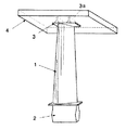
図4は、タービン動翼の模式的外観図である。タービン動翼は、翼部1、ダブテール部2及び先端部3からなる。翼部1は、翼形断面を有し、燃焼ガスにより回転動力を発生する部分である。ダブテール部2は、翼部1の末端部に位置し、図示しないタービンディスクに固定され、回転動力をタービンディスクに伝達する部分である。先端部3は、回転方向に延びる薄肉部分3aを有し、その先端がケーシング内面に近接してガス漏れを低減する機能を有する。
【0003】
高温、高圧の燃焼ガスが衝突するガスタービン動翼は、極めて過酷な条件下で使用される。そのため、動翼先端の薄肉部分3aは、運転中に摩耗、高温酸化による減肉、割れの発生などが生じることがある。このような場合、肉盛溶接により薄肉部の補修が行われる。
【0004】
従来のかかる肉盛溶接手段としては、特許文献1、特許文献2、等が開示されている。
【0005】
【特許文献1】
特開平7−171682号公報
【特許文献2】
特開平10−180442号公報
【0006】
特許文献1の「表面角部の肉盛溶接方法および肉盛溶接用治具」は、図5に示すように、肉盛溶接に先立って、被溶接材53の角面側53aに、冷却用肉盛溶接用治具51を当接させ、その後、角面側53bに肉盛溶接を行い、溶接ビード54の凝固終了後に肉盛溶接用治具51を被溶接材53から離すことを特徴とするものである。
【0007】
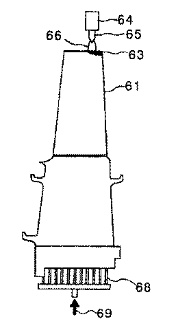
特許文献2の「ガスタービン翼の補修方法」は、図6に示すように、ガスタービン動翼の先端部を肉盛溶接によって補修する施工において、施工時に動翼内部の通気孔にガスあるいは流体を流しながら溶接することを特徴とするものである。なお、この図において、61はガスタービン動翼、63は肉盛溶接部、64は溶接トーチのノズル、65は溶接電極、66はアーク、68はガス又は流体の注入口、69はガス又は流体である。
【0008】
【発明が解決しようとする課題】
ガスタービン動翼には、従来主としてNi基合金が用いられていた。かかるNi基合金は、引張強度が高く、延びが大きいため、上述した肉盛溶接によっても欠陥が生じにくい利点があった。
【0009】
一方、近年、ガスタービンの性能向上のため、Ni基合金よりも比重が小さい金属(例えばTiAl合金)をガスタービン動翼に用いることが検討されている。TiAl合金は、比重がNi基合金の約半分であり、比強度が高いため、ガスタービン動翼に適用するとガスタービン動翼が取り付けられるタービンディスクに作用する遠心力を大幅に低減でき、ガスタービンをより高速化できる等の利点がある。
表1にNi基合金とTiAl合金の特性比較を示す。
【0010】
【表1】
しかし、TiAl合金製のガスタービン動翼において、従来と同様に肉盛溶接を薄肉部分に行うと、図7(A)(B)に示すように、薄肉部分3aの角部から溶融金属が垂れたり、角部がダレたりする問題点があった。
またこれを解決するために、特許文献1のように、冷却した治具を角面側に設置すると、TiAl合金の伸びが小さく、引張強度が低いため、熱応力により肉盛金属5に溶接割れが発生してしまう問題点があった。
なお、この図において、aはダレ部分、bは溶接割れ部分である。
【0012】
本発明は、かかる問題点を解決するために創案されたものである。すなわち、本発明の目的は、伸びが小さく、引張強度が低い材料からなる薄肉部分に、溶融金属に垂れや角部のダレを生じることなく、良好な肉盛溶接を行うことができる薄肉部分の肉盛溶接方法を提供することにある。
【0013】
【課題を解決するための手段】
本発明によれば、対象物の薄肉部分に密着し肉盛部分に溶融金属を溜める凹部を形成する溶融金属よりも耐熱温度が高い十分大きな熱容量を有する材料で作製した治具を対象物の薄肉部分に取り付ける治具取付けステップ(A)と、
前記治具が取り付けられた状態で、対象物及び前記治具を所定の温度まで予熱する予熱ステップ(B)と、
次いで、対象物の薄肉部分に肉盛溶接を行い肉盛部分に溶接ビードを形成する肉盛溶接ステップ(C)と、
次いで、溶接ビードの凝固終了後に前記治具を取り外す治具取外しステップ(D)とからなる、ことを特徴とする薄肉部分の肉盛溶接方法が提供される。
【0014】
本発明の好ましい実施形態によれば、前記十分大きな熱容量を有する材料で作製した治具は、セラミック治具である。
また、前記十分大きな熱容量を有する材料で作製した治具は、肉盛溶接後の薄肉部分の冷却速度を低減するのに十分大きな熱容量を有する。
また、前記十分大きな熱容量を有する材料で作製した治具は、対象物の薄肉部分に密着する形状を有する複数の密着セグメントと、該複数の密着セグメントの回りを囲みこれを一体に保持する外枠セグメントとからなる。
【0015】
前記対象物の材料はTiAl合金である、ことが好ましい。
また、前記対象物の薄肉部分はタービン翼先端部である、ことが好ましい。
【0016】
上記本発明の方法によれば、十分大きな熱容量を有する材料で作製した治具の耐熱温度が溶融金属よりも高く、かつ対象物の薄肉部分に密着し肉盛部分に溶融金属を溜める凹部を形成するので、この凹部が溶融金属の鋳型の役割をすることで、溶融金属の垂れ、角部のダレを抑え、求める形状を得ることができる。
また、この治具は十分大きな熱容量を有し、かつ対象物の薄肉部分に密着するので、保温効果が高い。
また、この治具が取り付けられた状態で、対象物及びこの治具を所定の温度まで予熱し、かつ溶接ビードの凝固終了後に治具を取り外すので、肉盛溶接後の薄肉部分の冷却速度を低減して、発生する熱応力を低減し溶接割れを起こしやすい材料であっても良好に肉盛溶接することができる。
【0017】
【発明の実施の形態】
以下、本発明の好ましい実施形態について図面を参照して説明する。なお、各図において共通する部分には同一の符号を付し、重複した説明を省略する。
【0018】
図1は、本発明に適用するセラミック治具の構造図である。この図に示すように、セラミック治具4は、複数(この例で5つ)の密着セグメント4a〜4eと外枠セグメント4fからなる。
各密着セグメント4a〜4eは、対象物(この例では、タービン翼先端部)の薄肉部分3a(斜線部)に密着する形状を有する。また、外枠セグメント4fの内面は、複数の密着セグメント4a〜4eの回りを囲み、これを一体に保持するようになっている。
【0019】
このセラミック治具4は、溶融金属よりも耐熱温度が高いセラミックスからなる。また、各密着セグメント4a〜4eは、薄肉部分よりも厚い板状であり、肉盛部分に溶融金属を溜める凹部を形成するようになっている。さらにこのセラミック治具4は、肉盛溶接後の薄肉部分の冷却速度を低減するように、全体が十分大きな熱容量を有するように設定されている。
【0020】
図2は、本発明の方法を模式的に示す図である。
本発明の肉盛溶接方法は、治具取付けステップ(A)、予熱ステップ(B)、肉盛溶接ステップ(C)及び治具取外しステップ(D)からなる。
【0021】
治具取付けステップ(A)において、図2に示すように、セラミック治具4を対象物の薄肉部分3aに密着させ、肉盛溶接を行う肉盛部分に溶融金属を溜める凹部が形成されるように取り付ける。
【0022】
予熱ステップ(B)では、セラミック治具4が取り付けられた状態で、対象物及びセラミック治具を所定の温度まで予熱する。この所定の温度は対象物の材料に適した予熱温度であり、例えば、TiAl合金の場合には、800℃以上、1000℃以下であるのがよい。この予熱は、加熱炉等を用いて全体を均一に加熱するのがよい。
【0023】
次いで、肉盛溶接ステップ(C)において、対象物の薄肉部分に肉盛溶接を行い、肉盛部分に溶接ビードを形成する。肉盛溶接に使用する材料は対象物と同一材料であるのが好ましいが、溶接が可能であれば異なる材料であってもよい。肉盛溶接は、好ましくはアーク溶接であるが、その他の溶接手段、例えばTIG溶接であってもよい。
【0024】
次いで、治具取外しステップ(D)では、溶接ビードの凝固終了後に治具4を対象物から取り外す。このステップは、図1に示したセラミック治具4の場合、まず外枠セグメント4fを内面に沿ってずらして外し、次いで、各密着セグメント4a〜4eを対象物の薄肉部分から分離することにより、容易に取り外すことができる。
【0025】
図3は、本発明による肉盛溶接結果を示す図である。この図において、(A)は先端部3の端面図、(B)は先端部3の斜視図である。この例では、TiAl合金製のタービン翼を対象とし、その先端の片方の薄肉部分に同一材料をアーク溶接により肉盛溶接したものである。なお予熱温度は900℃で実施した。
【0026】
図3と図7(従来例)との比較からわかるように、本発明による肉盛溶接方法により、溶融金属に垂れや角部のダレを生じることなく、良好な肉盛溶接を行うことができることが確認された。
【0027】
上述したように、本発明の方法によれば、セラミックス治具4の耐熱温度が溶融金属よりも高く、かつ対象物の薄肉部分3aに密着し、肉盛部分に溶融金属を溜める凹部を形成するので、この凹部が溶融金属の鋳型の役割をすることで、溶融金属の垂れ、角部のダレを抑え、求める形状を得ることができる。
また、セラミック治具4は十分大きな熱容量を有し、かつ対象物の薄肉部分3aに密着するので、保温効果が高い。
また、セラミック治具4が取り付けられた状態で、対象物及びセラミック治具を所定の温度まで予熱し、かつ溶接ビードの凝固終了後に治具を取り外すので、肉盛溶接後の薄肉部分3aの冷却速度を低減して、発生する熱応力を低減し溶接割れを起こしやすい材料であっても良好に肉盛溶接することができる。
【0028】
なお、本発明は上述した実施形態に限定されず、本発明の要旨を逸脱しない範囲で種々に変更できることは勿論である。
【0029】
【発明の効果】
上述したように、本発明の薄肉部分の肉盛溶接方法は、伸びが小さく、引張強度が低い材料からなる薄肉部分に、溶融金属に垂れや角部のダレを生じることなく、良好な肉盛溶接を行うことができる、等の優れた効果を有する。
【図面の簡単な説明】
【図1】本発明に適用するセラミック治具の構造図である。
【図2】本発明の方法を模式的に示す図である。
【図3】本発明による肉盛溶接結果を示す図である。
【図4】タービン動翼の模式的外観図である。
【図5】従来の肉盛溶接手段を示す図である。
【図6】従来の別の肉盛溶接手段を示す図である。
【図7】従来の肉盛溶接結果を示す図である。
【符号の説明】
1 翼部、2 ダブテール部、
3 先端部、3a 薄肉部分、
4 セラミック治具、
4a〜4e 密着セグメント、
4f 外枠セグメント、
5 肉盛金属[0001]
BACKGROUND OF THE INVENTION
The present invention relates to a build-up welding method for a thin-walled portion, and more particularly, to a repair method for a gas turbine rotor blade tip portion.
[0002]
[Prior art]
FIG. 4 is a schematic external view of the turbine rotor blade. The turbine blade includes a
[0003]
Gas turbine blades that collide with high-temperature, high-pressure combustion gas are used under extremely severe conditions. For this reason, the thin-
[0004]
As such conventional overlay welding means,
[0005]
[Patent Document 1]
JP-A-7-171682 [Patent Document 2]
JP-A-10-180442 [0006]
As shown in FIG. 5, the “surface corner welding method and build-up welding jig” of
[0007]
As shown in FIG. 6, “Repair method of gas turbine blade” in
[0008]
[Problems to be solved by the invention]
Conventionally, Ni-based alloys have been mainly used for gas turbine blades. Such a Ni-based alloy has a high tensile strength and a large elongation, and therefore has an advantage that defects are hardly generated even by the above-described overlay welding.
[0009]
On the other hand, in recent years, in order to improve the performance of a gas turbine, it has been studied to use a metal (for example, TiAl alloy) having a specific gravity smaller than that of a Ni-based alloy for a gas turbine rotor blade. The TiAl alloy has a specific gravity about half that of the Ni-based alloy and has a high specific strength. Therefore, when applied to a gas turbine blade, the centrifugal force acting on the turbine disk to which the gas turbine blade is mounted can be greatly reduced. There are advantages such as higher speed.
Table 1 shows a comparison of characteristics between Ni-base alloy and TiAl alloy.
[0010]
[Table 1]
However, in the gas turbine rotor blade made of TiAl alloy, when overlay welding is performed on a thin portion as in the conventional case, as shown in FIGS. 7A and 7B, molten metal drips from the corner of the
Moreover, in order to solve this, when the cooled jig | tool is installed in a square surface side like
In this figure, a is a sag portion and b is a weld crack portion.
[0012]
The present invention has been developed to solve such problems. That is, an object of the present invention is to provide a thin-walled portion that can be subjected to good build-up welding without causing dripping of the molten metal or sagging of a corner portion in a thin-walled portion made of a material having low elongation and low tensile strength. The object is to provide an overlay welding method.
[0013]
[Means for Solving the Problems]
According to the present invention, a jig made of a material having a sufficiently large heat capacity that is higher in heat resistance than a molten metal that forms a concave portion that adheres to a thin-walled portion of the object and accumulates the molten metal in the built-up portion is formed into a thin-walled object. A jig mounting step (A) to be attached to the part;
A preheating step (B) for preheating the object and the jig to a predetermined temperature in a state where the jig is attached;
Next, build-up welding step (C) of performing build-up welding on the thin-walled portion of the object and forming a weld bead on the build-up portion;
Next, there is provided a build-up welding method for a thin portion characterized by comprising a jig removing step (D) for removing the jig after completion of solidification of the weld bead.
[0014]
According to a preferred embodiment of the present invention, the jig made of the material having a sufficiently large heat capacity is a ceramic jig.
Moreover, the jig made of the material having a sufficiently large heat capacity has a sufficiently large heat capacity to reduce the cooling rate of the thin-walled portion after build-up welding.
In addition, the jig made of the material having a sufficiently large heat capacity includes a plurality of contact segments having a shape closely contacting a thin portion of an object, and an outer frame surrounding and surrounding the plurality of contact segments It consists of segments.
[0015]
The material of the object is preferably a TiAl alloy.
The thin portion of the object is preferably a turbine blade tip.
[0016]
According to the method of the present invention, a jig made of a material having a sufficiently large heat capacity has a heat resistance temperature higher than that of the molten metal, and forms a recess that adheres closely to the thin portion of the object and accumulates the molten metal in the build-up portion. Therefore, the concave portion serves as a mold for molten metal, so that drooping of the molten metal and sagging of corner portions can be suppressed and a desired shape can be obtained.
Moreover, since this jig has a sufficiently large heat capacity and is in close contact with the thin portion of the object, the heat retention effect is high.
In addition, with this jig attached, the object and this jig are preheated to a predetermined temperature, and the jig is removed after the solidification of the weld bead. Even if it is the material which reduces and reduces the thermal stress to generate | occur | produce and it is easy to raise | generate a weld crack, overlay welding can be performed favorably.
[0017]
DETAILED DESCRIPTION OF THE INVENTION
Hereinafter, preferred embodiments of the present invention will be described with reference to the drawings. In addition, the same code | symbol is attached | subjected to the common part in each figure, and the overlapping description is abbreviate | omitted.
[0018]
FIG. 1 is a structural diagram of a ceramic jig applied to the present invention. As shown in this figure, the ceramic jig 4 includes a plurality (five in this example) of
Each
[0019]
The ceramic jig 4 is made of a ceramic having a heat resistant temperature higher than that of the molten metal. Moreover, each contact |
[0020]
FIG. 2 is a diagram schematically showing the method of the present invention.
The build-up welding method of the present invention includes a jig attachment step (A), a preheating step (B), a build-up welding step (C), and a jig removal step (D).
[0021]
In the jig mounting step (A), as shown in FIG. 2, the ceramic jig 4 is brought into close contact with the thin-
[0022]
In the preheating step (B), the object and the ceramic jig are preheated to a predetermined temperature with the ceramic jig 4 attached. This predetermined temperature is a preheating temperature suitable for the material of the object. For example, in the case of a TiAl alloy, it is preferably 800 ° C. or higher and 1000 ° C. or lower. This preheating is preferably performed uniformly using a heating furnace or the like.
[0023]
Next, in the build-up welding step (C), build-up welding is performed on a thin portion of the object, and a weld bead is formed on the build-up portion. The material used for overlay welding is preferably the same material as the object, but may be a different material as long as welding is possible. The overlay welding is preferably arc welding, but may be other welding means such as TIG welding.
[0024]
Next, in the jig removing step (D), the jig 4 is removed from the object after the solidification of the weld bead. In the case of the ceramic jig 4 shown in FIG. 1, this step is performed by first displacing the
[0025]
FIG. 3 is a diagram showing the result of overlay welding according to the present invention. In this figure, (A) is an end view of the
[0026]
As can be seen from a comparison between FIG. 3 and FIG. 7 (conventional example), the overlay welding method according to the present invention can perform excellent overlay welding without causing dripping or sagging of the corners of the molten metal. Was confirmed.
[0027]
As described above, according to the method of the present invention, the heat resistance temperature of the ceramic jig 4 is higher than that of the molten metal, and the ceramic jig 4 is in close contact with the
Moreover, since the ceramic jig 4 has a sufficiently large heat capacity and is in close contact with the
In addition, with the ceramic jig 4 attached, the object and the ceramic jig are preheated to a predetermined temperature, and the jig is removed after solidification of the weld bead, so that the
[0028]
In addition, this invention is not limited to embodiment mentioned above, Of course, it can change variously in the range which does not deviate from the summary of this invention.
[0029]
【The invention's effect】
As described above, the overlay welding method of the thin wall portion according to the present invention has a good overlay without causing dripping of the molten metal or sagging of the corner portion in the thin wall portion made of a material having low elongation and low tensile strength. It has excellent effects such as being able to perform welding.
[Brief description of the drawings]
FIG. 1 is a structural diagram of a ceramic jig applied to the present invention.
FIG. 2 schematically shows the method of the present invention.
FIG. 3 is a diagram showing a result of overlay welding according to the present invention.
FIG. 4 is a schematic external view of a turbine rotor blade.
FIG. 5 is a view showing a conventional overlay welding means.
FIG. 6 is a view showing another conventional overlay welding means.
FIG. 7 is a diagram showing a result of conventional overlay welding.
[Explanation of symbols]
1 wing, 2 dovetail,
3 Tip, 3a Thin part,
4 Ceramic jig,
4a-4e adhesion segment,
4f outer frame segment,
5 overlay metal
Claims (6)
前記治具が取り付けられた状態で、対象物及び前記治具を所定の温度まで予熱する予熱ステップ(B)と、
次いで、対象物の薄肉部分に肉盛溶接を行い肉盛部分に溶接ビードを形成する肉盛溶接ステップ(C)と、
次いで、溶接ビードの凝固終了後に前記治具を取り外す治具取外しステップ(D)とからなる、ことを特徴とする薄肉部分の肉盛溶接方法。Jig attachment for attaching a jig made of a material having a sufficiently large heat capacity, which has a heat resistance higher than that of the molten metal, in close contact with the thin part of the object and forming a recess for accumulating the molten metal in the built-up part. Step (A);
A preheating step (B) for preheating the object and the jig to a predetermined temperature in a state where the jig is attached;
Next, build-up welding step (C) of performing build-up welding on the thin-walled portion of the object and forming a weld bead on the build-up portion;
Next, a build-up welding method for thin-walled parts, comprising: a jig removing step (D) for removing the jig after completion of solidification of the weld bead.
Priority Applications (4)
| Application Number | Priority Date | Filing Date | Title |
|---|---|---|---|
| JP2003077247A JP4229734B2 (en) | 2003-03-20 | 2003-03-20 | Overlay welding method for thin parts |
| US10/651,203 US6991150B2 (en) | 2003-03-20 | 2003-08-29 | Method of build up welding to thin-walled portion |
| EP03019773A EP1459829B1 (en) | 2003-03-20 | 2003-08-29 | Method of build up welding to thin-walled portion |
| DE60319948T DE60319948T2 (en) | 2003-03-20 | 2003-08-29 | Method for build-up welding thin-walled parts |
Applications Claiming Priority (1)
| Application Number | Priority Date | Filing Date | Title |
|---|---|---|---|
| JP2003077247A JP4229734B2 (en) | 2003-03-20 | 2003-03-20 | Overlay welding method for thin parts |
Publications (2)
| Publication Number | Publication Date |
|---|---|
| JP2004283852A true JP2004283852A (en) | 2004-10-14 |
| JP4229734B2 JP4229734B2 (en) | 2009-02-25 |
Family
ID=32821373
Family Applications (1)
| Application Number | Title | Priority Date | Filing Date |
|---|---|---|---|
| JP2003077247A Expired - Fee Related JP4229734B2 (en) | 2003-03-20 | 2003-03-20 | Overlay welding method for thin parts |
Country Status (4)
| Country | Link |
|---|---|
| US (1) | US6991150B2 (en) |
| EP (1) | EP1459829B1 (en) |
| JP (1) | JP4229734B2 (en) |
| DE (1) | DE60319948T2 (en) |
Cited By (3)
| Publication number | Priority date | Publication date | Assignee | Title |
|---|---|---|---|---|
| JP2006167756A (en) * | 2004-12-15 | 2006-06-29 | Mitsubishi Heavy Ind Ltd | Laser beam welding apparatus, and method for manufacturing welded structure |
| JP2010069439A (en) * | 2008-09-19 | 2010-04-02 | Hitachi Constr Mach Co Ltd | Repairing jig of crushing claw and repairing method thereof |
| JP2015534507A (en) * | 2012-08-10 | 2015-12-03 | シーメンス エナジー インコーポレイテッド | Superalloy components and electroslag and electrogas repair of superalloy components |
Families Citing this family (13)
| Publication number | Priority date | Publication date | Assignee | Title |
|---|---|---|---|---|
| JP4229734B2 (en) * | 2003-03-20 | 2009-02-25 | 株式会社Ihi | Overlay welding method for thin parts |
| DE102004032975A1 (en) * | 2004-07-08 | 2006-02-09 | Mtu Aero Engines Gmbh | A method of joining vane blades to vane roots or rotor disks in the manufacture and / or repair of gas turbine blades or integrally bladed gas turbine rotors |
| US8925200B2 (en) * | 2008-03-27 | 2015-01-06 | United Technologies Corporation | Method for repairing an airfoil |
| DE102010026084A1 (en) * | 2010-07-05 | 2012-01-05 | Mtu Aero Engines Gmbh | Applying material layer on workpiece made of material containing titanium aluminide, comprises heating workpiece by induction at preheating temperature and applying powdery additive on heated surface of workpiece by deposition welding |
| US10201877B2 (en) | 2011-10-26 | 2019-02-12 | Titanova Inc | Puddle forming and shaping with primary and secondary lasers |
| WO2014134041A1 (en) | 2013-02-28 | 2014-09-04 | United Technologies Corporation | System and method low heat weld |
| US20150314403A1 (en) * | 2014-05-01 | 2015-11-05 | Siemens Energy, Inc. | Arrangement for laser processing of turbine component |
| CN104874937B (en) * | 2015-06-15 | 2017-12-05 | 唐山师范学院 | Bainite heat resisting steel 12Cr2MoWVTiB welding procedure |
| US11154956B2 (en) * | 2017-02-22 | 2021-10-26 | General Electric Company | Method of repairing turbine component using ultra-thin plate |
| US10717130B2 (en) | 2017-02-22 | 2020-07-21 | General Electric Company | Method of manufacturing turbine airfoil and tip component thereof |
| US10702958B2 (en) | 2017-02-22 | 2020-07-07 | General Electric Company | Method of manufacturing turbine airfoil and tip component thereof using ceramic core with witness feature |
| JP7185212B2 (en) * | 2018-02-07 | 2022-12-07 | 住友重機械ハイマテックス株式会社 | Tool material recycling method |
| FR3101663B1 (en) * | 2019-10-07 | 2021-10-01 | Safran Aircraft Engines | PROCESS FOR RELOADING AN AIRCRAFT TURBOMACHINE BLADE |
Family Cites Families (23)
| Publication number | Priority date | Publication date | Assignee | Title |
|---|---|---|---|---|
| US3634649A (en) * | 1970-03-19 | 1972-01-11 | Reynolds Metals Co | Apparatus for and method of joining stranded cable |
| US3821840A (en) * | 1972-11-29 | 1974-07-02 | Teegarden P | Railway frog repair method and apparatus |
| US4298154A (en) * | 1980-01-14 | 1981-11-03 | B. B. Greenberg Company | Automatic soldering machine |
| JPS62267079A (en) * | 1986-05-15 | 1987-11-19 | Kobe Steel Ltd | Roll automatic build-up welding method |
| JPS62282796A (en) * | 1986-05-29 | 1987-12-08 | Mitsubishi Heavy Ind Ltd | Welding repair method for blade root part |
| EP0276404B1 (en) * | 1986-12-12 | 1992-06-03 | BBC Brown Boveri AG | Process for lengthening a turbo machine blade |
| US4927992A (en) * | 1987-03-04 | 1990-05-22 | Westinghouse Electric Corp. | Energy beam casting of metal articles |
| US5014901A (en) * | 1989-06-26 | 1991-05-14 | Foster Wheeler Energy Corporation | Rotatable welding fixture and method for metal cladding tubular membrane panels |
| US4982066A (en) * | 1989-12-11 | 1991-01-01 | Bird-Johnson Company | Method of rehabilitating propeller hub bodies |
| DE4141927C2 (en) * | 1991-12-19 | 1995-06-14 | Mtu Maintenance Gmbh | Method and device for welding workpieces |
| JPH07171682A (en) | 1993-12-17 | 1995-07-11 | Japan Steel Works Ltd:The | Cladding by welding method of surface corner and jig therefor |
| US5811756A (en) * | 1995-01-23 | 1998-09-22 | Nippon Light Metal Company, Inc. | ARC welding method for aluminum members and welded product excellent in dimensional accuracy and external appearance |
| US5553370A (en) * | 1995-02-09 | 1996-09-10 | Pepe; John | Method for repair of steam turbine blades |
| JPH10180442A (en) | 1996-12-25 | 1998-07-07 | Hitachi Ltd | Method for repairing gas turbine blade |
| US6034344A (en) * | 1997-12-19 | 2000-03-07 | United Technologies Corp. | Method for applying material to a face of a flow directing assembly for a gas turbine engine |
| US6054672A (en) * | 1998-09-15 | 2000-04-25 | Chromalloy Gas Turbine Corporation | Laser welding superalloy articles |
| JP4430769B2 (en) * | 1999-12-09 | 2010-03-10 | 信越化学工業株式会社 | Ceramic heating jig |
| US6333484B1 (en) * | 2000-03-17 | 2001-12-25 | Chromalloy Gas Turbine Corporation | Welding superalloy articles |
| US6376801B1 (en) * | 2000-10-12 | 2002-04-23 | General Electric Company | Gas turbine component refurbishment apparatus and repair method |
| US6607114B2 (en) * | 2001-10-12 | 2003-08-19 | General Electric Company | Weld fixture and method for repairing annular components |
| US6742698B2 (en) | 2002-06-10 | 2004-06-01 | United Technologies Corporation | Refractory metal backing material for weld repair |
| US6727459B1 (en) * | 2003-02-28 | 2004-04-27 | Liburdi Engineering Limited | Method for metal deposition on an edge |
| JP4229734B2 (en) * | 2003-03-20 | 2009-02-25 | 株式会社Ihi | Overlay welding method for thin parts |
-
2003
- 2003-03-20 JP JP2003077247A patent/JP4229734B2/en not_active Expired - Fee Related
- 2003-08-29 DE DE60319948T patent/DE60319948T2/en not_active Expired - Lifetime
- 2003-08-29 US US10/651,203 patent/US6991150B2/en not_active Expired - Lifetime
- 2003-08-29 EP EP03019773A patent/EP1459829B1/en not_active Expired - Lifetime
Cited By (3)
| Publication number | Priority date | Publication date | Assignee | Title |
|---|---|---|---|---|
| JP2006167756A (en) * | 2004-12-15 | 2006-06-29 | Mitsubishi Heavy Ind Ltd | Laser beam welding apparatus, and method for manufacturing welded structure |
| JP2010069439A (en) * | 2008-09-19 | 2010-04-02 | Hitachi Constr Mach Co Ltd | Repairing jig of crushing claw and repairing method thereof |
| JP2015534507A (en) * | 2012-08-10 | 2015-12-03 | シーメンス エナジー インコーポレイテッド | Superalloy components and electroslag and electrogas repair of superalloy components |
Also Published As
| Publication number | Publication date |
|---|---|
| JP4229734B2 (en) | 2009-02-25 |
| US6991150B2 (en) | 2006-01-31 |
| EP1459829B1 (en) | 2008-03-26 |
| EP1459829A1 (en) | 2004-09-22 |
| US20050173496A1 (en) | 2005-08-11 |
| DE60319948D1 (en) | 2008-05-08 |
| DE60319948T2 (en) | 2008-07-03 |
Similar Documents
| Publication | Publication Date | Title |
|---|---|---|
| JP4229734B2 (en) | Overlay welding method for thin parts | |
| JP5887052B2 (en) | Method of welding a single crystal turbine blade tip with an oxidation resistant filler material | |
| US9951632B2 (en) | Hybrid bonded turbine rotors and methods for manufacturing the same | |
| EP1775054B1 (en) | Weld closure of through-holes in a nickel-base superalloy hollow airfoil | |
| US6742698B2 (en) | Refractory metal backing material for weld repair | |
| EP2995410A1 (en) | Method of blade tip repair | |
| US20100200189A1 (en) | Method of fabricating turbine airfoils and tip structures therefor | |
| US20080128475A1 (en) | Nickel-based braze alloy compositions and related processes and articles | |
| JP2004216457A (en) | Method of weld repairing component and component repaired thereby | |
| JP2003507614A (en) | How to Replace Airfoil on Turbine Blade | |
| US9186740B2 (en) | Projection resistance brazing of superalloys | |
| JP5451463B2 (en) | Method for manufacturing turbine airfoil and tip structure thereof | |
| US10119408B2 (en) | Method for connecting a turbine blade or vane to a turbine disc or a turbine ring | |
| JP2019089127A (en) | Method for forming article, method for forming turbine bucket, and turbine bucket | |
| JP2015534507A (en) | Superalloy components and electroslag and electrogas repair of superalloy components | |
| JP4865206B2 (en) | Fusion welding method and welded article | |
| JP2011079056A (en) | Method for removal of brazed metal sheet from partial assembly | |
| JP5535799B2 (en) | Repair method of metal parts and repaired metal parts | |
| CN104619450A (en) | Stud welding repair of superalloy components | |
| US6996906B2 (en) | Method of repairing a turbine blade and blade repaired thereby | |
| EP2412930B1 (en) | Turbine nozzle segment and method of repairing same | |
| EP3366415B1 (en) | Method of brazing a treatment area of a load-bearing gas turbine component | |
| EP1867409A1 (en) | Investment cast article and method of production thereof | |
| CN114833412A (en) | Brazing method of DD6 single crystal and GH3536 alloy | |
| US11982207B2 (en) | Tip repair of a turbine component using a composite tip boron base pre-sintered preform |
Legal Events
| Date | Code | Title | Description |
|---|---|---|---|
| A621 | Written request for application examination |
Free format text: JAPANESE INTERMEDIATE CODE: A621 Effective date: 20051121 |
|
| A977 | Report on retrieval |
Free format text: JAPANESE INTERMEDIATE CODE: A971007 Effective date: 20070418 |
|
| A131 | Notification of reasons for refusal |
Free format text: JAPANESE INTERMEDIATE CODE: A131 Effective date: 20070423 |
|
| A521 | Request for written amendment filed |
Free format text: JAPANESE INTERMEDIATE CODE: A523 Effective date: 20070620 |
|
| A02 | Decision of refusal |
Free format text: JAPANESE INTERMEDIATE CODE: A02 Effective date: 20070717 |
|
| A521 | Request for written amendment filed |
Free format text: JAPANESE INTERMEDIATE CODE: A523 Effective date: 20070813 |
|
| A911 | Transfer to examiner for re-examination before appeal (zenchi) |
Free format text: JAPANESE INTERMEDIATE CODE: A911 Effective date: 20070918 |
|
| TRDD | Decision of grant or rejection written | ||
| A01 | Written decision to grant a patent or to grant a registration (utility model) |
Free format text: JAPANESE INTERMEDIATE CODE: A01 Effective date: 20081202 |
|
| A01 | Written decision to grant a patent or to grant a registration (utility model) |
Free format text: JAPANESE INTERMEDIATE CODE: A01 |
|
| A61 | First payment of annual fees (during grant procedure) |
Free format text: JAPANESE INTERMEDIATE CODE: A61 Effective date: 20081202 |
|
| R150 | Certificate of patent or registration of utility model |
Free format text: JAPANESE INTERMEDIATE CODE: R150 Ref document number: 4229734 Country of ref document: JP Free format text: JAPANESE INTERMEDIATE CODE: R150 |
|
| FPAY | Renewal fee payment (event date is renewal date of database) |
Free format text: PAYMENT UNTIL: 20111212 Year of fee payment: 3 |
|
| FPAY | Renewal fee payment (event date is renewal date of database) |
Free format text: PAYMENT UNTIL: 20121212 Year of fee payment: 4 |
|
| R250 | Receipt of annual fees |
Free format text: JAPANESE INTERMEDIATE CODE: R250 |
|
| FPAY | Renewal fee payment (event date is renewal date of database) |
Free format text: PAYMENT UNTIL: 20121212 Year of fee payment: 4 |
|
| FPAY | Renewal fee payment (event date is renewal date of database) |
Free format text: PAYMENT UNTIL: 20131212 Year of fee payment: 5 |
|
| R250 | Receipt of annual fees |
Free format text: JAPANESE INTERMEDIATE CODE: R250 |
|
| R250 | Receipt of annual fees |
Free format text: JAPANESE INTERMEDIATE CODE: R250 |
|
| S111 | Request for change of ownership or part of ownership |
Free format text: JAPANESE INTERMEDIATE CODE: R313117 |
|
| R350 | Written notification of registration of transfer |
Free format text: JAPANESE INTERMEDIATE CODE: R350 |
|
| R250 | Receipt of annual fees |
Free format text: JAPANESE INTERMEDIATE CODE: R250 |
|
| R250 | Receipt of annual fees |
Free format text: JAPANESE INTERMEDIATE CODE: R250 |
|
| LAPS | Cancellation because of no payment of annual fees |