JP2004278564A - Diaphragm valve - Google Patents
Diaphragm valve Download PDFInfo
- Publication number
- JP2004278564A JP2004278564A JP2003067409A JP2003067409A JP2004278564A JP 2004278564 A JP2004278564 A JP 2004278564A JP 2003067409 A JP2003067409 A JP 2003067409A JP 2003067409 A JP2003067409 A JP 2003067409A JP 2004278564 A JP2004278564 A JP 2004278564A
- Authority
- JP
- Japan
- Prior art keywords
- film
- diaphragm
- liquid
- valve
- backup
- Prior art date
- Legal status (The legal status is an assumption and is not a legal conclusion. Google has not performed a legal analysis and makes no representation as to the accuracy of the status listed.)
- Pending
Links
Images

Landscapes
- Details Of Valves (AREA)
- Examining Or Testing Airtightness (AREA)
- Indication Of The Valve Opening Or Closing Status (AREA)
Abstract
Description
【0001】
【発明の属する技術分野】
本発明は、食品工業や医薬品工業等における各種液体配管において、その液体配管の流路を開閉するのに使用されるダイアフラム弁に関するものである。
【0002】
【従来の技術及びその課題】
この種のダイアフラム弁では、弁ボディ内の弁座と対向する位置に、弁体を形成するダイアフラムが、接液する表面側とその背面側とを遮断するように取り付けられ、その背面側中央部に連結された作動軸の軸方向進退駆動により、ダイアフラムの表面側が弁座に対し離接して流路を開閉するようになっている。しかして、このようなダイヤフラム弁にあっては、ダイヤフラムは表面側と作動機構を有する背面側とが周縁部の固定部分で完全に遮断されて常時表面側のみで接液し、且つダイヤフラムの変形のみで弁作動が行われ、他の各種弁の弁軸部のような液洩れを生じ易いような摺接部分が存在せず、弁部での封止性が高いため、特に安全及び衛生面での高信頼性が要求される食品や薬品分野で賞用されている。
【0003】
ところで、輸液の製造ライン、即ち純水ライン等で用いられるダイアフラム弁のダイアフラムが、疲労その他の要因によって破損した場合には、不良輸液を製造継続しないためにも、その破損を検知する機能が必要となる。従来では、ダイアフラムが破損しないうちに早目にダイヤフラムを定期交換する手法が採用されているが、このような早期交換ではまだ充分に長期使用に耐え得る状態のダイヤフラムも廃棄されることになって不経済であった。
【0004】
また、ダイアフラムに導電性ゴム層を設けて液洩れを電気的に検出するようにした漏洩検知センサーを備えたダイアフラム弁が知られているが、医薬品工業における純水ライン等にあっては、純水そのものが、導電性が極めて悪いため、正確な液洩れ検出が行えず、実用性に乏しかった。さらに、ダイアフラムの損傷部から漏れた漏液をダイアフラムの背面側に溜め、この漏液が一定量溜まることによって漏洩を検知するようにしたダイアフラム弁もあるが、これでは、漏れ始めから一定量が溜まるまで漏洩を検知できないという問題がある。
【0005】
本発明は、上記の問題点に鑑み、純水のように導電性の極めて悪い液体の場合でも、その液漏れを確実に検知できると共に、液体が漏れ始めた時点から直ちにその漏れを検知できるダイアフラム弁を提供することを目的とする。
【0006】
【課題を解決するための手段】
請求項1に係る発明のダイアフラム弁は、弁ボディ1内の弁座3と対向する位置に、本体膜5aとこれの裏側に重合されるバックアップ膜5bとからなるダイアフラム5を、接液する表面側とその背面側とを遮断するように取り付け、ダイアフラム5の表面側を弁座3に対し接離して流路を開閉するようにしたダイアフラム弁において、本体膜5aが損傷してその損傷部10から本体膜5aの背面側に漏れた液体を吸収して変色することにより漏洩を検知する漏洩検知手段を、その一部が弁外部に見えるようにダイアフラム5のバックアップ膜5b側に設けてなることを特徴とする。
【0007】
請求項2は、請求項1に記載のダイアフラム弁において、前記漏洩検知手段は、液体を吸収して変色する吸液変色剤を含む合成樹脂によって形成され、バックアップ膜5bの表面に重合される漏洩検知膜9からなることを特徴とする。
【0008】
請求項3は、請求項1に記載のダイアフラム弁において、前記漏洩検知手段は、液体を吸収して変色する吸液変色剤を含む合成樹脂をバックアップ膜5bの表面にコーティングすることによって形成される漏洩検知層からなることを特徴とする。
【0009】
請求項4は、請求項1に記載のダイアフラム弁において、前記漏洩検知手段は、液体を吸収して変色する吸液変色剤を含む合成樹脂によって形成されたバックアップ膜5bからなることを特徴とする。
【0010】
【発明の実施の形態】
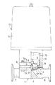
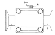
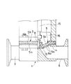
図1は本発明に係るダイアフラム弁の半縦断面正面図、図2はその底面図である。これらの図において、1は円管状の弁ボディで、この弁ボディ1内には長手方向中央部に凸状部2が形成され、この凸状部2の頂部が弁座3となっている。4は弁体を形成するダイアフラム5の表面周縁部を取り付けるためのダイアフラム取付座で、弁ボディ1の側壁部1aに形成され、このダイアフラム取付座4の内側には凸状部2を挟んでその両側に形成される出入管部6,7に通じる弁口6a,7aが開口している。
【0011】
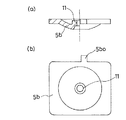
ダイアフラム5は、フッ素樹脂製の薄い本体膜5aと、この本体膜5aの裏側に重合配置される合成ゴム製の厚いバックアップ膜5bと、からなるもので、両膜5a,5bはその中心部に取り付けられた連結軸8によって連結されている。本体膜5aは、フッ素樹脂であるテフロン(登録商標)によって厚さ1mm程度の方形状に形成されている。バックアップ膜5bは、図3の(a) 及び(b) に示しているが、温度変化に強い軟質の合成樹脂によって、厚さ4mm程度の方形状に形成されている。図2中の5aoは、使用時に外部に突出する本体膜5aの耳片を示す。また図3の(b) において、5boは使用時に外部に突出するバックアップ膜5bの耳片、11は連結軸8を通す孔を示す。
【0012】
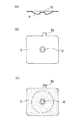
また図1において、9は本体膜5aが損傷してその損傷部から本体膜5aの背面側に漏れた液体を吸収して変色することにより漏洩を検知する漏洩検知手段としての漏洩検知膜で、外周部が露出してダイアフラム弁の外部から見えるようにダイアフラム5のバックアップ膜5b側に設けられている。この漏洩検知膜9は、液体を吸収して変色する吸液変色剤を含む合成樹脂によって、図4の(a) 及び(b) に示すような方形状の薄い膜状に形成され、バックアップ膜5bの表面に重合配置されるようになっている。図2及び図4の(a) 〜(c) において、9oは使用時に外部に突出する漏洩検知膜9の耳片を示し、また12は連結軸8を通す孔を示す。
【0013】
吸液変色剤としては、例えば塩化コバルトや有機系色素がある。吸液変色剤に塩化コバルトを使用して漏洩検知膜9を形成した場合、漏洩検知膜9は、吸液前はブルーであるが、吸液後はピンクに変色する。尚、図4の (b) は、吸液前の漏洩検知膜9を示す底面図であり、(c) は吸液後変色した漏洩検知膜9を示す底面図で、漏洩検知膜9の全体を梨地模様で示している。
【0014】
また図1において、13は弁操作部を構成するエアシリンダで、このシリンダ13は、シリンダ本体14とピストン(図示省略)とピストンロッド15とからなり、ピストンロッド15がダイアフラム弁の作動軸を形成する。このピストンロッド(作動軸)15の下端部がリテーナ16に連結され、このリテーナ16とダイアフラム5とが連結軸8を介して一体的に結合されている。しかして、ピストンロッド15の軸方向進退駆動によって、ダイアフラム5が、図1の実線図示のように弁座3に接した閉弁形態と、図示は省略するが弁座3から離間した開弁形態とに形態変換するようになっている。
【0015】
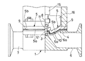
上記のように構成されるダイアフラム弁を各種液体配管に使用した時に、図5に示すように、ダイアフラム5の本体膜5aにクラック10が生じた場合には、管路6内の液体は、そのクラック10から本体膜5aの裏側に漏れて、バックアップ膜5b側の漏洩検知膜9に吸収される。こうして本体膜5aから漏れ出た液体を吸収した漏洩検知膜9は、これに含まれる吸液変色剤によって膜全体が変色し、しかしてこの検知膜9の外周面及び耳片9oが弁外部に露出しているから、これによって液体の漏洩が早期に検知される。図5は漏洩検知膜9が変色した状態を示すダイアフラム弁の半縦断面正面図、図6は底面図であり、この図6には外部に突出した耳片9oが変色した状態を示している。
【0016】
以上の図1〜図6によって説明した実施形態の漏洩検知手段は、液体を吸収して変色する吸液変色剤を含む合成樹脂により形成されて、バックアップ膜5bの表面に重合される漏洩検知膜からなるものであるが、図7は、漏洩検知手段が、液体を吸収して変色する吸液変色剤を含む合成樹脂によって一体形成されたバックアップ膜5bからなる実施形態を示す。
【0017】
このバックアップ膜5bからなる漏洩検知手段において、ダイアフラム5の本体膜5aにクラック10が生じた場合も、本体膜5aからの漏洩液体は、クラック10から本体膜5aの裏側に漏出してバックアップ膜5bに直接吸収される。こうして管路6から漏れた液体を吸収したバックアップ膜5bは、これに含まれる吸液変色剤によって膜全体が変色し、バックアップ膜5bの外周面及び耳片5bo(図示せず)が弁外部に露出しているから、これによって液体の漏洩を早期に検知することができる。
【0018】
上記のように漏洩検知手段がバックアップ膜5bからなる場合には、膜厚が厚く、弁の外部に露出する外周面の面積を十分に広くとれるから、漏洩時の変色状態を確認し易く、漏洩の早期検知が一層容易となると共に、ダイアフラム5を本体膜5aとバックアップ膜5bとの2枚だけで形成できるため、ダイアフラム弁の組立が容易となる。
【0019】
他の漏洩検知手段としては、図示は省略するが、液体を吸収して変色する吸液変色剤を含む合成樹脂をバックアップ膜の表面にコーティングすることによって形成される漏洩検知層からなるものでもよい。この漏洩検知層からなる漏洩検知手段の検出方法は、上記した漏洩検知膜9やバックアップ膜5bからなるものと同じある。この漏洩検知層からなる漏洩検知手段の場合も、ダイアフラム5を、本体膜5aと、表面側に漏洩検知層をコーティングしたバックアップ膜5bとの2枚だけで形成できるから、ダイアフラム弁の組立が容易となる。
【0020】
また、上述した漏洩検知膜9やバックアップ膜5bや漏洩検知層からなる漏洩検知手段を備えた本発明に係るダイアフラム弁によれば、本体膜5aが損傷してその損傷部から本体膜5aの背面側に漏れた液体を漏洩検知手段が吸収して変色することにより、漏液を検知するようになっているから、純水のように導電性の極めて悪い液体の場合でも、液漏れを確実に検知できると共に、その液漏れを早期に検知することができる。
【0021】
【発明の効果】
請求項1に係る発明によれば、本体膜の損傷部から本体膜の背面側に漏れた液体を吸収して変色することにより漏洩を検知する漏洩検知手段を、その一部が弁外部に見えるようにダイアフラムのバックアップ膜側に設けているから、液体の漏洩を早期に検知することができ、また純水のように導電性の極めて悪い液体の場合でも、液漏れを確実に検知できる。
【0022】
漏洩検知手段としては、請求項2に記載のように、液体を吸収して変色する吸液変色剤を含む合成樹脂で形成されて、バックアップ膜の表面に重合されるものでもよいし、請求項3に記載のように、液体を吸収して変色する吸液変色剤を含む合成樹脂をバックアップ膜の表面にコーティングすることによって形成される漏洩検知層からなるものでもよく、また請求項4に記載のように、液体を吸収して変色する吸液変色剤を含む合成樹脂によって形成されたバックアップ膜からなるものでもよい。
【0023】
漏洩検知手段が請求項4に記載のようなバックアップ膜からなる場合には、膜厚が厚く、弁の外部に露出する面積を十分に広くとれるから、漏洩時の変色状態を確認し易く、漏洩の早期検知が一層容易となると共に、ダイアフラムを本体膜とバックアップ膜との2枚だけで形成できるため、ダイアフラム弁の組立が容易となる。
【図面の簡単な説明】
【図1】本発明に係るダイアフラム弁の半縦断面正面図である。
【図2】図1に示すダイアフラム弁の底面図である。
【図3】(a) は図1に示すダイアフラム弁のバックアップ膜の半縦断面図
、(b) は同バックアップ膜の底面図である。
【図4】(a) は漏洩検知手段としての漏洩検知膜を示す縦断面図、(b) は
漏洩検知膜の底面図、(c) は変色した漏洩検知膜を示す底面図である。
【図5】図5は漏洩検知膜が変色した状態を示すダイアフラム弁の半縦断
面正面図である。
【図6】同ダイアフラム弁の底面図である。
【図7】漏洩検知手段がバックアップ膜からなる場合の実施形態を示すダ
イアフラム弁の半縦断面正面図である。
【符号の説明】
1 弁ボディ
3 弁座
5 ダイアフラム
5a 本体膜
5b バックアップ膜
9 漏洩検知膜
10 クラック(損傷部)[0001]
TECHNICAL FIELD OF THE INVENTION
The present invention relates to a diaphragm valve used for opening and closing a flow path of a liquid pipe in various liquid pipes in the food industry, the pharmaceutical industry, and the like.
[0002]
[Prior art and its problems]
In this type of diaphragm valve, a diaphragm forming a valve body is attached at a position facing a valve seat in a valve body so as to shut off a surface side in contact with liquid and a rear side thereof, and a central portion on a rear side thereof. The front surface side of the diaphragm comes into contact with the valve seat to open and close the flow path by the axially moving drive of the operating shaft connected to the valve shaft. However, in such a diaphragm valve, the diaphragm is completely shut off from the front side and the back side having the operating mechanism at the fixed portion of the peripheral portion, and is always in contact with the liquid only on the front side, and the diaphragm is deformed. The valve is operated only by itself, and there is no sliding part that easily leaks like the valve stem of other various valves, and the sealing performance at the valve is high. It has been awarded in the fields of food and medicine where high reliability is required.
[0003]
By the way, if the diaphragm of a diaphragm valve used in an infusion production line, that is, a pure water line, is broken due to fatigue or other factors, a function to detect the breakage is necessary in order not to continue manufacturing a defective infusion. It becomes. Conventionally, a method has been adopted in which the diaphragm is periodically replaced as early as possible before the diaphragm is damaged, but such an early replacement will result in the disposal of a diaphragm that can withstand long-term use. It was uneconomic.
[0004]
Further, a diaphragm valve provided with a leak detection sensor that electrically detects liquid leakage by providing a conductive rubber layer on the diaphragm is known, but in a pure water line or the like in the pharmaceutical industry, pure water is used. Since water itself has extremely poor conductivity, accurate detection of liquid leakage could not be performed, and the utility was poor. Further, there is a diaphragm valve that collects leaked liquid leaked from a damaged portion of the diaphragm on the rear side of the diaphragm and detects leakage by collecting a fixed amount of the leaked liquid. There is a problem that leaks cannot be detected until they accumulate.
[0005]
The present invention has been made in view of the above-described problems, and even in the case of a liquid having extremely poor conductivity such as pure water, a diaphragm that can reliably detect a liquid leak and detect the leak immediately after the liquid starts to leak. The purpose is to provide a valve.
[0006]
[Means for Solving the Problems]
The diaphragm valve according to the first aspect of the present invention has a surface in which the
[0007]
According to a second aspect of the present invention, in the diaphragm valve according to the first aspect, the leak detecting means is formed of a synthetic resin containing a liquid absorbing and discoloring agent that absorbs liquid and changes color, and is polymerized on the surface of the
[0008]
According to a third aspect, in the diaphragm valve according to the first aspect, the leak detecting means is formed by coating a synthetic resin containing a liquid absorbing and discoloring agent that absorbs liquid and changes color to the surface of the
[0009]
According to a fourth aspect of the present invention, in the diaphragm valve according to the first aspect, the leak detecting means is formed of a
[0010]
BEST MODE FOR CARRYING OUT THE INVENTION
FIG. 1 is a front view in a half longitudinal section of a diaphragm valve according to the present invention, and FIG. 2 is a bottom view thereof. In these figures, reference numeral 1 denotes a cylindrical valve body, in which a
[0011]
The
[0012]
In FIG. 1,
[0013]
Examples of the liquid absorbing color changing agent include cobalt chloride and organic dyes. When the
[0014]
In FIG. 1,
[0015]
When a
[0016]
The leak detecting means of the embodiment described with reference to FIGS. 1 to 6 is formed of a synthetic resin containing a liquid absorbing and discoloring agent that absorbs liquid and changes color, and is polymerized on the surface of the
[0017]
In the leak detecting means including the
[0018]
When the leak detecting means is made up of the
[0019]
As another leak detecting means, although not shown, a leak detecting layer formed by coating the surface of the backup film with a synthetic resin containing a liquid absorbing and discoloring agent that absorbs liquid and changes color may be used. . The detection method of the leak detecting means including the leak detecting layer is the same as the method including the above-described
[0020]
Further, according to the diaphragm valve according to the present invention including the above-described
[0021]
【The invention's effect】
According to the first aspect of the present invention, the leak detecting means for detecting the leak by absorbing the liquid leaking from the damaged portion of the main body film to the rear side of the main body film and discoloring the part thereof is partially visible outside the valve. Thus, since it is provided on the backup film side of the diaphragm, the leakage of the liquid can be detected at an early stage, and the liquid leakage can be reliably detected even in the case of a very poorly conductive liquid such as pure water.
[0022]
The leak detecting means may be formed of a synthetic resin containing a liquid absorbing and discoloring agent that absorbs liquid and changes its color, and is polymerized on the surface of the backup film. As set forth in
[0023]
In the case where the leak detecting means is made of the backup film as described in
[Brief description of the drawings]
FIG. 1 is a front view in a semi-longitudinal section of a diaphragm valve according to the present invention.
FIG. 2 is a bottom view of the diaphragm valve shown in FIG.
3A is a semi-longitudinal sectional view of a backup film of the diaphragm valve shown in FIG. 1, and FIG. 3B is a bottom view of the backup film.
4A is a longitudinal sectional view showing a leak detecting film as a leak detecting means, FIG. 4B is a bottom view of the leak detecting film, and FIG. 4C is a bottom view showing the discolored leak detecting film.
FIG. 5 is a semi-longitudinal sectional front view of the diaphragm valve showing a state in which the leakage detection film has changed color.
FIG. 6 is a bottom view of the diaphragm valve.
FIG. 7 is a semi-longitudinal sectional front view of a diaphragm valve showing an embodiment in which the leak detecting means is formed of a backup film.
[Explanation of symbols]
DESCRIPTION OF SYMBOLS 1
Claims (4)
Priority Applications (1)
| Application Number | Priority Date | Filing Date | Title |
|---|---|---|---|
| JP2003067409A JP2004278564A (en) | 2003-03-13 | 2003-03-13 | Diaphragm valve |
Applications Claiming Priority (1)
| Application Number | Priority Date | Filing Date | Title |
|---|---|---|---|
| JP2003067409A JP2004278564A (en) | 2003-03-13 | 2003-03-13 | Diaphragm valve |
Publications (1)
| Publication Number | Publication Date |
|---|---|
| JP2004278564A true JP2004278564A (en) | 2004-10-07 |
Family
ID=33285000
Family Applications (1)
| Application Number | Title | Priority Date | Filing Date |
|---|---|---|---|
| JP2003067409A Pending JP2004278564A (en) | 2003-03-13 | 2003-03-13 | Diaphragm valve |
Country Status (1)
| Country | Link |
|---|---|
| JP (1) | JP2004278564A (en) |
Citations (8)
| Publication number | Priority date | Publication date | Assignee | Title |
|---|---|---|---|---|
| US3631882A (en) * | 1970-01-29 | 1972-01-04 | Grinnell Corp | Diaphragm valve |
| JPS60108725A (en) * | 1983-11-18 | 1985-06-14 | Fujitsu Ltd | Detecting method of leakage of liquid |
| JPH0256979U (en) * | 1988-10-19 | 1990-04-24 | ||
| JPH02140341U (en) * | 1989-04-20 | 1990-11-22 | ||
| JPH10185742A (en) * | 1996-12-26 | 1998-07-14 | Nof Corp | Material and method for leak inspection |
| JP2001124759A (en) * | 1999-10-28 | 2001-05-11 | Toppan Printing Co Ltd | Gas detection indicator |
| JP2001289725A (en) * | 2000-04-06 | 2001-10-19 | Tem-Tech Kenkyusho:Kk | Chemical resistant pressure sensor |
| JP2003033985A (en) * | 2001-07-26 | 2003-02-04 | Pilot Ink Co Ltd | Water discolorable sheet and method for producing the same |
-
2003
- 2003-03-13 JP JP2003067409A patent/JP2004278564A/en active Pending
Patent Citations (8)
| Publication number | Priority date | Publication date | Assignee | Title |
|---|---|---|---|---|
| US3631882A (en) * | 1970-01-29 | 1972-01-04 | Grinnell Corp | Diaphragm valve |
| JPS60108725A (en) * | 1983-11-18 | 1985-06-14 | Fujitsu Ltd | Detecting method of leakage of liquid |
| JPH0256979U (en) * | 1988-10-19 | 1990-04-24 | ||
| JPH02140341U (en) * | 1989-04-20 | 1990-11-22 | ||
| JPH10185742A (en) * | 1996-12-26 | 1998-07-14 | Nof Corp | Material and method for leak inspection |
| JP2001124759A (en) * | 1999-10-28 | 2001-05-11 | Toppan Printing Co Ltd | Gas detection indicator |
| JP2001289725A (en) * | 2000-04-06 | 2001-10-19 | Tem-Tech Kenkyusho:Kk | Chemical resistant pressure sensor |
| JP2003033985A (en) * | 2001-07-26 | 2003-02-04 | Pilot Ink Co Ltd | Water discolorable sheet and method for producing the same |
Similar Documents
| Publication | Publication Date | Title |
|---|---|---|
| CN102190090B (en) | Filling channel opening and closing device for liquid product filling apparatus | |
| JP2552957B2 (en) | Fluid control valves and systems with leak detection and containment | |
| CN102597748B (en) | With the water analysis device of the multi-chamber peristaltic pump of pneumatic actuation | |
| RU2010154651A (en) | HEAT AND WATER EXCHANGE BLOCK WITH RESISTANCE INDICATOR | |
| WO2008048511A3 (en) | Valve assembly and system | |
| CN108980398B (en) | A compact double-sealed ball valve seat | |
| WO2020003799A1 (en) | Diaphragm valve and monitoring method for same | |
| US8960071B2 (en) | Piston pump with leak diagnostic port | |
| KR100903660B1 (en) | Diaphragm and manufacturing method thereof and having it | |
| CN114593041A (en) | A double-diaphragm pump alarm detection and pressure-taking structure | |
| JP2004278564A (en) | Diaphragm valve | |
| WO2017166693A1 (en) | Blood gas analyzer and blood gas biochemical test card thereof | |
| JP2004278565A (en) | Diaphragm valve | |
| JP5938399B2 (en) | Control valve pressure bleed inspection port | |
| CN217519245U (en) | Energy storage type hydraulic control slow-closing butterfly valve | |
| CN207761923U (en) | A kind of compact diaphragm metering pump membrane ruptures detection structure | |
| DK1084742T3 (en) | Leakage agents for filter elements in a filter bag | |
| JPH09166514A (en) | Operation inspection device for opening and closing means | |
| JP2001317658A (en) | Leakage detection sensor of diaphragm valve | |
| JPH10246661A (en) | Cut-off stroke value inspection jig for emergency cut-off valve in gas meter | |
| JP2606965Y2 (en) | Valve seat structure | |
| CN207764201U (en) | a biosensor | |
| JPH0313014Y2 (en) | ||
| JP2004204951A (en) | Vacuum gate valve | |
| KR200144551Y1 (en) | Valve with multiple functions |
Legal Events
| Date | Code | Title | Description |
|---|---|---|---|
| A621 | Written request for application examination |
Free format text: JAPANESE INTERMEDIATE CODE: A621 Effective date: 20060307 |
|
| A977 | Report on retrieval |
Free format text: JAPANESE INTERMEDIATE CODE: A971007 Effective date: 20080611 |
|
| A131 | Notification of reasons for refusal |
Free format text: JAPANESE INTERMEDIATE CODE: A131 Effective date: 20080627 |
|
| A521 | Written amendment |
Free format text: JAPANESE INTERMEDIATE CODE: A523 Effective date: 20080818 |
|
| A02 | Decision of refusal |
Free format text: JAPANESE INTERMEDIATE CODE: A02 Effective date: 20081217 |