JP2004278140A - Drainage perforated plate - Google Patents
Drainage perforated plate Download PDFInfo
- Publication number
- JP2004278140A JP2004278140A JP2003071677A JP2003071677A JP2004278140A JP 2004278140 A JP2004278140 A JP 2004278140A JP 2003071677 A JP2003071677 A JP 2003071677A JP 2003071677 A JP2003071677 A JP 2003071677A JP 2004278140 A JP2004278140 A JP 2004278140A
- Authority
- JP
- Japan
- Prior art keywords
- float valve
- opening
- drainage
- top surface
- water
- Prior art date
- Legal status (The legal status is an assumption and is not a legal conclusion. Google has not performed a legal analysis and makes no representation as to the accuracy of the status listed.)
- Granted
Links
Images


Abstract
Description
【0001】
【産業上の利用分野】
本発明は、洗面台や浴室、台所などの排水口に用いられる排水目皿に関するものである。
【0002】
【従来の技術】
従来より、以下ア)、イ)に記載する排水目皿が知られている。
ア)図12に示す従来の排水目皿は、以下に記載する天面部と、開口部と、フロート弁から構成される。
天面部は、円形状であって、排水機器の排水口に水密的に取り付けられる。また、下面に、下方に垂設されるガイド部を天面部と同軸に備える。更に該ガイド部は側面方向に凸設した鍔部を構成して成る。
開口部は、前記天面部に複数開口される。
フロート弁は、平面視中心に開口を備えた円形のドーナツ状であって、比重が1よりも軽く構成され、前記ガイド部をその軸として上下動自在に配置されている。
この排水目皿の作用としては、図12(a)に示すように、通常時はフロート弁がその自重により下降して、フロート弁の下面が前記鍔部に当接されて配置されており、天面部の上面部から排水があると、天面部の上面側から開口部を介して下面側へと排水される。
また、天面部の下面からの逆流水に対しては、図12(b)に示すように、フロート弁が1より軽い比重で構成されているので、フロート弁が逆流水に伴って浮上し、フロート弁が天面部の下面に当接される。このとき、開口部はフロート弁によって水密的に閉塞されているため、逆流水が天面部へ逆流することはない。また、逆流水が収まるとフロート弁はその自重により下降して、前記鍔部に当接される。
イ)図13に示す従来の排水目皿は、前記ア)と同じ構成の天面部と、開口部と、から構成され、さらにフロート弁を以下の構成としている。
フロート弁は、平面視中心に開口を備えた円形のドーナツ状であって、比重が1よりも軽く構成されガイド部をその軸として上下動自在に配置されている。また、その上面には、凸溝が同心円軸上に凸設され、更にこの凸溝はフロート弁が浮上した際に、天面部の開口部周縁に当接する。
この排水目皿の作用としては、図13(a)に示すように、通常時はフロート弁がその自重により下降して、フロート弁の下面が前記鍔部に当接されて配置されており、天面部の上面部から排水があると、天面部の上面側から開口部を介して下面側へと排水される。
また、天面部の下面からの逆流水に対しては、図13(b)に示したようにフロート弁が1より軽い比重で構成されているので、フロート弁が逆流水に伴って浮上し、フロート弁の凸溝が天面部の下面の開口部周縁に当接される。このとき、開口部はフロート弁の凸溝によって水密的に閉塞されているため、逆流水が天面部へ逆流することはない。
また、逆流水が収まるとフロート弁はその自重により下降して、前記鍔部に当接される。
【0003】
【特許文献1】
特開平3−260230号(第1図)
【特許文献2】
特開2002−88856号(第1図、第3図)
【0004】
【発明が解決しようとする課題】
ところで、前記従来の排水目皿は、下記のa)乃至e)の課題があった。
a)前記ア)の構成の排水目皿は、天面部下面とフロート弁の当接面積が大きいことから、フロート弁が自重で下降する際、水の表面張力によりフロート弁が天面部下面に当接したまま、その自重で下降することが出来ない場合があった。
b)前記ア)の課題に対してイ)の構成の排水目皿は、フロート弁上面に凸溝を凸設してそれを当接面としたので、ア)と比較すると当接面積が小さくなり、水の表面張力の影響を受けにくく、課題a)を解決する。しかしガイド部などに対してフロート弁の中心が偏芯して位置ズレを起こした際に、フロート弁に凸溝を設けているため該凸溝も偏芯してしまい、天面部下面の開口部周縁に凸溝が当接せず、例えば開口部に凸溝の当接面が配置されるなどして止水面が形成されず、フロート弁によって良好に止水を行うことができなかった。
c)イ)の構成の排水目皿は、フロート弁が下降した際に、フロート弁の上面に凸溝を凸設しているので、この凸溝の高さ分常に排水が滞留することとなる。従ってフロート弁の特に凸溝付近に水あかや排水ゴミが付着しやすくなり、フロート弁が上昇しても水あかなどが天面部下面と凸溝の間に介在して良好に逆流水を止水できなかった。
d)通常、フロート弁が下降した時、天面部上面より排水が流入するフロート弁の上面は際は常に排水にさらされる状態となる。このとき、フロート弁はシリコンゴムや発泡樹脂などの軟質部材で構成されるのであるが、これらの材質は通常の硬質の樹脂と比べ、劣化しやすいという問題がある。特に前記イ)の構成のフロート弁は、当接箇所が細い凸溝であるため、他の肉厚部分と比較して特に劣化しやすく、そして一度劣化すると良好に逆流水を止水できなくなるという問題があった。
【0005】
従って、本発明の排水目皿は、以下の課題を解決する。
▲1▼排水の表面張力が発生してもそれに邪魔されることなくフロート弁がその自重により良好に下降することが出来る。
▲2▼フロート弁の位置ズレが発生しても良好に止水することが出来る。
▲3▼フロート弁の水あかなどが付着することを防いで良好な止水性を確保することが出来る。
▲4▼排水によるフロート弁の劣化を防いで良好な止水性を確保することが出来る。
【0006】
【課題を解決するための手段】
本発明の排水目皿は、排水口に水密的に取り付けられる天面部(1)と、該天面部(1)に開口された開口部(2)と、該開口部(2)を閉塞するフロート弁(3)と、から構成される排水目皿において、前記開口部(2)の下面周縁に凸溝(4)を設けたことを特徴とする排水目皿である。
【0007】
本発明の排水目皿は、排水口に水密的に取り付けられる天面部(1)と、該天面部(1)に開口された開口部(2)と、該開口部(2)を閉塞するフロート弁(3)と、から構成される排水目皿において、前記開口部(2)の下面周縁に凹溝(5)を設けたことを特徴とする排水目皿である。
【0008】
本発明の排水目皿は、前記開口部(2)を複数設け、凸溝(4)又は凹溝(5)を複数の開口部(2)が前記フロート弁(3)によって全て閉塞されるように構成したことを特徴とする前記段落0006または段落0007に記載の排水目皿である。
【0009】
本発明の排水目皿は、前記開口部(2)の周囲を囲んで凸溝(4)又は凹溝(5)を設けたことを特徴とする前記段落0006または段落0007のいずれかひとつに記載の記載の排水目皿である。
【0010】
本発明の排水目皿は、排水口に水密的に取り付けられる天面部(1)と、該天面部(1)に開口された開口部(2)と、該開口部(2)を閉塞するフロート弁(3)と、から構成される排水目皿において、前記天面部(1)に対して下方に垂設されるガイド部(6)と、ガイド部(6)下端に側面方向に向かって凸設される鍔部(7)と、を構成すると共に、前記フロート弁(3)を、前記ガイド部(6)によりガイドされて上下動自在に備えられ、且つ前記天面部(1)下面から鍔部(7)の間に配置させ、前記鍔部(7)に、上方に向かって垂設される凸溝(4)又は下方に向かって垂設される凹溝(5)を設けたことを特徴とする排水目皿である。
【0011】
【実施例】
以下に本発明の第1実施例を、図1乃至図5に示した図面を参照しつつ説明する。
本発明は、以下に記載する天面部(1)と、開口部(2)と、フロート弁(3)と、接続口(9)から構成される。
天面部(1)は、機器の排水口に水密的に取り付けられる円形の部材であり、本実施例では天面部(1)外周にゴム製の水密部材(8)を取りつけることで排水口に対して着脱自在且つ水密的に天面部(1)を排水口に取りつけることができる。また、天面部(1)に対して断面視下方に垂設且つ中心に備えられて、内部に後記する接続口(9)を開口したガイド部(6)を構成している。
また、該ガイド部(6)下端には、側面方向に向かって凸設される鍔部(7)を構成し、且つ該鍔部(7)上面に上方に凸設する凸溝(4)を構成する。
開口部(2)は天面部(1)上面からの排水を天面部(1)下面側へ排水するための開口であって、ガイド部(6)を中心として放射状に複数設けられた開口部(2)から構成される。
更に、天面部(1)下面の開口部(2)周縁、具体的には図4に示したように凸溝(4)をガイド部(6)と同心軸となるように2列凸設する。また、この2列に並んだ凸溝(4)の間に開口部(2)が配置される。
フロート弁(3)は、平面視中心に開口を備えた円形のドーナツ状であって、例えば発泡樹脂やシリコンゴムなど弾性に富む比重が1よりも軽い材質より構成され、前記ガイド部(6)をその軸として上下動自在かつ上限は開口部(2)側の凸溝(4)、下限は鍔部(7)側の凸溝(4)までの間に配置されている。
【0012】
作用としては、図1(a)に示すように通常時はフロート弁(3)がその自重により下降して、フロート弁(3)の下面が前記鍔部(7)の凸溝(4)に当接されて配置される。
天面部(1)の上面からの排水時は、天面部(1)の上面側から開口部(2)を介して下面側へと排水される。
また、天面部(1)の下面からの逆流水に対しては、図1(b)に示すように、フロート弁(3)が1より軽い比重の材質で構成されているので、フロート弁(3)が逆流水に伴って浮上し、天面部(1)の凸溝(4)にフロート弁(3)が当接される。
このとき、開口部(2)は凸溝(4)内に開口されているので、逆流水が天面部(1)へ逆流することはない。
また、鍔部(7)上面に凸溝(4)を凸設し、凸溝(4)をフロート弁(3)が下降時のフロート弁(3)との当接面としたので、凸溝(4)とフロート弁(3)が当接して排水の表面張力が発生した際でも、フロート弁(3)の当接面積が小さくなったのでその表面張力の影響を受けにくくすることができ、表面張力に邪魔されることなくフロート弁(3)が逆流水によって良好に上昇することが出来る。
また、天面部(1)下面に凸溝(4)を凸設し、その凸溝(4)をフロート弁(3)との当接面としたので、凸溝(4)とフロート弁(3)が当接して排水の表面張力が発生した際でも、フロート弁(3)の当接面積が小さくなったのでその表面張力の影響を受けにくくすることができ、表面張力に邪魔されることなくフロート弁(3)がその自重により良好に下降することが出来る。
また、フロート弁(3)がガイド部(6)に対して位置ズレや偏芯しても、凸溝(4)は天面部(1)下面に凸設されているので、位置がずれることは当然ない。よってフロート弁(3)は凸溝(4)に当接し良好に止水することが出来る。また、フロート弁(3)に凸形状を設けていないので、水あかや排水ゴミがフロート弁(3)にこびりつくことがなく、フロート弁(3)と凸溝(4)が当接し、良好な止水性が保たれる。
また、排水がフロート弁(3)上に常に滞留することがない上に、フロート弁(3)には凸形状の肉薄部分がないため、フロート弁(3)の劣化を防いで良好な止水性を確保することが出来る。
【0013】
また、前記第1実施例ではガイド部(6)に接続口(9)を有しているが、これは図5に示したように、例えば浴室の防水パンに開口された排水口に排水目皿が取り付けられた際、浴槽からの排水を防水パン下の配管に排水するために、浴槽の排水口から排水目皿の接続口(9)に水密的に配管をするための開口である。
【0014】
以下に本発明の第2実施例を、図6乃至図7に示した図面を参照しつつ説明する。
本発明は、前記第1実施例と同じ構成の開口部(2)と、フロート弁(3)と、以下に記載する天面部(1)から構成される。
天面部(1)は、機器の排水口に水密的に取り付けられる円形の部材であり、本実施例では天面部(1)外周にゴム製の水密部材(8)を取りつけることで排水口に対して着脱自在且つ水密的に天面部(1)を排水口に取りつけることができる。また、天面部(1)に対して断面視下方に垂設且つ中心に備えられて、内部に後記する接続口(9)を開口したガイド部(6)を構成している。更に、該ガイド部(6)下端には、側面方向に向かって凸設される鍔部(7)も構成している。
更に、天面部(1)下面の開口部(2)周縁、具体的には図7に示したように凹溝(5)をガイド部(6)と同心軸となるように凹設する。また、この凹溝(5)内に開口部(2)が配置される。
【0015】
作用としては、図6(a)に示すように通常時はフロート弁(3)がその自重により下降して、フロート弁(3)の下面が前記鍔部(7)に当接されて配置される。
天面部(1)の上面からの排水時は、天面部(1)の上面側から開口部(2)を介して下面側へと排水される。
また、天面部(1)の下面からの逆流水に対しては、図6(b)に示すように、1より軽い比重で構成されているフロート弁(3)が逆流水に伴って浮上し、天面部(1)の凹溝(5)外縁にフロート弁(3)が当接される。
このとき、開口部(2)は、フロート弁(3)により凹溝(5)外縁が当接して閉塞され、逆流水が天面部(1)へ逆流することはない。
また、天面部(1)下面に凹溝(5)を凹設し、その凹溝(5)外縁をフロート弁(3)との当接面としたので、凹溝(5)外縁とフロート弁(3)が当接して排水の表面張力が発生した際でも、フロート弁(3)の当接面積が小さくなったのでその表面張力の影響を受けにくくすることができ、表面張力に邪魔されることなくフロート弁(3)がその自重により良好に下降することが出来る。
また、フロート弁(3)がガイド部(6)に対して位置ズレや偏芯しても、凹溝(5)は天面部(1)下面に凹設されているので、位置ズレすることは当然なく、フロート弁(3)は凹溝(5)外縁に当接し良好に止水することが出来る。
また、フロート弁(3)に凸形状を設けていないので、水あかや排水ゴミがフロート弁(3)にこびりつくことがなく、フロート弁(3)と凹溝(5)が当接し、良好な止水性が保たれる。
また、排水がフロート弁(3)上に常に滞留することがない上に、フロート弁(3)には凸形状の肉薄部分がないため、フロート弁(3)の劣化を防いで良好な止水性を確保することが出来る。
【0016】
また、前記第2実施例ではガイド部(6)に接続口(9)を有しているが、これは図5に示したように、例えば浴室の防水パンに開口された排水口に排水目皿が取り付けられた際、浴槽からの排水を防水パン下の配管に排水するために、浴槽の排水口から排水目皿の接続口(9)に水密的に配管をするための開口である。
【0017】
また、前記第1実施例、第2実施例ともに天面部(1)は硬質樹脂材料から構成されており、具体的にはアクリロニトリル・ブタジェン・スチレン樹脂やアセタール樹脂、ポリプロピレン樹脂から構成される。これらの樹脂材料は耐薬性や耐熱性が高いため、熱湯の排水を流した際や排水に含まれる洗剤などに影響されず、非常に高い耐久性を備えることが出来る。
【0018】
本発明の排水目皿は以上のようであるが前記実施例に限定されることはない。例えば図8に示したように、天面部(1)の中心にガイド部(6)を備えない排水目皿でも、天面部(1)下面の開口部(2)周縁に凸溝(4)及び凹溝(5)が形成されていれば本発明の排水目皿を実施することが出来る。
【0019】
また、本発明の排水目皿は図9に示したように、前記ガイド部(6)に接続口(9)を備えない形状であっても本発明の排水目皿を実施することが出来る。
【0020】
また、図10及び図11に示したように、凸溝(4)の平面視の配置は開口部(2)とフロート弁(3)が水密的に当接し、且つ天面部(1)下面の開口部(2)周縁に凸溝(4)が形成されていれば本発明の排水目皿を実施することが出来る。また、凹溝(5)についても同様のことが該当する。
【0021】
また、前記第1実施例では鍔部(7)の上面に凸溝(4)を構成しているが、例えば鍔部(7)の上面に設けた凹溝(5)を構成しても本発明の排水目皿を実施することが出来る。
【0022】
また、前記第1実施例または前記第2実施例ではフロート弁(3)を1よりも軽い比重のフロート弁(3)と記載したが1よりも重い比重のフロート弁(3)でも本発明の排水目皿を実施することが出来る。
【0023】
また、前記実施例では浴室の排水口に用いられた際の排水目皿を記載したが、例えば洗濯機の防水パンや洗面台、台所の各排水口に用いられても構わない。
【0024】
【発明の効果】
本発明の排水目皿は、開口部の下面周縁に凸溝又は凹溝を設けたことで、フロート弁と天面部下面の当接面積が小さくなり、排水の表面張力が発生してもそれに邪魔されることなくフロート弁がその自重により良好に下降することが出来、フロート弁が自重で降下しないといった誤作動がない。
また、鍔部の上面に凸溝又は凹溝を設けたことで、フロート弁と鍔部上面の当接面積が小さくなり、排水の表面張力が発生してもそれに邪魔されることなくフロート弁が逆流水によって良好に上昇することが出来、フロート弁が逆流水によって上昇しないといった誤作動がない。
また、開口部の下面周縁に凸溝及び凹溝を設けたことで、フロート弁の位置ズレが発生しても良好に止水することが出来る。
また、開口部の下面周縁に凸溝及び凹溝を設けたことで、フロート弁に水あかなどが付着することを防いで良好な止水性を確保することが出来る。
また、開口部の下面周縁に凸溝及び凹溝を設けたことで、前記従来例イ)の構成よりも排水によるフロート弁の劣化を防いで良好な止水性を確保することが出来る。
【図面の簡単な説明】
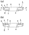
【図1】(a)第1実施例の排水目皿においてフロート弁が下降時の断面図である。(b)第1実施例の排水目皿においてフロート弁が上昇時の断面図である。
【図2】第1実施例の排水目皿を示す上面図である。
【図3】第1実施例の排水目皿を示す底面図である。
【図4】図1(a)のA−A’断面図である。
【図5】第1実施例の施工状態を示す断面図である。
【図6】(a)第2実施例の排水目皿においてフロート弁が下降時の断面図である。(b)第2実施例の排水目皿においてフロート弁が上昇時の断面図である。
【図7】図6(a)のA−A’断面図である。
【図8】他の実施例の排水目皿を示す断面図である。
【図9】他の実施例の排水目皿を示す断面図である。
【図10】他の実施例の排水目皿を示す断面図である。
【図11】他の実施例の排水目皿を示す断面図である。
【図12】(a)従来例の排水目皿においてフロート弁が下降時の断面図である。(b)従来例の排水目皿においてフロート弁が上昇時の断面図である。
【図13】(a)従来例の排水目皿においてフロート弁が下降時の断面図である。(b)従来例の排水目皿においてフロート弁が上昇時の断面図である。
【符号の説明】
1 天面部
2 開口部
3 フロート弁
4 凸溝
5 凹溝
6 ガイド部
7 鍔部
8 水密部材
9 接続口[0001]
[Industrial applications]
The present invention relates to a drainage plate used for a drainage outlet in a washbasin, a bathroom, a kitchen, and the like.
[0002]
[Prior art]
Conventionally, drainage plates described in a) and a) below are known.
A) The conventional drainage dish shown in FIG. 12 includes a top surface, an opening, and a float valve described below.
The top surface has a circular shape and is watertightly attached to the drain port of the drainage device. In addition, a guide portion vertically provided downward is provided coaxially with the top surface portion on the lower surface. Further, the guide portion constitutes a flange portion projecting in the lateral direction.
A plurality of openings are formed in the top surface.
The float valve has a circular donut shape with an opening at the center in plan view, has a specific gravity of less than 1, and is arranged to be vertically movable with the guide portion as its axis.
As a function of this drainage plate, as shown in FIG. 12A, the float valve is normally lowered by its own weight, and the lower surface of the float valve is arranged in contact with the flange portion, as shown in FIG. When water is drained from the upper surface of the top surface, the water is drained from the upper surface of the top surface to the lower surface through the opening.
Also, as shown in FIG. 12 (b), since the float valve has a specific gravity lower than 1 with respect to the backflow water from the lower surface of the top surface, the float valve floats with the backflow water, The float valve is in contact with the lower surface of the top surface. At this time, since the opening is watertightly closed by the float valve, the backflow water does not flow back to the top surface. When the backflow water is settled, the float valve descends due to its own weight and comes into contact with the flange.
A) The conventional drainage dish shown in FIG. 13 is composed of a top surface portion and an opening having the same configuration as in the above item a), and further has a float valve having the following configuration.
The float valve has a circular donut shape having an opening at the center in a plan view, has a specific gravity of less than 1, and is arranged to be vertically movable around a guide portion as its axis. On the upper surface, a convex groove is provided so as to protrude on a concentric axis, and this convex groove comes into contact with the periphery of the opening of the top surface when the float valve floats.
As shown in FIG. 13 (a), the function of this drainage plate is that the float valve is normally lowered by its own weight, and the lower surface of the float valve is arranged in contact with the flange, as shown in FIG. When water is drained from the upper surface of the top surface, the water is drained from the upper surface of the top surface to the lower surface through the opening.
Further, as shown in FIG. 13 (b), the float valve has a specific gravity lower than 1 with respect to the backflow water from the lower surface of the top surface portion, so that the float valve floats with the backflow water, The convex groove of the float valve is in contact with the periphery of the opening on the lower surface of the top surface. At this time, since the opening is watertightly closed by the convex groove of the float valve, the backflow water does not flow back to the top surface.
When the backflow water is settled, the float valve descends due to its own weight and comes into contact with the flange.
[0003]
[Patent Document 1]
JP-A-3-260230 (FIG. 1)
[Patent Document 2]
JP-A-2002-88856 (FIGS. 1 and 3)
[0004]
[Problems to be solved by the invention]
By the way, the conventional drainage plate has the following problems a) to e).
a) In the drainage dish having the above configuration a), since the contact area between the lower surface of the top surface and the float valve is large, when the float valve descends by its own weight, the float valve contacts the lower surface of the top surface due to the surface tension of water. In some cases, it was not possible to descend with its own weight while touching.
b) In order to solve the above problem a), the drainage dish of the configuration a) has a small contact area as compared with the method a) because the convex groove is provided on the upper surface of the float valve and is used as the contact surface. Thus, the problem a) is less likely to be affected by the surface tension of water. However, when the center of the float valve is eccentric with respect to the guide portion and the position is shifted, the convex groove is provided in the float valve, so that the convex groove is also eccentric, and the opening on the lower surface of the top surface portion is formed. The convex groove did not come into contact with the peripheral edge, and the water blocking surface was not formed due to, for example, the contact surface of the convex groove being disposed at the opening, and the water could not be satisfactorily stopped by the float valve.
c) In the drainage plate having the configuration of a), when the float valve is lowered, the convex groove is provided on the upper surface of the float valve, so that the drainage always stays by the height of the convex groove. . Therefore, water scale and drainage dust easily adhere to the float valve particularly near the convex groove, and even when the float valve rises, the water scale and the like intervene between the lower surface of the top surface and the convex groove and cannot stop the backflow water satisfactorily. Was.
d) Normally, when the float valve is lowered, the upper surface of the float valve into which drainage flows from the upper surface of the top surface is always exposed to drainage. At this time, the float valve is made of a soft member such as silicone rubber or foamed resin. However, there is a problem that these materials are more likely to be deteriorated than ordinary hard resin. In particular, the float valve of the above configuration a) is particularly prone to deterioration as compared with other thick portions because the contact portion is a thin convex groove. There was a problem.
[0005]
Therefore, the drainage plate of the present invention solves the following problems.
{Circle around (1)} Even if the surface tension of the drainage is generated, the float valve can descend favorably by its own weight without being disturbed by the surface tension.
{Circle over (2)} Even if the float valve is misaligned, water can be stopped well.
{Circle around (3)} It is possible to prevent the scale of the float valve from adhering and to secure a good water stoppage.
(4) It is possible to prevent the float valve from deteriorating due to drainage and secure good water stoppage.
[0006]
[Means for Solving the Problems]
The drainage plate according to the present invention includes a top surface portion (1) which is attached to a water outlet in a watertight manner, an opening portion (2) opened in the top surface portion (1), and a float for closing the opening portion (2). A drainage dish comprising a valve (3), wherein a convex groove (4) is provided in a peripheral edge of a lower surface of the opening (2).
[0007]
The drainage plate according to the present invention includes a top surface portion (1) which is attached to a water outlet in a watertight manner, an opening portion (2) opened in the top surface portion (1), and a float for closing the opening portion (2). A drainage dish comprising a valve (3), wherein a groove (5) is provided in a peripheral edge of a lower surface of the opening (2).
[0008]
In the drainage plate of the present invention, a plurality of the openings (2) are provided, and a plurality of the openings (2) are formed by the convex grooves (4) or the concave grooves (5) so as to be completely closed by the float valve (3). The drainage plate described in the paragraph [0006] or [0007], wherein the drainage plate is configured as described above.
[0009]
The drainage dish according to the present invention is characterized in that a convex groove (4) or a concave groove (5) is provided so as to surround the periphery of the opening (2). It is a drainage plate described in the above.
[0010]
The drainage plate according to the present invention includes a top surface portion (1) which is attached to a water outlet in a watertight manner, an opening portion (2) opened in the top surface portion (1), and a float for closing the opening portion (2). A drain (6) comprising a valve (3) and a guide portion (6) vertically extending downward from the top surface portion (1); A flange (7) provided, and the float valve (3) is provided so as to be vertically movable by being guided by the guide (6), and is provided with a flange from the lower surface of the top surface (1). Part (7), and the flange (7) is provided with a convex groove (4) vertically extending upward or a concave groove (5) vertically extending downward. It is a drainage dish characterized by the following.
[0011]
【Example】
Hereinafter, a first embodiment of the present invention will be described with reference to the drawings shown in FIGS.
The present invention includes a top surface (1), an opening (2), a float valve (3), and a connection port (9) described below.
The top surface portion (1) is a circular member that is attached to the drain port of the device in a water-tight manner. In this embodiment, a rubber water-tight member (8) is attached to the outer periphery of the top portion (1) so that the top surface portion (1) is attached to the drain port. The top surface (1) can be detachably and watertightly attached to the drain port. Further, the guide portion (6) is provided vertically below the top surface portion (1) in cross-section and provided at the center thereof, and has a connection port (9) described later opened therein.
At the lower end of the guide portion (6), a flange portion (7) is provided to protrude toward the side surface, and a convex groove (4) is provided on the upper surface of the flange portion (7) to protrude upward. Constitute.
The opening (2) is an opening for draining water from the upper surface of the top surface (1) to the lower surface side of the top surface (1), and a plurality of openings (2) provided radially around the guide portion (6). 2).
Further, the periphery of the opening portion (2) on the lower surface of the top surface portion (1), specifically, as shown in FIG. 4, the convex groove (4) is provided in two rows so as to be concentric with the guide portion (6). . An opening (2) is arranged between the convex grooves (4) arranged in the two rows.
The float valve (3) has a circular donut shape having an opening at the center in a plan view, and is made of a material having a specific gravity less than 1 such as foamed resin or silicone rubber and having a high specific gravity. The upper end is disposed between the convex groove (4) on the opening (2) side and the lower limit is disposed between the convex groove (4) on the flange (7) side.
[0012]
1 (a), the float valve (3) normally descends due to its own weight, and the lower surface of the float valve (3) is brought into contact with the convex groove (4) of the flange (7) as shown in FIG. It is placed in contact.
When the water is drained from the upper surface of the top surface portion (1), the water is drained from the upper surface side of the top surface portion (1) to the lower surface side through the opening (2).
Further, as shown in FIG. 1B, the float valve (3) is made of a material having a specific gravity lighter than 1 for the backflow water from the lower surface of the top surface portion (1). 3) floats with the backflow water, and the float valve (3) comes into contact with the convex groove (4) of the top surface (1).
At this time, since the opening (2) is opened in the convex groove (4), the backflow water does not flow back to the top surface (1).
Also, a convex groove (4) is provided on the upper surface of the flange (7), and the convex groove (4) is used as a contact surface with the float valve (3) when the float valve (3) is lowered. Even when the float valve (3) comes into contact with the float valve (3) and the surface tension of the drainage is generated, the contact area of the float valve (3) is reduced, so that the float valve (3) can be less affected by the surface tension. The float valve (3) can be satisfactorily raised by the backflow water without being disturbed by surface tension.
In addition, since the convex groove (4) is provided on the lower surface of the top surface portion (1) and the convex groove (4) is used as a contact surface with the float valve (3), the convex groove (4) and the float valve (3) are provided. ) Abuts and causes a surface tension of the drainage water, so that the contact area of the float valve (3) is reduced, so that the float valve (3) can be less affected by the surface tension and is not disturbed by the surface tension. The float valve (3) can descend well by its own weight.
Also, even if the float valve (3) is misaligned or eccentric with respect to the guide portion (6), the position is not shifted because the convex groove (4) is provided on the lower surface of the top surface portion (1). Of course not. Therefore, the float valve (3) comes into contact with the convex groove (4) and can stop water satisfactorily. Further, since the float valve (3) is not provided with a convex shape, water scale and waste water do not stick to the float valve (3), and the float valve (3) and the convex groove (4) come into contact with each other, so that a good stop is obtained. Aqueous is maintained.
In addition, since the drainage does not always stay on the float valve (3) and the float valve (3) has no convex thin portion, the float valve (3) is prevented from deteriorating and has good water stopping performance. Can be secured.
[0013]
In the first embodiment, the guide portion (6) has a connection port (9). As shown in FIG. 5, the connection port (9) is provided in a drain port opened in a waterproof pan in a bathroom, for example. This is an opening for watertightly connecting the drain from the bathtub to the connection port (9) of the drainage dish to drain the water from the bathtub to the pipe below the waterproof pan when the dish is attached.
[0014]
Hereinafter, a second embodiment of the present invention will be described with reference to the drawings shown in FIGS.
The present invention comprises an opening (2) having the same configuration as that of the first embodiment, a float valve (3), and a top surface (1) described below.
The top surface portion (1) is a circular member that is attached to the drain port of the device in a water-tight manner. In this embodiment, a rubber water-tight member (8) is attached to the outer periphery of the top portion (1) so that the top surface portion (1) is attached to the drain port. The top surface (1) can be detachably and watertightly attached to the drain port. Further, the guide portion (6) is provided vertically below the top surface portion (1) in cross-section and provided at the center thereof, and has a connection port (9) described later opened therein. Further, a flange (7) projecting toward the side surface is formed at the lower end of the guide (6).
Further, a concave groove (5) is formed so as to be concentric with the guide part (6), as shown in FIG. 7, in the periphery of the opening part (2) on the lower surface of the top part (1). The opening (2) is arranged in the concave groove (5).
[0015]
In operation, the float valve (3) is normally lowered by its own weight as shown in FIG. 6 (a), and the lower surface of the float valve (3) is arranged in contact with the flange (7). You.
When the water is drained from the upper surface of the top surface portion (1), the water is drained from the upper surface side of the top surface portion (1) to the lower surface side through the opening (2).
In addition, as shown in FIG. 6B, a float valve (3) having a specific gravity lower than 1 floats against the backflow water from the lower surface of the top surface portion (1). The float valve (3) is in contact with the outer edge of the concave groove (5) of the top surface (1).
At this time, the opening (2) is closed by the float valve (3) contacting the outer edge of the concave groove (5), and the backflow water does not flow back to the top surface (1).
Further, a concave groove (5) is formed in the lower surface of the top surface (1), and the outer edge of the concave groove (5) is used as a contact surface with the float valve (3). Even when the surface tension of the drainage occurs due to the contact of (3), the contact area of the float valve (3) is reduced, so that the float valve (3) can be less affected by the surface tension, and is hindered by the surface tension. Without this, the float valve (3) can descend favorably by its own weight.
Also, even if the float valve (3) is misaligned or eccentric with respect to the guide portion (6), since the concave groove (5) is recessed on the lower surface of the top surface portion (1), the misalignment can be prevented. Needless to say, the float valve (3) comes into contact with the outer edge of the concave groove (5) and can stop water well.
In addition, since the float valve (3) is not provided with a convex shape, water scale and waste water do not stick to the float valve (3), and the float valve (3) and the concave groove (5) come into contact with each other, and a good stop is obtained. Aqueous is maintained.
In addition, since the drainage does not always stay on the float valve (3) and the float valve (3) has no convex thin portion, the float valve (3) is prevented from deteriorating and has good water stopping performance. Can be secured.
[0016]
In the second embodiment, the guide portion (6) has a connection port (9). As shown in FIG. 5, the connection port (9) is provided in a drain port opened in a waterproof pan in a bathroom, for example. This is an opening for watertightly connecting the drain from the bathtub to the connection port (9) of the drainage dish to drain the water from the bathtub to the pipe below the waterproof pan when the dish is attached.
[0017]
In both the first and second embodiments, the top surface portion (1) is made of a hard resin material, and specifically, is made of an acrylonitrile / butadiene / styrene resin, an acetal resin, or a polypropylene resin. Since these resin materials have high chemical resistance and heat resistance, they can have extremely high durability without being affected by the drainage of hot water or the detergent contained in the drainage.
[0018]
Although the drainage plate of the present invention is as described above, it is not limited to the above embodiment. For example, as shown in FIG. 8, even in a drainage dish without a guide portion (6) at the center of the top surface portion (1), a convex groove (4) is formed on the periphery of the opening (2) on the lower surface of the top surface portion (1). If the concave groove (5) is formed, the drainage plate of the present invention can be implemented.
[0019]
Further, as shown in FIG. 9, the drainage plate of the present invention can be implemented even if the guide portion (6) is not provided with a connection port (9).
[0020]
As shown in FIGS. 10 and 11, the arrangement of the convex groove (4) in plan view is such that the opening (2) and the float valve (3) abut in a watertight manner, and the lower surface of the top surface (1) If the convex groove (4) is formed on the periphery of the opening (2), the drainage plate of the present invention can be implemented. The same applies to the concave groove (5).
[0021]
In the first embodiment, the convex groove (4) is formed on the upper surface of the flange portion (7). However, for example, the concave groove (5) provided on the upper surface of the flange portion (7) may be formed. The drainage plate of the invention can be implemented.
[0022]
Further, in the first embodiment or the second embodiment, the float valve (3) is described as the float valve (3) having a specific gravity lighter than 1, but the float valve (3) having a specific gravity larger than 1 is also applicable to the present invention. A drainage plate can be implemented.
[0023]
Further, in the above-described embodiment, the drainage plate when used as a drainage port in a bathroom is described. However, it may be used in, for example, a waterproof pan of a washing machine, a washbasin, and a drainage port in a kitchen.
[0024]
【The invention's effect】
According to the drainage plate of the present invention, the convex groove or the concave groove is provided on the lower peripheral edge of the opening, so that the contact area between the float valve and the lower surface of the top surface is reduced, and even if surface tension of the drainage is generated, it is obstructed. The float valve can be lowered favorably by its own weight without being operated, and there is no malfunction such that the float valve does not descend by its own weight.
Also, by providing a convex groove or a concave groove on the upper surface of the flange portion, the contact area between the float valve and the upper surface of the flange portion is reduced, so that even if surface tension of drainage occurs, the float valve can be operated without being disturbed by it. The water can be satisfactorily raised by the backflow water and there is no malfunction such that the float valve does not rise by the backflow water.
In addition, since the convex groove and the concave groove are provided on the peripheral edge of the lower surface of the opening, it is possible to satisfactorily stop water even if the float valve is misaligned.
In addition, since the convex groove and the concave groove are provided on the peripheral edge of the lower surface of the opening, it is possible to prevent scales and the like from adhering to the float valve and to secure good water stoppage.
Further, by providing the convex groove and the concave groove on the lower peripheral edge of the opening, deterioration of the float valve due to drainage can be prevented more than in the configuration of the conventional example a), and good water stoppage can be secured.
[Brief description of the drawings]
FIG. 1A is a cross-sectional view of a drainage dish according to a first embodiment when a float valve is lowered. (B) It is sectional drawing at the time of a float valve rising in the drainage dish of 1st Example.
FIG. 2 is a top view showing the drainage dish of the first embodiment.
FIG. 3 is a bottom view showing the drainage dish of the first embodiment.
FIG. 4 is a sectional view taken along line AA ′ of FIG.
FIG. 5 is a sectional view showing a construction state of the first embodiment.
FIG. 6A is a cross-sectional view of the drainage dish according to the second embodiment when the float valve is lowered. (B) It is sectional drawing at the time of a float valve rising in the drainage dish of 2nd Example.
FIG. 7 is a sectional view taken along the line AA ′ of FIG.
FIG. 8 is a sectional view showing a drainage dish according to another embodiment.
FIG. 9 is a sectional view showing a drainage dish according to another embodiment.
FIG. 10 is a sectional view showing a drainage dish according to another embodiment.
FIG. 11 is a sectional view showing a drainage dish according to another embodiment.
FIG. 12A is a cross-sectional view of a conventional drainage dish when the float valve is lowered. (B) It is sectional drawing at the time of a float valve rising in the drainage plate of the prior art example.
FIG. 13A is a cross-sectional view of a conventional drainage dish when the float valve is lowered. (B) It is sectional drawing at the time of a float valve rising in the drainage plate of the prior art example.
[Explanation of symbols]
DESCRIPTION OF
Claims (5)
該天面部(1)に開口された開口部(2)と、
該開口部(2)を閉塞するフロート弁(3)と、
から構成される排水目皿において、
前記開口部(2)の下面周縁に凸溝(4)を設けたことを特徴とする排水目皿。A top part (1) that is attached watertight to the drain,
An opening (2) opened in the top surface (1),
A float valve (3) for closing the opening (2);
In the drainage plate composed of
A drainage dish characterized in that a convex groove (4) is provided in a peripheral edge of a lower surface of the opening (2).
該天面部(1)に開口された開口部(2)と、
該開口部(2)を閉塞するフロート弁(3)と、
から構成される排水目皿において、
前記開口部(2)の下面周縁に凹溝(5)を設けたことを特徴とする排水目皿。A top part (1) that is attached watertight to the drain,
An opening (2) opened in the top surface (1),
A float valve (3) for closing the opening (2);
In the drainage plate composed of
A drainage dish provided with a concave groove (5) in a peripheral edge of a lower surface of the opening (2).
該天面部(1)に開口された開口部(2)と、
該開口部(2)を閉塞するフロート弁(3)と、
から構成される排水目皿において、
前記天面部(1)に対して下方に垂設されるガイド部(6)と、
ガイド部(6)下端に側面方向に向かって凸設される鍔部(7)と、を構成すると共に、
前記フロート弁(3)を、前記ガイド部(6)によりガイドされて上下動自在に備えられ、且つ前記天面部(1)下面から鍔部(7)の間に配置させ、前記鍔部(7)に、上方に向かって垂設される凸溝(4)又は下方に向かって垂設される凹溝(5)を設けたことを特徴とする排水目皿。A top part (1) that is attached watertight to the drain,
An opening (2) opened in the top surface (1),
A float valve (3) for closing the opening (2);
In the drainage plate composed of
A guide portion (6) vertically suspended from the top surface portion (1);
A guide portion (6) and a flange portion (7) projecting toward the side at the lower end, and
The float valve (3) is provided so as to be vertically movable while being guided by the guide portion (6), and is disposed between the lower surface of the top surface portion (1) and the flange portion (7). ) Is provided with a convex groove (4) vertically extending upward or a concave groove (5) vertically extending downward.
Priority Applications (1)
| Application Number | Priority Date | Filing Date | Title |
|---|---|---|---|
| JP2003071677A JP4517055B2 (en) | 2003-03-17 | 2003-03-17 | Draining eye plate |
Applications Claiming Priority (1)
| Application Number | Priority Date | Filing Date | Title |
|---|---|---|---|
| JP2003071677A JP4517055B2 (en) | 2003-03-17 | 2003-03-17 | Draining eye plate |
Publications (2)
| Publication Number | Publication Date |
|---|---|
| JP2004278140A true JP2004278140A (en) | 2004-10-07 |
| JP4517055B2 JP4517055B2 (en) | 2010-08-04 |
Family
ID=33288054
Family Applications (1)
| Application Number | Title | Priority Date | Filing Date |
|---|---|---|---|
| JP2003071677A Expired - Lifetime JP4517055B2 (en) | 2003-03-17 | 2003-03-17 | Draining eye plate |
Country Status (1)
| Country | Link |
|---|---|
| JP (1) | JP4517055B2 (en) |
Citations (6)
| Publication number | Priority date | Publication date | Assignee | Title |
|---|---|---|---|---|
| JPH03260230A (en) * | 1990-03-09 | 1991-11-20 | Matsushita Electric Ind Co Ltd | Drainer for unit bath |
| JP2001200565A (en) * | 1999-11-12 | 2001-07-27 | Yasumi Ota | Drainage trap |
| JP2002088856A (en) * | 2000-09-21 | 2002-03-27 | Inax Corp | Perforated plate for floor drain of bathroom |
| JP2004169439A (en) * | 2002-11-21 | 2004-06-17 | Yamaha Livingtec Corp | Waste-water float structure |
| JP2004225413A (en) * | 2003-01-24 | 2004-08-12 | Yamaha Livingtec Corp | Drain float structure |
| JP2004238896A (en) * | 2003-02-05 | 2004-08-26 | Yamaha Livingtec Corp | Drain float structure |
-
2003
- 2003-03-17 JP JP2003071677A patent/JP4517055B2/en not_active Expired - Lifetime
Patent Citations (6)
| Publication number | Priority date | Publication date | Assignee | Title |
|---|---|---|---|---|
| JPH03260230A (en) * | 1990-03-09 | 1991-11-20 | Matsushita Electric Ind Co Ltd | Drainer for unit bath |
| JP2001200565A (en) * | 1999-11-12 | 2001-07-27 | Yasumi Ota | Drainage trap |
| JP2002088856A (en) * | 2000-09-21 | 2002-03-27 | Inax Corp | Perforated plate for floor drain of bathroom |
| JP2004169439A (en) * | 2002-11-21 | 2004-06-17 | Yamaha Livingtec Corp | Waste-water float structure |
| JP2004225413A (en) * | 2003-01-24 | 2004-08-12 | Yamaha Livingtec Corp | Drain float structure |
| JP2004238896A (en) * | 2003-02-05 | 2004-08-26 | Yamaha Livingtec Corp | Drain float structure |
Also Published As
| Publication number | Publication date |
|---|---|
| JP4517055B2 (en) | 2010-08-04 |
Similar Documents
| Publication | Publication Date | Title |
|---|---|---|
| KR101493605B1 (en) | Drain device | |
| JP2004278140A (en) | Drainage perforated plate | |
| JP5748419B2 (en) | Drainage equipment | |
| JP3856120B2 (en) | Bathroom unit drain trap | |
| CN212001430U (en) | Easily clean bounce hydrophone and bathroom subassembly down | |
| JP3879743B2 (en) | Drain trap | |
| WO2014079331A1 (en) | Anti-dipping toilet pan | |
| JP4512687B2 (en) | Slime drain cover | |
| JP6443959B1 (en) | Washbasin | |
| JP4374411B2 (en) | Draining eye plate | |
| JP4277083B2 (en) | Drainage equipment | |
| JP4388441B2 (en) | Bathroom drain piping | |
| JP2520159Y2 (en) | Bathroom drain | |
| JPS6013906Y2 (en) | Perforated plate for drainage equipment | |
| CN220789975U (en) | Anti-overflow water structure and integrated water tank | |
| JPH03260230A (en) | Drainer for unit bath | |
| JP6060327B2 (en) | Drain trap | |
| JP2003082736A (en) | Drain device | |
| JP7276735B2 (en) | Drainage device | |
| JP2007177542A (en) | Hair catcher | |
| JP2004238896A (en) | Drain float structure | |
| JP2021173137A (en) | Hair catcher | |
| JP2017029358A (en) | Wash stand | |
| JP5270881B2 (en) | Hair catcher | |
| JP4872045B2 (en) | Bathroom drainage equipment |
Legal Events
| Date | Code | Title | Description |
|---|---|---|---|
| A621 | Written request for application examination |
Free format text: JAPANESE INTERMEDIATE CODE: A621 Effective date: 20060307 |
|
| A521 | Request for written amendment filed |
Free format text: JAPANESE INTERMEDIATE CODE: A821 Effective date: 20060310 |
|
| A977 | Report on retrieval |
Free format text: JAPANESE INTERMEDIATE CODE: A971007 Effective date: 20071001 |
|
| A131 | Notification of reasons for refusal |
Free format text: JAPANESE INTERMEDIATE CODE: A131 Effective date: 20090310 |
|
| A521 | Request for written amendment filed |
Free format text: JAPANESE INTERMEDIATE CODE: A523 Effective date: 20090511 |
|
| A521 | Request for written amendment filed |
Free format text: JAPANESE INTERMEDIATE CODE: A523 Effective date: 20090603 |
|
| A02 | Decision of refusal |
Free format text: JAPANESE INTERMEDIATE CODE: A02 Effective date: 20091110 |
|
| A521 | Request for written amendment filed |
Free format text: JAPANESE INTERMEDIATE CODE: A523 Effective date: 20100128 |
|
| A911 | Transfer to examiner for re-examination before appeal (zenchi) |
Free format text: JAPANESE INTERMEDIATE CODE: A911 Effective date: 20100217 |
|
| TRDD | Decision of grant or rejection written | ||
| A01 | Written decision to grant a patent or to grant a registration (utility model) |
Free format text: JAPANESE INTERMEDIATE CODE: A01 Effective date: 20100316 |
|
| A01 | Written decision to grant a patent or to grant a registration (utility model) |
Free format text: JAPANESE INTERMEDIATE CODE: A01 |
|
| A61 | First payment of annual fees (during grant procedure) |
Free format text: JAPANESE INTERMEDIATE CODE: A61 Effective date: 20100323 |
|
| FPAY | Renewal fee payment (event date is renewal date of database) |
Free format text: PAYMENT UNTIL: 20130528 Year of fee payment: 3 |
|
| R150 | Certificate of patent or registration of utility model |
Free format text: JAPANESE INTERMEDIATE CODE: R150 Ref document number: 4517055 Country of ref document: JP Free format text: JAPANESE INTERMEDIATE CODE: R150 |
|
| FPAY | Renewal fee payment (event date is renewal date of database) |
Free format text: PAYMENT UNTIL: 20130528 Year of fee payment: 3 |
|
| S531 | Written request for registration of change of domicile |
Free format text: JAPANESE INTERMEDIATE CODE: R313531 |
|
| FPAY | Renewal fee payment (event date is renewal date of database) |
Free format text: PAYMENT UNTIL: 20130528 Year of fee payment: 3 |
|
| R350 | Written notification of registration of transfer |
Free format text: JAPANESE INTERMEDIATE CODE: R350 |
|
| FPAY | Renewal fee payment (event date is renewal date of database) |
Free format text: PAYMENT UNTIL: 20130528 Year of fee payment: 3 |
|
| R250 | Receipt of annual fees |
Free format text: JAPANESE INTERMEDIATE CODE: R250 |
|
| R250 | Receipt of annual fees |
Free format text: JAPANESE INTERMEDIATE CODE: R250 |
|
| R250 | Receipt of annual fees |
Free format text: JAPANESE INTERMEDIATE CODE: R250 |
|
| R250 | Receipt of annual fees |
Free format text: JAPANESE INTERMEDIATE CODE: R250 |
|
| EXPY | Cancellation because of completion of term |