JP2004268564A - Assembly equipped with blanket unit and cylinder having blanket unit fixing device, and corresponding cylinder, blanket unit and offset printing machine - Google Patents
Assembly equipped with blanket unit and cylinder having blanket unit fixing device, and corresponding cylinder, blanket unit and offset printing machine Download PDFInfo
- Publication number
- JP2004268564A JP2004268564A JP2003326896A JP2003326896A JP2004268564A JP 2004268564 A JP2004268564 A JP 2004268564A JP 2003326896 A JP2003326896 A JP 2003326896A JP 2003326896 A JP2003326896 A JP 2003326896A JP 2004268564 A JP2004268564 A JP 2004268564A
- Authority
- JP
- Japan
- Prior art keywords
- blanket
- support plate
- opening
- cylinder
- front edge
- Prior art date
- Legal status (The legal status is an assumption and is not a legal conclusion. Google has not performed a legal analysis and makes no representation as to the accuracy of the status listed.)
- Granted
Links
- 238000007645 offset printing Methods 0.000 title claims abstract description 14
- 230000002093 peripheral effect Effects 0.000 claims description 10
- 238000000034 method Methods 0.000 claims description 7
- 238000003825 pressing Methods 0.000 claims description 7
- 230000007246 mechanism Effects 0.000 description 10
- 238000007639 printing Methods 0.000 description 3
- 238000011144 upstream manufacturing Methods 0.000 description 3
- 230000001154 acute effect Effects 0.000 description 2
- 238000005452 bending Methods 0.000 description 2
- 238000007373 indentation Methods 0.000 description 2
- 230000007935 neutral effect Effects 0.000 description 2
- 230000006978 adaptation Effects 0.000 description 1
- 238000004026 adhesive bonding Methods 0.000 description 1
- 230000000712 assembly Effects 0.000 description 1
- 238000000429 assembly Methods 0.000 description 1
- 229920001971 elastomer Polymers 0.000 description 1
- 239000000806 elastomer Substances 0.000 description 1
- 239000004744 fabric Substances 0.000 description 1
- 238000004519 manufacturing process Methods 0.000 description 1
- 239000002184 metal Substances 0.000 description 1
- 230000035939 shock Effects 0.000 description 1
- 229910001220 stainless steel Inorganic materials 0.000 description 1
- 239000010935 stainless steel Substances 0.000 description 1
- 238000004073 vulcanization Methods 0.000 description 1
Images


Classifications
-
- B—PERFORMING OPERATIONS; TRANSPORTING
- B41—PRINTING; LINING MACHINES; TYPEWRITERS; STAMPS
- B41F—PRINTING MACHINES OR PRESSES
- B41F27/00—Devices for attaching printing elements or formes to supports
- B41F27/12—Devices for attaching printing elements or formes to supports for attaching flexible printing formes
- B41F27/1218—Devices for attaching printing elements or formes to supports for attaching flexible printing formes comprising printing plate tensioning devices
- B41F27/1225—Devices for attaching printing elements or formes to supports for attaching flexible printing formes comprising printing plate tensioning devices moving in the printing plate end substantially rectilinearly
- B41F27/1243—Devices for attaching printing elements or formes to supports for attaching flexible printing formes comprising printing plate tensioning devices moving in the printing plate end substantially rectilinearly by pivotal or swivelling motion, e.g. by means of a rocking lever
-
- B—PERFORMING OPERATIONS; TRANSPORTING
- B41—PRINTING; LINING MACHINES; TYPEWRITERS; STAMPS
- B41F—PRINTING MACHINES OR PRESSES
- B41F27/00—Devices for attaching printing elements or formes to supports
- B41F27/12—Devices for attaching printing elements or formes to supports for attaching flexible printing formes
- B41F27/1218—Devices for attaching printing elements or formes to supports for attaching flexible printing formes comprising printing plate tensioning devices
- B41F27/125—Devices for attaching printing elements or formes to supports for attaching flexible printing formes comprising printing plate tensioning devices moving in the printing plate end on a curvilinear path, e.g. by winding on a roll
-
- B—PERFORMING OPERATIONS; TRANSPORTING
- B41—PRINTING; LINING MACHINES; TYPEWRITERS; STAMPS
- B41F—PRINTING MACHINES OR PRESSES
- B41F30/00—Devices for attaching coverings or make-ready devices; Guiding devices for coverings
- B41F30/04—Devices for attaching coverings or make-ready devices; Guiding devices for coverings attaching to transfer cylinders
Landscapes
- Engineering & Computer Science (AREA)
- Mechanical Engineering (AREA)
- Printing Plates And Materials Therefor (AREA)
- Rotary Presses (AREA)
- Supply, Installation And Extraction Of Printed Sheets Or Plates (AREA)
Abstract
Description
本発明は、
ブランケットおよびブランケットサポートプレートを備えたブランケットユニットであって、ブランケットサポートプレートのフロントエッジおよびリアエッジが、それぞれフロントベンドの領域およびリアベンドの領域で曲がり、ブランケットサポートプレートのリアエッジが、ブランケットの、リアベンドに隣接して位置付けされたリアエッジを越えて突出したブランケットユニットと、
ブランケットサポートプレートのフロントエッジおよびリアエッジを受け入れるための開口を有するシリンダであって、ブランケットユニットを引っ張るための、ブランケットサポートプレートのリアエッジの開口中への受け入れるように構成された少なくとも1つのフックを備えた、ブランケットユニットをシリンダに固定するための固定装置を備え、ブランケットサポートプレートのリアエッジに実質的に平行な引張り荷重をブランケットサポートプレートに印加するべく、開口中にリアエッジが挿入されるシリンダと、を備えたタイプのオフセット印刷機用アセンブリに関する。
The present invention
A blanket unit comprising a blanket and a blanket support plate, wherein a front edge and a rear edge of the blanket support plate are bent in a front bend area and a rear bend area, respectively, and a rear edge of the blanket support plate is adjacent to the blanket, the rear bend. A blanket unit protruding beyond the rear edge
A cylinder having an opening for receiving a front edge and a rear edge of a blanket support plate, the cylinder having at least one hook configured to receive into the opening of the rear edge of the blanket support plate for pulling a blanket unit. A securing device for securing the blanket unit to the cylinder, wherein the rear edge is inserted into the opening to apply a tensile load to the blanket support plate substantially parallel to the rear edge of the blanket support plate. Assembly for offset printing presses.
従来、この種の印刷機は、ブランケット搬送シリンダおよびブランケット以外に、プレート搬送シリンダ、プレートおよび圧搾シリンダを備えている。 2. Description of the Related Art Conventionally, this type of printing press includes a plate transport cylinder, a plate, and a pressing cylinder in addition to a blanket transport cylinder and a blanket.
動作中、プレート搬送シリンダによって搬送されたプレートに湿気が加えられ、続いてインキが施される。プレートによって、プレートの印刷領域からブランケット搬送シリンダによって搬送されたブランケットにインキが引き渡され、次に、ブランケットによって、ブランケット搬送シリンダと圧搾シリンダの間を通過する印刷すべき用紙にインキが引き渡される。 In operation, moisture is applied to the plate transported by the plate transport cylinder, followed by ink application. The plate delivers ink from the printing area of the plate to the blanket transported by the blanket transport cylinder, which in turn delivers the ink to the paper to be printed passing between the blanket transport cylinder and the squeezing cylinder.
シリンダ上のブランケットを引っ張るために、ブランケットの両端にクリンプされた金属バーが伝統的に使用されている。これらのバーは、シリンダの開口中で係合し、ねじ式の装置によって押し付けられている。 Metal bars crimped at both ends of the blanket are traditionally used to pull the blanket on the cylinder. These bars engage in the opening of the cylinder and are pressed by a screw-type device.
このような構造は、22mmに及ぶ極めて広い開口幅をもたらしている。 Such a structure results in an extremely wide opening width of up to 22 mm.
このような大型開口の存在は、ブランケット搬送シリンダが回転する際のプレート搬送シリンダおよび圧搾シリンダに対する衝撃および振動の原因になっている。このような振動により、さまざまなシリンダの回転速度が制限され、ひいてはオフセット印刷機の製造容量が制限されている。 The presence of such large openings causes shock and vibration on the plate transport cylinder and the squeeze cylinder when the blanket transport cylinder rotates. Such vibrations limit the rotational speeds of the various cylinders and thus the production capacity of the offset printing press.
従来技術文献は、上で言及したタイプのアセンブリを提案した。ブランケットのフロントエッジがブランケットサポートプレートのすべてのフロントエッジを覆っており、したがってブランケットのフロントエッジは、シリンダの開口中に延びている。ブランケットのリアエッジは開口中に延びずに、実質的にブランケットユニットのフロントベンド領域に当て付けられている。この方法の場合、シリンダ内に存在する開口による振動を制限するために、ブランケットの始まりとブランケットの終わりとの間の隙間が極端に狭くなっている(例えば、特許文献1参照)。
しかしながら、所望の構成をこのドキュメントに従って得るためには、プレートのフロントエッジおよびブランケットのフロントエッジを曲げることが極端に困難であることが分かっている。 However, it has been found that bending the front edge of the plate and the front edge of the blanket is extremely difficult to obtain the desired configuration according to this document.
別の従来技術文献は、ブランケットユニットを固定するための装置が、ブランケットサポートプレートのフロントエッジおよびリアエッジを開口のフロントウォールに当て付ける圧搾スタッドを備えた他の解決法を提供している。ブランケットサポートプレートのこれらのフロントエッジおよびリアエッジは、ブランケットに覆われていない。スタッドによって印加される力は、ブランケットサポートプレートのフロントエッジおよびリアエッジに対して排他的に直角をなしている(例えば、特許文献2参照)。
この構造の場合、ブランケットユニットを十分に引っ張ることができないことが分かっている。また、上で説明した固定装置は、オフセット印刷機を運転することによって生じるブランケットユニットの変形を吸収することができない。詳細には、ブランケットサポートプレートの膨張を吸収することができないため、ブランケットサポートプレートのリアベンドに隣接するプレートにクラックが発生している。 It has been found that in this configuration, the blanket unit cannot be pulled sufficiently. Moreover, the fixing device described above cannot absorb the deformation of the blanket unit caused by operating the offset printing press. Specifically, the expansion of the blanket support plate cannot be absorbed, so that a crack is generated in the plate adjacent to the rear bend of the blanket support plate.
また別の従来技術文献では、圧搾スタッドが1つまたは複数の弾発性ブレードに置換されているが、この構造の場合も、ブランケットユニットを十分に引っ張ることができない(例えば、特許文献3参照)。
本発明の目的は、上で言及したタイプの、満足すべき方法でブランケットユニットを引っ張り、かつ、シリンダに固定することができる、単純かつ経済的に製造することができるアセンブリを提供することである。 It is an object of the present invention to provide a simple and economically manufacturable assembly of the type mentioned above, in which the blanket unit can be pulled in a satisfactory manner and fixed to the cylinder. .
この目的を達成するべく、本発明は、上で言及したタイプの、ブランケットサポートプレートのフロントエッジが、フロントベンドに隣接して位置付けされたブランケットのフロントエッジを越えて突出していることを特徴とするアセンブリに関している。 To this end, the invention is characterized in that the front edge of the blanket support plate of the type mentioned above protrudes beyond the front edge of the blanket positioned adjacent the front bend. Related to assembly.
本発明の特定の実施形態によれば、アセンブリは、以下に列記する特徴の1つまたは複数をそれぞれ個別に、あるいは技術的に可能なすべての組合せに基づいて備えている。
ブランケットサポートプレートのフロントエッジと共にゼロではない角度を形成しているブランケットサポートプレートのリアエッジの領域に開口が設けられている。
フックが弾発性ブレードからなっている。
アセンブリは、ブランケットサポートプレートのフロントエッジを開口のフロントウォールに当て付けるための、フックから分離された当付け手段を備えている。
当付け手段は、ブランケットサポートプレートのフロントエッジを押し付けるための、固定装置に付属し、かつ、ブランケットサポートプレートから分離された少なくとも1つの圧搾エレメントを備えている。
圧搾エレメントは、ブランケットサポートプレートのフロントエッジを押し付けるべく、フックを受け入れる開口を通って延びている。
圧搾エレメントは、弾発性ブレードからなっている。
ブランケットサポートプレートのリアエッジが、自身、中間ベンドの領域で曲がって端部領域を画定し、該端部領域に、フックを受け入れるための開口が設けられ、中間領域は、ブランケットサポートプレートのフロントエッジへ押し付けられるように構成され、それにより当付け手段を形成している。
開口は、シリンダの周囲表面の近傍に、1.5mm未満の幅を有している。
開口の幅は、1.1mm未満である。
開口のフロントウォールおよびリアウォールが、シリンダの周囲表面を起点とする20°未満の角度を形成している。
According to a particular embodiment of the invention, the assembly comprises one or more of the features listed below, each individually or based on all technically possible combinations.
An opening is provided in the region of the rear edge of the blanket support plate that forms a non-zero angle with the front edge of the blanket support plate.
The hook consists of a resilient blade.
The assembly includes an abutment means separate from the hook for applying the front edge of the blanket support plate to the front wall of the opening.
The applying means comprises at least one squeezing element attached to the fixing device and pressed away from the blanket support plate for pressing the front edge of the blanket support plate.
The squeezing element extends through an opening for receiving a hook to press against the front edge of the blanket support plate.
The squeezing element consists of a resilient blade.
The rear edge of the blanket support plate bends itself in the region of the intermediate bend to define an end region, wherein the end region is provided with an opening for receiving a hook, the intermediate region extending to the front edge of the blanket support plate. It is configured to be pressed against, thereby forming the application means.
The opening has a width of less than 1.5 mm near the peripheral surface of the cylinder.
The width of the opening is less than 1.1 mm.
The front and rear walls of the opening form an angle of less than 20 ° starting from the peripheral surface of the cylinder.
また、本発明は、上で定義したアセンブリのためのシリンダに関している。 The invention also relates to a cylinder for the assembly as defined above.
本発明の一変形態様によれば、固定装置は、ブランケットサポートプレートのフロントエッジを開口のフロントウォールに当て付けるべく、ブランケットサポートプレートのフロントエッジを押し付けるための、フックから分離された少なくとも1つの圧搾エレメントを備えている。 According to one variant of the invention, the fixing device comprises at least one squeezed, separate from the hook, for pressing the front edge of the blanket support plate to press the front edge of the blanket support plate against the front wall of the opening. It has an element.
本発明は、さらに、上で定義したアセンブリのためのブランケットユニットに関している。 The invention further relates to a blanket unit for the assembly as defined above.
本発明の一変形態様によれば、ブランケットサポートプレートのリアエッジは、自身、中間ベンドの領域で曲がって端部領域を画定し、該端部領域に、フックを受け入れるための開口が設けられ、中間領域は、ブランケットサポートプレートのフロントエッジを開口のフロントウォールに当て付けるべく、ブランケットサポートプレートのフロントエッジへ押し付けるように構成されている。 According to a variant of the invention, the rear edge of the blanket support plate bends itself in the region of the intermediate bend to define an end region in which an opening for receiving a hook is provided, The region is configured to press against the front edge of the blanket support plate to apply the front edge of the blanket support plate to the front wall of the opening.
また、本発明は、上で定義したアセンブリを備えたオフセット印刷機に関している。 The invention also relates to an offset printing press with an assembly as defined above.
本発明は、添付の図面を参照した単なる例示として与えられた以下の説明からより良く理解される。 The invention will be better understood from the following description, given solely by way of example, with reference to the accompanying drawings, in which:
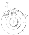
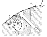
図1は、シリンダ2およびシリンダ2の周囲表面4を覆い、かつ、シリンダ2に支えられたブランケットユニット3を備えた、オフセット印刷機用アセンブリ1を略図で示したものである。
FIG. 1 schematically shows an
シリンダ2は長手方向軸線Aに沿って延び、図1では一方のみしか見えないが、シリンダ2の長手方向の両端5は、オフセット印刷機のサポート構造のベアリング中への受け入れられるように構成されている。この方法によれば、シリンダ2は、図には示されていないが従来の駆動手段を使用して、長手方向軸線Aの周りを図1の矢印6で示す方向に回転させることができる。
The
以下、使用されている「フロント」および「リア」という用語は、回転方向6を基準にして理解されたい。
Hereinafter, the terms “front” and “rear” used will be understood with reference to the direction of
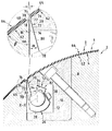
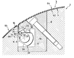
図2に示すように、シリンダ2の周囲表面4からシリンダ2内に向かって長手方向凹所8が設けられている。この凹所8は、断面が実質的に正不等辺四辺形の形をしており、シリンダ2の周囲表面4の一部に対応する側が円形になっている。
As shown in FIG. 2, a
凹所8にはインサート10がねじ込まれている。
Insert 10 is screwed into
このインサート10は、実質的に長方形の断面を有する長手方向空胴12および実質的に三角形の断面を有する長手方向開口14をシリンダ2の内部に画定している。
The
開口14は、シリンダ2の周囲表面4および空胴12に向かって開いている。
The
図2の拡大円部分に極めて詳細に示すように、開口14および空胴12に共通のフロントウォール16は、幅がたとえば約1mmの面取り部分18によって周囲表面4に接続されている。
As shown in greater detail in the enlarged circle of FIG. 2, the
同様に、開口14のリアウォール20も、面取り部分22によって周囲表面4に接続されている。この面取り部分22の幅は、たとえば約1.4mmである。
Similarly, the
開口14のフロントウォール16およびリアウォール20は、空胴12に向かって、つまり、開口14の上流側ポイントから下流側ポイントへ向かって広がっている。したがってフロントウォール16およびリアウォール20は、典型的には約14.8°である角度αをそれらの間に形成している。より一般的には、この角度αは20°未満である。
The
フロントウォール16とリアウォール20の間の開口14の上流側の幅l、すなわち面取り部分18および22の下流側の幅lは約1mmである。より一般的には、この幅lは1.5mm未満であり、1.1mm未満であることが好ましい。
The width l on the upstream side of the
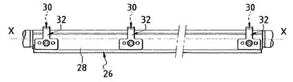
シリンダ2は、ブランケットユニット3をシリンダ2に固定するための装置26を備えている。この装置26は空胴12内に配列され、シリンダ2の軸線Aに実質的に平行な軸線X−Xに沿って延びたスピンドル28を備えている。このスピンドル28は、たとえばシリンダ2の全長さに沿って延びている。
The
図2および3に示すように、フック30および圧搾エレメント32は、スピンドル28に沿って配分されている。
As shown in FIGS. 2 and 3, hooks 30 and squeezing
フック30は弾発性ブレードによって形成され、その自由端34は、開口14に対向して湾曲している。
The
同様に、圧搾エレメント32も弾発性ブレードによって形成され、その自由端36は180°曲げられている。
Similarly, the squeezing
フック30および圧搾エレメント32は、それぞれ対の関係で結合されており、結合したフック30および圧搾エレメント32が、共通のねじ38によってスピンドル28に固定されている。圧搾エレメント32は、協働するフック30の上側に配列されている。
The
フック30および圧搾エレメント32からなる複数の対は、互いに長手方向に間隔を隔てており、スピンドル28に沿って配分されている。
A plurality of pairs of
スピンドル28は、たとえば、スピンドル28の両端および随意にはその中間領域に設けられたベアリングによって、空胴12内をスピンドル28の長手方向軸線X−Xの周りに回転することができるように取り付けられている。
The
この方法によれば、図2および図6のそれぞれに示す2つの位置の間でスピンドル28を移動させることができる。
According to this method, the
図2に示す位置、すなわちブランケットユニット3が開放される位置では、フック30および圧搾エレメント32は、開口14から離れた位置に移動し、空胴12へのアクセスを自由にしている。
In the position shown in FIG. 2, i.e. the position in which the
図6に示す位置、すなわちブランケットユニット3が固定される位置では、フック30および圧搾エレメント32は、フロントウォール16に向けて移動される。
In the position shown in FIG. 6, that is, the position where the
図2に示す位置から図6に示す位置へ移動するべく、スピンドル28は、これらの図から分かるように反時計方向に枢動する。この枢動回転は、駆動機構42によってもたらされている。図1には一方の駆動機構42しか示されていないが、シリンダ2のもう一方の側には、同様の構造を有するもう一方の駆動機構42が配置されている。したがって、以下、図1に示す駆動機構42についてのみ説明する。
To move from the position shown in FIG. 2 to the position shown in FIG. 6, the
駆動機構42は、たとえば、
シリンダのフランクに固定されたサポート44と、
カラー48を備え、かつ、スプリング50に取り囲まれたロッド46と、
スピンドル28の対応する長手方向端部54に固定されたブロック52と、
図1に一点鎖線で示す移動可能動作レバー56と、を備えている。
The
A
A
A
And a
ロッド46の第1の端部は、ブロック52に関節連結されている。ロッド46のもう一方の端部は、シリンダ2の軸線Aに対して直角をなす平面内での枢動を可能にする関節連結手段によってサポート44中に取り付けられている。スプリング50は、一方で、サポート44を押し付け、他方で、カラー48を押し付けている。
A first end of
レバー56により、ロッド46をサポート44に対して2つの安定端位置の間で移動させることができる。
The
図1は、第1の安定端位置を示している。この位置は、図2に示す、スピンドル28の開放位置に対応している。
FIG. 1 shows the first stable end position. This position corresponds to the open position of the
図7は、第2の安定端位置を示している。この位置では、スピンドル28は、図6に示す固定位置にある。
FIG. 7 shows the second stable end position. In this position, the
図1の位置から図7の位置へ移動させるためには、操作者は、図1の矢印60で示すように、レバー56を反時計方向に枢動させることになる。
To move from the position of FIG. 1 to the position of FIG. 7, the operator will pivot the
レバー56を反時計方向にピボットさせることにより、ロッド46が、ロッド46の軸線とスピンドル28の軸線X−Xが交差する不安定な中立位置を通過して移動し、それによりスプリング50が押し縮められ、ロッド46をその第2の安定位置、すなわち図7の位置に向けて復帰することになる。レバー56が図1の位置から図7の位置に移動すると、ブロック52が、スピンドル28の角度位置をその固定位置に調整することができる調整可能ストップ58に押し付けられる。
By pivoting the
この方法によれば、中立位置を通過させるための機構42により、スピンドル28をその開放位置から固定位置へ向けて、また、固定位置から開放位置へ向けて手動で変位させることができるが、何れか他のタイプの駆動機構42を使用することも可能であることに留意されたい。
According to this method, the
もう一度図2を参照すると、ブランケットユニット3が、サポートプレート62およびサポートプレート62に固定されたブランケット64を備えていることが理解されよう。
Referring again to FIG. 2, it can be seen that the
サポートプレート62は、たとえばステンレス鋼でできており、その厚さは約0.2mmである。
The
ブランケット64は、従来、たとえば複数のエラストマー層および織物層を備えている。ブランケット64は、粘着性ボンディングまたは加硫によってサポートプレート62に固定されている。
The
サポートプレート62のフロントエッジ66は、ブランケット64のフロントエッジ68を越えて延びている。サポートプレート62のフロントエッジ66は、サポートプレート62の残りの部分と鋭角βを形成するべく、フロントベンド70の領域で曲がっている。
The
ブランケット64のフロントエッジ68は、ベンド70に対してわずかに凹んだ位置に配置されているが、変形態様の中には、ベンド70を少なくとも部分的に覆うべく、フロントエッジ68が突出した位置に配置されているものもある。その場合、フロントエッジ68は、開口14中に延びないようにするために、ベンド70に隣接して配置されることになる。
The
サポートプレート62のフロントエッジ66は、ブランケット64に覆われず、開口14中に挿入されている。フロントベンド70は、面取り部分18を越えて延び、また、サポートプレート62のフロントエッジ66は、開口14のフロントウォール16に沿って延びている。
The
ブランケットユニット3の後部の形状構成は、サポートプレート62のリアエッジ72の形状構成と類似しており、該リアエッジ72は、ブランケット64のリアエッジ74に覆われていない。リアエッジ72は、サポートプレート62の残りの部分に対して、リアベンド76の領域で曲がっており、ブランケットユニット3のフロント部分の鋭角とは相異して鈍角を形成している。
The configuration of the rear of the
剥き出しのリアエッジ72は開口14に挿入され、開口14に沿って延び、かつ、開口14のリアウォール20にもたれ掛かっている。
The exposed
ブランケット64のリアエッジ74は、開口14中に延びないよう、また、ブランケット64のフロントエッジ68の比較的近傍に位置するよう、リアベンド22に隣接して配置されている。
The
サポートプレート62のフロントエッジ66およびリアエッジ72は、開口14の内部を空胴12までの延び、相伴ってゼロではない角度を形成している。
The
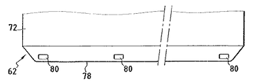
図4に示すように、サポートプレート62のリアエッジ72の自由端78には、一連の開口80が自由端78に沿って配分されている。これらの開口80は、実質的に長方形の形をしており、それぞれ、フック30および圧搾エレメント32からなる対と対向して配置されている。
At the
ブランケットユニット3をシリンダ2上に取り付けるための手順は、たとえば次の通りである。
The procedure for mounting the
スピンドル28の開放位置において、先ず、サポートプレート62のフロントエッジ66が開口14中に挿入され、次に、ブランケットユニット3が、サポートプレート62のリアエッジ72が開口14中で係合するまでシリンダ2の周囲に巻き付けられる。この時、ブランケットユニット3は図2の位置にある。
In the open position of the
次に、レバー56および機構42によって、スピンドル28が図2の開放位置から図6の固定位置に枢動される。
Next, the
この回転の間、各フック30の自由端34が、サポートプレート62のリアエッジ72の対応する開口80中で係合し、関連する圧搾エレメント32がその開口80を通って延びる。これは、図5に示されている。
During this rotation, the
回転している間、スピンドル28は移動し続け、対応する開口80の周囲に堅固に係合したフック30の各々がサポートプレート62を徐々に引っ張り、一方では、開口80を通って延びた関連する圧搾エレメント32が、サポートプレート62のフロントエッジ66を押し付け、サポートプレート62のフロントエッジ66を開口14および空胴12のフロントウォール16に押し付ける。
During rotation, the
フック30の各々が、リアエッジ72に実質的に平行な引張り荷重Tを、サポートプレート62のリアエッジ72に印加していることに留意されたい。
Note that each of the
スピンドル28の移動が完了すると、サポートプレート62のリアエッジ72がフック30によって引っ張られ、それによりブランケット64に対する十分な引っ張りが保証され、サポートプレート62のフロントエッジ66がフロントウォール16に当て付けられる。ここでも、リアエッジ72が、サポートプレート62のフロントエッジ66と共に、非零角度を形成していることに留意されたい。
When the movement of the
このように、ブランケットユニット3が、満足すべき態様でシリンダ2上に固定され、かつ、引っ張られる。
In this way, the
それにもかかわらず、フック30および圧搾エレメント32は、それらが弾発性エレメントの形態で構成されているため、サポートプレート62のフロントエッジ66およびリアエッジ72の若干の移動を可能にしており、それにより、オフセット印刷機のさまざまな動作制限、詳細には、サポートプレート62の熱膨張現象および「字下がり」として知られている現象に対する適合を可能にしている。
Nevertheless, the
このように、サポートプレート62のリアエッジ72は、熱膨張による影響の下で、あるいは「字下がり」として知られている現象の際に、開口14中にさらに延びることができ、フック30が、ブランケットユニット3を張力が掛かった状態に維持しつつこの移動を可能にしている。
In this way, the
圧搾エレメント32は、サポートプレート62のフロントエッジ66をフロントウォール16に当て付けるための手段82を形成しており、この手段82により、ブランケットユニット3をシリンダ2上に安定させることができる。
The squeezing
これらの当付け手段82はフック30から分離されているため、ブランケットユニット3を比較的単純な態様で確実に安定させ、かつ、固定し、さらに引っ張ることができる。
Since these abutment means 82 are separated from the
また、フック30および圧搾エレメント32を受け入れるべく同じ開口80を使用しているため、サポートプレート62中の開口数を限定することができる。
Also, since the
また、フック30と協働させるべくサポートプレート62中の開口80を使用することにより、サポートプレートは湾曲したリアエッジを有する必要がないため、狭い開口14幅lを維持することができることに留意されたい。また、サポートプレート62のリアエッジ72がフロントエッジ66に対して傾斜しているため、開口14の上流側の幅lを狭くすることができる。
It should also be noted that by using the
ブランケット64のフロントエッジ68およびリアエッジ74のいずれも開口14中に延びていないため、この幅lは、さらに狭くなっている。
This
そのために、オフセット印刷機のさまざまなシリンダが回転している間の相互の振動が著しく制限されている。 This severely limits the mutual vibration during rotation of the various cylinders of the offset printing press.
また、ブランケット64は、仏国特許第2573347号明細書の場合と同様、サポートプレート62のフロントエッジ66をまったく覆っていないため、動作中の振動が制限されるばかりでなく、ブランケットユニットの構成、詳細にはサポートプレートの曲げ加工が、単純かつ経済的になっている。
Further, since the
図8に示す他の実施形態では、当付け手段82は、固定装置26に付属している圧搾エレメント32ではなく、サポートプレート62のリアエッジ72の領域によって形成されている。
In the alternative embodiment shown in FIG. 8, the application means 82 is formed by the area of the
このように、リアエッジ72は、リアエッジ72の端部領域86を画定している中間ベンド84を有しており、該端部領域に、フック30を受け入れるための開口80が設けられている。サポートプレート62の残りの部分に対する中間領域88の曲りは小さくなっている。この中間領域88は、サポートプレート62のフロントエッジ66を押し付け、サポートプレート62のフロントエッジ66をフロントウォール16に当て付けている。
Thus, the
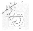
図9は、第3の実施形態に関しており、サポートプレート62のフロントエッジ66をフロントウォール16に当て付けるための手段82が省略されている点で、図1から図7に示す実施形態と異なっている。
FIG. 9 relates to the third embodiment and differs from the embodiments shown in FIGS. 1 to 7 in that the
当付け手段82が省略されているにもかかわらず、ブランケットユニット3の固定および引張りは、満足すべきものであることが分かっている。
Despite the omission of the application means 82, the fixing and pulling of the
上で説明した各実施形態の場合、シリンダおよびブランケットユニットは、互いに個別に販売することができることに留意されたい。 Note that for each of the embodiments described above, the cylinder and blanket unit can be sold separately from each other.
一般的には、上で説明した原理は、2つのブランケットユニット3が、シリンダ2の軸線Aに沿って並べて固定されるシリンダ2と共に使用することができる。
In general, the principle described above can be used with a
各ブランケットユニット3と結合した固定装置42は、軸線Aに対して、互いに、たとえば180°の角度だけオフセットさせることができる。この方法の場合、各ブランケットユニット3と結合した開口14が直径方向に対向することによって、回転中における印刷機の他のシリンダに対する振動を制限し、シリンダ2の全長さを超えて延びることはない。
The fixing
1 オフセット印刷機のためのアセンブリ
2 シリンダ
3 ブランケットユニット
4 シリンダの周囲表面
5 シリンダの長手方向端部
8 長手方向凹所
10 インサート
12 長手方向空胴
14 開口(長手方向開口)
16 フロントウォール
18、22 面取り部分
20 リアウォール
26 固定装置
28 スピンドル(固定装置)
30 フック
32 圧搾エレメント
34 フックの自由端
36 圧搾エレメントの自由端
38 共通のねじ
42 駆動機構(固定装置)
44 サポート
46 ロッド
48 カラー
50 スプリング
52 ブロック
54 スピンドルの長手方向端部
56 移動可能動作レバー
58 調整可能ストップ
62 ブランケットサポートプレート
64 ブランケット
66 ブランケットサポートプレートのフロントエッジ
68 ブランケットのフロントエッジ
70 フロントベンド
72 ブランケットサポートプレートのリアエッジ
74 ブランケットのリアエッジ
76 リアベンド
78 リアエッジの自由端
80 リアエッジの開口
82 当付け手段
84 中間ベンド
86 リアエッジの端部領域
88 リアエッジの中間領域
DESCRIPTION OF
16
44
Claims (16)
ブランケット(64)およびブランケットサポートプレート(62)を備えたブランケットユニット(3)であって、ブランケットサポートプレート(62)のフロントエッジ(66)およびリアエッジ(72)が、それぞれフロントベンド(70)の領域およびリアベンド(76)の領域で曲がり、ブランケットサポートプレート(62)のリアエッジ(72)が、ブランケットの、リアベンド(76)に隣接して位置付けされたリアエッジ(74)を越えて突出したブランケットユニット(3)と、
ブランケットサポートプレート(62)のフロントエッジおよびリアエッジを受け入れるための開口(14)を有するシリンダ(2)であって、ブランケットユニットを引っ張るための、ブランケットサポートプレート(62)のリアエッジ(72)の開口(80)中への受入れるように構成された少なくとも1つのフック(30)を備えた、ブランケットユニット(3)をシリンダに固定するための装置(28)を備え、ブランケットサポートプレート(62)のリアエッジ(72)に実質的に平行な引張り荷重をブランケットサポートプレート(62)に印加するべく開口中にリアエッジ(72)が挿入されるシリンダ(2)と、を備えたタイプのオフセット印刷機のためのアセンブリ(1)において、
ブランケットサポートプレート(62)のフロントエッジ(66)が、ブランケットの、フロントベンド(70)に隣接して位置付けされたフロントエッジ(68)を越えて突出していることを特徴とするアセンブリ。 An assembly (1) for an offset printing press, comprising:
A blanket unit (3) comprising a blanket (64) and a blanket support plate (62), wherein the front edge (66) and the rear edge (72) of the blanket support plate (62) are each in the region of the front bend (70). And the rear edge (72) of the blanket support plate (62) is bent in the area of the rear bend (76) so that the blanket unit (3) protrudes beyond the rear edge (74) of the blanket positioned adjacent the rear bend (76). )When,
A cylinder (2) having an opening (14) for receiving a front edge and a rear edge of a blanket support plate (62), the opening (14) in the rear edge (72) of the blanket support plate (62) for pulling a blanket unit. 80) a device (28) for securing the blanket unit (3) to the cylinder, comprising at least one hook (30) adapted to be received in the rear edge (32) of the blanket support plate (62). A cylinder (2) into which a rear edge (72) is inserted into the opening to apply a tensile load substantially parallel to 72) to the blanket support plate (62). In (1),
An assembly characterized in that the front edge (66) of the blanket support plate (62) projects beyond the front edge (68) of the blanket located adjacent to the front bend (70).
An offset printing press comprising the assembly according to any one of the preceding claims.
Applications Claiming Priority (2)
| Application Number | Priority Date | Filing Date | Title |
|---|---|---|---|
| FR0211620A FR2844743B1 (en) | 2002-09-19 | 2002-09-19 | ASSEMBLY COMPRISING A BLANKET UNIT AND A CYLINDER WITH BLANKET FASTENING DEVICE, CYLINDER, BLANKET UNIT AND OFFSET PRESS THEREOF |
| FR0211620 | 2002-09-19 |
Publications (2)
| Publication Number | Publication Date |
|---|---|
| JP2004268564A true JP2004268564A (en) | 2004-09-30 |
| JP4703109B2 JP4703109B2 (en) | 2011-06-15 |
Family
ID=31897502
Family Applications (1)
| Application Number | Title | Priority Date | Filing Date |
|---|---|---|---|
| JP2003326896A Expired - Fee Related JP4703109B2 (en) | 2002-09-19 | 2003-09-18 | Assembly with blanket unit and cylinder with blanket fixing device, corresponding cylinder, blanket unit and offset printing machine |
Country Status (6)
| Country | Link |
|---|---|
| US (1) | US6901857B2 (en) |
| EP (1) | EP1400356B1 (en) |
| JP (1) | JP4703109B2 (en) |
| CN (1) | CN1307052C (en) |
| DE (1) | DE60306057T2 (en) |
| FR (1) | FR2844743B1 (en) |
Cited By (1)
| Publication number | Priority date | Publication date | Assignee | Title |
|---|---|---|---|---|
| JP2010012747A (en) * | 2008-07-07 | 2010-01-21 | Seiken Graphics Kk | Blanket fixing device of rotary printing machine |
Families Citing this family (5)
| Publication number | Priority date | Publication date | Assignee | Title |
|---|---|---|---|---|
| DE10250684B3 (en) * | 2002-10-31 | 2004-04-01 | Koenig & Bauer Ag | Production of a rotational body of a printing machine comprises forming profiled bodies by welding material to opposite-lying walls of a groove in the peripheral direction of the balls in the machine |
| BRPI0916084A2 (en) * | 2008-11-03 | 2015-11-10 | Trelleborg Engineered Systems Italy S P A | "method for producing a liner for a typographic cylinder, and liner for a typographic cylinder" |
| WO2013042104A1 (en) * | 2011-09-25 | 2013-03-28 | Hewlett Packard Indigo B.V. | Blanket tensioning device |
| NL2020109B1 (en) * | 2017-12-18 | 2019-06-25 | Xeikon Prepress Nv | Method for fixing and treating a flexible plate on a drum, and flexible plate for use therein |
| DE102019111510A1 (en) * | 2019-05-03 | 2020-11-05 | Koenig & Bauer Ag | Printing unit for an offset printing machine with a rubber cylinder carrying at least one rubber blanket and a method for handling a rubber blanket |
Citations (4)
| Publication number | Priority date | Publication date | Assignee | Title |
|---|---|---|---|---|
| JPH08267715A (en) * | 1995-03-16 | 1996-10-15 | Koenig & Bauer Albert Ag | Tensioning device |
| JPH0999543A (en) * | 1995-05-05 | 1997-04-15 | Koenig & Bauer Albert Ag | Device for fixing the rubber blanket unit to the blanket cylinder |
| WO2000073075A2 (en) * | 1999-05-29 | 2000-12-07 | Koenig & Bauer Aktiengesellschaft | Device for fixing a flexible plate |
| JP2002019079A (en) * | 2000-07-12 | 2002-01-22 | Tokyo Kikai Seisakusho Ltd | Blanket cylinder |
Family Cites Families (8)
| Publication number | Priority date | Publication date | Assignee | Title |
|---|---|---|---|---|
| DE8433674U1 (en) * | 1984-11-16 | 1985-02-14 | Maschinenfabrik Wifag, Bern | DEVICE FOR MOUNTING A RUBBER BLANKET ON A RUBBER BLANKET CYLINDER OF A ROTARY PRINTING MACHINE |
| DE4415683C2 (en) * | 1994-05-04 | 1998-04-09 | Roland Man Druckmasch | Device for attaching a flexible pressure plate |
| DE19509563C2 (en) * | 1995-03-16 | 1997-01-23 | Koenig & Bauer Albert Ag | Cylinder with a device for clamping plates |
| DE29600845U1 (en) | 1996-01-19 | 1996-03-07 | MAN Roland Druckmaschinen AG, 63075 Offenbach | Device for fastening a covering on a printing unit cylinder |
| DE19642141C1 (en) * | 1996-10-12 | 1998-06-18 | Koenig & Bauer Albert Ag | Device for releasing plates |
| JP3461487B2 (en) * | 2000-07-06 | 2003-10-27 | 株式会社東京機械製作所 | Printing cylinder mounting device, printing plate and blanket |
| DE10060171C1 (en) * | 2000-12-04 | 2002-05-23 | Koenig & Bauer Ag | Sleeve retainer for printing cylinder has sprung detent to engage ridge formed on flange at end of the sleeve panel |
| DE10060984B4 (en) * | 2000-12-08 | 2006-10-26 | Man Roland Druckmaschinen Ag | Vorichtung for attaching a clothing on a printing cylinder |
-
2002
- 2002-09-19 FR FR0211620A patent/FR2844743B1/en not_active Expired - Fee Related
-
2003
- 2003-09-05 EP EP03292193A patent/EP1400356B1/en not_active Expired - Lifetime
- 2003-09-05 DE DE60306057T patent/DE60306057T2/en not_active Expired - Lifetime
- 2003-09-18 CN CNB031585418A patent/CN1307052C/en not_active Expired - Fee Related
- 2003-09-18 US US10/666,210 patent/US6901857B2/en not_active Expired - Lifetime
- 2003-09-18 JP JP2003326896A patent/JP4703109B2/en not_active Expired - Fee Related
Patent Citations (5)
| Publication number | Priority date | Publication date | Assignee | Title |
|---|---|---|---|---|
| JPH08267715A (en) * | 1995-03-16 | 1996-10-15 | Koenig & Bauer Albert Ag | Tensioning device |
| JPH0999543A (en) * | 1995-05-05 | 1997-04-15 | Koenig & Bauer Albert Ag | Device for fixing the rubber blanket unit to the blanket cylinder |
| WO2000073075A2 (en) * | 1999-05-29 | 2000-12-07 | Koenig & Bauer Aktiengesellschaft | Device for fixing a flexible plate |
| JP2003522045A (en) * | 1999-05-29 | 2003-07-22 | ケーニツヒ ウント バウエル アクチエンゲゼルシヤフト | Equipment for fixing flexible boards |
| JP2002019079A (en) * | 2000-07-12 | 2002-01-22 | Tokyo Kikai Seisakusho Ltd | Blanket cylinder |
Cited By (1)
| Publication number | Priority date | Publication date | Assignee | Title |
|---|---|---|---|---|
| JP2010012747A (en) * | 2008-07-07 | 2010-01-21 | Seiken Graphics Kk | Blanket fixing device of rotary printing machine |
Also Published As
| Publication number | Publication date |
|---|---|
| US20040216629A1 (en) | 2004-11-04 |
| FR2844743A1 (en) | 2004-03-26 |
| CN1495018A (en) | 2004-05-12 |
| US6901857B2 (en) | 2005-06-07 |
| EP1400356A3 (en) | 2004-04-28 |
| HK1064069A1 (en) | 2005-01-21 |
| EP1400356B1 (en) | 2006-06-14 |
| CN1307052C (en) | 2007-03-28 |
| JP4703109B2 (en) | 2011-06-15 |
| DE60306057T2 (en) | 2007-01-04 |
| EP1400356A2 (en) | 2004-03-24 |
| FR2844743B1 (en) | 2004-12-17 |
| DE60306057D1 (en) | 2006-07-27 |
Similar Documents
| Publication | Publication Date | Title |
|---|---|---|
| KR101444467B1 (en) | Thermal printer | |
| JP2584197B2 (en) | Flexible printing plate fixing device | |
| JP2004268564A (en) | Assembly equipped with blanket unit and cylinder having blanket unit fixing device, and corresponding cylinder, blanket unit and offset printing machine | |
| WO1991018147A1 (en) | Doctor blade supporting structure | |
| JP2927782B1 (en) | Paper wrinkle prevention device | |
| JP3090253B2 (en) | Apparatus for slit-shaped holding device | |
| EP1378356B1 (en) | Apparatus for cleaning a cylinder | |
| JP2009023313A (en) | Printing plate mounting apparatus | |
| JPH08252808A (en) | Wood bending method and device | |
| US7503235B2 (en) | Pedal assembly | |
| US7350462B2 (en) | Gap filling member for blanket cylinder | |
| GB2300598A (en) | A blanket cylinder with a device for fastening a rubber-blanket unit | |
| JPS6034858A (en) | Device for holding printing plate to cylinder for printer | |
| US4702166A (en) | Plate lock-up mechanism for printing presses | |
| JPH08238750A (en) | Plate exchanger | |
| JP2513942Y2 (en) | Double band brake device for rotating body | |
| GB2167011A (en) | Rubber blanket cylinder for a rotary printing press | |
| JPH02193B2 (en) | ||
| US6101943A (en) | Cylinder cleaning device and cleaning method | |
| KR101574288B1 (en) | Blade holder for printing apparatus | |
| KR100230467B1 (en) | Fixing and pulling device for cylinder packing in printing machine | |
| JP5148379B2 (en) | Blanket bending machine | |
| JP4907323B2 (en) | Base paper locking device for stencil printing machine | |
| JPH0750155Y2 (en) | Sheet material cutting device with guide | |
| JP2009262225A (en) | Wiper |
Legal Events
| Date | Code | Title | Description |
|---|---|---|---|
| A621 | Written request for application examination |
Free format text: JAPANESE INTERMEDIATE CODE: A621 Effective date: 20060816 |
|
| A977 | Report on retrieval |
Free format text: JAPANESE INTERMEDIATE CODE: A971007 Effective date: 20091102 |
|
| A131 | Notification of reasons for refusal |
Free format text: JAPANESE INTERMEDIATE CODE: A131 Effective date: 20091110 |
|
| A601 | Written request for extension of time |
Free format text: JAPANESE INTERMEDIATE CODE: A601 Effective date: 20100210 |
|
| A602 | Written permission of extension of time |
Free format text: JAPANESE INTERMEDIATE CODE: A602 Effective date: 20100216 |
|
| A521 | Request for written amendment filed |
Free format text: JAPANESE INTERMEDIATE CODE: A523 Effective date: 20100510 |
|
| A01 | Written decision to grant a patent or to grant a registration (utility model) |
Free format text: JAPANESE INTERMEDIATE CODE: A01 Effective date: 20110208 |
|
| A61 | First payment of annual fees (during grant procedure) |
Free format text: JAPANESE INTERMEDIATE CODE: A61 Effective date: 20110308 |
|
| FPAY | Renewal fee payment (event date is renewal date of database) |
Free format text: PAYMENT UNTIL: 20140318 Year of fee payment: 3 |
|
| S111 | Request for change of ownership or part of ownership |
Free format text: JAPANESE INTERMEDIATE CODE: R313111 |
|
| R350 | Written notification of registration of transfer |
Free format text: JAPANESE INTERMEDIATE CODE: R350 |
|
| FPAY | Renewal fee payment (event date is renewal date of database) |
Free format text: PAYMENT UNTIL: 20140318 Year of fee payment: 3 |
|
| S533 | Written request for registration of change of name |
Free format text: JAPANESE INTERMEDIATE CODE: R313533 |
|
| FPAY | Renewal fee payment (event date is renewal date of database) |
Free format text: PAYMENT UNTIL: 20140318 Year of fee payment: 3 |
|
| R350 | Written notification of registration of transfer |
Free format text: JAPANESE INTERMEDIATE CODE: R350 |
|
| R250 | Receipt of annual fees |
Free format text: JAPANESE INTERMEDIATE CODE: R250 |
|
| LAPS | Cancellation because of no payment of annual fees |