JP2004262284A - Electric cable extra length absorber for slide door - Google Patents
Electric cable extra length absorber for slide door Download PDFInfo
- Publication number
- JP2004262284A JP2004262284A JP2003052895A JP2003052895A JP2004262284A JP 2004262284 A JP2004262284 A JP 2004262284A JP 2003052895 A JP2003052895 A JP 2003052895A JP 2003052895 A JP2003052895 A JP 2003052895A JP 2004262284 A JP2004262284 A JP 2004262284A
- Authority
- JP
- Japan
- Prior art keywords
- case
- flat cables
- flat cable
- shape
- flat
- Prior art date
- Legal status (The legal status is an assumption and is not a legal conclusion. Google has not performed a legal analysis and makes no representation as to the accuracy of the status listed.)
- Pending
Links
Images


Abstract
Description
【0001】
【発明の属する技術分野】
本発明は、例えば車輌のスライドドア側と車体側の端子間に配置した電線の余長吸収機構のケース内に、複数本の金属箔導線を絶縁シートにより被覆したフレキシブルフラットケーブル(以下フラットケーブルと云う)を配索して余長を吸収するスライドドアの電線余長吸収装置に関するものである。
【0002】
【従来の技術】
スライドドア内のガラス窓開閉モータ等に給電するために、例えば特開平11−255041号、特開平11−348683号に開示されたスライドドアの給電装置においては、一部の電線余長吸収機構にその屈曲性、弾発性を利用してフラットケーブルが用いられている。
【0003】
そして、これらの余長吸収機構ではフラットケーブルをU字状に屈曲させ、その引込み量を可変にして、スライドドアの開閉に伴う余長を吸収している。
【0004】
【発明が解決しようとする課題】
しかし、これらの余長吸収機構におけるフラットケーブルは、片側にのみU字状に屈曲しているために、フラットケーブルが右行と左行では操作力が異なり、接続個所における断線の虞れなどがある。また、回路数によってフラットケーブルを多数枚積層しなければならない場合があり、フラットケーブル同士の摩擦等により抵抗力が大きくなり、操作に力を要する問題点もある。
【0005】
本発明の目的は、上述した問題点を解消し、ケース内のフラットケーブルを左右対称にU字状に弯曲してループ状に配索することにより、フラットケーブルに加わる応力を平衡させ、フラットケーブル同士の摩擦を低減して、操作力の低減を図るスライドドアの電線余長吸収装置を提供することにある。
【0006】
【課題を解決するための手段】
上記目的を達成するための本発明に係るスライドドアの電線余長吸収装置は、スライドドア側と本体側との間を配線する配線構造の途中に設けた電線余長吸収装置において、細長のケースと、該ケースの片面に設けた固定部と、他面に設けた摺動部と、前記固定部と摺動部間を前記ケース内において結ぶ少なくとも2枚のフラットケーブルとを備え、前記フラットケーブルを両側に分けてそれぞれU字状に弯曲してループ状に配索したことを特徴とする。
【0007】
【発明の実施の形態】
本発明を図示の実施の形態に基づいて詳細に説明する。
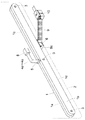
図1は概略斜視図、図2はケースの一部を取り外した状態の斜視図を示し、1は金属又は合成樹脂から成り、フラットケーブルの余長を吸収する機構を内蔵したケースであり、スライドドア2の下辺の開閉方向に沿って固定されている。
【0008】
このケース1は断面矩形状の細長形状とされ、断面「コ」字状の2つ割りの部材1a、1bが、長手方向に沿った3個所においてボルト3により筐体状に組み立てられている。ケース1の上面1cには、フラットケーブル4をケース1内に導入する箱形の固定部材5が固定されており、ケース1の下面1dには箱形の摺動部材6が長手方向に形成されたスリット7に沿って摺動できるように取り付けられている。
【0009】
固定部材5を介してケース1に導入されるフラットケーブル4は、ケース1の外部においては例えば5枚の長尺のフラットケーブル4a〜4eが重ね合わされ、スライドドア2側に設けられた図示しないコネクタに嵌合するドア側コネクタ8に接続されている。
【0010】
これらのフラットケーブル4a〜4eは、固定部材5内において折曲によって方向変換されてケース1内に導入され、フラットケーブル4a〜4cとフラットケーブル4d、4eは図2に示すように、ケース1内においてそれぞれ反対方向に対称的に分けられ、それぞれU字状に弯曲されて全体としてループ形状に配索されている。
【0011】
これらのフラットケーブル4a〜4eは、このループ部を介して下面1dの摺動部材6において再び集合して重ね合わされ、折曲による方向変換によって、重ね合わされたまま摺動部材6から外部に導出され、蛇腹状の可撓性を有する保護管9を通って、渡り部として車体の下部に配置された車体側コネクタ10に接続されている。なお、保護管9内において、必要に応じてフラットケーブル4a〜4eに金属ばね板材を沿わせることもできる。
【0012】
フラットケーブル4a〜4eは固定部材5、摺動部材6内において折曲されると共に、固定部材5、摺動部材6内に設けられた図示しないピンを、フラットケーブル4a〜4eの絶縁シートに挿通することにより、固定部材5、摺動部材6に折曲状態で固定されている。
【0013】
ケース1内において、フラットケーブル4a〜4eは左右にループ状に展開することになるが、摺動部材6の左右の摺動に対応してケース1内で追従できるように、その両側には空間的な余裕が設けられている。ケース1内でのフラットケーブル4a〜4eのU字状の屈曲は、弾性限界を超えないような大き目の曲率半径が選択されている。
【0014】
更に、ケース1内のフラットケーブル4a〜4eの外側には、図3に示すように金属ばね板材11が沿わされており、フラットケーブル4a〜4eを保護すると共に、フラットケーブル4a〜4eに弾性力を与えている。そして、フラットケーブル4a〜4eは金属ばね板材11を含めて、外側のフラットケーブルほどその長さを大きくして、内側のフラットケーブルと摩擦等の干渉が少なくなるようにしている。
【0015】
なお、ケース1内の金属ばね板材11は、フラットケーブル4a〜4eがケース1の内面に摺動して損傷や絶縁不良を生ずることを防止する役割を果たしているが、フラットケーブル4a〜4eが可動しても損傷等の虞れがなく、かつ十分な弾性力を有していれば、この金属ばね板材11を省略することもできる。
【0016】
摺動部材6には、図4に示すように上下の中間部に幅細部6aが設けられており、この幅細部6aがケース1の下面1dに沿ったスリット7に嵌合して摺動できるようにされている。ケース1の内部に位置する上部摺動部6bにおいて、図5に示すようにフラットケーブル4a〜4eは面を上下に向けていたループ形状のAの状態から、面を摺動方向と平行な前後方向に向けて折曲されたBの状態で、幅細部6a内を立ち下がって下部摺動部6cに至り、下部摺動部6c内において面を摺動方向に直交する左右方向に向けると共に、全体を水平方向に向けて折曲したCの状態で摺動部材6の出口6dから導出されている。
【0017】
スライドドア2が開閉するとケース1も共に動くことになるが、車体側コネクタ10は不動であるので、保護管9を介して摺動部材6がケース1のスリット7に沿って図2のほぼ実線から点線の範囲まで、相対的に摺動することになる。このとき、ケース1内のフラットケーブル4a〜4eはループ形状を維持しながら、ケース1内を点線で示すように移動して車体側コネクタ10に対する余長を調整することができる。
【0018】
この場合に、保護管9に保護された渡り部のフラットケーブル4a〜4eの長さを稍々長くして弾性的に弯曲できるようにしておけば、摺動部材6と車体側コネクタ10間にゆとりを持たせることができ、この部分におけるフラットケーブル4a〜4eに過度の緊張を与えることがない。なお、保護管9内のフラットケーブル4a〜4eに前述したように金属ばね板材を沿わせることにより、摺動部材6から外部への出口6dにおいて、摺動部材6が移動してもフラットケーブル4a〜4eは過度に屈曲することがなく、耐久性が向上する。
【0019】
このように実施の形態においては、複数枚のフラットケーブルをコネクタ8からコネクタ10まで切れ目なく使用したが、フラットケーブルはケース1内でのみ使用し、ケース1の外部においては通常の電線を使用することもできる。また、フラットケーブルの重ね合わせ枚数には特に限定はないが、ケース1内における左右のU字部においてほぼ同数であることが、応力を平衡させる意味で好ましい。
【0020】
また、フラットケーブルの繰り返しての屈曲は所定の曲率半径以下にならない限り、十分な耐久性があることは、既に各種の電気機器において実証されている。
【0021】
また、スライドドア、車体の形状、或いはスライドドアの動きに合わせて、ケース1の下面に例えば図6に示すような傾斜部1eを設けて、摺動部材6をこの傾斜部1eに沿って摺動させることもできる。
【0022】
なお実施の形態においては、本発明を自動車に適用した場合を説明したが、車輌に限定されず、建造物などのスライドドアに対しても利用が可能である。
【0023】
【発明の効果】
以上説明したように本発明に係るスライドドアの電線余長吸収装置は、ケース内においてフラットケーブルを左右に対称的に分けてループ状としているため、フラットケーブル同士の摩擦力が少なくなり、応力も平衡するので操作力が少なくて済む。
【図面の簡単な説明】
【図1】実施の形態の斜視図である。
【図2】ケースの一部を取り外した状態の斜視図である。
【図3】ケース内のフラットケーブルの説明図である。
【図4】摺動部材の斜視図である。
【図5】摺動部材内におけるフラットケーブルの折曲状態の説明図である。
【図6】他の実施の形態のケースの正面図である。
【符号の説明】
1 ケース
2 スライドドア
4a〜4e フラットケーブル
5 固定部材
6 摺動部材
7 スリット
8 ドア側コネクタ
9 保護管
10 車体側コネクタ
11 金属ばね板材[0001]
TECHNICAL FIELD OF THE INVENTION
The present invention provides, for example, a flexible flat cable (hereinafter referred to as a flat cable) in which a plurality of metal foil conductors are covered with an insulating sheet in a case of an extra length absorbing mechanism of an electric wire arranged between a sliding door side of a vehicle and a terminal on a vehicle body side. The present invention relates to an apparatus for absorbing an excess wire length of a slide door for arranging the excess length by arranging the excess wire length.
[0002]
[Prior art]
In order to supply power to a glass window opening / closing motor or the like in a slide door, for example, in a power supply apparatus for a slide door disclosed in JP-A-11-255041 and JP-A-11-348683, a part of the wire extra length absorption mechanism is provided. Flat cables are used by utilizing their flexibility and elasticity.
[0003]
In these extra length absorbing mechanisms, the flat cable is bent in a U-shape, and the amount of retraction is made variable to absorb the extra length associated with opening and closing the slide door.
[0004]
[Problems to be solved by the invention]
However, since the flat cables in these extra length absorbing mechanisms are bent in a U-shape only on one side, the operating force is different between the right and left rows of the flat cable, and there is a possibility of disconnection at the connection point. is there. Further, depending on the number of circuits, a large number of flat cables may need to be stacked, and the resistance may increase due to friction between the flat cables and the like, and there is also a problem that operation requires power.
[0005]
SUMMARY OF THE INVENTION An object of the present invention is to solve the above-mentioned problems and to balance a stress applied to a flat cable by bending a flat cable in a case into a U-shape in a symmetrical manner and arranging the flat cable in a loop. An object of the present invention is to provide an apparatus for absorbing an excess wire length of a sliding door, which reduces friction between the sliding doors and reduces operating force.
[0006]
[Means for Solving the Problems]
In order to achieve the above object, an apparatus for absorbing excess wire length of a slide door according to the present invention is a device for absorbing excess wire length provided in the middle of a wiring structure for wiring between a slide door side and a main body side. And a fixed portion provided on one surface of the case, a sliding portion provided on the other surface, and at least two flat cables connecting the fixed portion and the sliding portion in the case. Are divided into two sides, each of which is bent in a U-shape and arranged in a loop.
[0007]
BEST MODE FOR CARRYING OUT THE INVENTION
The present invention will be described in detail based on the illustrated embodiment.
FIG. 1 is a schematic perspective view, and FIG. 2 is a perspective view with a part of the case removed. Reference numeral 1 denotes a case made of metal or synthetic resin and having a built-in mechanism for absorbing an extra length of a flat cable. The
[0008]
The case 1 has an elongated shape having a rectangular cross section, and two
[0009]
The flat cable 4 introduced into the case 1 via the
[0010]
The
[0011]
These
[0012]
The
[0013]
In the case 1, the
[0014]
Further, a
[0015]
The metal
[0016]
As shown in FIG. 4, the sliding
[0017]
When the sliding
[0018]
In this case, if the length of the
[0019]
As described above, in the embodiment, a plurality of flat cables are used seamlessly from the
[0020]
It has already been demonstrated in various electric devices that the flat cable has sufficient durability as long as the repeated bending of the flat cable does not fall below a predetermined radius of curvature.
[0021]
Further, an
[0022]
In the embodiment, the case where the present invention is applied to an automobile has been described. However, the present invention is not limited to a vehicle and can be used for a sliding door of a building or the like.
[0023]
【The invention's effect】
As described above, the wire slack absorbing device for a slide door according to the present invention, since the flat cables are symmetrically divided into left and right loops in the case, the frictional force between the flat cables is reduced, and the stress is also reduced. Equilibrium reduces operating force.
[Brief description of the drawings]
FIG. 1 is a perspective view of an embodiment.
FIG. 2 is a perspective view showing a state where a part of a case is removed.
FIG. 3 is an explanatory diagram of a flat cable in a case.
FIG. 4 is a perspective view of a sliding member.
FIG. 5 is an explanatory diagram of a bent state of a flat cable in a sliding member.
FIG. 6 is a front view of a case according to another embodiment.
[Explanation of symbols]
DESCRIPTION OF SYMBOLS 1
Claims (4)
Priority Applications (1)
| Application Number | Priority Date | Filing Date | Title |
|---|---|---|---|
| JP2003052895A JP2004262284A (en) | 2003-02-28 | 2003-02-28 | Electric cable extra length absorber for slide door |
Applications Claiming Priority (1)
| Application Number | Priority Date | Filing Date | Title |
|---|---|---|---|
| JP2003052895A JP2004262284A (en) | 2003-02-28 | 2003-02-28 | Electric cable extra length absorber for slide door |
Publications (1)
| Publication Number | Publication Date |
|---|---|
| JP2004262284A true JP2004262284A (en) | 2004-09-24 |
Family
ID=33117650
Family Applications (1)
| Application Number | Title | Priority Date | Filing Date |
|---|---|---|---|
| JP2003052895A Pending JP2004262284A (en) | 2003-02-28 | 2003-02-28 | Electric cable extra length absorber for slide door |
Country Status (1)
| Country | Link |
|---|---|
| JP (1) | JP2004262284A (en) |
Cited By (2)
| Publication number | Priority date | Publication date | Assignee | Title |
|---|---|---|---|---|
| JP2006306267A (en) * | 2005-04-28 | 2006-11-09 | Furukawa Electric Co Ltd:The | Slide door power supply device |
| WO2009096324A1 (en) * | 2008-01-29 | 2009-08-06 | Autonetworks Technologies, Ltd. | Wire harness for automobile |
Citations (5)
| Publication number | Priority date | Publication date | Assignee | Title |
|---|---|---|---|---|
| JPH08304625A (en) * | 1995-04-28 | 1996-11-22 | Kyocera Corp | Polarizing element and its production |
| JPH08340625A (en) * | 1995-02-02 | 1996-12-24 | Gleason Reel Corp | System of driving power supply chain and chain carriage |
| JPH11342807A (en) * | 1998-06-03 | 1999-12-14 | Yazaki Corp | Method of preventing flexible flat cable from sagging in feeding device for automobile slide door and sagging preventive structure therefor |
| JP2000050472A (en) * | 1998-07-28 | 2000-02-18 | Yazaki Corp | Protective structure of flexible flat cable |
| JP2000092679A (en) * | 1998-09-09 | 2000-03-31 | Toyota Auto Body Co Ltd | Cable wiring structure between fixed member and movable member |
-
2003
- 2003-02-28 JP JP2003052895A patent/JP2004262284A/en active Pending
Patent Citations (5)
| Publication number | Priority date | Publication date | Assignee | Title |
|---|---|---|---|---|
| JPH08340625A (en) * | 1995-02-02 | 1996-12-24 | Gleason Reel Corp | System of driving power supply chain and chain carriage |
| JPH08304625A (en) * | 1995-04-28 | 1996-11-22 | Kyocera Corp | Polarizing element and its production |
| JPH11342807A (en) * | 1998-06-03 | 1999-12-14 | Yazaki Corp | Method of preventing flexible flat cable from sagging in feeding device for automobile slide door and sagging preventive structure therefor |
| JP2000050472A (en) * | 1998-07-28 | 2000-02-18 | Yazaki Corp | Protective structure of flexible flat cable |
| JP2000092679A (en) * | 1998-09-09 | 2000-03-31 | Toyota Auto Body Co Ltd | Cable wiring structure between fixed member and movable member |
Cited By (4)
| Publication number | Priority date | Publication date | Assignee | Title |
|---|---|---|---|---|
| JP2006306267A (en) * | 2005-04-28 | 2006-11-09 | Furukawa Electric Co Ltd:The | Slide door power supply device |
| WO2009096324A1 (en) * | 2008-01-29 | 2009-08-06 | Autonetworks Technologies, Ltd. | Wire harness for automobile |
| JP2009179117A (en) * | 2008-01-29 | 2009-08-13 | Autonetworks Technologies Ltd | Wire harness for automobile |
| US20100263926A1 (en) * | 2008-01-29 | 2010-10-21 | Autonetworks Technologies, Ltd. | Wire harness for automobile |
Similar Documents
| Publication | Publication Date | Title |
|---|---|---|
| US7042738B2 (en) | Power-supply wiring device and harness layout structure by the power-supply wiring device | |
| CN101150938B (en) | Electronic apparatus | |
| JP3435688B2 (en) | Flexible flat cable protection structure | |
| US8816525B2 (en) | Electric power supply device for sliding door | |
| US20180178740A1 (en) | Wiring structure for sliding door | |
| US20100263926A1 (en) | Wire harness for automobile | |
| US20120132465A1 (en) | Wire harness arrangement structure | |
| JP2004187375A (en) | Feeder arrangement and harness cabling structure using the same | |
| WO2016114183A1 (en) | Electrical wire protective member, electrical wire protective member-equipped wire harness, and slide wiring device | |
| KR20160072173A (en) | Wire harness routing structure | |
| WO2016170946A1 (en) | Covering material for wire harness and wire harness routing structure | |
| WO2018180395A1 (en) | Covering and wire harness | |
| JP6947564B2 (en) | Wire harness wiring structure | |
| JP4220325B2 (en) | Wire surplus length absorber | |
| JP2004262284A (en) | Electric cable extra length absorber for slide door | |
| JP2004357360A (en) | Feeder system | |
| JP2008149871A (en) | Protection material for flat harness, and flat harness | |
| JP3908992B2 (en) | Power feeding device and harness wiring structure using the same | |
| JP2004319254A (en) | Bending part of flat cable | |
| JP2007076408A (en) | Feeding device using flat cable | |
| JP5264566B2 (en) | Wiring harness wiring structure | |
| JP2004248431A (en) | Feeding structure for slide door | |
| JP4070134B2 (en) | Bending structure of laminated flat cable | |
| JP2004350405A (en) | Feeder system | |
| JP6933616B2 (en) | Wire harness with exterior and its wiring structure |
Legal Events
| Date | Code | Title | Description |
|---|---|---|---|
| A621 | Written request for application examination |
Free format text: JAPANESE INTERMEDIATE CODE: A621 Effective date: 20051208 |
|
| A711 | Notification of change in applicant |
Free format text: JAPANESE INTERMEDIATE CODE: A712 Effective date: 20060317 |
|
| A131 | Notification of reasons for refusal |
Free format text: JAPANESE INTERMEDIATE CODE: A131 Effective date: 20080819 |
|
| A521 | Written amendment |
Free format text: JAPANESE INTERMEDIATE CODE: A523 Effective date: 20081020 |
|
| A02 | Decision of refusal |
Free format text: JAPANESE INTERMEDIATE CODE: A02 Effective date: 20081118 |